XFEL High Power RF System Recent Developments
|
|
|
- Stewart Kelley
- 5 years ago
- Views:
Transcription
1 XFEL High Power RF System Recent Developments for the XFEL RF Group
2 Outline XFEL RF System Requirements Overview Basic Layout RF System Main Components Multibeam Klystrons Modulator RF Waveguide Distribution RF Interlock Preamplifier 2
: 3.")

 600μs 1.")
3 RF System Requirements Number of sc cavities: 928 total Power per cavity: 122 kw Gradient at 20GeV: 23.6 MV/m Power per 32 cavities (4 cryo modules): 3.9MW Power per RF station: 5.2MW (including 10% losses in Number of RF stations: Number of RF stations for injectors: 2 (5) Macro beam pulse duration: RF pulse duration: Repetition rate: Average RF power per station: 29 (26 active) 600μs 1.38ms 10Hz (30Hz) 72kW (150kW) waveguides and circulators and a regulation reserve of 15%) 3
4 RF System Requiremets Overview Layout of the RF Station Accelerator Tunnel Modulator Modulator Hall 4

 will be installed under the cryo module.")

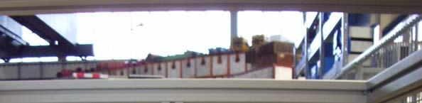
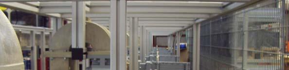
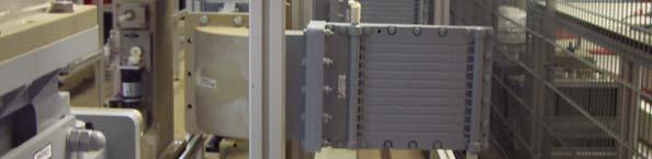
5 RF System Requirements XFEL Layout of the RF Station in the Accelerator Tunnel Tunnel components (klystrons, pulse transformers, aux. power supplies etc.) will be installed under the cryo module. The waveguide distribution will be installed on the side of the cryo module. These components are not accessible during accelerator operation. 5


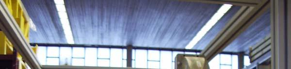
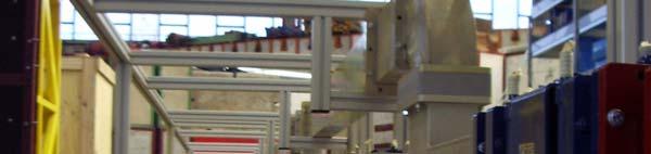
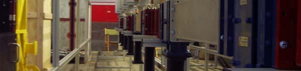
6 RF System Requirements Layout of the RF Station in the Modulator Hall XFEL The modulators will be installed in the modulator hall. 7x5 modulators in one hall. Maintenance and repair is possible during accelerator operation. 6


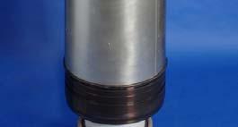
7 Multibeam Klystrons DESY asked 3 klystron vendors to develop MBK THALES TH1801 CPI VKL8301 TOSHIBA E3736 7


8 THALES TH1801 Operation Frequency: 1.3GHz Cathode Voltage: < 120 kv Beam Current: < 140 A Max. RF Peak Power: 10MW RF Pulse Duration: 1.5ms Repetition Rate: 10Hz RF Average Power: 150kW Efficiency: ce cy 65% Solenoid Power: < 5.5kW Length: 2.5m 8
9 Status of the THALES TH1801 prototype: 20, hours operation since May 2000, stored at DESY series tube #003 in operation at FLASH since March 2006 (total operation time: ca: h) #001 was in operation at PITZ in Zeuthen till November 2006, now in operation at the klystron test stand in Hamburg #002 under reconstruction at Thales #004 fully tested at klystron test stand in Hamburg (250 hours), now in operation at PITZ, Zeuthen #005 new tube with modification in test at Thales TH1801-SN5 500µs RF 1300 MHz- 578µs 27 Hz 118kV-142A HV Summary: all tubes which are now in operation do not show signs of degradation (no arcing, no 0 perveance drops) (MW) Ps Pd (W) 9


")
10 Multi Beam Klystron CPI VKL-8301 Design Features: 6 beams HOM input and output cavity Cathode loading: <2.5A/cm 2 lifetime prediction: >100000h Status: Data taken at the klystron test stand at DESY 9 MW at 300 μs and 10Hz 8.1 MW at 1.3 ms and 10Hz 55 ) Efficiency (% Pout (MW) 10


 2 80 85")
11 The TOSHIBA E3736 MBK Design Features: 6 beams Ring shaped cavities Cathode loading: <2.1 A/cm 2 Status: June 8 - October 12, MW, 1500 μs, 10 Hz, kv, h ~ 66% 750h at full power, at present stored at DESY Pout (MW) Toshiba MBK, June 2006 U =115,8kV, I = 134A, Trf = 1500μS Pin (W) W) Output power (M Toshiba MBK (saturation mode) Beam Voltage (kv) 11
12 Status of the vertical MBK development XFEL 6 THALES TH1801 have been built (10MW, 1.5ms, 10Hz, 63% for #3), 1 is in test at THALES klystrons in use at FLASH, PITZ, MBK test stand, several thousends of operation hours under different conditions, now stable operation 1 TOSHIBA E3736 at DESY (10.4MW, 1.5ms, 10Hz, 66%), 750h operation hours 1 CPI VKL8301 at DESY (8.1MW, 1.3ms, 10Hz, 53%) 12
13 Horizontal MBK prototypes Horizontal klystron, side view D Top view Horizontal versions of MBKs by all 3 vendors (THALES, CPI, TOSHIBA) are under construction First klystron is expected in second half of
14 Modulator Modulator Requirements Modulators must generate HV pulses up to 120kV and 140A, 1.57ms pulse length and 10Hz (30Hz) repetition rate The top of the pulse must be flat within 1% The bouncer type modulator with its simple circuit diagram was chosen CHARGING L1 10 kv S1 3 H 1.4 ms 70 kj µf 100 µf 80Ω MOV Klystron U C1 U C2 19% t ΔU tot 1% C2 2 mf + L2 330 µh 1:12 Pulse Transformer 14

")

; 7 IGCTs in series, 2 are redundant Low leakage")

15 Modulator 3 bouncer modulators have been developed, built and delivered to TTF by FNAL since 1994 They are continuosly in operation under different operation conditions Industry made subunits (PPT, ABB, FUG, Poynting) Constant power power supply for suppression of 10Hz repetition rate disturbances in the mains Compact storage capacitor bank with self healing capacitors IGCT Stack (ABB); 7 IGCTs in series, 2 are redundant Low leakage inductance pulse transformer (ABB) L<200μH resulting in shorter HV pulse rise time of <200μs Light Triggered Thyristor crowbar avoiding mercury of ignitrons 15


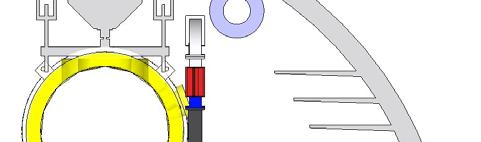
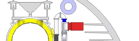
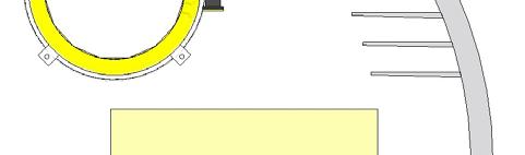
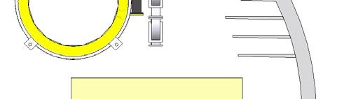
16 Modulator for Pulse Cable Tests Bouncer at high potential Modulator in hall 2 Low leakage inductance circuit 16
 New modified modulator is installed at DESY hall 2 and will")
17 HV Pulse Cable Test Pulse transmission has been successful tested at TTF/FLASH Modulator 5. EMI caused by cable required modification of modulator internal layout (lower leakage inductances, EMC cabinets, bouncer at high potential) New modified modulator is installed at DESY hall 2 and will supply HV pulses via a 1.5km long cable to PT/Klystron in hall 3 (FLASH) during part of the next operation period of FLASH Primary Current 1.1kA 1kA Klystron Voltage 128kV Primary Voltage 10.6kV 17
18 Qualification of additional modulator vendors 2 additional XFEL prototype modulators have been ordered to qualify additional vendors besides the already know vendors of bouncer modulator components like PPT, ABB, FUG, Poynting One modulator is a bouncer modulator by Imtech/Vonk NL The other modulator is a PSM modulator by Thomson BM CH: Much experience of about 20years exists with PSM modulators for SLS, fusion or radio station applications Test of these devices is planned for 2008 at the modulator test facility at DESY Zeuthen. 18
19 Modulator Planned Modulator Test Facility at DESY in Zeuthen 19
20 Bouncer Modulator Test Installation at DESY Zeuthen is foreseen for spring
21 PSM Modulator PSM Modulator by Thomson BM Installation at DESY Zeuthen is foreseen for spring
22 Modulator Status Modulator 11 Bouncer Modulators have been built, 3 by FNAL and 8 together with industry 11 modulators are in operation (FLASH, PITZ, XFEL Teststands) 10 years operation experience exists Modulator foreseen for waveguide tests will be installed in DESY hall 2 and connected to PT and klystron in hall 3 (Bouncer type plus improvements) and used for pulse cable tests Order for more XFEL prototypes has been placed (1 Bouncer plus 1 PSM) Test of prototypes in Zeuthen starting spring
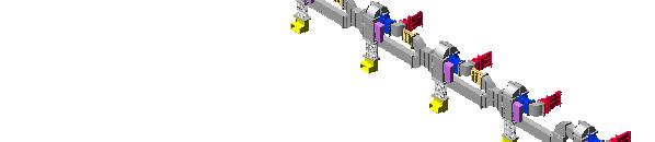
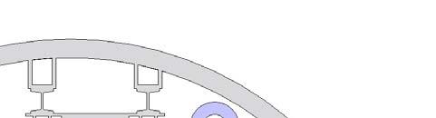
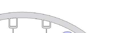
23 Waveguide Distribution Distribution ib i of klystron output power to the superconducting cavities i Protection of the klystron from reflected power Control of phase Cryomodule 1 Cryomodule 2 Cryomodule 3 Cryomodule 4 RF from klystron to cavity DETAIL Phase shifter circulator loads hybrid 23


 RF Load (Ferrite) RF Load (Ferrite) Directivity, db")
 Accuracy of coupling")

 Physical length, mm")

24 Waveguide Distribution Many wave guide components have been developed over the last years and have been used for the operation of TTF/FLASH 3 Stub Tuner (IHEP, Bejing, China) E and H Bends (Spinner) Circulator (Ferrite) Changing phase, degree 60 Impedance matching range 1/3Zw 3Zw Max power, MW 2 * Zw waveguide impedance Hybrid Coupler (RFT, Spinner) Type WFHI 3-4 Peak input power, MW 0.4 Average power, kw 8 Min isolation at 1.3 GHz, db > 30 Max insertion loss at 1.3 GHz, db 0.08 Input SWR at 1.3 GHz 1.1 (for full reflection) RF Load (Ferrite) RF Load (Ferrite) Directivity, db Return loss, db Coupling factor, db (due to tolerance overlapping only 13 different coupling factors instead 18 are nessesary) Accuracy of coupling factor, db ; 12.0; 11.4; 10.7; 10.1; 9.6; 9.1; 8.5; 7.8; 7.0; 6.0; 4.8; Type WFHLL 3-1 Peak input power, MW 1.0 Average power, kw 0.2 Min return loss at 1.3GHz, db Max VSWR at 1.3 GHz 1.05 Max surface temperature, T C 50 (for full average power) Physical length, mm 230 Type WFHL 3-1 WFHL 3-5 Peak input power, M W Average power, kw Min return loss at 1.3 GHz, db Max VSWR at 1.3 GHz <1.05 <1.05 Max surface temperature, Δ T C (for full average power) Physical length, mm
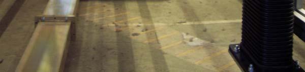
25 Waveguide Distribution A New Waveguide Distribution for the XFEL has been developed. It will be tested with ACC6 at TTF/FLASH Standard d FLASH like Distribution ib ti Combined System with shunt tees: less space, less parts, less weight, lower costs, must be tested, planned for ACC6 at FLASH 25

26 Old and new waveguide distribution XFEL OLD NEW 26

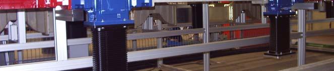
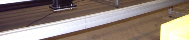
27 Waveguide distribution in Halle II XFEL FLASH like Combined system 27
28 Waveguide distribution with shunt tees Shunt tee with integrated phaseshifters Asymmetric shunt tee 3.0 db, 4.77 db, 6.0 db Fixed phaseshifters 28


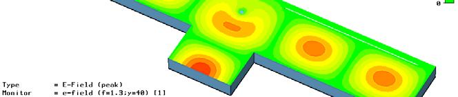
29 New Binary Cell with shunt tee with integrated phase shifter 29


30 Asymmetric shunt tee Coupling ratio 6dB post 1 post 2 70 Post position 60 z1 1, x2, mm S21 30
31 Phasing of wavegude distribution XFEL Combined system with asymmetric shunt tees -212º -212º -212º 165,1 12,0 212º 0º 212º 0º 212º 0º 0º Linear system with hybrids - FLASH like 115º -40º -25º -15º a= 165,1 mm -115º 0º 40º 25º 0º 15º 0º 10º 5º -5º 31
32 RF Interlock Zeuthen/HH development FPGA Based Version #2 installed at FLASH Version #3 installed at PITZ and module test facility, will be tested at FLASH too Version #3 allows setting of interlocks remote controlled 32
33 Preamplifier Specification reworked Several new amplifiers are ordered, some received and in test Will be used at MBK teststand, FLASH, Zeuthen 33
34 HV Pulse Cable Transmission of HV pulses (10kV, 1.6kA, 1.57ms, 10Hz (30Hz)) from the pulse generating unit (modulator hall) to the pulse transformer (accelerator tunnel) Maximum length 1.5km Impedance of 25 Ohms (4 cable in parallel will give 6.25 Ohms in total) to match the klystron impedance Triaxial construction (inner conductor at 10kV, middle conductor at 1kV, outer conductor at ground) diameter 30mm dielectric material: XLPE 34
INFN School on Electron Accelerators. RF Power Sources and Distribution
 INFN School on Electron Accelerators 12-14 September 2007, INFN Sezione di Pisa Lecture 7b RF Power Sources and Distribution Carlo Pagani University of Milano INFN Milano-LASA & GDE The ILC Double Tunnel
The TESLA RF System. S. Choroba. for the TESLA Collaboration. DESY Notkestr. 85, D Hamburg, Germany
 The TESLA RF System S. Choroba for the TESLA Collaboration DESY Notkestr. 85, D-22603 Hamburg, Germany Abstract. The TESLA project proposed by the TESLA collaboration in 2001 is a 500 to 800GeV e+/e- linear
Detailed Design Report
 Detailed Design Report Chapter 4 MAX IV Injector 4.6. Acceleration MAX IV Facility CHAPTER 4.6. ACCELERATION 1(10) 4.6. Acceleration 4.6. Acceleration...2 4.6.1. RF Units... 2 4.6.2. Accelerator Units...
A HIGH POWER LONG PULSE HIGH EFFICIENCY MULTI BEAM KLYSTRON
 A HIGH POWER LONG PULSE HIGH EFFICIENCY MULTI BEAM KLYSTRON A.Beunas and G. Faillon Thales Electron Devices, Vélizy, France S. Choroba DESY, Hamburg, Germany Abstract THALES ELECTRON DEVICES has developed
L-Band RF R&D. SLAC DOE Review June 15 th, Chris Adolphsen SLAC
 L-Band RF R&D SLAC DOE Review June 15 th, 2005 Chris Adolphsen SLAC International Linear Collider (ILC) RF Unit (TESLA TDR Layout) Gradient = 23.4 MV/m Bunch Spacing = 337 ns Fill Time = 420 µs Train Length
Pulses inside the pulse mode of operation at RF Gun
 Pulses inside the pulse mode of operation at RF Gun V. Vogel, V. Ayvazyan, K. Floettmann, D. Lipka, P. Morozov, H. Schlarb, S. Schreiber FLASH Seminar, DESY March 29, 2011 Contents Why we need a PiPmode
DESIGN AND PERFORMANCE OF L-BAND AND S-BAND MULTI BEAM KLYSTRONS
 DESIGN AND PERFORMANCE OF L-BAND AND S-BAND MULTI BEAM KLYSTRONS Y. H. Chin, KEK, Tsukuba, Japan. Abstract Recently, there has been a rising international interest in multi-beam klystrons (MBK) in the
RF plans for ESS. Morten Jensen. ESLS-RF 2013 Berlin
 RF plans for ESS Morten Jensen ESLS-RF 2013 Berlin Overview The European Spallation Source (ESS) will house the most powerful proton linac ever built. The average beam power will be 5 MW which is five
ILC RF System R&D. Chris Adolphsen, SLAC. Section of 1.3 GHz SC Linac. June 29, 2007 PAC07 Talk FRYC01
 ILC RF System R&D Chris Adolphsen, SLAC June 29, 2007 PAC07 Talk FRYC01 Section of 1.3 GHz SC Linac ILC Main Linac RF Unit (1 of 560) RF System Gradient = 31.5 MV/m Rep Rate = 5 Hz Beam Current = 9.0 ma
IOT OPERATIONAL EXPERIENCE ON ALICE AND EMMA AT DARESBURY LABORATORY
 IOT OPERATIONAL EXPERIENCE ON ALICE AND EMMA AT DARESBURY LABORATORY A. Wheelhouse ASTeC, STFC Daresbury Laboratory ESLS XVIII Workshop, ELLETRA 25 th 26 th November 2010 Contents Brief Description ALICE
Pulsed Klystrons for Next Generation Neutron Sources Edward L. Eisen - CPI, Inc. Palo Alto, CA, USA
 Pulsed Klystrons for Next Generation Neutron Sources Edward L. Eisen - CPI, Inc. Palo Alto, CA, USA Abstract The U.S. Department of Energy (DOE) Office of Science has funded the construction of a new accelerator-based
Status of BESSY II and berlinpro. Wolfgang Anders. Helmholtz-Zentrum Berlin for Materials and Energy (HZB) 20th ESLS-RF Meeting
 20th ESLS-RF Meeting") Status of BESSY II and berlinpro Wolfgang Anders Helmholtz-Zentrum Berlin for Materials and Energy (HZB) 20th ESLS-RF Meeting 16.-17.11.2016 at PSI Outline BESSY II Problems with circulators Landau cavity
Status of BESSY II and berlinpro Wolfgang Anders Helmholtz-Zentrum Berlin for Materials and Energy (HZB) 20th ESLS-RF Meeting 16.-17.11.2016 at PSI Outline BESSY II Problems with circulators Landau cavity
WG2 Group Summary. Chris Adolphsen Terry Garvey Hitoshi Hayano
 WG2 Group Summary Chris Adolphsen Terry Garvey Hitoshi Hayano Linac Options Fest On Thursday afternoon, various experts summarized the linac baseline options. Although hard choices have yet to be made,
Introduction: CW SRF linac types, requirements and challenges High power RF system architecture
 RF systems for CW SRF linacs S. Belomestnykh Cornell University Laboratory for Elementary-Particle Physics LINAC08, Victoria, Canada October 1, 2008 Outline L band Introduction: CW SRF linac types, requirements
ILC-LNF TECHNICAL NOTE
 IL-LNF EHNIAL NOE Divisione Acceleratori Frascati, July 4, 2006 Note: IL-LNF-001 RF SYSEM FOR HE IL DAMPING RINGS R. Boni, INFN-LNF, Frascati, Italy G. avallari, ERN, Geneva, Switzerland Introduction For
A New 4MW LHCD System for EAST
 1 EXW/P7-29 A New 4MW LHCD System for EAST Jiafang SHAN 1), Yong YANG 1), Fukun LIU 1), Lianmin ZHAO 1) and LHCD Team 1) 1) Institute of Plasma Physics, Chinese Academy of Sciences, Hefei, China E-mail
TOSHIBA Industrial Magnetron E3328
 TOSHIBA E3328 is a fixed frequency continuous wave magnetron intended for use in the industrial microwave heating applications. The average output power is 3kW in the frequency range from 2450 to 2470
RF Upgrades & Experience At JLab. Rick Nelson
 RF Upgrades & Experience At JLab Rick Nelson Outline Background: CEBAF / Jefferson Lab History, upgrade requirements & decisions Progress & problems along the way Present status Future directions & concerns
CERN EUROPEAN ORGANIZATION FOR NUCLEAR RESEARCH. A 50 Hz LOW-POWER SOLID-STATE KLYSTRON-MODULATOR
 CERN EUROPEAN ORGANIZATION FOR NUCLEAR REEARCH CTF3 Note 051(Tech.) (IGCT witch) A 50 Hz LOW-POWER OLID-TATE KLYTRON-MODULATOR P. Pearce, L. ermeus, L. hen Abstract A solid-state klystron-modulator has
RF Power Generation II
 RF Power Generation II Klystrons, Magnetrons and Gyrotrons Professor R.G. Carter Engineering Department, Lancaster University, U.K. and The Cockcroft Institute of Accelerator Science and Technology Scope
18 GHz, 2.2 kw KLYSTRON GENERATOR GKP 24KP 18GHz WR62 3x400V
 18 GHz, 2.2 kw KLYSTRON GENERATOR GKP 24KP 18GHz WR62 3x400V With its characteristics of power stability whatever the load, very fast response time when pulsed (via external modulated signal), low ripple,
RF considerations for SwissFEL
 RF considerations for H. Fitze in behalf of the PSI RF group Workshop on Compact X-Ray Free Electron Lasers 19.-21. July 2010, Shanghai Agenda Introduction RF-Gun Development C-band development Summary
Spear3 RF System Sam Park 11/06/2003. Spear3 RF System. High Power Components Operation and Control. RF Requirement.
 Spear3 RF System RF Requirement Overall System High Power Components Operation and Control SPEAR 3 History 1996 Low emittance lattices explored 1996 SPEAR 3 proposed 11/97 SPEAR 3 design study team formed
TECHNICAL SPECIFICATION Multi-beam S-band Klystron type BT267
 TECHNICAL SPECIFICATION Multi-beam S-band Klystron type BT267 The company was created for the development and manufacture of precision microwave vacuum-electron-tube devices (VETD). The main product areas
Experience with the Cornell ERL Injector SRF Cryomodule during High Beam Current Operation
 Experience with the Cornell ERL Injector SRF Cryomodule during High Beam Current Operation Matthias Liepe Assistant Professor of Physics Cornell University Experience with the Cornell ERL Injector SRF
!"!3
 Abstract A single-mode 500 MHz superconducting cavity cryomodule has been developed at Cornell for the electronpositron collider/synchrotron light source CESR. The Cornell B-cell cavity belongs to the
STATUS OF THE SWISSFEL C-BAND LINEAR ACCELERATOR
 Proceedings of FEL213, New York, NY, USA STATUS OF THE SWISSFEL C-BAND LINEAR ACCELERATOR F. Loehl, J. Alex, H. Blumer, M. Bopp, H. Braun, A. Citterio, U. Ellenberger, H. Fitze, H. Joehri, T. Kleeb, L.
PULSED MODULATOR TECHNOLOGY
 PULSED MODULATOR TECHNOLOGY Hiroshi MATSUMOTO J-PARC/KEK CONTENTS 1. VARIOUS REQUIREMENT OF THE RECENT MODULATORS SHORT PULSE WIDTH (~µsec) LONG PULSE WIDTH (~msec) AND HIGH REP. RATE. (200 Hz) OUTPUT
RF Solutions for Science.
 RF Solutions for Science www.thalesgroup.com State-of-the-art RF sources for your scientific needs High-power klystrons HIGH KLYSTRONS WITH RF LONG PULSE above 50 μs Thales has been one of the leading
LCLS RF Reference and Control R. Akre Last Update Sector 0 RF and Timing Systems
 LCLS RF Reference and Control R. Akre Last Update 5-19-04 Sector 0 RF and Timing Systems The reference system for the RF and timing starts at the 476MHz Master Oscillator, figure 1. Figure 1. Front end
5 Project Costs and Schedule
 93 5 Project Costs and Schedule 5.1 Overview The cost evaluation for the integrated version of the XFEL with 30 experiments and 35 GeV beam energy as described in the TDR-2001 yielded 673 million EUR for
Karin Rathsman, Håkan Danared and Rihua Zeng. Report from RF Power Source Workshop
 Accelerator Division ESS AD Technical Note ESS/AD/0020 Karin Rathsman, Håkan Danared and Rihua Zeng Report from RF Power Source Workshop 10 July 2011 Report on the RF Power Source Workshop K. Rathsman,
Solid State Modulators for X-Band Accelerators
 Solid State Modulators for X-Band Accelerators John Kinross-Wright Diversified Technologies, Inc. Bedford, Massachusetts DTI X-Band Experience Developed and built two completely different NLC-class modulator
14 GHz, 2.2 kw KLYSTRON GENERATOR GKP 22KP 14GHz WR62 3x400V
 14 GHz, 2.2 kw KLYSTRON GENERATOR GKP 22KP 14GHz WR62 3x400V With its characteristics of power stability independent of the load, very fast response time when pulsed (via external modulated signal), low
Evaluation of Performance, Reliability, and Risk for High Peak Power RF Sources from S-band through X-band for Advanced Accelerator Applications
 Evaluation of Performance, Reliability, and Risk for High Peak Power RF Sources from S-band through X-band for Advanced Accelerator Applications Michael V. Fazio C. Adolphsen, A. Jensen, C. Pearson, D.
4.4 Injector Linear Accelerator
 4.4 Injector Linear Accelerator 100 MeV S-band linear accelerator based on the components already built for the S-Band Linear Collider Test Facility at DESY [1, 2] will be used as an injector for the CANDLE
 STF Beta
 ANKA RF System - Upgrade Strategies
 ANKA RF System - Upgrade Strategies Vitali Judin ANKA Synchrotron Radiation Facility 2014-09 - 17 KIT University of the State Baden-Wuerttemberg and National Laboratory of the Helmholtz Association www.kit.edu
Current status of XFEL/SPring-8 project and SCSS test accelerator
 Current status of XFEL/SPring-8 project and SCSS test accelerator Takahiro Inagaki for XFEL project in SPring-8 inagaki@spring8.or.jp Outline (1) Introduction (2) Key technology for compactness (3) Key
Towards an X-Band Power Source at CERN and a European Structure Test Facility
 Towards an X-Band Power Source at CERN and a European Structure Test Facility Erk Jensen and Gerry McMomagle CERN The X-Band Accelerating Structure Design and Test-Program Workshop Day 2: Structure Testing
News from HZB / BESSY Wolfgang Anders at ESLS-RF Meeting September 2010 Trieste
 News from HZB / BESSY Wolfgang Anders at ESLS-RF Meeting September 2010 Trieste Outline Status Klystrons / IOT Modifications of transmitters New LINAC for BESSY II Status BERLinPro HoBiCaT Extension --
The FLASH objective: SASE between 60 and 13 nm
 Injector beam control studies winter 2006/07 talk from E. Vogel on work performed by W. Cichalewski, C. Gerth, W. Jalmuzna,W. Koprek, F. Löhl, D. Noelle, P. Pucyk, H. Schlarb, T. Traber, E. Vogel, FLASH
STATUS OF THE EUROPEAN XFEL CONSTRUCTING THE 17.5 GEV SUPERCONDUCTING LINEAR ACCELERATOR
 STATUS OF THE EUROPEAN XFEL CONSTRUCTING THE 17.5 GEV SUPERCONDUCTING LINEAR ACCELERATOR Winfried Decking, DESY for the European XFEL Accelerator Consortium Up to 17.5 GeV SC Linac, 27000 pulses per second
3 cerl. 3-1 cerl Overview. 3-2 High-brightness DC Photocathode Gun and Gun Test Beamline
 3 cerl 3-1 cerl Overview As described before, the aim of the cerl in the R&D program includes the development of critical components for the ERL, as well as the construction of a test accelerator. The
Nick Walker DESY MAC
 Nick Walker DESY MAC 4.5.2006 XFEL X-Ray Free-Electron Laser DESY ILC Project Group Accelerator Experimentation Behnke, Elsen, Walker (chair) WP 15, 16 WP 4-7 Accelerator Physics and Design WP 6 High Gradient
Karin Rathsman. Calculations on the RF Source and Distribution
 Accelerator Division ESS AD Technical Note ESS/AD/0002 Karin Rathsman Calculations on the RF Source and Distribution 26 March 2010 Calculations on the rf source and distribution system for the ESS elliptical
Examples of Successful Collaboration Between CPI and DOE Labs. Todd Treado CPI December 2013
 Examples of Successful Collaboration Between CPI and DOE Labs Todd Treado CPI December 2013 Overview CPI has successfully collaborated with US DOE labs to develop and / or manufacture products for DOE
North Damping Ring RF
 North Damping Ring RF North Damping Ring RF Outline Overview High Power RF HVPS Klystron & Klystron EPICS controls Cavities & Cavity Feedback SCP diagnostics & displays FACET-specific LLRF LLRF distribution
Linac upgrade plan using a C-band system for SuperKEKB
 Linac upgrade plan using a C-band system for SuperKEKB S. Fukuda, M. Akemono, M. Ikeda, T. Oogoe, T. Ohsawa, Y. Ogawa, K. Kakihara, H. Katagiri, T. Kamitani, M. Sato, T. Shidara, A. Shirakawa, T. Sugimura,
The PEFP 20-MeV Proton Linear Accelerator
 Journal of the Korean Physical Society, Vol. 52, No. 3, March 2008, pp. 721726 Review Articles The PEFP 20-MeV Proton Linear Accelerator Y. S. Cho, H. J. Kwon, J. H. Jang, H. S. Kim, K. T. Seol, D. I.
KEKB INJECTOR LINAC AND UPGRADE FOR SUPERKEKB
 KEKB INJECTOR LINAC AND UPGRADE FOR SUPERKEKB S. Michizono for the KEK electron/positron Injector Linac and the Linac Commissioning Group KEK KEKB injector linac Brief history of the KEK electron linac
Diamond RF Status (RF Activities at Daresbury) Mike Dykes
 Mike Dykes") Diamond RF Status (RF Activities at Daresbury) Mike Dykes ASTeC What is it? What does it do? Diamond Status Linac Booster RF Storage Ring RF Summary Content ASTeC ASTeC was formed in 2001 as a centre of
Diamond RF Status (RF Activities at Daresbury) Mike Dykes ASTeC What is it? What does it do? Diamond Status Linac Booster RF Storage Ring RF Summary Content ASTeC ASTeC was formed in 2001 as a centre of
Improvements to the APS LINAC and SR/Booster klystron HVPS, and Accomplishments of the 352MHz RFTS
 Improvements to the APS LINAC and SR/Booster klystron HVPS, and Accomplishments of the 352MHz RFTS G. Trento Accelerator Systems Division Argonne National Laboratory Work supported by the U.S. Department
Oak Ridge Spallation Neutron Source Proton Power Upgrade Project and Second Target Station Project
 Oak Ridge Spallation Neutron Source Proton Power Upgrade Project and Second Target Station Project Workshop on the future and next generation capabilities of accelerator driven neutron and muon sources
Next Linear Collider. The 8-Pack Project. 8-Pack Project. Four 50 MW XL4 X-band klystrons installed on the 8-Pack
 The Four 50 MW XL4 X-band klystrons installed on the 8-Pack The Demonstrate an NLC power source Two Phases: 8-Pack Phase-1 (current): Multi-moded SLED II power compression Produce NLC baseline power: 475
RF Power Upgrade at Jefferson Lab
 RF Power Upgrade at Jefferson Lab Rick Nelson*, Andrew Kimber *nelson@jlab.org * Notice: Authored by Jefferson Science Associates, LLC under U.S. DOE Contract No. DE- AC05-06OR23177. The U.S. Government
PULSED POWER FOR FUTURE LINEAR ACCELERATORS
 PULSED POWER FOR FUTURE LINEAR ACCELERATORS Peter D. Pearce High-energy accelerators High-energy accelerators enable us to collide particle beams together and create conditions believed to be similar to
Klystron Lifetime Management System
 Klystron Lifetime Management System Łukasz Butkowski Vladimir Vogel FLASH Seminar Outline 2 Introduction to KLM Protection and measurement functions Installation at Klystron test stand FPGA implementation
A New High Intensity Proton Source. The SCRF Proton Driver. (and more!) at Fermilab. July 15, Bill Foster SRF2005
 at Fermilab. July 15, Bill Foster SRF2005") The SCRF Proton Driver A New High Intensity Proton Source (and more!) at Fermilab Bill Foster SRF2005 July 15, 2005 Outline The Concept Fermilab Strategic Context Proton Driver SRF Linac Design Ferrite
The SCRF Proton Driver A New High Intensity Proton Source (and more!) at Fermilab Bill Foster SRF2005 July 15, 2005 Outline The Concept Fermilab Strategic Context Proton Driver SRF Linac Design Ferrite
2 Work Package and Work Unit descriptions. 2.8 WP8: RF Systems (R. Ruber, Uppsala)
") 2 Work Package and Work Unit descriptions 2.8 WP8: RF Systems (R. Ruber, Uppsala) The RF systems work package (WP) addresses the design and development of the RF power generation, control and distribution
2 Work Package and Work Unit descriptions 2.8 WP8: RF Systems (R. Ruber, Uppsala) The RF systems work package (WP) addresses the design and development of the RF power generation, control and distribution
Dark current and multipacting trajectories simulations for the RF Photo Gun at PITZ
 Dark current and multipacting trajectories simulations for the RF Photo Gun at PITZ Introduction The PITZ RF Photo Gun Field simulations Dark current simulations Multipacting simulations Summary Igor Isaev
PoS(EPS-HEP2015)525. The RF system for FCC-ee. A. Butterworth CERN 1211 Geneva 23, Switzerland
525. The RF system for FCC-ee. A. Butterworth CERN 1211 Geneva 23, Switzerland") CERN 1211 Geneva 23, Switzerland E-mail: andrew.butterworth@cern.ch O. Brunner CERN 1211 Geneva 23, Switzerland E-mail: olivier.brunner@cern.ch R. Calaga CERN 1211 Geneva 23, Switzerland E-mail: rama.calaga@cern.ch
CERN 1211 Geneva 23, Switzerland E-mail: andrew.butterworth@cern.ch O. Brunner CERN 1211 Geneva 23, Switzerland E-mail: olivier.brunner@cern.ch R. Calaga CERN 1211 Geneva 23, Switzerland E-mail: rama.calaga@cern.ch
ESS Linac WP8 Radio Frequency Systems and Test Facilities
 ESS Linac WP8 Radio Frequency Systems and Test Facilities ESS/SPL Collaboration Meeting Lund, 29 June 2010 Roger Ruber (Uppsala University) for the ESS Linac RF Team ESS Linac WP8: RF Systems Outline Work
DEVELOPMENT OF A 10 MW SHEET BEAM KLYSTRON FOR THE ILC*
 DEVELOPMENT OF A 10 MW SHEET BEAM KLYSTRON FOR THE ILC* D. Sprehn, E. Jongewaard, A. Haase, A. Jensen, D. Martin, SLAC National Accelerator Laboratory, Menlo Park, CA 94020, U.S.A. A. Burke, SAIC, San
High Brightness Injector Development and ERL Planning at Cornell. Charlie Sinclair Cornell University Laboratory for Elementary-Particle Physics
 High Brightness Injector Development and ERL Planning at Cornell Charlie Sinclair Cornell University Laboratory for Elementary-Particle Physics June 22, 2006 JLab CASA Seminar 2 Background During 2000-2001,
The LEP Superconducting RF System
 The LEP Superconducting RF System K. Hübner* for the LEP RF Group CERN The basic components and the layout of the LEP rf system for the year 2000 are presented. The superconducting system consisted of
Operating Experience and Reliability Improvements on the 5 kw CW Klystron at Jefferson Lab
 Operating Experience and Reliability Improvements on the 5 kw CW Klystron at Jefferson Lab Richard Walker & Richard Nelson Jefferson Lab, Newport News VA Jefferson Lab is a $600M Department of Energy facility
Development of klystrons with ultimately high - 90% RF power production efficiency
 Development of klystrons with ultimately high - 90% RF power production efficiency A. Baikov (MUFA), I. Syratchev (CERN), C. Lingwood, D. Constable (Lancaster University) Introduction FCC has high power
Empirical Model For ESS Klystron Cathode Voltage
 Empirical Model For ESS Klystron Cathode Voltage Dave McGinnis 2 March 2012 Introduction There are 176 klystrons in the superconducting portion of ESS linac. The power range required spans a factor of
The Elettra Storage Ring and Top-Up Operation
 The Elettra Storage Ring and Top-Up Operation Emanuel Karantzoulis Past and Present Configurations 1994-2007 From 2008 5000 hours /year to the users 2010: Operations transition year Decay mode, 2 GeV (340mA)
NSLS-II RF Systems James Rose, Radio Frequency Group Leader PAC 2011
 NSLS-II RF Systems James Rose, Radio Frequency Group Leader PAC 2011 1 BROOKHAVEN SCIENCE ASSOCIATES Introduction Linac RF cavities and klystrons Booster Cavity-Transmitter Storage Ring 500 MHz SRF cavity
KARA and FLUTE RF Overview/status
 KARA and FLUTE RF Overview/status Nigel Smale on behalf of IBPT and LAS teams Laboratory for Applications of Synchrotron radiation (LAS) Institute for Beam Physics and Technology (IBPT) KARA KIT The Research
X-band Solid State Modulator Development. Craig Burkhart Power Conversion Department January 5, 2011
 X-band Solid State Modulator Development raig Burkhart Power onversion Department January 5, 20 Overview Inductive adder topology SLA development SLA team: Richard assel (SLA slide material) Minh Nguyen
Low Level RF for PIP-II. Jonathan Edelen LLRF 2017 Workshop (Barcelona) 16 Oct 2017
 16 Oct 2017") Low Level RF for PIP-II Jonathan Edelen LLRF 2017 Workshop (Barcelona) 16 Oct 2017 PIP-II LLRF Team Fermilab Brian Chase, Edward Cullerton, Joshua Einstein, Jeremiah Holzbauer, Dan Klepec, Yuriy Pischalnikov,
Low Level RF for PIP-II Jonathan Edelen LLRF 2017 Workshop (Barcelona) 16 Oct 2017 PIP-II LLRF Team Fermilab Brian Chase, Edward Cullerton, Joshua Einstein, Jeremiah Holzbauer, Dan Klepec, Yuriy Pischalnikov,
Status of RF Power and Acceleration of the MAX IV - LINAC
 Status of RF Power and Acceleration of the MAX IV - LINAC Dionis Kumbaro ESLS RF Workshop 2015 MAX IV Laboratory A National Laboratory for synchrotron radiation at Lunds University 1981 MAX-lab is formed
DEPARTMENT OF ELECTRONICS AND COMMUNICATION ENGINEERING QUESTION BANK
 DEPARTMENT OF ELECTRONICS AND COMMUNICATION ENGINEERING QUESTION BANK SUBJECT NAME : MICROWAVE ENGINEERING UNIT I BASIC MICROWAVE COMPONENTS 1. State Faraday s rotation law. 2. State the properties of
Upgrade of CEBAF to 12 GeV
 Upgrade of CEBAF to 12 GeV Leigh Harwood (for 12 GeV Accelerator team) Page 1 Outline Background High-level description Schedule Sub-system descriptions and status Summary Page 2 CEBAF Science Mission
SRF-gun Development Overview. J. Sekutowicz 17 th September, 2015 SRF15, Whistler, Canada
 SRF-gun Development Overview J. Sekutowicz 17 th September, 2015 SRF15, Whistler, Canada Acknowledgment Many thanks to: A. Arnold, J. Hao, E. Kako, T. Konomi, D. Kostin, J. Lorkiewicz, A. Neumann, J. Teichert
Development of Multiple Beam Guns for High Power RF Sources for Accelerators and Colliders
 SLAC-PUB-10704 Development of Multiple Beam Guns for High Power RF Sources for Accelerators and Colliders R. Lawrence Ives*, George Miram*, Anatoly Krasnykh @, Valentin Ivanov @, David Marsden*, Max Mizuhara*,
LLRF at SSRF. Yubin Zhao
 LLRF at SSRF Yubin Zhao 2017.10.16 contents SSRF RF operation status Proton therapy LLRF Third harmonic cavity LLRF Three LINAC LLRF Hard X FEL LLRF (future project ) Trip statistics of RF system Trip
CLIC Feasibility Demonstration at CTF3
 CLIC Feasibility Demonstration at CTF3 Roger Ruber Uppsala University, Sweden, for the CLIC/CTF3 Collaboration http://cern.ch/clic-study LINAC 10 MO303 13 Sep 2010 The Key to CLIC Efficiency NC Linac for
9th ESLS RF Meeting September ALBA RF System. F. Perez. RF System 1/20
 ALBA RF System F. Perez RF System 1/20 ALBA Synchrotron Light Source in Barcelona (Spain) 3 GeV accelerator 30 beamlines (7 on day one) 50-50 Spanish Government Catalan Government First beam for users
Jae-Young Choi On behalf of PLS-II Linac team
 PLS-II Linac 2015. 4. 8. Jae-Young Choi On behalf of PLS-II Linac team Accelerators in Pohang Accelerator Laboratory XFEL (under construction) 400 M$ Machines under installation PLS-II PAL : Chronology
Design and Simulation of High Power RF Modulated Triode Electron Gun. A. Poursaleh
 Design and Simulation of High Power RF Modulated Triode Electron Gun A. Poursaleh National Academy of Sciences of Armenia, Institute of Radio Physics & Electronics, Yerevan, Armenia poursaleh83@yahoo.com
GA A26497 SOLID-STATE HIGH-VOLTAGE CROWBAR UTILIZING SERIES-CONNECTED THYRISTORS
 GA A26497 SOLID-STATE HIGH-VOLTAGE CROWBAR by J.F. Tooker, P. Huynh, and R.W. Street JUNE 2009 DISCLAIMER This report was prepared as an account of work sponsored by an agency of the United States Government.
THE NEXT LINEAR COLLIDER TEST ACCELERATOR: STATUS AND RESULTS * Abstract
 SLAC PUB 7246 June 996 THE NEXT LINEAR COLLIDER TEST ACCELERATOR: STATUS AND RESULTS * Ronald D. Ruth, SLAC, Stanford, CA, USA Abstract At SLAC, we are pursuing the design of a Next Linear Collider (NLC)
ADVANCED HIGH-POWER MICROWAVE VACUUM ELECTRON DEVICE DEVELOPMENT
 ADVANCED HIGH-POWER MICROWAVE VACUUM ELECTRON DEVICE DEVELOPMENT H. P. Bohlen, Inc., Palo Alto, CA Abstract The microwave 1 power requirements of particle accelerators have been growing almost exponentially
Status of the X-ray FEL control system at SPring-8
 Status of the X-ray FEL control system at SPring-8 T.Fukui 1, T.Hirono 2, N.Hosoda 1, M.Ishii 2, M.Kitamura 1 H.Maesaka 1,T.Masuda 2, T.Matsushita 2, T.Ohata 2, Y.Otake 1, K.Shirasawa 1,M.Takeuchi 2, R.Tanaka
J/NLC Progress on R1 and R2 Issues. Chris Adolphsen
 J/NLC Progress on R1 and R2 Issues Chris Adolphsen Charge to the International Linear Collider Technical Review Committee (ILC-TRC) To assess the present technical status of the four LC designs at hand,
CEBAF 8 kw CW KLYSTRON SPECIFICATION EE0043, Rev. H January 15, 1998
 Thomas Jefferson National Laboratory Specification CEBAF 8 kw CW KLYSTRON SPECIFICATION EE0043, Rev. H January 15, 1998 Approved by: Richard Nelson Date William Merz Date Claus Rode Date EE0044, Rev. H
SRS and ERLP developments. Andrew moss
 SRS and ERLP developments Andrew moss Contents SRS Status Latest news Major faults Status Energy Recovery Linac Prototype Latest news Status of the RF system Status of the cryogenic system SRS Status Machine
IOT RF Power Sources for Pulsed and CW Linacs
 LINAC 2004 Lübeck, August 16 20, 2004 IOT RF Power Sources H. Bohlen, Y. Li, Bob Tornoe Communications & Power Industries Eimac Division, San Carlos, CA, USA Linac RF source property requirements (not
reported by T. Shintake KEK / RIKEN Japan Summary of C-band R&D for Linear Collider at KEK New soft-x-ray FEL Project at RIKEN/SPring-8
 C-band RF System R&D reported by T. Shintake KEK / RIKEN Japan Summary of C-band R&D for Linear Collider at KEK New soft-x-ray FEL Project at RIKEN/SPring-8 Project was funded in 2001 April Material Science
STATUS OF THE SwissFEL C-BAND LINAC
 STATUS OF THE SwissFEL C-BAND LINAC F. Loehl, J. Alex, H. Blumer, M. Bopp, H. Braun, A. Citterio, U. Ellenberger, H. Fitze, H. Joehri, T. Kleeb, L. Paly, J.-Y. Raguin, L. Schulz, R. Zennaro, C. Zumbach,
X-Band Klystron Development at
 X-Band Klystron Development at SLAC Slide 1 The Beginning X-band klystron work began at SLAC in the mid to late 80 s to develop high frequency (4x SLAC s-band), high power RF sources for the linear collider
US-ILC Waveguide Industrialization Study. Marc Ross, Chris Nantista and Chris Adolphsen
 US-ILC Waveguide Industrialization Study Marc Ross, Chris Nantista and Chris Adolphsen ILC Local Power Distribution System (LPDS) variable power divider, pressurizable, 0-100%, phase stable pressure window
STATUS OF THE INTERNATIONAL LINEAR COLLIDER
 STATUS OF THE INTERNATIONAL LINEAR COLLIDER K. Yokoya, KEK, Tsukuba, Japan Abstract The International Linear Collider (ILC) is the nextgeneration electron-positron collider. Since the publication of the
Working Group 2 Introductory presentation. Convenors C. Adolphsen, T. Garvey, H. Hayano
 Working Group 2 Introductory presentation. Convenors C. Adolphsen, T. Garvey, H. Hayano Topics covered by WG2 Modulators / klystrons RF wave-guide distribution Low Level RF Beam interfaces (quadrupoles,
Commissioning of Accelerators. Dr. Marc Munoz (with the help of R. Miyamoto, C. Plostinar and M. Eshraqi)
") Commissioning of Accelerators Dr. Marc Munoz (with the help of R. Miyamoto, C. Plostinar and M. Eshraqi) www.europeanspallationsource.se 6 July, 2017 Contents General points Definition of Commissioning
Commissioning of Accelerators Dr. Marc Munoz (with the help of R. Miyamoto, C. Plostinar and M. Eshraqi) www.europeanspallationsource.se 6 July, 2017 Contents General points Definition of Commissioning
Present Status and Future Upgrade of KEKB Injector Linac
 Present Status and Future Upgrade of KEKB Injector Linac Kazuro Furukawa, for e /e + Linac Group Present Status Upgrade in the Near Future R&D towards SuperKEKB 1 Machine Features Present Status and Future