Model CO4020 Quad 4-Input Logic Unit Operating and Service Manual
|
|
|
- Corey Riley
- 5 years ago
- Views:
Transcription
1 Model CO4020 Quad 4Input Logic Unit Operating and Service Manual Printed in U.S.A. ORTEC Part No Manual Revision C
2 Advanced Measurement Technology, Inc. a/k/a/ ORTEC, a subsidiary of AMETEK, Inc. WARRANTY ORTEC* warrants that the items will be delivered free from defects in material or workmanship. ORTEC makes no other warranties, express or implied, and specifically NO WARRANTY OF MERCHANTABILITY OR FITNESS FOR A PARTICULAR PURPOSE. ORTEC s exclusive liability is limited to repairing or replacing at ORTEC s option, items found by ORTEC to be defective in workmanship or materials within one year from the date of delivery. ORTEC s liability on any claim of any kind, including negligence, loss, or damages arising out of, connected with, or from the performance or breach thereof, or from the manufacture, sale, delivery, resale, repair, or use of any item or services covered by this agreement or purchase order, shall in no case exceed the price allocable to the item or service furnished or any part thereof that gives rise to the claim. In the event ORTEC fails to manufacture or deliver items called for in this agreement or purchase order, ORTEC s exclusive liability and buyer s exclusive remedy shall be release of the buyer from the obligation to pay the purchase price. In no event shall ORTEC be liable for special or consequential damages. Quality Control Before being approved for shipment, each ORTEC instrument must pass a stringent set of quality control tests designed to expose any flaws in materials or workmanship. Permanent records of these tests are maintained for use in warranty repair and as a source of statistical information for design improvements. Repair Service If it becomes necessary to return this instrument for repair, it is essential that Customer Services be contacted in advance of its return so that a Return Authorization Number can be assigned to the unit. Also, ORTEC must be informed, either in writing, by telephone [(865) ] or by facsimile transmission [(865) ], of the nature of the fault of the instrument being returned and of the model, serial, and revision ("Rev" on rear panel) numbers. Failure to do so may cause unnecessary delays in getting the unit repaired. The ORTEC standard procedure requires that instruments returned for repair pass the same quality control tests that are used for newproduction instruments. Instruments that are returned should be packed so that they will withstand normal transit handling and must be shipped PREPAID via Air Parcel Post or United Parcel Service to the designated ORTEC repair center. The address label and the package should include the Return Authorization Number assigned. Instruments being returned that are damaged in transit due to inadequate packing will be repaired at the sender's expense, and it will be the sender's responsibility to make claim with the shipper. Instruments not in warranty should follow the same procedure and ORTEC will provide a quotation. Damage in Transit Shipments should be examined immediately upon receipt for evidence of external or concealed damage. The carrier making delivery should be notified immediately of any such damage, since the carrier is normally liable for damage in shipment. Packing materials, waybills, and other such documentation should be preserved in order to establish claims. After such notification to the carrier, please notify ORTEC of the circumstances so that assistance can be provided in making damage claims and in providing replacement equipment, if necessary. Copyright 2002, Advanced Measurement Technology, Inc. All rights reserved. *ORTEC is a registered trademark of Advanced Measurement Technology, Inc. All other trademarks used herein are the property of their respective owners.
3 TABLE OF CONTENTS 1. DESCRIPTION SPECIFICATIONS Performance Controls and Indicators Inputs Outputs Electrical and Mechanical INSTALLATION OPERATING INSTRUCTIONS Coincidence Mode ("AND" Function) "OR" Function... 3 iii
4 iv
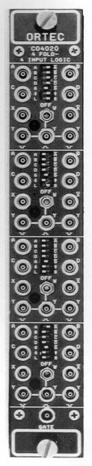
5 1. DESCRIPTION The ORTEC Model CO4020 Quad 4Input Logic Unit has the flexibility to satisfy the logic requirements of most coincidence experiments without additional logic modules. The logic functions it can perform are: coincidence (AND), anticoincidence (veto), fanin (OR), fanout, fast negative NIMtoTTL conversion, and pulse lengthening. The Model CO4020 contains four identical, independent channels of 4input logic in a singlewidth NIM module. Each of the four inputs (A, B, C, and D) accepts NIM fast negative logic pulses. Frontpanel, threeposition slide switches select the logic requirements separately for each input. The various combinations of logic functions that can be implemented are illustrated in Fig. 1 and in the specifications for the control switches. The X output is a NIM fast negative logic pulse whose width is determined by the width and overlap of the active input pulses. The complement of the X output is available at the X output. The updating Y outputs can be set to trigger on either the leading edge or the trailing edge of the X output pulse. The width of the Y outputs can be adjusted from 40 ns to 40 :s in two selectable ranges. Two of the Y outputs provide NIM fast negative logic pulses. The third Y output delivers a positive TTL logic pulse that is suitable for gating ADCs and multichannel analyzers. Frontpanel LEDs indicate which channel is generating an output. 1
6 2. SPECIFICATIONS The Model CO4020 incorporates four separate channels with identical functions. The specifications apply to each of the four channels unless stated otherwise Performance NUMBER OF IDENTICAL CHANNELS 4. MAXIMUM COUNT RATE X and X Outputs 100 MHz. Y Outputs 1/(1.1 width). MINIMUM PULSE OVERLAP 3 ns. PROPAGATION DELAY Input to X, X <8 ns. Input to Y (Neg) <13 ns. Input to Y (Pos) <20 ns. DEAD TIME OF Y OUTPUTS 110% of width setting Controls and Indicators WIDTH ADJUST (W) Frontpanel screwdriver adjustment allows width adjustment of Y outputs. Two ranges can be selected by the frontpanel slide switch: S (40!1200 ns) or L(1!40 :s). LED INDICATOR Frontpanel, red LED lights when output has been activated. CONTROL SWITCHES Frontpanel, 7 by 3position slide switch selects logic function definition, gate operation, Y output trigger point, and Y output width adjustment range as follows: Input Logic Switches (A/OFF/A,, B/OFF/B,, C/OFF/C,, D/OFF/D,, and G/OFF/G) ) As defined in Fig. 1, these switches select variations of the following basic logic functions. In the OFF position, the state of that input is ignored. With switches set to the A, B, C, D, and G positions, the module performs the OR function at the X output. Setting the switches to the A,, B,, C,, D,, and Ḡ positions provides the AND (coincidence) function at the X output. Changing the Ḡ switch to G implements the commongate veto (anticoincidence). See Fig. 1 to determine other possible logic combinations. Trigger Switch for Y Outputs (9 or 8) Allows either the negative transition (9) or the positive transition (8) of the X output to trigger the constantwidth Y outputs. Y Output Width Range Switch Sets either to L (1!40 :s) or S (40!1200 ns) Inputs A, B, C, AND D INPUTS Frontpanel LEMO connectors accept negative fastnim logic signals. Minimum Amplitude!600 mv. Minimum Width 3 ns. Input Impedance 50S. GATE INPUT (G) Frontpanel LEMO connector accepts negative FastNIM logic signals. The GATE input is delivered to all four sections. Minimum Amplitude!600 mv. Minimum Width 3 ns. Input Impedance 50S Outputs X AND XOUTPUTS Frontpanel LEMO connectors provide the noninverted (X) and the inverted (X) ) result of the logic satisfied by the input signals. Logic requirements are set by the frontpanel slide switches A/OFF/A, B/OFF/B,C/OFF/C, D/OFF/D, and G/OFF/Ḡ. X and X are FastNIM logic signals. Amplitude!20 ma. Rise Time <4 ns. Output Width Determined by duration of input signals and logic selection. 2
7 Y OUTPUTS ( AND ) Frontpanel LEMO connectors provide two updating FastNIM logic outputs ( ) and one updating positive TTL logic output ( ) per channel. Output width of all three Y outputs is set by WIDTH adjustment. Y outputs are triggered by either the negative transition (9) or positive transition (8) of the X overlap output as selected by the frontpanel slide switch Electrical and Mechanical POWER REQUIRED The Model CO4020 derives its power from a standard NIM bin and power supply. The required power is +6 V, 200 ma;!6 V, 1000 ma. WEIGHT Net 1.3 kg (2.3 lb). Shipping 2.2 kg (4.8 lb). 3. INSTALLATION After carefully unpacking the Model CO4020, thoroughly inspect it for evidence of damage in shipment. If it has been damaged, refer to the Warranty section for further instructions. The Model CO4020 operates on power from a NIM Bin/ Power Supply such as the ORTEC 4001/4002E. Always turn off the power to the power supply before inserting or removing the module. After all modules have been installed in the Bin, check the dc voltage levels from the power supply to ensure that no overload exists. The Bin and Power Supply is designed for relay rack mounting. If the equipment is rack mounted, be sure that adequate ventilation is provided to prevent any localized heating of components used in the Model CO4020. The temperature should not exceed 50 C. 4. OPERATING INSTRUCTIONS The ORTEC Model CO4020 is a Quad 4Input Logic that can be used for coincidence, anticoincidence, fanout, and to convert from a NIMstandard fast negative logic signal to a positive TTL signal. The four channels are identical, and the logic functions for each channel can be independently selected by the programming switches provided on the front panel in the form of a 7section, 3position, miniature slide switch. See Fig. 1 for logic function details Coincidence Mode ("AND" Function) For coincidence mode operation, the slide switches corresponding to the inputs that must be in coincidence must be placed to the "overlined" position (i.e., A,B,, C,, D,, or Ḡ), and the overlap output signal taken from the X output LEMO. Switches for unused inputs must be placed in the "OFF" position. If an anticoincidence condition is required for an input, place the switch for that particular input to the position which is not overlined (i.e., A, B, C, D, or G). For example, if an output is desired when a signal is present on inputs A and B and C, and no signal on D, the switches must be set to Ā, B,, C,, and D. All outputs can be gated by a NIMstandard fast negative logic signal applied to the common "Gate" input. The effects of the Gate input can be independently set for each channel by selecting the anticoincidence, OFF, or coincidence position for the G/OFF/Ḡ switch. The output signal must be taken from the X output if a NIMstandard fast negative signal is needed. If any switch is set to the "overlined" position, the output becomes the "AND" logic function of the inputs, and the X output must be used. When placed in the OFF position, switches representing the inputs disable the respective inputs so that they have no effect on the output signal "OR" Function When an "OR" function is needed, the switches representing the active inputs must be placed in the nonoverlined position (A, B, C, D, and G) or to the OFF position if not used. The output signal must be taken from the "X" output LEMO. 3
8 4.3. Outputs In addition to the overlap outputs (X), there are three outputs (Y) for each channel. Two are NIMstandard fast negative outputs ( ), and one is a positive TTL output ( ). The width of the "Y" output pulse is independently adjustable for each channel. The outputs may be triggered on the leading or trailing edge of the "X" output. The active trigger edge is selected by the /OFF/ slide switch. Since the polarity of the "X" output changes depending on the mode selected for the logic, the polarity of the leading and trailing trigger will also change. When operating in the coincidence (AND) mode, the polarity of the leading edge will be positive, but when operating in the OR mode, the polarity of the leading edge will become negative. The "OFF" position is equivalent to the positive going edge. The width of the "Y" outputs is adjustable by a frontpanel potentiometer (W) in two ranges selected by the L/OFF/S slide switch. In the "S" position the width is adjustable from 40 to 1000 ns. In the "L" position the width is adjustable from 1 to 40 :s. The "OFF" position is equivalent to the "S" range. 4
9 BIN/MODULE CONNECTOR PIN ASSIGNMENTS FOR STANDARD NUCLEAR INSTRUMENT MODULES PER DOE/ER0457T Pin Function Pin Function 1 +3 volts 23 Reserved 2 3 volts 24 Reserved 3 Spare Bus 25 Reserved 4 Reserved Bus 26 Spare 5 Coaxial 27 Spare 6 Coaxial 28* +24 volts 7 Coaxial 29* 24 volts volts dc 30 Spare Bus 9 Spare 31 Spare 10* +6 volts 32 Spare 11* 6 volts 33* 117 volts ac (Hot) 12 Reserved Bus 34* Power Return Ground 13 Spare 35 Reset (Scaler) 14 Spare 36 Gate 15 Reserved 37 Reset (Auxiliary) 16* +12 volts 38 Coaxial 17* 12 volts 39 Coaxial 18 Spare Bus 40 Coaxial 19 Reserved Bus 41* 117 volts ac (Neut.) 20 Spare 42* High Quality Ground 21 Spare G Ground Guide Pin 22 Reserved Pins marked (*) are installed and wired in ORTEC s 4001A and 4001C Modular System Bins. 5
10 6
Model 579 Fast-Filter Amplifier Operating and Service Manual
 Model 579 Fast-Filter Amplifier Operating and Service Manual Printed in U.S.A. ORTEC Part No. 733530 1202 Manual Revision C Advanced Measurement Technology, Inc. a/k/a/ ORTEC, a subsidiary of AMETEK, Inc.
Model 871 Timer and Counter Operating and Service Manual
 Model 871 Timer and Counter Operating and Service Manual Printed in U.S.A. ORTEC Part No. 733650 0503 Manual Revision E $GYDQFHG0HDVXUHPHQW7HFKQRORJ\,QF a/k/a/ ORTEC, a subsidiary of AMETEK, Inc. WARRANTY
USER INSTRUCTIONS MODEL CSI-200 COAXIAL SYSTEM INTERFACE
 USER INSTRUCTIONS MODEL CSI-200 COAXIAL SYSTEM INTERFACE 9350-7676-000 Rev B, 5/2001 PROPRIETARY NOTICE The RTS product information and design disclosed herein were originated by and are the property of
Model 974A Quad Counter/Timer Operating Manual
 ORTEC Model 974A Quad Counter/Timer Operating Manual Printed in U.S.A. ORTEC Part No. 932501 0210 Manual Revision A Advanced Measurement Technology, Inc. a/k/a/ ORTEC, a subsidiary of AMETEK, Inc. WARRANTY
Instruction Manual Model # Block Upconverter
 Instruction Manual Model 2115-278# Block Upconverter August 2018, Rev. A MODEL 2115 UPCONVERTER CROSS TECHNOLOGIES INC. EXT 10MHZ ALARM POWER Data, drawings, and other material contained herein are proprietary
Model R177M and R177S Baseband Switch
 Model R177M and R177S Baseband Switch Installation Guide P/N 1340192 082304 Monroe Electronics 100 Housel Ave Lyndonville NY 14098-0535 800-821-6001 585-765-2254 fax 585-765-9330 www.monroe-electronics.com
LEVEL ADJUST POWER Shiloh Road Alpharetta, Georgia (770) FAX (770) Toll Free
 FAX (770) Toll Free") Instruction Manual Model 1200-07 Amplifier September 2010 Rev A MONITOR J1 LEVEL ADJUST POWER MODEL 1200 AMPLIER CROSS TECHNOLOGIES, INC. Data, drawings, and other material contained herein are proprietary
Instruction Manual Model 1200-07 Amplifier September 2010 Rev A MONITOR J1 LEVEL ADJUST POWER MODEL 1200 AMPLIER CROSS TECHNOLOGIES, INC. Data, drawings, and other material contained herein are proprietary
CHECK LINE. Model LS-36-LED. Stationary Stroboscope. Operating Manual BY ELECTROMATIC
 CHECK LINE BY ELECTROMATIC Stationary Stroboscope Model LS-36-LED Operating Manual Table of Contents 1.0 Introduction... 02 1.1 Unpacking 1.2 Optional Accessories 2.0 Safety Information... 3 3.0 Controls...
TC Mbps - 622Mbps FIBER OPTIC MODE CONVERTER/REPEATER (Rev A0.1) User's Manual
 User's Manual") TC3004 50Mbps - 622Mbps FIBER OPTIC MODE CONVERTER/REPEATER (Rev A0.1) MODEL: S/N: DATE: Notice! Although every effort has been made to insure that this manual is current and accurate as of date of publication,
TC3004 50Mbps - 622Mbps FIBER OPTIC MODE CONVERTER/REPEATER (Rev A0.1) MODEL: S/N: DATE: Notice! Although every effort has been made to insure that this manual is current and accurate as of date of publication,
LEVEL ADJUST POWER Shiloh Road Alpharetta, Georgia (770) FAX (770) Toll Free
 FAX (770) Toll Free") Instruction Manual Model 1200-75 Amplifier August 2012, Rev. A LEVEL ADJUST POWER MODEL 1200 AMPLIFIER CROSS TECHNOLOGIES, INC. Data, drawings, and other material contained herein are proprietary to Cross
Instruction Manual Model 1200-75 Amplifier August 2012, Rev. A LEVEL ADJUST POWER MODEL 1200 AMPLIFIER CROSS TECHNOLOGIES, INC. Data, drawings, and other material contained herein are proprietary to Cross
Instruction Manual Model BlockUpconverter
 Instruction Manual Model 2115-55 BlockUpconverter June 2009 - Rev. 0 MODEL 2115 UPCONVERTER CROSS TECHNOLOGIES INC. EXT 10MHZ ALARM POWER Data, drawings, and other material contained herein are proprietary
Table of Contents. Introduction Pin Description Absolute Maximum Rating Electrical Specifications... 4
 Table of Contents Introduction... 1 Pin Description... 2 Absolute Maximum Rating... 3 Electrical Specifications... 4 Mechanical Specifications... 5 Thermal Specifications... 6 Over Temperature Protection...
Electronic M.O.P Card. Instruction Manual Model D
 Electronic M.O.P Card Instruction Manual Model D10341-000 Table of Contents 1. General Description................................................................ 1 2. Specifications.....................................................................
Model /29S RF Splitter
 Instruction Manual Model 1584-29/29S RF Splitter March 2013, Rev. 0 LNB VOLTAGE A B MODEL 1584 COMBINER CROSS TECHNOLOGIES INC. GND+DC ON Data, drawings, and other material contained herein are proprietary
Global Water Instrumentation, Inc.
 Instrumentation, Inc. 11390 Amalgam Way Gold River, CA 95670 T: 800-876-1172 Int l: (916) 638-3429, F: (916) 638-3270 PRODUCT NAME: 378 TEMPERATURE CONTROLLER - 1 - The model 378 is a high performance
6170 Shiloh Road Alpharetta, Georgia (770) FAX (770) Toll Free
 FAX (770) Toll Free") Instruction Manual Model 2115-202 Upconverter November 2011, Rev. C MODEL 2115 UPCONVERTER CROSS TECHNOLOGIES INC. EXT 10MHZ ALARM POWER Data, drawings, and other material contained herein are proprietary
Instruction Manual Model 2115-202 Upconverter November 2011, Rev. C MODEL 2115 UPCONVERTER CROSS TECHNOLOGIES INC. EXT 10MHZ ALARM POWER Data, drawings, and other material contained herein are proprietary
3-DRX. AUTOMATIC THREE CHANNEL DIGITAL AES/EBU REPEATER and ANALOG AUDIO SWITCHER INSTALLATION AND OPERATING MANUAL
 3-DRX AUTOMATIC THREE CHANNEL DIGITAL AES/EBU REPEATER and ANALOG AUDIO SWITCHER INSTALLATION AND OPERATING MANUAL 3-DRX SECTION 1 INTRODUCTION The TITUS TECHNOLOGICAL LABORATORIES 3-DRX AUTOMATIC THREE
Chameleon Labs Model 7720
 Chameleon Labs Model 7720 Stereo Compressor Owner s Manual 704 228 th Avenue NE, # 826 Sammamish, WA 98074 206-264-7602 www.chameleonlabs.com Revision C - December, 2007 UNPACKING AND INSPECTION Carefully
VK-P10SE WARRANTY REGISTRATION FORM
 VK-P10SE WARRANTY REGISTRATION FORM Unit Serial Number: Customer Name: Address: Date of Purchase: Purchased From: Dealer Name: Address: IMPORTANT NOTE: In order to receive the full five-year product warranty,
FTC AGL System Controller Reference Manual Part Number
 SERIAL NUMBER FTC 190-1 AGL System Controller Reference Manual Part Number 7911901 Flash Technology, 332 Nichol Mill Lane, Franklin, TN 37067 (615) 261-2000 Front Matter Abstract This manual contains information
Kramer Electronics, Ltd. USER MANUAL. Model: VA-14. 4x1 Balanced Audio Mixer
 Kramer Electronics, Ltd. USER MANUAL Model: VA-14 4x1 Balanced Audio Mixer Contents Contents 1 Introduction 1 2 Getting Started 2.1 Quick Start 1 1 3 Overview 3 4 Your VA-14 4x1 Balanced Audio Mixer 4
Installation and Operation Manual
 Installation and Operation Manual INC BOR-4 Box O Relays 4 Firmware version 1.15 and above Manual Update: 2/10/2004 Due to the dynamic nature of product design, the information contained in this document
2 FRONT PANEL CONTROLS and INDICATORS 1 TM DUC864 DIGITAL UPCONVERTER 12 POSITION RACK MOUNT POWER SUPPLY. Figure 1
 E NTE R ENTER ENTER 1 TM DIGITAL UPCONVERTER 2 FRONT PANEL CONTROLS and INDICATORS 12 POSITION RACK MOUNT SUPPLY F1 F2 TM TD8VSB 8-VSB DE TM DU C8 64 P WR / TM DU C8 64 P WR / PS8 SUPPLY SNR 23 db LOCK
EXT-3GSDI-FOSM User Manual
 EXT-3GSDI-FOSM User Manual www.gefen.com ASKING FOR ASSISTANCE Technical Support: Telephone (818) 772-9100 (800) 545-6900 Fax (818) 772-9120 Technical Support Hours: 8:00 AM to 5:00 PM PST Monday through
Model PSKIT-H540 Ultrasonic Power Supply Kit 40 khz 500 Watts
 Model PSKIT-H540 Ultrasonic Power Supply Kit 40 khz 500 Watts INSTRUCTION MANUAL Sonics & Materials, Inc. 53 Church Hill Road Newtown, CT 06470 USA 203.270.4600 800.745.1105 203.270.4610 fax www.sonics.com
AES-402 Automatic Digital Audio Switcher/DA/Digital to Analog Converter
 Broadcast Devices, Inc. AES-402 Automatic Digital Audio Switcher/DA/Digital to Analog Converter Technical Reference Manual Broadcast Devices, Inc. Tel. (914) 737-5032 Fax. (914) 736-6916 World Wide Web:
TC3005(LED/ELED/LASER) User's Manual
 User's Manual") 1. Description The gives users the ability to convert signals to format for data transmission (and vice-versa). These conversions can benefit users by extending transmission distances and/or enabling dissimilar
1. Description The gives users the ability to convert signals to format for data transmission (and vice-versa). These conversions can benefit users by extending transmission distances and/or enabling dissimilar
Warranty and Registration. Warranty: One Year. Registration: Please register your product at Port, or. or Windows.
 7 7 Port, or or Windows Port Warranty and Registration Warranty: One Year Registration: Please register your product at www.aitech.com 2007 AITech International. All rights reserved. WEB CABLE PLUS PC-TO-TV
Composite Video Extender
 Composite Video Extender EXT-COMPOSITE-141N USER MANUAL www.gefen.com ASKING FOR ASSISTANCE Technical Support: Telephone (818) 772-9100 (800) 545-6900 Fax (818) 772-9120 Technical Support Hours: 8:00 AM
INSTRUCTION MANUAL MODEL 2710 SUBCARRIER DEMODULATOR
 INSTRUCTION MANUAL MODEL 2710 SUBCARRIER DEMODULATOR Data, drawings, and other material contained herein are proprietary to Cross Technologies, Inc., and may not be reproduced or duplicated in any form
Kramer Electronics, Ltd. USER MANUAL. Model: 810B. Black Burst / Audio Generator
 Kramer Electronics, Ltd. USER MANUAL Model: 810B Black Burst / Audio Generator Contents Contents 1 Introduction 1 2 Getting Started 1 3 Your 810B Black Burst / Audio Generator 1 4 Connecting the 810B Black
DVI Rover 700 User Guide
 DVI Rover 700 User Guide Featuring ExtremeDVI Technology DVI Rover 700 This document applies to Part Numbers: 00-00106 through 00-00141 inclusive. FCC Radio Frequency Interference Statement Warning The
instruction manual model 315 video sync separator s/n
 instruction manual model 315 video sync separator s/n colorado video, inc boulder, colorado january 2016 WARNING This equipment generates, uses and can radiate radio frequency energy and if not installed
Kramer Electronics, Ltd. USER MANUAL. Model: VP-100. VGA/XGA to RGBHV Converter
 Kramer Electronics, Ltd. USER MANUAL Model: VP-100 VGA/XGA to RGBHV Converter Contents Contents 1 Introduction 1 2 Getting Started 1 2.1 Quick Start 1 3 Overview 3 4 Your VP-100 VGA/XGA to RGBHV Converter
3GSDI Fiber Optic Extender
 3GSDI Fiber Optic Extender GEF-3GSDI-FO-141 User Manual www.gefenpro.com ASKING FOR ASSISTANCE Technical Support: Telephone (818) 772-9100 (800) 545-6900 Fax (818) 772-9120 Technical Support Hours: 8:00
AES-404 Digital Audio Switcher/DA/Digital to Analog Converter
 Broadcast Devices, Inc. AES-404 Digital Audio Switcher/DA/Digital to Analog Converter Technical Reference Manual Broadcast Devices, Inc. Tel. (914) 737-5032 Fax. (914) 736-6916 World Wide Web: www.broadcast-devices.com
Kramer Electronics, Ltd. USER MANUAL. Models: TR-1YC, s-video Isolation Transformer TR-2YC, s-video Dual Isolation Transformers
 Kramer Electronics, Ltd. USER MANUAL Models: TR-1YC, s-video Isolation Transformer TR-2YC, s-video Dual Isolation Transformers Contents Contents 1 Introduction 1 2 Getting Started 1 2.1 Quick Start 1 3
High Performance, Multi-Function Nuclear Multichannel Buffer/Counter/Timer/Rate Meter Hardware Manual
 ORTEC EASY-NIM 928 Suite High Performance, Multi-Function Nuclear Multichannel Buffer/Counter/Timer/Rate Meter Hardware Manual Printed in U.S.A. ORTEC Part No. 93252 4 Manual Revision A Advanced Measurement
instruction manual Model 619YY video dual vertical line generator s/n
 instruction manual Model 619YY video dual vertical line generator s/n september 2005 WARNING This equipment generates, uses and can radiate radio frequency energy and if not installed and used in accordance
Digital Lighting Systems. DIGTAN4-PRO Converts 4 PROTOCOL channels to 4x 0.5 V to 10 VDC Analog
 Digital Lighting Systems To 0.7-10 V controlled Fixtures + -+ - + -+ - +- +- +- +- 4 TTL switches to SL408 C SW SW SW SW +5V 4 3 2 1 Out 1 Out 2 Out 3 Out 4 SW 1 SW 2 SW 3 SW 4 Switch Level adjustment
clipping; yellow LED lights when limiting action occurs. Input Section Features
 ELX-1A Rack-Mount Mic/Line Mixer Four inputs, one output in a single rack space Very-highery-high-quality audio performance High reliability Extensive filtering circuitry and shielding protect against
LIGHT COPILOT II. elationlighting.com Internet:
 LIGHT COPILOT II E-mail: info@ elationlighting.com Internet: http://www.elationlighting.com 1 Introduction Thank you for your purchase of the LIGHT COPILOT II. The LIGHT COPILOT II is an intelligent lighting
Composite Extender USER MANUAL.
 Composite Extender USER MANUAL www.gefen.com ASKING FOR ASSISTANCE Technical Support: Telephone (818) 772-9100 (800) 545-6900 Fax (818) 772-9120 Technical Support Hours: 8:00 AM to 5:00 PM Monday thru
Installation and Operation Manual. for the. SM-6 Programmable Stereo Mixer
 for the Copyright 1996 2001 by Broadcast Tools, Inc. All rights reserved. Except as permitted under the United States Copyright Act of 1976, no part of this document may be reproduced or distributed without
Kramer Electronics, Ltd. USER MANUAL. Model: VA-100P-5. Power Supply
 Kramer Electronics, Ltd. USER MANUAL Model: VA-100P-5 Power Supply Contents Contents 1 Introduction 1 2 Getting Started 1 2.1 Quick Start 1 3 Overview 2 4 Your Power Supply 3 5 Using the Power Supply 4
PSM-003. Micro Polarization Controller/Scrambler. User Guide
 PSM-003 Micro Polarization Controller/Scrambler User Guide Version: 1.0 Date: August 23, 2012 General Photonics, Incorporated is located in Chino California. For more information visit the company's website
VGA CAT-5 1:8 Distribution S VGA CAT-5 Distribution R
 VGA CAT-5 1:8 Distribution S VGA CAT-5 Distribution R EXT-VGA-CAT5-148S EXT-VGA-CAT5-148R User Manual www.gefen.com ASKING FOR ASSISTANCE Technical Support: Telephone (818) 772-9100 (800) 545-6900 Fax
Kramer Electronics, Ltd. USER MANUAL. Models: WPN-11, XGA/Component/CV/YC Transmitter WPN-12, XGA/Component/CV/YC Receiver
 Kramer Electronics, Ltd. USER MANUAL Models: WPN-11, XGA/Component/CV/YC Transmitter WPN-12, XGA/Component/CV/YC Receiver Contents Contents 1 Introduction 1 2 Getting Started 1 3 Overview 1 4 Your Component/RGB/YC/CV/XGA
User Manual TLS HDMI Switch 4/1 MHL
 875222 User Manual TLS HDMI Switch 4/1 MHL HDMI IN IR SW 4 3 2 1 OUT SBL/SBR SL/SR CEN/SUB FL/FR DIG AUDIO SPDIF DC 5V HDMI OUT 1 2 HDMI IN 3 MLH 4 8 875222 HDMI Switch 4/1 MHL Thank you for purchasing
Kramer Electronics, Ltd. USER MANUAL. Model: VM-3A. Audio Distributor
 Kramer Electronics, Ltd. USER MANUAL Model: VM-3A Audio Distributor Contents Contents 1 Introduction 1 2 Getting Started 1 2.1 Quick Start 2 3 Overview 3 4 Your Audio Distributor 4 5 Connecting Your Audio
Kramer Electronics, Ltd. USER MANUAL. Model: VM-2DVI. High Resolution / Dual Link 1:2 DVI Distributor
 Kramer Electronics, Ltd. USER MANUAL Model: VM-2DVI High Resolution / Dual Link 1:2 DVI Distributor Contents Contents 1 Introduction 1 2 Getting Started 1 2.1 Quick Start 1 3 Overview 3 4 Your VM-2DVI
560A 500 SERIES COMPRESSOR/LIMITER OWNER S MANUAL
 500 SERIES COMPRESSOR/LIMITER OWNER S MANUAL Warranty 1. Please register your product online at www.dbxpro.com. Proof-of-purchase is considered to be the responsibility of the consumer. A copy of the original
Model P/03P Upconverters
 Instruction Manual Model 2005-02P/03P Upconverters October 2013, Rev H 2005 TEST UPCONVERTER GHz 100MHz10MHz 1MHz C KU 70 140 IF IN GAIN DC POWER +DC IN +15V, 200 ma RF OUT DC ALARM LO IF FREQUENCY J1
VGA Extender LR EXT-VGA-141LR. User s Manual
 VGA Extender LR EXT-VGA-141LR User s Manual ASKING FOR ASSISTANCE Technical Support: Telephone (818) 772-9100 (800) 545-6900 Fax (818) 772-9120 Technical Support Hours: 8:00 AM to 5:00 PM Monday thru
VGAD-12 ORDERCODE
 VGAD-12 ORDERCODE 101220 Congratulations! You have bought a great, innovative product from DMT. The DMT Media Spinner brings excitement to any venue. Whether you want simple plug-&-play action or a sophisticated
Kramer Electronics, Ltd. USER MANUAL. Models: OC-1N, Video Isolator OC-2, Dual Channel Video Isolator OC-4, Quad Channel Video Isolator
 Kramer Electronics, Ltd. USER MANUAL Models: OC-1N, Video Isolator OC-2, Dual Channel Video Isolator OC-4, Quad Channel Video Isolator Contents Contents 1 Introduction 1 2 Getting Started 1 2.1 Quick Start
Extender E XT-3GSDI-FO -141 U S ER M ANUAL.
 3G-SDI Fiber Optic Extender E XT-3GSDI-FO -141 U S ER M ANUAL www.gefen.com Technical Support: Telephone (818) 772-9100 (800) 545-6900 Fax (818) 772-9120 Technical Support Hours: 8:00 AM to 5:00 PM PST
Kramer Electronics, Ltd. USER MANUAL. Model: WP-220. XGA/Audio/Video Line Driver
 Kramer Electronics, Ltd. USER MANUAL Model: WP-220 XGA/Audio/Video Line Driver Contents Contents 1 Introduction 1 2 Getting Started 1 3 Overview 1 4 Your WP-220 XGA/Audio/Video Line Driver 2 4.1 Your WP-220
LBS-1 (Lowrance Broadband Sounder)
") Pub. 988-0170-001 LBS-1 (Lowrance Broadband Sounder) Installation Instructions The LBS-1 is a digital sonar optimizer designed to enhance sonar echo clarity. The broadband sounder was created to deliver
Pub. 988-0170-001 LBS-1 (Lowrance Broadband Sounder) Installation Instructions The LBS-1 is a digital sonar optimizer designed to enhance sonar echo clarity. The broadband sounder was created to deliver
Kramer Electronics, Ltd.
 Kramer Electronics, Ltd. Preliminary USER MANUAL Model: 6241HDxl 4x1 3G HD-SDI Switcher Contents Contents 1 Introduction 1 2 Getting Started 1 2.1 Quick Start 2 3 Overview 3 4 Defining the 6241HDxl 4x1
CH1 CH2 CH3 CH4. Master /Fade CH5. 600s CH6. 60s SC1 SC2 SC4 SC3 SC5. SC6 Off/Pro. AL Fade 6 Pro. User guide
 1 1 CH1 CH2 1 1 CH4 CH 1 CH3 6s Master /Fade CH6 1 SC1 6s SC4 SC2 SC SC3 SC6 Off/Pro AL Fade 6 Pro User guide CONTENTS INTRODUCTION...2 Welcome 2 Safety 2 Supplied items 3 INSTALLATION...4 Mounting 4
Kramer Electronics, Ltd. USER MANUAL. Model: VM Video Component Distributor
 Kramer Electronics, Ltd. USER MANUAL Model: VM-1045 Video Component Distributor Contents Contents 1 Introduction 1 2 Getting Started 1 2.1 Quick Start 1 3 Overview 3 4 Your VM-1045 Video Component Distributor
SC-C1M SiriusConnect TM Vehicle Tuner
 SC-C1M SiriusConnect TM Vehicle Tuner For Special Market Applications Installation Guide Congratulations on the Purchase of your new SIRIUS SC-C1 SiriusConnect TM Vehicle Tuner. The SC-C1M is packaged
500 SERIES DE-ESSER OWNER S MANUAL
 500 SERIES DE-ESSER OWNER S MANUAL Warranty 1. Please register your product online at www.dbxpro.com. Proof-of-purchase is considered to be the responsibility of the consumer. A copy of the original purchase
Kramer Electronics, Ltd. USER MANUAL. Model: Power Amplifier
 Kramer Electronics, Ltd. USER MANUAL Model: 900 Power Amplifier Contents Contents 1 Introduction 1 2 Getting Started 1 3 Overview 1 4 Your 900 Power Amplifier 2 5 Connecting your 900 Power Amplifier 4
User Guide. Single-Link DVI Active Cable Extender. DVI-7171c
 User Guide Single-Link DVI Active Cable Extender DVI-7171c TABLE OF CONTENTS SECTION PAGE PRODUCT SAFETY...1 PRODUCT LIABILITY...1 1.0 INTRODUCTION...2 2.0 SPECIFICATIONS...3 3.0 PACKAGE CONTENTS...4 4.0
VGA Extender SRN. EXT-VGA-141SRN User Manual.
 VGA Extender SRN EXT-VGA-141SRN User Manual www.gefen.com ASKING FOR ASSISTANCE Technical Support: Telephone (818) 772-9100 (800) 545-6900 Fax (818) 772-9120 Technical Support Hours: 8:00 AM to 5:00 PM
VGA to ADC Conversion Box
 VGA to ADC Conversion Box USER MANUAL www.gefen.com Technical Support: Telephone (818) 772-9100 (800) 545-6900 Fax (818) 772-9120 Technical Support Hours: 8:00 AM to 5:00 PM Monday through Friday PST Write
USER MANUAL. Kramer Electronics, Ltd. Models:
 Kramer Electronics, Ltd. USER MANUAL Models: 707, Video Audio Line Transmitter 708, Video Audio Line Receiver 709, Y/C Line Transmitter 710, Y/C Line Receiver 711xl, Video-Audio Line Transmitter 712xl,
Kramer Electronics, Ltd. USER MANUAL. Model: WP-210A. XGA/Audio Line Driver
 Kramer Electronics, Ltd. USER MANUAL Model: WP-210A XGA/Audio Line Driver Contents Contents 1 Introduction 1 2 Getting Started 1 3 Overview 1 4 Your WP-210A XGA/Audio Line Driver 2 4.1 Your WP-210A Front
Operating Instructions
 Operating Instructions SteadiQ 2009-351 Read This Manual before You Attempt to use this Instrument WARNING: Dangerous Voltages Present - NO Serviceable Parts Inside Instrument should be serviced by qualified
OPTICA TECHNOLOGIES INCORPORATED and the OPTICA TECHNOLOGIES INCORPORATED logo are trademarks of Optica Technologies Incorporated.
 Optica Technologies Incorporated 34600 FXBT Converter Quick Start Guide Product Warranty Safety Warnings 34600/070208 Trademarks OPTICA TECHNOLOGIES INCORPORATED and the OPTICA TECHNOLOGIES INCORPORATED
MLA-XLR MIDI Line Amplifier
 MIDI Line Amplifier Users Manual , and 0 are trademarks of JLCooper Electronics. All other brand names are the property of their respective owners. User s Manual, First Edition Part Number 932090 2002
Please take a few minutes to read this manual so that you will better understand the featues and capabilities of your MF80. MF80 Owner s Manual 1
 Congratulations on your purchase of the Conrad-Johnson MF80 amplifier. You have acquired one of the finer pieces of musical reproduction equipment available today. The MF80 is the result of over a decade
instruction manual model 307 horizontal video caliper
 instruction manual model 307 horizontal video caliper s/n COLORADO VIDEO, INC BOULDER, COLORADO August 1996 Rev Apr 98 WARNING This equipment generates, uses and can radiate radio frequency energy and
Kramer Electronics, Ltd. USER MANUAL. Models: PT-102AN, 1:2 Audio DA PT-102SN, 1:2 s-video DA
 Kramer Electronics, Ltd. USER MANUAL Models: PT-102AN, 1:2 Audio DA PT-102SN, 1:2 s-video DA Contents Contents 1 Introduction 1 2 Getting Started 1 2.1 Quick Start 1 3 Overview 3 3.1 About the PT102AN
SDM-871p. SDM-871p. HD Serial Digital Component Analog Video Converter. Guide to Installation and Operation M
 picolink Series SDM-871p Guide to Installation and Operation M277-9900-101 Copyright 2002 Miranda Technologies Inc. Specifications may be subject to change. Printed in Canada August 2002 Miranda Technologies
BISON 500 USER'S MANUAL. IGS Audio Igor Sobczyk 3 Maja 76d, Mysłowice, Poland ph:
 BISON 500 USER'S MANUAL IGS Audio Igor Sobczyk 3 Maja 76d, 41-400 Mysłowice, Poland e-mail: igs@o2.pl ph: +48 601 597 592 www.igsaudio.com Please read all of the following instructions and save them or
USER MANUAL. Kramer Electronics, Ltd. Models:
 Kramer Electronics, Ltd. USER MANUAL Models: 103AV, 1:3 Audio-Stereo / Video DA 104M, 1:4 Microphone Amplifier 105A, 1:5 Stereo Audio DA 105S, 1:5 High Resolution s-video DA 105V, 1:5 High Resolution Video
Kramer Electronics, Ltd. USER MANUAL. Model: VP-41. 4x1 VGA / XGA Switcher
 Kramer Electronics, Ltd. USER MANUAL Model: VP-41 4x1 VGA / XGA Switcher Contents Contents 1 Introduction 1 2 Getting Started 1 3 Overview 1 4 Your VP-41 4x1 VGA / XGA Switcher 2 5 Connecting the VP-41
APSPB PUSH BUTTON ZERO Installation Manual
 APSPB PUSH BUTTON ZERO Installation Manual CARDINAL SCALE MFG. CO. 8527-0579-0M Rev A 203 E. Daugherty, Webb City, MO 64870 USA Printed in USA 12/14 Ph: 417-673-4631 Fax: 417-673-2153 www.detectoscale.com
CardModule. Reference Manual. Series C DA Channel SDI to CVBS Converter. Version 1.0
 Reference Manual C DA 5005 5 Channel SDI to CVBS Converter Version 1.0 Series 5000 CardModule LYNX Technik AG Brunnenweg 3 D-64331 Weiterstadt Germany www.lynx-technik.com Information in this document
instruction manual x-y indicator model 620D
 instruction manual x-y indicator model 620D s/n boulder, colorado WARNING This equipment generates, uses and can radiate radio frequency energy and if not installed and used in accordance with the instruction
Installation and Operation Manual
 PROBLEM SOLVED Installation and Operation Manual INC AES DA 2x6 Six-output, two-input AES/EBU Digital Audio Distribution Amplifier Manual update: 9/17/2015 If you need a firmware upgrade, contact Broadcast
Distribution Unit. User Guide
 Distribution Unit User Guide CONTENTS 1. Introduction Page 2 2. Technical Specifications Page 3 3. Installation 3.1 Inspection and un-packing Page 4 3.2 Operating environment Page 4 3.3 Power requirements
OPERATOR'S MANUAL MODEL CHANNEL TIME STRETCHER
 OPERATOR'S MANUAL MODEL 1275 16-CHANNEL TIME STRETCHER 1 Corporate Headquarters 700 Chestnut Ridge Road Chestnut Ridge, NY 10977-6499 Tel: (914) 578-6013 Fax: (914) 578-5985 E-mail: lrs_sales@lecroy.com
DUAL/QUAD DISPLAY CONTROLLER Operation Manual
 DUAL/QUAD DISPLAY CONTROLLER Operation Manual Model PXD524 MicroImage Video Systems division of World Video Sales Co., Inc PO Box 331 Boyertown, PA 19512 Phone 610-754-6800 Fax 610-754-9766 sales@mivs.com
Kramer Electronics, Ltd. USER MANUAL. Model: PT-102VN. 1:2 Video DA
 Kramer Electronics, Ltd. USER MANUAL Model: PT-102VN 1:2 Video DA Contents Contents 1 Introduction 1 2 Getting Started 1 2.1 Quick Start 2 3 Overview 3 4 Your PT-102VN 1:2 Video DA 4 5 Using the PT-102VN
LavryBlack Series Model DA10 Digital to Analog Converter
 LavryBlack Series Model DA10 Digital to Analog Converter Lavry Engineering, Inc. P.O. Box 4602 Rolling Bay, WA 98061 http://lavryengineering.com email: techsupport@lavryengineering.com January 14, 2008
AES Channel Digital/Analog Audio Switcher/DA/Digital to Analog Converter
 Broadcast Devices, Inc. AES-408 8 Channel Digital/Analog Audio Switcher/DA/Digital to Analog Converter Technical Reference Manual Broadcast Devices, Inc. Tel. (914) 737-5032 Fax. (914) 736-6916 World Wide
INSTRUCTION MANUAL MODEL IEC-788 NTSC/PAL, F1/F2, S-VHS CLOSED CAPTION DECODER
 INSTRUCTION MANUAL MODEL IEC-788 NTSC/PAL, F1/F2, S-VHS CLOSED CAPTION DECODER LINK ELECTRONICS, INC. 2137 Rust Avenue Cape Girardeau, Missouri 63703 Phone: 573-334-4433 Fax: 573-334-9255 e-mail: sales
Model Number Structure
 Cycle Control Units CSM DS_E_7_1 Refer to Safety Precautions for All Power Controllers. Used in Combination with the to Enable High-precision Temperature Control Use cycle control to achieve power control
Kramer Electronics, Ltd. USER MANUAL. Model: PT-101HDCP. DVI Repeater
 Kramer Electronics, Ltd. USER MANUAL Model: PT-101HDCP DVI Repeater Contents Contents 1 Introduction 1 2 Getting Started 1 2.1 Quick Start 1 3 Overview 3 3.1 About HDCP 3 3.2 Recommendations for Best Performance
USER MANUAL. MODEL 460RC Rack-Mounted G.703 Coax to Twisted Pair Adapters (BALUNs)
") USER MANUAL MODEL 460RC Rack-Mounted G.70 Coax to Twisted Pair Adapters (BALUNs) An ISO-900 Certified Company Part # 07M460RC-A Doc. #0908UA Revised //98 SALES OFFICE (0) 975-000 TECHNICAL SUPPORT (0)
USER MANUAL MODEL 460RC Rack-Mounted G.70 Coax to Twisted Pair Adapters (BALUNs) An ISO-900 Certified Company Part # 07M460RC-A Doc. #0908UA Revised //98 SALES OFFICE (0) 975-000 TECHNICAL SUPPORT (0)
8024-DSS-02 Issue 2. DSS-8024 Dual Serial Switch USER MANUAL
 8024-DSS-02 Issue 2 DSS-8024 Dual Serial Switch USER MANUAL DSS-8024 Dual Serial Switch User Manual Ross Part Number: 8024-DSS-02 Document Issue: 2 Printing Date: March 15, 2000. Printed in Canada. The
Kramer Electronics, Ltd. USER MANUAL. Model: VS-211HDxl. 3G HD-SDI Automatic Standby Switcher
 Kramer Electronics, Ltd. USER MANUAL Model: VS-211HDxl 3G HD-SDI Automatic Standby Switcher Contents Contents 1 Introduction 1 2 Getting Started 1 2.1 Quick Start 2 3 Overview 3 4 Your VS-211HDxl 3G HD-SDI
INSTALLATION AND OPERATION MANUAL
 INSTALLATION AND OPERATION MANUAL for the Broadcast Tools 6 x 1 Six Input, Single Output Stereo Switcher/Router Broadcast Tools is a registered trademark of Copyright 1994-2002 by All rights reserved.
VGA Extender LR EXT-VGA-141LR. User s Manual
 VGA Extender LR EXT-VGA-141LR User s Manual Congratulations on your purchase of the VGA Extender LR. Your complete satisfaction is very important to us. Gefen Gefen delivers innovative, progressive computer
4X1 Gefen TV Switcher. GTV-HDMI User Manual
 4X1 Gefen TV Switcher GTV-HDMI1.3-441 User Manual www.gefentv.com ASKING FOR ASSISTANCE Technical Support: Telephone (818) 772-9100 (800) 545-6900 Fax (818) 772-9120 Technical Support Hours: 8:00 AM to
4X1 Gefen TV Switcher GTV-HDMI N. User Manual
 4X1 Gefen TV Switcher GTV-HDMI1.3-441N User Manual INTRODUCTION Congratulations on your purchase of the 4x1 GefenTV Switcher. Your complete satisfaction is very important to us. GefenTV GefenTV is a unique