GALILEO Timing Receiver
|
|
|
- Matilda Collins
- 5 years ago
- Views:
Transcription


1 GALILEO Timing Receiver The Space Technology GALILEO Timing Receiver is a triple carrier single channel high tracking performances Navigation receiver, specialized for Time and Frequency transfer application. It is a core derivative of a multi-channel GNSS receiver developed originally for the GALILEO SIS ICD 12.0 standard. Current version of GALILEO Receiver core has been upgraded for the Timing Receiver implementation, to SIS ICD 13.2 for supporting the L1 CBOC extended mode and E6 carrier. The GALILEO Timing receiver for the E5 signal implements the AltBOC coherent demodulation. The design is based on COTS latest generation digital IF processor equipped with wideband ADC and DAC Board supported by an FPGA of the most recent generation and state of art CMOS geometry (CMOS 40 nm). Receiver Assembling The receiver can be provided in two different assembling formats: stand alone 19-1U case rack mounted 3U/6U Board set When used as standalone Unit the 19-1U Receiver assembling is complete of AC-DC adapter, fan coolers and internal high quality reference oscillator. Alternatively when used as set of rack mounted 3U/6U Board external reference oscillator and proper DC power supplying system and clock references must be provided. For what concern the stand alone 19-1U case assembled unit, Fig. 1 reports the front panel of the Timing Receiver case, while Fig. 2 reports the rear panel. Fig. 1 Fig. 2
2 For the rack mounted assembling solution, the number and type of Boards (3U/6U) will be described after the Factory Receiver configuration will be introduced (see Receiver Configurations Paragraph). Receiver I/O interfaces Fig. 3 reports a description of the interface provided by the Timing Receiver. USB MHz input clock 1PPS input 10.00MHz ref clock Time input 10.23MHz Recovered Sine Carrier (DDS) 3 Timing Receiver Int. Ref. Osc. 1PPS output Demodulated Page 6 Observable serial output 6 output clock Loop Monitoring (LVDS) Fig. 3 The Timing Receiver is provided with a GUI aimed at configuring and monitoring the receiver using an external PC linked through a USB 2.0 interface channel. Actually only one of the two foreseen USB interface is currently enabled. A GPS L1 receiver module developed by Space Technology (and the associated configuration USB channel 2) is foreseen in the Timing Receiver product evolution, for supporting an accurate measurement and monitoring of the Galileo to GPS Offset Time (GGTO) or of the EGNOS to GPS Offset Time (EGTO) assuming an external Atomic Reference and a Time Event Counting measurement system with accuracy below 1 tenth of ns is provided externally to the Timing Receiver. The monitoring interfaces are split in two main sections: an host PC interface section allowing to handle navigation algorithm with log data threads that are transmitted within 1PPS frame but that are floating w.r.t. the HW received 1PPS signal depending on the response of the SW.
3 a real time interface aimed for accurate Time and Frequency implementation in which the main observable of the Timing Receiver are available on a set of digital line interfaces below described. The following interface signals (Table 1) for clock and time measurement and receiver status monitoring are provided. Signals Panel Description L1-GAL RF/IF input Front L1-GAL Analog IF interface ( MHz) or L1-GAL Analog RF interface depending on the purchased option E5-GAL RF/IF input Front E5-GAL Analog IF interface ( MHz) or E5-GAL Analog RF interface depending on the purchased option E6-GAL RF/IF input Front E6-GAL Analog IF interface ( MHz) or E6-GAL Analog RF interface depending on the purchased option L1-GPS RF/IF input Front Currently not enabled L1-GAL IF output Front L1-GAL down converted monitoring output. Factory enabled only if any of the RF interface option is purchased. E5-GAL IF output Front E5-GAL down converted monitoring output. Factory enabled only if any of the RF interface option is purchased. E6-GAL IF output Front E6-GAL down converted monitoring output. Factory enabled only if any of the RF interface option is purchased. L1-GAL IF output Front Currently not enabled GAL USB 1 interface Front Monitoring PC interface USB 2.0 GPS USB 2 interface Front Currently not enabled 10.00MHz clock in Rear External 10.00MHz clock reference used when the receiver is SW configured to accept it to synchronize the internal 10.23MHz OCXO to an external time reference system MHz clock in Rear External 10.23MHz clock reference used when the receiver is SW configured to accept it. It completely replace the internal 10.23MHz OCXO mostly for test and debugging purposes. Output clock Rear Internal 10.23MHz OCXO clock reference. Such output will report in case either the external 10.00MHz or the internal 10.23MHz reference clock is selected, the output of the internal 10.23MHz OCXO. In case the external 10.23MHz will be selected and applied to the Timing Receiver, this signal will simply report a buffered replica of the external 10.23MHz input clock. 1 PPS input Rear This signal is the external 1PPS synchronization input. Is active high and it is supposed to be externally synchronous with the external 10.00MHz clock rising edge. 1 PPS output Rear This signal is the external 1 PPS synchronization output. It is active high and it is supposed to be internally synchronous with the OCXO 10.23MHz reference OCXO Oscillator. Time serial input Rear It is a digital signal strobing synchronously with the 1 PPS strobe and the external 10.00MHz input clock the 32 bits of the GALILEO Receiver Time. Such a Time when not critical can be set via the USB link or being overwritten by one of the Demodulated Page Message fields (one of the three option is configurable via SW GUI). Demodulated Page Rear Digital Demodulated Page Message (0..5) representing in sequence L1A, Messages (0.. 5) L1B,E5A,E5B,E6A and E6B). Such signals are synchronous with the 1 PPS output going active High (First Page Message bit) and with the rising edge of the output clock (first and all the Page Demodulated bits).
4 Observable Output (0.. 5) Serial Loop Monitoring (0.. 9) 10.23MHz recovered carriers (0..2) SERDES Monitoring(1..6) Rear Rear Rear Rear Code phase offset, Carrier phase residual offset, Frequency residual offset, Start of Frame Offset, Fine code error are serially transmitted for each of the three GAL carrier using an enable strobe synchronously with the output clock DLL code error and PLL carrier phase error plus symbol clock for each of the three GAL carriers 10.23MHz sine carriers regenerated using the estimated carrier frequency error and a Direct Digital Synthesis technique applied to an internal dedicated NCO. These are 5Gbps links (each of the 6 SERDES output) aimed at monitoring at very high rate internal Receiver state variable. They require a receiver compatible with ALTERA Stratix 4 FPGA SERializer DESerializer interface. Therefore 10Gbps per carrier Monitoring could be allocated. Table 1 Additional Test Connector pins could customized, upon request, using Test Connector 3 and 4. Receiver Configurations The receiver is a high quality acquisition and tracking receiver aimed for Ground Segment control of a GALILEO GNSS SV. It allows acquiring and tracking a single SV because of the accuracy implied and the density of its real time output interfaces. Therefore the Timing Receiver has been actually conceived as Ground Segment receiver for Down Link one way Frequency and Time Transfer implementation when properly driven by an external 10.00MHz Atomic Clock Reference an external and accurate Time Interval Counting machine with time resolution greater than the GALILEO system time The receiver can be ordered with the following configuration: IF MHz input only. This configuration is aimed at completely validating the Receiver when the SIS Generator does not provide the RF up-converter signal in L band but only analog IF signal in the 140MHz range domain (143.22MHz). RF instrumental input only. This configuration is aimed at testing the Receiver when the SIS Generator provide the RF up-converter signal in L band at power level in the range from -20dBm down to -40dBm (i.e. much higher power level than SIS level guaranteed on Ground).
5 RF antenna ready input only. This configuration is aimed to test the Receiver when input signal is compliant with RF power levels guaranteed by GALILEO SIS on ground (in the range of -120dBm) Fig. 1 and Fig. 2 reports the stand alone assembling for the complete solution up to RF antenna ready configuration. For the Timing Receiver Rack Mounted version. according to which option is selected the following Boards will be needed: IF input only: Two digital IF 3U Boards each being of 3U form factor (1.0 6U slot) RF instrumental input: Two digital IF 3U Boards and 1 triple carrier receiver RF down converter. Each of them is based on a 3U form factor (1.5 6U slot) RF antenna ready input: Two digital IF 3U Boards and one 6U triple carrier antenna ready RF receiver and down converter. Each of them is based on a 3U form factor (2.0 6U slot) In any case for the Rack Mounted version, independently from which version is purchased, the external clock references (for both Base Band and RF/IF front ends) shall be provided externally, together with proper DC power supplier (Voltage Current and Power Supply Ripple wise). Main Functional & Performance characteristics The main Functional and Performance characteristic are reported in Table 2. Specification Value Note Number of simultaneously Demodulated RF carrier 3 GALILEO L1, E5 and E6 Number of Demodulated Space Vehicles per carrier *) 1 Interface I/O limited see Note 1 Minimum Acquisition C/N0 35dB-Hz RF Demodulator LNA Noise Figure 2.8 db RF Front end without Antenna Noise Figure 3.2 db (0.4 db filter & cables loss) RF Front end without Antenna max Input signal, -40 dbm linear operation RF Front end without Antenna absolute Max Input 0 dbm signal: Max RF Front gain end without Antenna Gain, (RF Input to BB analog out) 76.5 db 47 db RF Direct Demodulator LNA & Filters Analog AGC control range 30dB +10dB 20dB. Noise level, BB analog output any channel (max gain) KHz BW I,Q,I-,Q- (without Antenna Front End) Noise level, BB analog output any channel (max gain) -19 dbm wideband I,Q,I-,Q- (without Antenna Front End) Internal reference 10.23MHz OCXO Y Selectable via GUI External synchronization to 10.23MHz LO Y Selectable via GUI External synchronization to 10.00MHz LO Y Selectable via GUI
6 10.23MHz OCXO Integrated Phase Noise rad Frequency integration interval [ E4] Hz (see Note 2 ) RF Carrier Integrated Phase Noise rad Frequency integration interval [ E4] Hz Digital AFC Loop BW programmable Y Digital DLL Loop BW programmable Y Digital PLL Loop BW programmable Y Digital AFC Loop Order First Digital DLL Loop Order First Carrier Aided Digital PLL Loop BW programmable Second Coherent Phase Error Detector Standard Deviation DLL Synchronizer error on AWGN 45dB-Hz 0.5 ns BW = 0.05 Hz with Carrier Aiding being enabled and no dynamic stress error (still Standard Deviation PLL Synchronizer error on AWGN 45dB-Hz Standard Deviation AFC+PLL Synchronizer error on AWGN 45dB-Hz receiver) 0.1 degree BW = 0.1 Hz with arctangent coherent error detector and no dynamic stress error (still receiver) 0.1Hz BW = 0.1 Hz PLL second order with AFC disabled after PLL setting with arctangent coherent error detector and no dynamic stress error (still receiver) PC Monitoring and Setting Interface USB 2.0 Two USB interface are foreseen one for the GALILEO configuration and one for the GPS configuration. The GPS one is currently not enabled. PC RX Monitoring and Setting GUI Y O.S. Window XP PC RX Monitoring and Setting Driver Y.DLL file to be linked in Visual C++ (Windows XP) Table 2 1 Natively it would be 12 per carrier. The Timing receiver limitation to single SV comes from the I/O real time interface connectors 2 Below (Table 3) the Integrated Phase Noise calculation starting from a 10.00MHz OCXO low phase noise raw data (from OCXO data-sheet) Table 3
 via a SW GUI some of the internal design variable (I, Q demodulated symbols, Error variable for DLL, PLL and AFC etc.")
7 Monitoring customization The Timing Receiver is a fully observable receiver conceived with an internal Buffering system aimed at observing in Burst Mode (up to the Buffer saturation and then repeated in time after dumping on the Monitoring PC) via a SW GUI some of the internal design variable (I, Q demodulated symbols, Error variable for DLL, PLL and AFC etc.) or in real time (real time continuous) via parallel digital connector directly connected to an FPGA Base Band receiver Test Multiplexer. The Test Multiplexer can be controlled by the User via the Timing Receiver GUI. In some other specific cases, additional SQM (Signal Quality Monitoring) variable could be ad-hoc specified by the Customer, and directly implemented inside the FPGA Base Band Receiver, if they cannot be processed directly via SW elaboration due to the involved processing rate. As example of such customization below are reported the results of the RX tracking phase of L1B being observed internally to the FPGA, through the internal primary code accumulator signal. The Waveform below reported, is taken directly from Tektronix Logic Analyzer (LA) connected to the Digital Test Connectors 3 and 4 and ultimately to the FPGA Test Multiplexer. Fig. 4 Fig. 5 for example reports an acquisition (through Logic Analyzer during the Receiver tracking phase) of the FPGA internal L1B and L1C Despreader accumulator time evolution. The top Logic Analyzer waveform in Fig. 5 shows the FPGA L1B (data channel) internal despreader accumulator, while the bottom waveform of Fig. 5 reports the L1C (pilot channel) despreader accumulator. Note that in this case the code phase set by the Receiver is the same (like in a single DLL receiver) showing that L1B and L1C are fully synchronous and aligned.
8 As expected, the L1C pilot epoch is 25 times the L1B code epoch. The Timing Receiver is equipped with a SW GUI (Fig. 7) capable of monitoring by time intervals: loop error signals, scattering diagram of the Demodulated symbols as well as to provide the Navigation message pages and their main decoded fields (Fig. 9), the CRC error (if any) plus the elapsed time. Fig. 5 Below in Fig. 6, the scattering diagram of L1B signal (I,Q) is shown after the symbol have been despreaded and carrier recovered.

9 Fig. 6 Fig. 7
10 It is also possible to appreciate the slight degradation introduced by the Timing Receiver RF front end comparing the L1B scattering diagram interfacing the receiver using a GALILEO SIS Generator at RF instrumental (not in the antenna ready mode) or at IF level. See Fig. 8. Fig. 8 Finally the GUI and Timing Receiver interact to provide log files of the demodulated message pages. Below in Fig. 9 we report the L1B Navigation Monitor file report elaborated by the Timing Receiver GUI when the Receiver is tracking in real time. All the L1B message fields are decoded and reported as they are demodulated by the RF and Base Band receiver front ends.
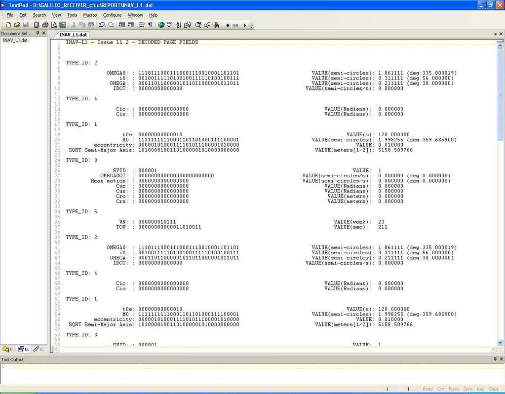
11 Fig. 9
AR SWORD Digital Receiver EXciter (DREX)
") Typical Applications Applied Radar, Inc. Radar Pulse-Doppler processing General purpose waveform generation and collection Multi-channel digital beamforming Military applications SIGINT/ELINT MIMO and
Typical Applications Applied Radar, Inc. Radar Pulse-Doppler processing General purpose waveform generation and collection Multi-channel digital beamforming Military applications SIGINT/ELINT MIMO and
Synthesized Clock Generator
 Synthesized Clock Generator CG635 DC to 2.05 GHz low-jitter clock generator Clocks from DC to 2.05 GHz Random jitter
MULTIDYNE INNOVATIONS IN TELEVISION TESTING & DISTRIBUTION DIGITAL VIDEO, AUDIO & DATA FIBER OPTIC MULTIPLEXER TRANSPORT SYSTEM
 MULTIDYNE INNOVATIONS IN TELEVISION TESTING & DISTRIBUTION INSTRUCTION MANUAL DVM-1000 DIGITAL VIDEO, AUDIO & DATA FIBER OPTIC MULTIPLEXER TRANSPORT SYSTEM MULTIDYNE Electronics, Inc. Innovations in Television
QUICK START GUIDE FOR DEMONSTRATION CIRCUIT /12/14 BIT 10 TO 105 MSPS ADC
 LTC2280, LTC2282, LTC2284, LTC2286, LTC2287, LTC2288 LTC2289, LTC2290, LTC2291, LTC2292, LTC2293, LTC2294, LTC2295, LTC2296, LTC2297, LTC2298 or LTC2299 DESCRIPTION Demonstration circuit 851 supports a
SingMai Electronics SM06. Advanced Composite Video Interface: HD-SDI to acvi converter module. User Manual. Revision 0.
 SM06 Advanced Composite Video Interface: HD-SDI to acvi converter module User Manual Revision 0.4 1 st May 2017 Page 1 of 26 Revision History Date Revisions Version 17-07-2016 First Draft. 0.1 28-08-2016
HP 71910A and 71910P Wide Bandwidth Receiver Technical Specifications
 HP 71910A and 71910P Wide Bandwidth Receiver Technical Specifications 100 Hz to 26.5 GHz The HP 71910A/P is a receiver for monitoring signals from 100 Hz to 26.5 GHz. It provides a cost effective combination
National Park Service Photo. Utah 400 Series 1. Digital Routing Switcher.
 National Park Service Photo Utah 400 Series 1 Digital Routing Switcher Utah Scientific has been involved in the design and manufacture of routing switchers for audio and video signals for over thirty years.
QUICK START GUIDE FOR DEMONSTRATION CIRCUIT /12/14 BIT 10 TO 65 MSPS DUAL ADC
 LTC2286, LTC2287, LTC2288, LTC2290, LTC2291, LTC2292, LTC2293, LTC2294, LTC2295, LTC2296, LTC2297, LTC2298 or LTC2299 DESCRIPTION Demonstration circuit 816 supports a family of s. Each assembly features
PEP-II longitudinal feedback and the low groupdelay. Dmitry Teytelman
 PEP-II longitudinal feedback and the low groupdelay woofer Dmitry Teytelman 1 Outline I. PEP-II longitudinal feedback and the woofer channel II. Low group-delay woofer topology III. Why do we need a separate
Model 7330 Signal Source Analyzer Dedicated Phase Noise Test System V1.02
 Model 7330 Signal Source Analyzer Dedicated Phase Noise Test System V1.02 A fully integrated high-performance cross-correlation signal source analyzer from 5 MHz to 33+ GHz Key Features Complete broadband
Noise Detector ND-1 Operating Manual
 Noise Detector ND-1 Operating Manual SPECTRADYNAMICS, INC 1849 Cherry St. Unit 2 Louisville, CO 80027 Phone: (303) 665-1852 Fax: (303) 604-6088 Table of Contents ND-1 Description...... 3 Safety and Preparation
Introduction This application note describes the XTREME-1000E 8VSB Digital Exciter and its applications.
 Application Note DTV Exciter Model Number: Xtreme-1000E Version: 4.0 Date: Sept 27, 2007 Introduction This application note describes the XTREME-1000E Digital Exciter and its applications. Product Description
Datasheet SHF A
 SHF Communication Technologies AG Wilhelm-von-Siemens-Str. 23D 12277 Berlin Germany Phone +49 30 772051-0 Fax ++49 30 7531078 E-Mail: sales@shf.de Web: http://www.shf.de Datasheet SHF 19120 A 2.85 GSa/s
Implementing Audio IP in SDI II on Arria V Development Board
 Implementing Audio IP in SDI II on Arria V Development Board AN-697 Subscribe This document describes a reference design that uses the Audio Embed, Audio Extract, Clocked Audio Input and Clocked Audio
Technical Data. HF Tuner WJ-9119 WATKINS-JOHNSON. Features
 May 1996 Technical Data WATKINS-JOHNSON HF Tuner WJ-9119 WJ designed the WJ-9119 HF Tuner for applications requiring maximum dynamic range. The tuner specifically interfaces with the Hewlett-Packard E1430A
MDVBS SPECIFICATION COMTECH TECHNOLOGY CO., LTD. DVBS TUNER Revision:1.0
 1.SCOPE The supports QPSK in DIRECTV and DVB-S legacy transmission (1 to 45 Mbauds), plus 8PSK in DVB-S2 transmissions (1 to 45 Mbauds). DVB-S2 demodulation uses robust symbols probust by the transmission
Nutaq. PicoDigitizer-125. Up to 64 Channels, 125 MSPS ADCs, FPGA-based DAQ Solution With Up to 32 Channels, 1000 MSPS DACs PRODUCT SHEET. nutaq.
 Nutaq Up to 64 Channels, 125 MSPS ADCs, FPGA-based DAQ Solution With Up to 32 Channels, 1000 MSPS DACs PRODUCT SHEET QUEBEC I MONTREAL I N E W YO R K I nutaq.com Nutaq The PicoDigitizer 125-Series is a
7000 Series Signal Source Analyzer & Dedicated Phase Noise Test System
 7000 Series Signal Source Analyzer & Dedicated Phase Noise Test System A fully integrated high-performance cross-correlation signal source analyzer with platforms from 5MHz to 7GHz, 26GHz, and 40GHz Key
Major Differences Between the DT9847 Series Modules
 DT9847 Series Dynamic Signal Analyzer for USB With Low THD and Wide Dynamic Range The DT9847 Series are high-accuracy, dynamic signal acquisition modules designed for sound and vibration applications.
SingMai Electronics SM06. Advanced Composite Video Interface: DVI/HD-SDI to acvi converter module. User Manual. Revision th December 2016
 SM06 Advanced Composite Video Interface: DVI/HD-SDI to acvi converter module User Manual Revision 0.3 30 th December 2016 Page 1 of 23 Revision History Date Revisions Version 17-07-2016 First Draft. 0.1
DSM GHz Linear Chirping Source
 DSM202 2.0 GHz GENERAL DESCRIPTION The DSM202 is a linear chirping waveform module that generates two types of chirping waveforms at 32 clocks per frequency update. The DSM202 can be controlled using a
DATUM SYSTEMS Appendix A
 DATUM SYSTEMS Appendix A Datum Systems PSM-4900 Satellite Modem Technical Specification PSM-4900, 4900H and 4900L VSAT / SCPC - Modem Specification Revision History Rev 1.0 6-10-2000 Preliminary Release.
Lab 1 Introduction to the Software Development Environment and Signal Sampling
 ECEn 487 Digital Signal Processing Laboratory Lab 1 Introduction to the Software Development Environment and Signal Sampling Due Dates This is a three week lab. All TA check off must be completed before
LMH0340/LMH0341 SerDes EVK User Guide
 LMH0340/LMH0341 SerDes EVK User Guide July 1, 2008 Version 1.05 1 1... Overview 3 2... Evaluation Kit (SD3GXLEVK) Contents 3 3... Hardware Setup 4 3.1 ALP100 BOARD (MAIN BOARD) DESCRIPTION 5 3.2 SD340EVK
FREQUENCY CONVERTER. MULTIPLE OUTPUT WIDEBAND Ku AND Ka DOWNCONVERTERS. Narda-MITEQ FEATURES OPTIONS
 MULTIPLE OUTPUT WIDEBAND Ku AND Ka DOWNCONVERTERS FEATURES Small weather resistant enclosure Automatic 5/10 MHz internal/external reference selection 10/100 Base-T Ethernet and RS-485/RS-422 remote control
VXI RF Measurement Analyzer
 VXI RF Measurement Analyzer Mike Gooding ARGOSystems, Inc. A subsidiary of the Boeing Company 324 N. Mary Ave, Sunnyvale, CA 94088-3452 Phone (408) 524-1796 Fax (408) 524-2026 E-Mail: Michael.J.Gooding@Boeing.com
Model 5240 Digital to Analog Key Converter Data Pack
 Model 5240 Digital to Analog Key Converter Data Pack E NSEMBLE D E S I G N S Revision 2.1 SW v2.0 This data pack provides detailed installation, configuration and operation information for the 5240 Digital
DIGITAL INSTRUMENTS S.R.L. SPM-ETH (Synchro Phasor Meter over ETH)
") DIGITAL INSTRUMENTS S.R.L. SPM-ETH (Synchro Phasor Meter over ETH) SPM-ETH (Synchro Phasor Meter over ETH) Digital Instruments 1 ver the years, an awareness of the criticality of the Power Grid and Orelated
DIGITAL INSTRUMENTS S.R.L. SPM-ETH (Synchro Phasor Meter over ETH) SPM-ETH (Synchro Phasor Meter over ETH) Digital Instruments 1 ver the years, an awareness of the criticality of the Power Grid and Orelated
SignalTap Plus System Analyzer
 SignalTap Plus System Analyzer June 2000, ver. 1 Data Sheet Features Simultaneous internal programmable logic device (PLD) and external (board-level) logic analysis 32-channel external logic analyzer 166
A MISSILE INSTRUMENTATION ENCODER
 A MISSILE INSTRUMENTATION ENCODER Item Type text; Proceedings Authors CONN, RAYMOND; BREEDLOVE, PHILLIP Publisher International Foundation for Telemetering Journal International Telemetering Conference
White Paper Lower Costs in Broadcasting Applications With Integration Using FPGAs
 Introduction White Paper Lower Costs in Broadcasting Applications With Integration Using FPGAs In broadcasting production and delivery systems, digital video data is transported using one of two serial
1Chapter INTRODUCTION. This chapter describes the CST-5000 C-Band satellite terminal, referred to in this manual as the CST-5000 (Figure 1-1).
.") 1Chapter 1. INTRODUCTION This chapter describes the CST-5000 C-Band satellite terminal, referred to in this manual as the CST-5000 (Figure 1-1). Figure 1-1. CST-5000 Single Thread System Rev. 9 1 1 1.1
1Chapter 1. INTRODUCTION This chapter describes the CST-5000 C-Band satellite terminal, referred to in this manual as the CST-5000 (Figure 1-1). Figure 1-1. CST-5000 Single Thread System Rev. 9 1 1 1.1
DA E: Series of Narrowband or Wideband Distribution Amplifiers
 DA1-150-10-E: Series of Narrowband or Wideband Distribution Amplifiers Key Features Dual A and B inputs. Automatic or manual switchover, configured by the Ethernet port. 1-150 MHz wideband operation. Other
X-Band Redundant LNB Systems
 X-Band Redundant LNB Systems BRX-1000 Series Introduction Redundant LNB systems minimize system downtime due to LNB failure by providing a spare LNB and an automatic means of switching to the spare upon
Digital Front End (DFE) Training. DFE Overview
 Training. DFE Overview") Digital Front End (DFE) Training DFE Overview 1 Agenda High speed Data Converter Systems Overview DFE High level Overview DFE Functional Block Diagrams DFE Features DFE System Use Cases DFE Configuration
Digital Front End (DFE) Training DFE Overview 1 Agenda High speed Data Converter Systems Overview DFE High level Overview DFE Functional Block Diagrams DFE Features DFE System Use Cases DFE Configuration
SIDC-6005 MICROWAVE WIDEBAND DOWNCONVERTER / TUNER UP TO
 SIDC-6005 MICROWAVE WIDEBAND DOWNCONVERTER / TUNER UP TO 18 GHz WIDE FREQUENCY RANGE: 0.5-18 GHz FEATURES High Dynamic Range Fast Switching Synthesizer with 10 Hz Tuning Resolution Excellent Phase Noise
2 MHz Lock-In Amplifier
 2 MHz Lock-In Amplifier SR865 2 MHz dual phase lock-in amplifier SR865 2 MHz Lock-In Amplifier 1 mhz to 2 MHz frequency range Dual reference mode Low-noise current and voltage inputs Touchscreen data display
DT9857E. Key Features: Dynamic Signal Analyzer for Sound and Vibration Analysis Expandable to 64 Channels
 DT9857E Dynamic Signal Analyzer for Sound and Vibration Analysis Expandable to 64 Channels The DT9857E is a high accuracy dynamic signal acquisition module for noise, vibration, and acoustic measurements
Ku-Band Redundant LNB Systems
 Ku-Band Redundant LNB Systems BRK-1000 Series Introduction Redundant LNB systems minimize system downtime due to LNB failure by providing a spare LNB and an automatic means of switching to the spare upon
Kramer Electronics, Ltd. USER MANUAL. Model: FC Analog Video to SDI Converter
 Kramer Electronics, Ltd. USER MANUAL Model: FC-7501 Analog Video to SDI Converter Contents Contents 1 Introduction 1 2 Getting Started 1 3 Overview 2 4 Your Analog Video to SDI Converter 3 5 Using Your
MENU EXECUTE Shiloh Road Alpharetta, Georgia (770) FAX (770) Toll Free
 FAX (770) Toll Free") Instruction Manual Model 2016-1250 Downconverter May 2009 Rev A F=2501.750 G=+25.0 MENU MODEL 2016 DOWNCONVERTER CROSS TECHNOLOGIES INC. ALARM REMOTE POWER EXECUTE Data, drawings, and other material contained
Instruction Manual Model 2016-1250 Downconverter May 2009 Rev A F=2501.750 G=+25.0 MENU MODEL 2016 DOWNCONVERTER CROSS TECHNOLOGIES INC. ALARM REMOTE POWER EXECUTE Data, drawings, and other material contained
C-Band Redundant LNB Systems
 C-Band Redundant LNB Systems BRC-1000 Series Introduction Redundant LNB systems minimize system downtime due to LNB failure by providing a spare LNB and an automatic means of switching to the spare upon
GFT Channel Digital Delay Generator
 Features 20 independent delay Channels 100 ps resolution 25 ps rms jitter 10 second range Output pulse up to 6 V/50 Ω Independent trigger for every channel Fours Triggers Three are repetitive from three
An FPGA Based Solution for Testing Legacy Video Displays
 An FPGA Based Solution for Testing Legacy Video Displays Dale Johnson Geotest Marvin Test Systems Abstract The need to support discrete transistor-based electronics, TTL, CMOS and other technologies developed
AT720USB. Digital Video Interfacing Products. DVB-C (QAM-B, 8VSB) Input Receiver & Recorder & TS Player DVB-ASI & DVB-SPI outputs
 Input Receiver & Recorder & TS Player DVB-ASI & DVB-SPI outputs") Digital Video Interfacing Products AT720USB DVB-C (QAM-B, 8VSB) Input Receiver & Recorder & TS Player DVB-ASI & DVB-SPI outputs Standard Features - High Speed USB 2.0. - Windows XP, Vista, Win 7 ( 64bit
Digital Video Interfacing Products AT720USB DVB-C (QAM-B, 8VSB) Input Receiver & Recorder & TS Player DVB-ASI & DVB-SPI outputs Standard Features - High Speed USB 2.0. - Windows XP, Vista, Win 7 ( 64bit
Wideband Downconverters With Signatec 14-Bit Digitizers
 Product Information Sheet Wideband Downconverters With Signatec 14-Bit Digitizers FEATURES 100 khz 27 GHz Frequency Coverage 3 Standard Selectable IF Bandwidths 100 MHz, 40 MHz, 10 MHz 3 Optional Selectable
AT780PCI. Digital Video Interfacing Products. Multi-standard DVB-T2/T/C Receiver & Recorder & TS Player DVB-ASI & DVB-SPI outputs
 Digital Video Interfacing Products AT780PCI Multi-standard DVB-T2/T/C Receiver & Recorder & TS Player DVB-ASI & DVB-SPI outputs Standard Features - PCI 2.2, 32 bit, 33/66MHz 3.3V. - Bus Master DMA, Scatter
Ultra-Wideband Scanning Receiver with Signal Activity Detection, Real-Time Recording, IF Playback & Data Analysis Capabilities
 Ultra-Wideband Scanning Receiver RFvision-2 (DTA-95) Ultra-Wideband Scanning Receiver with Signal Activity Detection, Real-Time Recording, IF Playback & Data Analysis Capabilities www.d-ta.com RFvision-2
DQT1000 MODEL DIGITAL TO QAM TRANSCODER WITH DIGITAL PROCESSING AND MULTIPLEXING
 MODEL DQT1000 DIGITAL TO QAM TRANSCODER WITH DIGITAL PROCESSING AND MULTIPLEXING The R. L. Drake model DQT1000 is a professional quality, digital headend transcoder product that tunes and demodulates MPEG2
Laboratory 4. Figure 1: Serdes Transceiver
 Laboratory 4 The purpose of this laboratory exercise is to design a digital Serdes In the first part of the lab, you will design all the required subblocks for the digital Serdes and simulate them In part
AI-1616L-LPE. Features. High-precision Analog input board (Low Profile size) for PCI Express AI-1616L-LPE 1. Ver.1.02 Ver.1.01
 for PCI Express AI-1616L-LPE 1. Ver.1.02 Ver.1.01") High-precision Analog input board (Low Profile size) for PCI Express AI-1616L-LPE This product is a multi-function, PCI Express bus-compliant interface board that incorporates high-precision 16-bit analog
High-precision Analog input board (Low Profile size) for PCI Express AI-1616L-LPE This product is a multi-function, PCI Express bus-compliant interface board that incorporates high-precision 16-bit analog
MAXTECH, Inc. BRC-1000 Series. C-Band Redundant LNB Systems. Technology for Communications. System Block Diagrams
 MAXTECH, Inc. Technology for Communications BRC-1000 Series C-Band Redundant LNB Systems Introduction Redundant LNB systems minimize system downtime due to LNB failure by providing a spare LNB and an automatic
SPK-GGLN-7AP V1 ELECTRONICS CO.,LTD. GPS module Spec Datasheet. Module Number List No Module Note PCI- GGU7A P
 SPK-GGLN-7AP V1 GPS module Spec Datasheet Module Number List No Module Note PCI- GGU7A P UBX_7 + Mini PCI 1. USB Mode for your design 2. Free Baud Rate @USB Mode 3. GPS/GLONASS Double System 1 Connector
SIDC-5004 VHF/UHF WIDEBAND TUNER/CONVERTER. FREQUENCY RANGE: 20 to 3000 MHz
 SIDC-5004 VHF/UHF WIDEBAND TUNER/CONVERTER FREQUENCY RANGE: 20 to 3000 MHz High Dynamic Range Enables the End User to Reject Blocking Signals Often Undetected by Less Sensitive Tuners High Dynamic Range
Low Cost, High Speed Spectrum Analyzers For RF Manufacturing APPLICATION NOTE
 Low Cost, High Speed Spectrum Analyzers For RF Manufacturing APPLICATION NOTE Application Note Table of Contents Spectrum Analyzers in Manufacturing...3 Low Cost USB Spectrum Analyzers for Manufacturing...3
EUTRA/LTE Downlink Specifications
 Test & Measurement Data Sheet 03.00 EUTRA/LTE Downlink Specifications R&S FS-K100PC/-K102PC/-K104PC R&S FSV-K100/-K102/-K104 R&S FSQ-K100/-K102/-K104 R&S FSW-K100/-K102/-K104 CONTENTS Definitions... 3
DT3162. Ideal Applications Machine Vision Medical Imaging/Diagnostics Scientific Imaging
 Compatible Windows Software GLOBAL LAB Image/2 DT Vision Foundry DT3162 Variable-Scan Monochrome Frame Grabber for the PCI Bus Key Features High-speed acquisition up to 40 MHz pixel acquire rate allows
High-Value 100 Series (Outdoor)
") R Back to Synthesized/Tunable Converters High-Value 100 Series (Outdoor) HIGH-VALUE OUTDOOR COMMUNICATION CONVERTERS Specifications Outline Drawings Phase Noise System Diagram Control Accessories Options
R Back to Synthesized/Tunable Converters High-Value 100 Series (Outdoor) HIGH-VALUE OUTDOOR COMMUNICATION CONVERTERS Specifications Outline Drawings Phase Noise System Diagram Control Accessories Options
Data Converters and DSPs Getting Closer to Sensors
 Data Converters and DSPs Getting Closer to Sensors As the data converters used in military applications must operate faster and at greater resolution, the digital domain is moving closer to the antenna/sensor
FREQUENCY CONVERTER HIGH-PERFORMANCE OUTDOOR BLOCK UP AND DOWNCONVERTERS. Narda-MITEQ 1 FEATURES OPTIONS
 FREQUENCY CONVERTER HIGH-PERFORMANCE OUTDOOR BLOCK UP AND DOWNCONVERTERS Standard Configuration Vertical Mount Option FEATURES Antenna mount, weatherproof to IP-65 Automatic 5/10 MHz internal/external
FREQUENCY CONVERTER 1/3 RACK-MOUNTED BLOCK CONVERTER. Narda-MITEQ FEATURES OPTIONS. Unit shown with Option 17. Unit shown without Option 17
 1/3 RACK-MOUNTED BLOCK CONVERTER Unit shown with Option 17 Unit shown without Option 17 FEATURES Automatic 5/10 MHz internal/external reference selection with a 0.1 Hz nominal bandwidth clean-up loop Gain
CAM Series Channelized Agile Audio/Video Modulators
 CAM Series Channelized Agile Audio/Video Modulators Features & Benefits EAS/ALT IF Ready Via Manual or Automatic Mode Front Panel Accessible Level Controls for Easy Set-Up and Adjustments Rack Mountable
QRF5000 MDU ENCODER. Data Sheet
 Radiant Communications Corporation 5001 Hadley Road South Plainfield NJ 07080 Tel (908) 757-7444 Fax (908) 757-8666 WWW.RCCFIBER.COM QRF5000 MDU ENCODER Data Sheet Version 1.1 1 Caution Verify proper grounding
SPECIFICATION. DVB-T/ DVB-C / Worldwide hybrid Switchable NIM Tuner
 1.Feature *. Integrated RF switch, NTSC VIF demodulator, COFDM demodulator *. All-in-one full NIM function with compact size, optimal solution for cost reduction and shortening product development lead-time.
MTP200B WLAN / BT LE Tester
 www.tescom.co.kr MTP200B WLAN / BT LE Tester Introduction Tescom s MTP200B is a non-signaling test-based WLAN or BT LE (Low Energy) tester. As one-body equipment incorporating both Signal Generator and
DT9837 Series. High Performance, USB Powered Modules for Sound & Vibration Analysis. Key Features:
 DT9837 Series High Performance, Powered Modules for Sound & Vibration Analysis The DT9837 Series high accuracy dynamic signal acquisition modules are ideal for portable noise, vibration, and acoustic measurements.
Simplified Block Diagram
 The PXI-1440B IF Downconverter Module is a PXI 3U, 1-slot module that facilitates additional frequency translations to lower intermediate frequencies (IF) when high-dynamic range digitization is required.
R-1550A Tempest Wide Range Receiver
 R-1550A Tempest Wide Range Receiver Product Brochure Version 0.2.00 April 2008 Dynamic Sciences International, Inc. R-1550A TEMPEST Wide Range Measurement Receiver Made specifically for TEMPEST testing
Interfacing the TLC5510 Analog-to-Digital Converter to the
 Application Brief SLAA070 - April 2000 Interfacing the TLC5510 Analog-to-Digital Converter to the TMS320C203 DSP Perry Miller Mixed Signal Products ABSTRACT This application report is a summary of the
RF Record & Playback MATTHIAS CHARRIOT APPLICATION ENGINEER
 RF Record & Playback MATTHIAS CHARRIOT APPLICATION ENGINEER Introduction Recording RF Signals WHAT DO WE USE TO RECORD THE RF? Where do we start? Swept spectrum analyzer Real-time spectrum analyzer Oscilloscope
AD9884A Evaluation Kit Documentation
 a (centimeters) AD9884A Evaluation Kit Documentation Includes Documentation for: - AD9884A Evaluation Board - SXGA Panel Driver Board Rev 0 1/4/2000 Evaluation Board Documentation For the AD9884A Purpose
FM1200RTIM COMTECH TECHNOLOGY CO., LTD. 1. GENERAL SPECIFICATION. 2. STANDARD TEST CONDITION test for electrical specification shall be
 1. GENERAL SPECIFICATION 1-1 Input Frequency Range 1-3 One Input Connector 1-4 Nominal Input Impedance 1-5 Tuning Circuit 1-6 IF Frequency 1-7 IF Bandwidth 1-8 Demodulation 1-9 Video Output Polarity 1-10
VM-100R. 1 RU HEIGHT PROGRAMMABLE 70 AND 140 MHz HIGH-PERFORMANCE VIDEO/AUDIO MODULATOR
 VM-100R 1 RU HEIGHT PROGRAMMABLE 70 AND 140 MHz HIGH-PERFORMANCE VIDEO/AUDIO MODULATOR OPTIONS Up to four internal programmable audio subcarrier modulators Support full I:N redundant multiformat configurations,
FOM-1090 FOM-1090 FOM FOM-1090 w/ DB-25 Female FOM-1091 w/ DB-25 Male
 Serial Data Communications Synchronous, Asynchronous or Isochronous Signal rates: DC to 20 MHz FOM-1090 w/ DB-25 Female FOM-1091 w/ DB-25 Male Supported Interface Standards TIA-530, TIA-530A TIA-232 TIA-574
MULTIDYNE Electronics, Inc. Innovations in Television Testing & distribution
 INSTRUCTION MANUAL DVM-2200 DIGITAL VIDEO, AUDIO & DATA FIBER OPTIC MULTIPLEXER TRANSPORT SYSTEM MULTIDYNE Electronics, Inc. Innovations in Television Testing & distribution 1-(800)-4TV-TEST, 1-(800)-488-8378
Technical Description
 irig Multi Band Digital Receiver System Technical Description Page 1 FEATURES irig Multi Band Digital Receiver System The irig range of telemetry products are the result of a multi year research and development
DA MHz Series of Narrowband or Wideband Distribution Amplifiers
 DA1-100-10-10MHz Series of Narrowband or Wideband Distribution Amplifiers Key Features 1-10 MHz wideband Operation. Other band frequencies from 100 khz to 200 MHz are available AGC Level Controlled. Output
SMPTE-259M/DVB-ASI Scrambler/Controller
 SMPTE-259M/DVB-ASI Scrambler/Controller Features Fully compatible with SMPTE-259M Fully compatible with DVB-ASI Operates from a single +5V supply 44-pin PLCC package Encodes both 8- and 10-bit parallel
DA : Series of Narrowband or Wideband Distribution Amplifiers
 DA1-100-10: Series of Narrowband or Wideband Distribution Amplifiers Key Features 1-100 MHz wideband Operation. Other band frequencies from 100 khz to 200 MHz are available AGC Level Controlled. Output
Inmarsat Downconverter Narrowband Downconverter
 Visit us at www.w ork-microw ave.de Inmarsat Downconverter Narrowband Downconverter L-Band to 70/140 MHz S-Band to 725 MHz 140 MHz to 15 MHz Single Conversion Dual Channel Converters also available. These
Instrumentation Grade RF & Microwave Subsystems
 Instrumentation Grade RF & Microwave Subsystems PRECISION FREQUENCY TRANSLATION SignalCore s frequency translation products are designed to meet today s demanding wireless applications. Offered in small
THE DIAGNOSTICS BACK END SYSTEM BASED ON THE IN HOUSE DEVELOPED A DA AND A D O BOARDS
 THE DIAGNOSTICS BACK END SYSTEM BASED ON THE IN HOUSE DEVELOPED A DA AND A D O BOARDS A. O. Borga #, R. De Monte, M. Ferianis, L. Pavlovic, M. Predonzani, ELETTRA, Trieste, Italy Abstract Several diagnostic
FREQUENCY CONVERTER. MULTIPLE WIDEBAND Ku AND Ka UPCONVERTERS. Narda-MITEQ FEATURES OPTIONS
 FREQUENCY CONVERTER MULTIPLE WIDEBAND Ku AND Ka UPCONVERTERS FEATURES Small weather resistant enclosure Automatic 5/10 MHz internal/external reference selection 10/100 Base-T Ethernet and RS-485/RS-422
Signal Stability Analyser
 Signal Stability Analyser o Real Time Phase or Frequency Display o Real Time Data, Allan Variance and Phase Noise Plots o 1MHz to 65MHz medium resolution (12.5ps) o 5MHz and 10MHz high resolution (50fs)
Asynchronous inputs. 9 - Metastability and Clock Recovery. A simple synchronizer. Only one synchronizer per input
 9 - Metastability and Clock Recovery Asynchronous inputs We will consider a number of issues related to asynchronous inputs, multiple clock domains, clock synchronisation and clock distribution. Useful
Trigger synchronization and phase coherent in high speed multi-channels data acquisition system
 White Paper Trigger synchronization and phase coherent in high speed multi-channels data acquisition system Synopsis Trigger synchronization and phase coherent acquisition over multiple Data Acquisition
Quartzlock Model A7-MX Close-in Phase Noise Measurement & Ultra Low Noise Allan Variance, Phase/Frequency Comparison
 Quartzlock Model A7-MX Close-in Phase Noise Measurement & Ultra Low Noise Allan Variance, Phase/Frequency Comparison Measurement of RF & Microwave Sources Cosmo Little and Clive Green Quartzlock (UK) Ltd,
TV4U QUAD DVB-S2 to DVB-C TRANSMODULATOR
 INSTRUCTION MANUAL Features of the new DVB-C transmodulators line Through the use of the FPGA technology the transmodulators provides the highest performance at the lowest price. Four carriers are formed
SIR MICROWAVE WIDEBAND DSP RECEIVERS UP TO 26.5 GHz. WIDE FREQUENCY RANGE: GHz
 SIR-4002 MICROWAVE WIDEBAND DSP RECEIVERS UP TO 26.5 GHz WIDE FREQUENCY RANGE: 0.5 26.5 GHz FEATURES Advanced Front Panel Alphanumeric Display High Dynamic Range: In band Input IP3 > 0 dbm, NF< 15 db DSP
6170 Shiloh Road Alpharetta, Georgia (770) FAX (770) Toll Free
 FAX (770) Toll Free") Instruction Manual Model 2115-202 Upconverter November 2011, Rev. C MODEL 2115 UPCONVERTER CROSS TECHNOLOGIES INC. EXT 10MHZ ALARM POWER Data, drawings, and other material contained herein are proprietary
Instruction Manual Model 2115-202 Upconverter November 2011, Rev. C MODEL 2115 UPCONVERTER CROSS TECHNOLOGIES INC. EXT 10MHZ ALARM POWER Data, drawings, and other material contained herein are proprietary
Modular Block Converter Systems
 Modular Block Converter Systems The Modular Block Converter System eliminates system downtime and maximizes ease of repair by providing fully modular systems for up conversion or down conversion. Critical
MULTIBAND 1/3 RACK-MOUNTED
 BLOCK CONVERTER FEATURES Cover multiple ITU Ku-Band regions and other combinations Automatic 5/10 MHz internal/external reference selection with a 0.1 Hz nominal bandwidth clean-up loop RS-485/RS-422 and
KTVN Silver Springs DTV Translator. K29BN D in KTVN Shop
 KTVN Silver Springs DTV Translator K29BN D in KTVN Shop The Harris/Gates Air UAX 100 translator has passed the weekly on air at full power into the dummy load and is ready to be transported to the site
Ku-Band Redundant LNB Systems. 1:1 System RF IN (WR75) TEST IN -40 db OFFLINE IN CONTROLLER. 1:2 System POL 1 IN (WR75) TEST IN -40 db POL 2 IN
 TEST IN -40 db OFFLINE IN CONTROLLER. 1:2 System POL 1 IN (WR75) TEST IN -40 db POL 2 IN") BRK-1000 Series Ku-Band Redundant LNB Systems Introduction Redundant LNB systems minimize system downtime due to LNB failure by providing a spare LNB and an automatic means of switching to the spare upon
BRK-1000 Series Ku-Band Redundant LNB Systems Introduction Redundant LNB systems minimize system downtime due to LNB failure by providing a spare LNB and an automatic means of switching to the spare upon
Serial Digital Interface II Reference Design for Stratix V Devices
 Serial Digital Interface II Reference Design for Stratix V Devices AN-673 Application Note This document describes the Altera Serial Digital Interface (SDI) II reference design that demonstrates how you
INSTRUCTION MANUAL MODEL 2710 SUBCARRIER DEMODULATOR
 INSTRUCTION MANUAL MODEL 2710 SUBCARRIER DEMODULATOR Data, drawings, and other material contained herein are proprietary to Cross Technologies, Inc., and may not be reproduced or duplicated in any form
Digital Lock-In Amplifiers SR850 DSP lock-in amplifier with graphical display
 Digital Lock-In Amplifiers SR850 DSP lock-in amplifier with graphical display SR850 DSP Lock-In Amplifier 1 mhz to 102.4 khz frequency range >100 db dynamic reserve 0.001 degree phase resolution Time constants
Instruction Manual. SMS 8601 NTSC/PAL to 270 Mb Decoder
 Instruction Manual SMS 8601 NTSC/PAL to 270 Mb Decoder 071-0421-00 First Printing: November 1995 Revised Printing: November 1998 Contacting Tektronix Customer Support Product, Service, Sales Information
DT8837. High Performance Ethernet Instrument Module for Sound & Vibration. Overview. Key Features
 DT8837 High Performance Ethernet Instrument Module for Sound & Vibration Overview The DT8837 is a high-accuracy, multi-channel module that is ideal for sound and vibration measurements. All the I/O channels
DVM-3000 Series 12 Bit DIGITAL VIDEO, AUDIO and 8 CHANNEL BI-DIRECTIONAL DATA FIBER OPTIC MULTIPLEXER for SURVEILLANCE and TRANSPORTATION
 DVM-3000 Series 12 Bit DIGITAL VIDEO, AUDIO and 8 CHANNEL BI-DIRECTIONAL FIBER OPTIC MULTIPLEXER for SURVEILLANCE and TRANSPORTATION Exceeds RS-250C Short-haul and Broadcast Video specifications. 12 Bit