ADA-8405-C. Analog Audio and Timecode Distribution Amplifier User Manual
|
|
|
- Colleen Higgins
- 5 years ago
- Views:
Transcription


1 ADA-8405-C Analog Audio and Timecode Distribution Amplifier User Manual
2 ADA-8405-C User Manual Ross Part Number: 8405CDR Release Date: April 2, The information in this manual is subject to change without notice or obligation. Copyright Patents Notice 2012 Ross Video Limited. All rights reserved. Contents of this publication may not be reproduced in any form without the written permission of Ross Video Limited. Reproduction or reverse engineering of copyrighted software is prohibited. This product is protected by the following US Patents: 4,205,346; 5,115,314; 5,280,346; 5,561,404; 7,304,886; 7,508,455; 7,602,446; 7,834,886; 7,914,332. This product is protected by the following Canadian Patents: ; ; Other patents pending. The material in this manual is furnished for informational use only. It is subject to change without notice and should not be construed as commitment by Ross Video Limited. Ross Video Limited assumes no responsibility or liability for errors or inaccuracies that may appear in this manual. Trademarks is a registered trademark of Ross Video Limited. Ross, ROSS, ROSS, and MLE are registered trademarks of Ross Video Limited. opengear is a regsitered trademark of Ross Video Limited. DashBoard Control System is a trademark of Ross Video Limited. Dolby is a registered trademark of Dolby Laboratories. All other product names and any registered and unregistered trademarks mentioned in this manual are used for indentification purposes only and remain the exclusive property of their respective owners.
3 Important Regulatory and Safety Notices to Service Personnel Before using this product and nay associated equipment, refer to the Important Safety Instructions listed below to avoid personnel injury and to prevent product damage. Product may require specific equipment, and/or installation procedures to be carried out to satisfy certain regulatory compliance requirements. Notices have been included in this publication to call attention to these specific requirements. Symbol Meanings This symbol on the equipment refers you to important operating and maintenance (servicing) instructions within the Product Manual Documentation. Failure to heed this information may present a major risk of damage to persons or equipment. Warning The symbol with the word Warning within the equipment manual indicates a potentially hazardous situation, which, if not avoided, could result in death or serious injury. Caution The symbol with the word Caution within the equipment manual indicates a potentially hazardous situation, which, if not avoided, may result in minor or moderate injury. It may also be used to alert against unsafe practices. Notice The symbol with the word Notice within the equipment manual indicates a potentially hazardous situation, which, if not avoided, may result in major or minor equipment damage or a situation which could place the equipment in a non-compliant operating state. ESD Susceptability This symbol is used to alert the user that an electrical or electronic device or assembly is susceptible to damage from an ESD event. Important Safety Instructions Caution This product is inteded to be a component product of the DFR-8300 series frame. Refer to the DFR-8300 Series Frame User Manual for important safety instructions regarding the proper installation and safe operation of the frame as well as its component products. Warning Certain parts of this equipment namely the power supply area still present a safety hazard, with the power switch in the OFF position. To avoid electrical shock, disconnect all A/C power cords from the chassis rear appliance connectors before servicing this area. Warning Service barriers within this product are intended to protect the operator and service personnel from hazardous voltages. For continued safety, replace all barriers after any servicing. This product contains safety critical parts, which if incorrectly replaced may present a risk of fire or electrical shock. Components contained with the product s power supplies and power supply area, are not intended to be customer serviced and should be returned to the factory for repair. To reduce the risk of fire, replacement fuses must be the same time and rating. Only use attachments/accessories specified by the manufacturer.
4 EMC Notices United States of America FCC Part 15 This equipment has been tested and found to comply with the limits for a class A Digital device, pursant to part 15 of the FCC Rules. These limits are designed to provide reasonable protection against harmful interference when the equipment is operated in a commercial environment. This equipment generates, uses, and can radiate radio frequency energy and, if not installed and used in accordance with the instruction manual, may cause harmful interference to radio communications. Operation of this equipment in a residential area is likely to cause harmful interference in which case the user will be required to correct the interference at their own expense. Notice Changes or modifications to this equipment not expressly approved by Ross Video Limited could void the user s authority to operate this equipment. CANADA This Class A digital apparatus complies with Canadian ICES-003. Cet appariel numerique de la classe A est conforme a la norme NMB-003 du Canada. EUROPE This equipment is in compliance with the essential requirements and other relevant provisions of CE Directive 93/68/EEC. INTERNATIONAL This equipment has been tested to CISPR 22:1997 along with amendments A1:2000 and A2:2002, and found to comply with the limits for a Class A Digital device. Notice This is a Class A product. In domestic environments, this product may cause radio interference, in which case the user may have to take adequate measures. Maintenance/User Serviceable Parts Routine maintenance to this opengear product is not required. This product contains no user servicable parts. If the module does not appear to be working properly, please contact Technical Support using the numbers listed under the Contact Us section on the last page of this manual. All opengear products are covered by a generous 5-year warranty and will be repaired without charge for materials or labor within this period. See the Warranty and Repair Policy section in this manual for details.
5 Environmental Information The equipment that you purchased required the extraction and use of natural resources for its production. It may contain hazardous substances that could impact health and the environment. To avoid the potential release of those substances into the environment and to diminsh the need for the extraction of natural resources, Ross Video encourages you to use the appropriate take-back systems. These systems will reuse or recycle most of the materials from your end-of-life equipment in an environmentally friendly and health conscious manner. The crossed out wheelie bin symbol invites you to use these systems. If you need more information on the collection, resuse, and recycling systems, please contact your local or regional waste administration. You can also contact Ross Video for more information on the environmental performance of our products.
6 Company Address Ross Video Limited Ross Video Incorporated 8 John Street P.O. Box 880 Iroquois, Ontario, K0E 1K0 Ogdensburg, New York Canada USA General Business Office: (+1) Fax: (+1) Technical Support: (+1) After Hours Emergency: (+1) (Technical Support): techsupport@rossvideo.com (General Information): solutions@rossvideo.com Website:
7 Contents Introduction 1 Overview Features Functional Block Diagrams User Interfaces DashBoard Control System Card-edge Controls Documentation Terms and Conventions Installation 2 Before You Begin Static Discharge Unpacking Installing the ADA-8405-C Rear Modules for the ADA-8405-C Installing a Rear Module Installing the ADA-8405-C Cabling for the ADA-8405-C DFR-8310 Series Frame Cabling Overview DFR-8321 Series Frame Cabling Overview Software Upgrades for the ADA-8405-C User Controls 3 Card Overview Configuring the DIP Switches Control and Monitoring Features Status and Selection LEDs on the ADA-8405-C DashBoard Menus 4 Status Tabs Product Tab Settings Tab Specifications 5 Technical Specifications Service Information 6 Troubleshooting Checklist Warranty and Repair Policy ADA-8405-C User Manual (Iss. 01) Contents i
8 ii Contents ADA-8405-C User Manual (Iss. 01)
9 Introduction In This Chapter This chapter contains the following sections: Overview Functional Block Diagrams User Interfaces Documentation Terms and Conventions A Word of Thanks Congratulations on choosing an opengear ADA-8405-C Analog Audio and Timecode Distribution Amplifier with Remote Gain. The ADA-8405-C is part of a full line of products within the opengear Terminal Equipment family of products, backed by Ross Video's experience in engineering and design expertise since You will be pleased at how easily your new ADA-8405-C fits into your overall working environment. Equally pleasing is the product quality, reliability and functionality. Thank you for joining the group of worldwide satisfied Ross Video customers! Should you have a question pertaining to the installation or operation of your ADA-8405-C, please contact us at the numbers listed on the back cover of this manual. Our technical support staff is always available for consultation, training, or service. ADA-8405-C User Manual (Iss. 01) Introduction 1 1
10 Overview The ADA-8405-C is a remote gain analog audio distribution amplifier designed for broadcast use. It can be used as either a mono 1x8, or two channel (stereo) 1x4 audio DA. When used with the standard R2C-8405 Full Rear Module, it provides eight copies of the single (mono) input signal or four copies each of the two (stereo) inputs. The R2CS-8405 Split Rear Module can support two ADA-8405-C cards, each operating as a 1x4 audio DA. This can be used to separate left and right stereo pair signals to be amplified in separate paths for critical signals. The ADA-8405-C is also ideal to distribute Timecode (LTC) throughout a facility. In single channel, 1x8 mode, the ADA-8405-C provides eight copies of the incoming single when used with the R2C-8405 Full Rear Module or four copies of the incoming signal when used with the R2CS-8405 Split Rear Module. Features The following features make the ADA-8405-C the best solution for distributing analog audio signals: 1x8 Mono or 1x4 Stereo Analog Audio Distribution +/- 15dB Remote Gain control Summing capability Low Distortion 1x8 or High Density 1x4 Timecode (LTC) Distribution Higher density with up to 20 cards per frame in the DFR-8321 series frames using R2CS-8405 Split Rear Modules Balanced I/O 5-year transferable warranty 1 2 Introduction ADA-8405-C User Manual (Iss. 01)
11 Functional Block Diagrams This section provides the functional block diagrams that outline the workflow of the ADA-8405-C. Figure 1.1 illustrates the ADA-8405-C when the Operating Mode is set to Stereo DA (2x4) and using the 8310AR-042 or 8320AR-042 rear modules. ANLG Out 1-1 ANLG Out 1-2 ANLG Out 1-3 ANLG Out 1-4 ANLG Out 2-1 ANLG Out 2-2 ANLG Out 2-3 ANLG Out 2-4 Figure 1.1 Simplified Block Diagram 8310AR-042 and 8320AR-042 Full Rear Module Figure 1.2 Simplified Block Diagram 8320AR-042 Split Rear Module ADA-8405-C User Manual (Iss. 01) Introduction 1 3
12 User Interfaces The ADA-8405-C offers the following interfaces for control and monitoring. DashBoard Control System The DashBoard Control System enables you to monitor and control opengear frames and cards from a computer. DashBoard communicates with other cards in the DFR-8300 series frame through the MFC-8300 Series Network Controller Card. For More Information... on the menus in DashBoard, refer to the chapter DashBoard Menus on page 4-1. on using DashBoard, refer to the DashBoard User Manual available from our website. Card-edge Controls The ADA-8405-C provides card-edge controls for adjusting the output levels, selecting the operation mode, and configuring remote control options. The front-edge of the ADA-8405-C also includes LEDs that display the status of the input signals. As selections are made in the menus, the LEDs display the status of the input signals. For More Information... on adjusting the output levels, refer to the section Card Overview on page 3-2. on using the DIP switches on the card-edge, refer to the section Configuring the DIP Switches on page 3-3. on monitoring the status using the card-edge LEDs, refer to the section Control and Monitoring Features on page Introduction ADA-8405-C User Manual (Iss. 01)
13 Documentation Terms and Conventions The following terms and conventions are used throughout this manual: Board, and Card refer to opengear terminal devices within opengear frames, including all components and switches. DashBoard refers to the DashBoard Control System. DFR-8300 series frame refers to all versions of the 10-slot (DFR-8310 series) and 20-slot (DFR-8321 series) frames and any available options unless otherwise noted. Frame refers to DFR-8300 series frame that houses the ADA-8405-C card, as well as any opengear frames. Operator and User refer to the person who uses ADA-8405-C. System and Video system refer to the mix of interconnected production and terminal equipment in your environment. The Operating Tips and Note boxes are used throughout this manual to provide additional user information. ADA-8405-C User Manual (Iss. 01) Introduction 1 5
14 1 6 Introduction ADA-8405-C User Manual (Iss. 01)
15 Installation In This Chapter This chapter provides instructions for installing the Rear Module(s) for the ADA-8405-C, installing the card into the frame, cabling details, and updating the card software. The following topics are discussed: Before You Begin Installing the ADA-8405-C Cabling for the ADA-8405-C Software Upgrades for the ADA-8405-C ADA-8405-C User Manual (Iss. 01) Installation 2 1
16 Before You Begin Before proceeding with the instructions in this chapter, ensure that your DFR-8300 series frame is properly installed according to the instructions in the DFR-8300 Series User Manual. Static Discharge Whenever handling the ADA-8405-C and other related equipment, please observe all static discharge precautions as described in the following note: ESD Susceptibility Static discharge can cause serious damage to sensitive semiconductor devices. Avoid handling circuit boards in high static environments such as carpeted areas and when synthetic fiber clothing is worn. Always exercise proper grounding precautions when working on circuit boards and related equipment. Unpacking Unpack each ADA-8405-C you received from the shipping container and ensure that all items are included. If any items are missing or damaged, contact your sales representative or Ross Video directly. 2 2 Installation ADA-8405-C User Manual (Iss. 01)

17 Installing the ADA-8405-C This section outlines how to install a Rear Module in a DFR-8300 series frame. The same procedure applies regardless of the frame or card type. However, the specific Rear Module you need to install depends on the frame you are using. Rear Modules for the ADA-8405-C The Rear Module for the ADA-8405-C depends on the opengear frame you are installing the card into. DFR-8310 series frame When installing the ADA-8405-C in the DFR-8310 series frames, the 8310AR-042 Full Rear Module (R1C-8405) is required. The ADA-8405-C is not compatible with the DFR-8310-BNC frames. DFR-8321 series frame When installing the ADA-8405-C in the DFR-8321 series frames, the 8320AR-042 Full Rear Module (R2C-8405), or the 8320AR-043 Split Rear Module (R2CS-8405) can be used. When using a Full Rear Module in the DFR-8321 series frame, use the even numbered slots, such as 2 or 4, to ensure that the card aligns with the rear module. Installing a Rear Module If the Rear Module is already installed, proceed to the section Installing the ADA-8405-C on page 2-4. Use the following procedure to install a Rear Module in your DFR-8300 series frame: 1. Locate the card frame slots on the rear of the frame. 2. Remove the Blank Plate from the slot you have chosen for the ADA-8405-C installation. 3. Install the bottom of the Rear Module in the Module Seating Slot at the base of the frame s back plane. (Figure 2.1) Screw Hole Module Seating Slot Figure 2.1 Rear Module Installation in a DFR-8300 Series Frame (ADA-8405-C not shown) ADA-8405-C User Manual (Iss. 01) Installation 2 3
18 4. Align the top hole of the Rear Module with the screw on the top-edge of the frame back plane. 5. Using a Phillips screwdriver and the supplied screw, fasten the Rear Module to the back plane of the frame. Do not over tighten. 6. Ensure proper frame cooling and ventilation by having all rear frame slots covered with Rear Modules or Blank Plates. Installing the ADA-8405-C This section outlines how to install the ADA-8405-C in a DFR-8300 series frame. If the ADA-8405-C is to be installed in any compatible frame other than a Ross Video product, refer to the frame manufacturer's manual for specific instructions. Use the following procedure to install the ADA-8405-C in a DFR-8300 series frame: 1. Locate the Rear Module you installed in the procedure Installing a Rear Module on page Hold the ADA-8405-C by the edges and carefully align the card-edges with the slots in the frame. 3. Fully insert the card into the frame until the rear connection plus is properly seated in the Rear Module. 4. Verify whether your label is self-adhesive by checking the back of the label before applying the label to the rear module surface. 5. Affix the supplied Rear Module Label to the BNC area of the Rear Module. 2 4 Installation ADA-8405-C User Manual (Iss. 01)
19 Cabling for the ADA-8405-C This section provides information for connecting cables to the installed Rear Modules on the DFR-8300 series frames. Connect the input and output cables according to the following sections. DFR-8310 Series Frame Cabling Overview In the DFR-8310 series frames, the ADA-8405-C is used with the following Rear Modules: 8310AR-042 Full Rear Module Each module occupies one slot and accommodates one card. This rear module provides two analog inputs, and eight analog outputs. (Figure 2.2) DFR-8321 Series Frame Cabling Overview In the DFR-8321 series frames, the ADA-8405-C is used with the following Rear Modules: 8320AR-042 Full Rear Module Each module occupies two slots and accommodates one card. This rear module provides two analog inputs and eight analog outputs. (Figure 2.2) 8320AR-043 Split Rear Module Each module occupies two slots and accommodates two cards. This rear module provides one analog input and four analog outputs per card. (Figure 2.3) ANLG In 1 ANLG In 2 ANLG In ANLG In ANLG Out 1-1 ANLG Out 2-1 ANLG Out 1 ANLG Out 1 ANLG Out 1-2 ANLG Out 2-2 ANLG Out 2 ANLG Out 2 ANLG Out 1-3 ANLG Out 2-3 ANLG Out 3 ANLG Out 3 ANLG Out 1-4 ANLG Out 2-4 ANLG Out 4 ANLG Out 4 Figure 2.2 Cable Connections for the 8310AR-042 and 8320AR-042 Full Rear Modules Figure 2.3 Cable Connections for the 8320AR-043 Split Rear Module ADA-8405-C User Manual (Iss. 01) Installation 2 5
20 Software Upgrades for the ADA-8405-C The card can be upgraded in the field via the MFC-8300 series Network Controller card in your frame. Note DashBoard version or higher is required for this procedure. To upgrade the software on the ADA-8405-C 1. Contact Ross Technical Support for the latest software version file. 2. Display the Device View of the card by double-clicking its status indicator in the Basic Tree View. 3. From the Device View, click Upload to display the Select file for upload dialog. 4. Navigate to the *.bin upload file you wish to upload. 5. Click Open. 6. If you are upgrading a single card, click Finish. Proceed to step If you are upgrading multiple cards: Click Next > to display the Select Destination menu. This menu provides a list of the compatible cards based on the card selected in step 2. Specify the card(s) to upload the file to by selecting the check box(es) for the cards you wish to upload the file to. Verify that the card(s) you wish to upload the file to. The Error/Warning fields indicate any errors, such as incompatible software or card type mismatch. Click Finish. 8. Monitor the upgrade. Monitor the upgrade progress bar displayed in DashBoard. The card(s) are automatically re-booted and temporarily taken offline during the re-boot process. The process is complete once the status indicators for the Card State and Connection fields return to their previous status. 2 6 Installation ADA-8405-C User Manual (Iss. 01)
21 User Controls In This Chapter This chapter provides a general overview of the user controls available on the ADA-8405-C. The following topics are discussed: Card Overview Configuring the DIP Switches Control and Monitoring Features ADA-8405-C User Manual (Iss. 01) User Controls 3 1

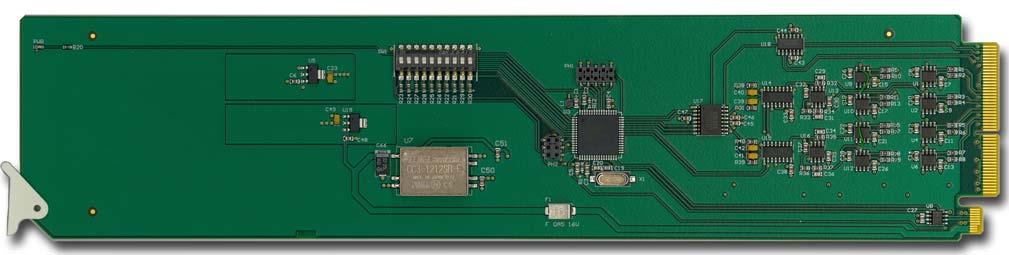
22 Card Overview This section provides a general overview of the ADA-8405-C DIP Switches. Refer to Figure 3.1 for DIP Switch location. SW1 Remote Control Figure 3.1 ADA-8405-C Components Use SW1 to disable remote control of the ADA-8405-C from DashBoard. Set SW1 as follows: ON Select this setting to disable remote control from DashBoard. The parameters and settings cannot be changed via DashBoard and must be changed using the card-edge controls. You can still monitor the status of the card using DashBoard. OFF Select this setting to control the ADA-8405-C exclusively from DashBoard. The card-edge controls are ignored. This is the default setting. SW2 DIP Switch Control Use SW2 to determine whether DIP Switch settings are applied or ignored. Set SW2 as follows: ON DIP Switch status is reported in DashBoard, and DIP Switch settings are applied. Any parameter adjustments made in DashBoard are ignored. OFF DIP Switch status is reported in DashBoard, however DIP Switch settings are ignored. Parameter adjustments made in DashBoard are applied. This is the default setting. SW3, SW4 Output Mode Selection SW3 and SW4 are used in conjunction to set the output mode of the ADA-8405-C. Refer to the section Setting the Output Mode on page 3-3 for details. SW5 This DIP Switch is not implemented. SW6 - SW10 Gain Control These switches are used in conjunction to apply a specific Gain value (db). Refer to the section Specifying the Gain on page 3-3 for details. 3 2 User Controls ADA-8405-C User Manual (Iss. 01)
23 Configuring the DIP Switches This section provides a brief summary of the DIP Switches of the ADA-8405-C. Refer to Figure 3.1 for the DIP Switch locations. Figure 3.2 shows all the DIP Switches in the OFF position. O N Figure 3.2 DIP Switches OFF Positions Enabling Card-edge Control Ensure that SW1 is set to ON and SW2 is set to ON if you are going to use the card-edge DIP Switches to change settings on the card. You can still monitor the card status in DashBoard. Setting the Output Mode SW3 and SW4 are used in conjunction to set the output mode of the ADA-8405-C. Table 3.1 lists the combinations of DIP Switch settings for SW3 and SW4. 10 Table 3.1 Setting the Output Mode SW3 SW4 Mode Selected OFF OFF Stereo DA (1x4) OFF ON Mono DA (1x8) ON ON Stereo Sum Specifying the Gain SW6-SW10 are used in conjunction to specify the coarse level gain adjustment applied to the output of the ADA-8405-C. Table 3.2 lists the combinations of DIP Switch settings for SW6-SW10. Table 3.2 Specifying the Gain SW6 SW7 SW8 SW9 SW10 Gain (db) OFF OFF OFF OFF OFF UNITY OFF OFF OFF OFF ON 1 OFF OFF OFF ON OFF 2 OFF OFF OFF ON ON 3 OFF OFF ON OFF OFF 4 OFF OFF ON OFF ON 5 OFF OFF ON ON OFF 6 OFF OFF ON ON ON 7 OFF ON OFF OFF OFF 8 OFF ON OFF OFF ON 9 OFF ON OFF ON OFF 10 ADA-8405-C User Manual (Iss. 01) User Controls 3 3
24 Table 3.2 Specifying the Gain SW6 SW7 SW8 SW9 SW10 Gain (db) OFF ON OFF ON ON 11 OFF ON ON OFF OFF 12 OFF ON ON OFF ON 13 OFF ON ON ON OFF 14 OFF ON ON ON ON 15 ON OFF OFF OFF OFF UNITY ON OFF OFF OFF ON -1 ON OFF OFF ON OFF -2 ON OFF OFF ON ON -3 ON OFF ON OFF OFF -4 ON OFF ON OFF ON -5 ON OFF ON ON OFF -6 ON OFF ON ON ON -7 ON ON OFF OFF OFF -8 ON ON OFF OFF ON -9 ON ON OFF ON OFF -10 ON ON OFF ON ON -11 ON ON ON OFF OFF -12 ON ON ON OFF ON -13 ON ON ON ON OFF -14 ON ON ON ON ON User Controls ADA-8405-C User Manual (Iss. 01)
25 Control and Monitoring Features This section provides information on the card-edge LEDs for the ADA-8405-C. Refer to Figure 3.3 for the location of the LEDs. PWR LED Card Ejector Figure 3.3 ADA-8405-C Card-edge LEDs Status and Selection LEDs on the ADA-8405-C Basic LED displays and descriptions are provided in Table 3.3. Table 3.3 LEDs on the ADA-8405-C LED Color Display and Description PWR Green When lit, this LED indicates the card is powered on. ADA-8405-C User Manual (Iss. 01) User Controls 3 5
26 3 6 User Controls ADA-8405-C User Manual (Iss. 01)
27 DashBoard Menus In This Chapter This chapter briefly summarize the menus, items, and parameters available from the DashBoard Control System for the ADA-8405-C. Parameters marked with an asterisk (*) are the factory default values. The following topic is discussed: Status Tabs Settings Tab ADA-8405-C User Manual (Iss. 01) DashBoard Menus 4 1
28 Status Tabs This section summarizes the read-only information displayed in the Status tabs. Product Tab Table 4.1 summarizes the read-only information displayed in the Product tab. Table 4.1 Product Tab Items Tab Title Item Parameters Description Card Info (Read-only) Card Name Analog Audio and Timecode Distribution Amplifier Product ADA-8405-C Supplier Ross Video Ltd. Serial Number # Indicates the serial number of the board Software Rev #.## Indicates the software version 4 2 DashBoard Menus ADA-8405-C User Manual (Iss. 01)
29 Settings Tab Table 4.2 summarizes the Settings options available in DashBoard. Table 4.2 Settings Menu Items Tab Title Item Parameters Description Settings Mode Stereo DA (2x4) Mono DA (1x8) ANLG In 1 outputs to ANLG Out 1-1, 1-2, 1-3, and 1-4 ANLG In 2 outputs to ANLG Out 2-1, 2-2, 2-3, and 2-4 ANLG In 1 outputs to all eight ANLG outputs Stereo Sum Card outputs a sum of ANLG In 1 and 2 to all eight ANLG outputs STEREO Gain Control 0 to 100 Adjusts the audio gain for all outputs Left Trim Control (db) -15 to +15 Right Trim Control (db) -15 to +15 Specifies the coarse level gain adjustment applied to ANLG In 1 Specifies the coarse level gain adjustment applied to ANLG In 2 ADA-8405-C User Manual (Iss. 01) DashBoard Menus 4 3
30 4 4 DashBoard Menus ADA-8405-C User Manual (Iss. 01)
31 Specifications In This Chapter This chapter provides the technical specification information for the ADA-8405-C. Note that specifications are subject to change without notice. The following topics are discussed: Technical Specifications ADA-8405-C User Manual (Iss. 01) Specifications 5 1
32 Technical Specifications This section provides the technical specifications for the ADA-8405-C. Table 5.1 ADA-8405-C Technical Specifications Category Parameter Specification Number of Inputs 8310AR-042 and 8320AR-042: AR-043: 1 Analog Inputs Input Impedance >20Kohm, balanced Connector WECO Maximum Input Level +27.5dBu Gain -15dB to +15dB Frequency Response ±0.1dB from 20Hz to 20kHz Performance Noise <-85dBu, 10-22kHz at unity gain Harmonic Distortion <0.01% Maximum Output Level +27dBu Analog Outputs Impedance 60ohm balanced Isolation >60dB Power Maximum Power Consumption >4.5W 5 2 Specifications ADA-8405-C User Manual (Iss. 01)
33 Service Information In This Chapter This chapter contains the following sections: Troubleshooting Checklist Warranty and Repair Policy ADA-8405-C User Manual (Iss. 01) Service Information 6 1
34 Troubleshooting Checklist Routine maintenance to this opengear product is not required. In the event of problems with your ADA-8405-C, the following basic troubleshooting checklist may help identify the source of the problem. If the frame still does not appear to be working properly after checking all possible causes, please contact your opengear products distributor, or the Technical Support department at the numbers listed under the Contact Us section. 1. Visual Review Performing a quick visual check may reveal many problems, such as connectors not properly seated or loose cables. Check the card, the frame, and any associated peripheral equipment for signs of trouble. 2. Power Check Check the power indicator LED on the distribution frame front panel for the presence of power. If the power LED is not illuminated, verify that the power cable is connected to a power source and that power is available at the power main. Confirm that the power supplies are fully seated in their slots. If the power LED is still not illuminated, replace the power supply with one that is verified to work. 3. Re-seat the Card in the Frame Eject the card and reinsert it in the frame. 4. Check Control Settings Refer to the Installation and Operation sections of the manual and verify all user-adjustable component settings. 5. Input Signal Status Verify that source equipment is operating correctly and that a valid signal is being supplied. 6. Output Signal Path Verify that destination equipment is operating correctly and receiving a valid signal. 7. Card Exchange Exchanging a suspect card with a card that is known to be working correctly is an efficient method for localizing problems to individual cards. 6 2 Service Information ADA-8405-C User Manual (Iss. 01)
35 Warranty and Repair Policy The ADA-8405-C is warranted to be free of any defect with respect to performance, quality, reliability, and workmanship for a period of FIVE (5) years from the date of shipment from our factory. In the event that your ADA-8405-C proves to be defective in any way during this warranty period, Ross Video Limited reserves the right to repair or replace this piece of equipment with a unit of equal or superior performance characteristics. Should you find that this ADA-8405-C has failed after your warranty period has expired, we will repair your defective product should suitable replacement components be available. You, the owner, will bear any labor and/or part costs incurred in the repair or refurbishment of said equipment beyond the FIVE (5) year warranty period. In no event shall Ross Video Limited be liable for direct, indirect, special, incidental, or consequential damages (including loss of profits) incurred by the use of this product. Implied warranties are expressly limited to the duration of this warranty. This ADA-8405-C User Manual provides all pertinent information for the safe installation and operation of your opengear Product. Ross Video policy dictates that all repairs to the ADA-8405-C are to be conducted only by an authorized Ross Video Limited factory representative. Therefore, any unauthorized attempt to repair this product, by anyone other than an authorized Ross Video Limited factory representative, will automatically void the warranty. Please contact Ross Video Technical Support for more information. In Case of Problems Should any problem arise with your ADA-8405-C, please contact the Ross Video Technical Support Department. (Contact information is supplied at the end of this publication.) A Return Material Authorization number (RMA) will be issued to you, as well as specific shipping instructions, should you wish our factory to repair your ADA-8405-C. If required, a temporary replacement frame will be made available at a nominal charge. Any shipping costs incurred will be the responsibility of you, the customer. All products shipped to you from Ross Video Limited will be shipped collect. The Ross Video Technical Support Department will continue to provide advice on any product manufactured by Ross Video Limited, beyond the warranty period without charge, for the life of the equipment. ADA-8405-C User Manual (Iss. 01) Service Information 6 3
36 Contact Us Contact our friendly and professional support representatives for the following: Name and address of your local dealer Product information and pricing Technical support Upcoming trade show information Technical Support Telephone: After Hours Emergency: General Information Telephone: Fax: Website: Visit Us Visit our website for: Company information and news Related products and full product lines Online catalog Testimonials
Ross Video Limited SEA-8203A. MD-SDI Equalizing Amplifier. User Manual. Ross Part Number: 8203ADR-004 Issue: 01
 Ross Video Limited SEA-8203A MD-SDI Equalizing Amplifier User Manual Ross Part Number: 8203ADR-004 Issue: 01 SEA-8203A MD-SDI Equalizing Amplifier User Manual Ross Part Number: 8203ADR-004 Document Issue:
Ross Video Limited. DSS-8224 Dual MD-SDI Switch User Manual
 Ross Video Limited DSS-8224 Dual MD-SDI Switch User Manual DSS-8224 Dual MD-SDI Switch User Manual Ross Part Number: 8224DR-004-04 Release Date: November 26, 2010. Printed in Canada. The information contained
ADA-9501 AES/EBU Reclocking Amplifier
 Ross Video Limited ADA-9501 AES/EBU Reclocking Amplifier User Manual Ross Part Number: 9501DR-004 Issue: 01E ADA-9501 AES/EBU Reclocking Amplifier User Manual Ross Part Number: 9501DR-004 Document Issue:
8024-DSS-02 Issue 2. DSS-8024 Dual Serial Switch USER MANUAL
 8024-DSS-02 Issue 2 DSS-8024 Dual Serial Switch USER MANUAL DSS-8024 Dual Serial Switch User Manual Ross Part Number: 8024-DSS-02 Document Issue: 2 Printing Date: March 15, 2000. Printed in Canada. The
VRC-100. VANC Receiver User Manual
 VRC-100 VANC Receiver User Manual VRC-100 User Manual Ross Part Number: VRC100DR-004-03 Release Date: April 30, 2012. The information in this manual is subject to change without notice or obligation. Copyright
Ross Video Limited CEG-100. CDP Error Generator. User Manual. Product Name: CEG-100
 Ross Video Limited CEG-100 CDP Error Generator User Manual Product Name: CEG-100 CEG-100 CDP Error Generator User Manual Ross Part Number: CEG100DR-004-02 Release Date: September 21, 2010. Printed in Canada.
Ross Video Limited. MDK-111A-M and MDK-111A-K. Multi-Definition Digital Keyers Owner s Manual
 Ross Video Limited MDK-111A-M and MDK-111A-K Multi-Definition Digital Keyers Owner s Manual MDK-111A-M and MDK-111A-K Multi-Definition Digital Keyers Owner s Manual Ross Part Number: 111AMDR-004-03 Release
X-Series Expansion Cards. X-Video Card
 X-Series Expansion Cards X-Video Card User s Guide v1.0 - February 2006 Warnings FCC warning This equipment has been tested and found to comply with the limits for a Class A digital device, pursuant to
ROSS VIDEO LIMITED PAA Programmable Audio Amplifier USER MANUAL PAA-01-MNL Issue 1
 ROSS VIDEO LIMITED PAA-7803 Programmable Audio Amplifier USER MANUAL 7803-PAA-01-MNL Issue 1 PAA-7803 Programmable Audio Amplifier User s Manual Ross Part Number: 7803-PAA-01-MNL Document Issue: 1 Printing
Ross Video Limited DAC-9213-PVM Multi-Definition SDI to Analog Component Converter for Sony Monitors User Manual
 Ross Video Limited DAC-9213-PVM Multi-Definition SDI to Analog Component Converter for Sony Monitors User Manual Ross Part Number: 9213PVMD-004 Issue: 02B DAC-9213-PVM Multi-Definition SDI to Analog Component
Ross Video Limited. MDK-111A-Lite. Multi-Definition Digital Keyer Owner s Manual
 Ross Video Limited MDK-111A-Lite Multi-Definition Digital Keyer Owner s Manual MDK-111A-Lite Multi-Definition Digital Keyer Owner s Manual Ross Part Number: 111MLDR-004-04 Release Date: April 13, 2011.
8020A-D-DVB-03-MNL Issue 3. DVB-8020A-D Digital Video Buffer Delay Version USER MANUAL
 8020A-D-DVB-03-MNL Issue 3 DVB-8020A-D Digital Video Buffer Delay Version USER MANUAL DVB-8020A-D Digital Video Buffer Delay Version User Manual Ross Part Number: 8020A-D-DVB-03-MNL Document Issue: 3 Printing
Kramer Electronics, Ltd. USER MANUAL. Model: VM-3A. Audio Distributor
 Kramer Electronics, Ltd. USER MANUAL Model: VM-3A Audio Distributor Contents Contents 1 Introduction 1 2 Getting Started 1 2.1 Quick Start 2 3 Overview 3 4 Your Audio Distributor 4 5 Connecting Your Audio
CardModule. Reference Manual. Series C DA Channel SDI to CVBS Converter. Version 1.0
 Reference Manual C DA 5005 5 Channel SDI to CVBS Converter Version 1.0 Series 5000 CardModule LYNX Technik AG Brunnenweg 3 D-64331 Weiterstadt Germany www.lynx-technik.com Information in this document
User Instructions. 16 SCB Sync Station.
 User Instructions 16 SCB Sync Station Contents Overview... 1 Specifications... 1 Compliance and approvals... 2 Safety instructions... 3 Set up... 4 How to charge multiple devices... 4 How to synchronize
Ross Video Limited USO RESTRITO. VANC Monitor User Manual
 Ross Video Limited VANC Monitor User Manual VANC Monitor User Manual Ross Part Number: WHZ890DR-004-02 Release Date: October 1, 2010. Printed in Canada. The information contained in this manual is subject
FIBER FIRST. opengear OG3600 Series. Fiber Transport Cards User Manual. Fiber Optic Solutions. Creating Broadcast & Cinema Equipment since 1977
 opengear OG3600 Series Transport Cards User Manual Optic Solutions 10 Newton Place Hauppauge, NY 11788 (800)-488-8378 / (516)-671-7278 sales@multidyne.com www.multidyne.com FIBER FIRST Creating Broadcast
Kramer Electronics, Ltd. USER MANUAL. Model: 810B. Black Burst / Audio Generator
 Kramer Electronics, Ltd. USER MANUAL Model: 810B Black Burst / Audio Generator Contents Contents 1 Introduction 1 2 Getting Started 1 3 Your 810B Black Burst / Audio Generator 1 4 Connecting the 810B Black
Kramer Electronics, Ltd. USER MANUAL. Models: OC-1N, Video Isolator OC-2, Dual Channel Video Isolator OC-4, Quad Channel Video Isolator
 Kramer Electronics, Ltd. USER MANUAL Models: OC-1N, Video Isolator OC-2, Dual Channel Video Isolator OC-4, Quad Channel Video Isolator Contents Contents 1 Introduction 1 2 Getting Started 1 2.1 Quick Start
Kramer Electronics, Ltd.
 Kramer Electronics, Ltd. Preliminary USER MANUAL Model: VM-1110xl Balanced Audio Distributor Contents Contents 1 Introduction 1 2 Getting Started 1 2.1 Quick Start 2 3 Overview 3 4 Your VM-1110xl Balanced
Kramer Electronics, Ltd. USER MANUAL. Model: VM Video Component Distributor
 Kramer Electronics, Ltd. USER MANUAL Model: VM-1045 Video Component Distributor Contents Contents 1 Introduction 1 2 Getting Started 1 2.1 Quick Start 1 3 Overview 3 4 Your VM-1045 Video Component Distributor
AES-402 Automatic Digital Audio Switcher/DA/Digital to Analog Converter
 Broadcast Devices, Inc. AES-402 Automatic Digital Audio Switcher/DA/Digital to Analog Converter Technical Reference Manual Broadcast Devices, Inc. Tel. (914) 737-5032 Fax. (914) 736-6916 World Wide Web:
SoundPals. ADC-24 User Guide. Stereo A-to-D Converter
 SoundPals Stereo A-to-D Converter Printing History SoundPals ADC-24 A-to-D converter Rev. N/C SEPTEMBER 2016 Printed in U.S.A. Part Number 08-2045-00 The information contained in this guide is subject
Kramer Electronics, Ltd. USER MANUAL. Model: VM-10xl. Video Audio Distribution Amplifier
 Kramer Electronics, Ltd. USER MANUAL Model: VM-10xl Video Audio Distribution Amplifier Contents Contents 1 Introduction 1 2 Getting Started 1 2.1 Quick Start 1 3 Overview 3 4 Your VM-10xl Video Audio Distribution
AES-404 Digital Audio Switcher/DA/Digital to Analog Converter
 Broadcast Devices, Inc. AES-404 Digital Audio Switcher/DA/Digital to Analog Converter Technical Reference Manual Broadcast Devices, Inc. Tel. (914) 737-5032 Fax. (914) 736-6916 World Wide Web: www.broadcast-devices.com
OPERATOR MANUAL OSD8865 DIGITAL TRIPLE VIDEO FIBER OPTIC RECEIVER
 OPERATOR MANUAL OSD8865 DIGITAL TRIPLE VIDEO FIBER OPTIC RECEIVER INDEX 1 1 TECHNICAL SUMMARY... 4 1.1 BRIEF DESCRIPTION... 4 1.1.1 OVERVIEW... 4 1.1.2 APPLICATIONS... 4 1.1.3 FEATURES AND BENEFITS...
Operating Instructions
 Operating Instructions SDI Input board Model No. AV-HS04M1 РУССКИЙ FRANÇAIS DEUTSCH ENGLISH ESPAÑOL ITALIANO Before operating this product, please read the instructions carefully and save this manual for
Instant 802.3af Gigabit Outdoor PoE Converter. Model: INS-3AF-O-G. Quick Start Guide
 Instant 802.3af Gigabit Outdoor PoE Converter Model: INS-3AF-O-G Quick Start Guide QUICK START GUIDE Introduction Thank you for purchasing the Ubiquiti Networks Instant 802.3af Gigabit Outdoor PoE Converter.
User Guide. Centrex Recording Interface
 User Guide Centrex Recording Interface Table of Contents Introduction... 2 The Meridian Business Set... 3 Key Numbering Plan (18 button add-on)... 4 Key Numbering Plan (36 button add-on)... 5 Key Numbering
AES Channel Digital/Analog Audio Switcher/DA/Digital to Analog Converter
 Broadcast Devices, Inc. AES-408 8 Channel Digital/Analog Audio Switcher/DA/Digital to Analog Converter Technical Reference Manual Broadcast Devices, Inc. Tel. (914) 737-5032 Fax. (914) 736-6916 World Wide
User Manual TL-2X1-HDVC 2x1 HDMI & VGA Switcher with Control All Rights Reserved Version: TL-2X1-HDVC_160630
 User Manual TL-2X1-HDVC 2x1 HDMI & VGA Switcher with Control All Rights Reserved Version: TL-2X1-HDVC_160630 Preface Read this user manual carefully before using this product. Pictures shown in this manual
USER MANUAL. Kramer Electronics, Ltd. Models:
 Kramer Electronics, Ltd. USER MANUAL Models: 103AV, 1:3 Audio-Stereo / Video DA 104M, 1:4 Microphone Amplifier 105A, 1:5 Stereo Audio DA 105S, 1:5 High Resolution s-video DA 105V, 1:5 High Resolution Video
MultiView T4 / T5 Transmitter
 MultiView T4 / T5 Transmitter Quick Reference & Setup Guide Magenta Research 128 Litchfield Road, New Milford, CT 06776 USA (860) 210-0546 FAX (860) 210-1758 www.magenta-research.com PN 5310188-01, Rev
Model 570 Fiber Optic
 Model 570 Fiber Optic Transmit Trigger Package The World Leader in Subsurface Imaging December, 2005 Geophysical Survey Systems, Inc. Tel 603.893.1109 Fax 603.889.3984 sales@geophysical.com www.geophysical.com
RD10MD Dual HD to SD Down Converter R-series Card Module
 RD0MD Dual HD to SD Down Converter R-series Card Module User Manual March 30, 2006 P/N 0665-00 2 Trademarks AJA, Io, and Kona are trademarks of AJA Video, Inc. All other trademarks are the property of
Kramer Electronics, Ltd. USER MANUAL. Models: PT-102AN, 1:2 Audio DA PT-102SN, 1:2 s-video DA
 Kramer Electronics, Ltd. USER MANUAL Models: PT-102AN, 1:2 Audio DA PT-102SN, 1:2 s-video DA Contents Contents 1 Introduction 1 2 Getting Started 1 2.1 Quick Start 1 3 Overview 3 3.1 About the PT102AN
Reference Manual D VD 5820
 Reference Manual D VD 5820 3GBit/s Dual SDI/ASI Distribution Amplifier Revision 1.0 May 2010 This Manual Supports Device Revisions: D VD 5820 Firmware Revision 377 Control System GUI Release 4.7.3 Information
AITech ProA/V Media Extender 5GHz Digital
 AITech ProA/V Media Extender 5GHz Digital 5 GHz Wireless Digital Media Transmitter and Receiver User Manual Table of Contents 1. Package Contents 2. Panels and Functions AV Sender AV Receiver 3. Setup
User Manual TL-2X1-HDV 2x1 HDMI & VGA Switcher All Rights Reserved Version: TL-2X1-HDV_160630
 User Manual TL-2X1-HDV 2x1 HDMI & VGA Switcher All Rights Reserved Version: TL-2X1-HDV_160630 Preface Read this user manual carefully before using this product. Pictures shown in this manual are for reference
Kramer Electronics, Ltd. USER MANUAL. Model: PT-102VN. 1:2 Video DA
 Kramer Electronics, Ltd. USER MANUAL Model: PT-102VN 1:2 Video DA Contents Contents 1 Introduction 1 2 Getting Started 1 2.1 Quick Start 2 3 Overview 3 4 Your PT-102VN 1:2 Video DA 4 5 Using the PT-102VN
DA8-T DA8-T MANUAL
 J C F A U D I O MANUAL 1.0 contact@jcfaudio.com www.jcfaudio.com Safety Information Do not repair, modify, service this device except in the manner in which it is described in this manual. Doing so can
Passive Four Channel Stereo/Mono Mixer/Splitter. Artcessories. User's Manual
 Passive Four Channel Stereo/Mono Mixer/Splitter Artcessories User's Manual IMPORTANT SAFETY INSTRUCTION READ FIRST This symbol, whenever it appears, alerts you to the presence of uninsulated dangerous
Kramer Electronics, Ltd. USER MANUAL. Model: VS x1 Video Audio Switcher
 Kramer Electronics, Ltd. USER MANUAL Model: VS-421 4x1 Video Audio Switcher Contents Contents 1 Introduction 1 2 Getting Started 1 3 Overview 1 4 Your Video Audio Matrix Switcher 2 5 Connecting the Video
Kramer Electronics, Ltd. USER MANUAL. Model: 482xl. Bi-directional Audio Transcoder
 Kramer Electronics, Ltd. USER MANUAL Model: 482xl Bi-directional Audio Transcoder Contents Contents 1 Introduction 1 2 Getting Started 1 3 Overview 2 4 Your Bi-directional Audio Transcoder 2 5 Connecting
SC-C1M SiriusConnect TM Vehicle Tuner
 SC-C1M SiriusConnect TM Vehicle Tuner For Special Market Applications Installation Guide Congratulations on the Purchase of your new SIRIUS SC-C1 SiriusConnect TM Vehicle Tuner. The SC-C1M is packaged
 Register your product and get support at www.philips.com/welcome SWS3435S/27 SWS3435H/37 EN User manual Contents 1 Important 4 Safety 4 English 2 Your SWS3435 6 Overview 6 3 Installation 7 Connect the
MWT-FM. Operation Manual. FM Single Channel Transmitter. man_mwtfm.
 MWT-FM FM Single Channel Transmitter Operation Manual man_mwtfm www.myeclubtv.com CONTENTS FCC COMPLIANCE STATEMENT. 3 INDUSTRY CANADA COMPLIANCE 3 MWT-FM ORIENTATION. 4 SAFETY PRECAUTIONS 5 FINDING FM
Kramer Electronics, Ltd. USER MANUAL. Model: Power Amplifier
 Kramer Electronics, Ltd. USER MANUAL Model: 900 Power Amplifier Contents Contents 1 Introduction 1 2 Getting Started 1 3 Overview 1 4 Your 900 Power Amplifier 2 5 Connecting your 900 Power Amplifier 4
VGA Extender over Single CAT 6 Cable with Audio Support. Model Extend both video and audio up to 1000 feet
 VGA Extender over Single CAT 6 Cable with Audio Support Model 103004 Extend both video and audio up to 1000 feet Utilize a Cat 6 cable instead of a bulky VGA cable Supports a local monitor and local speakers
Universal Wireless HDTV Adapter
 Universal Wireless HDTV Adapter F7D4555v1 User Manual Table of Contents CHAPTER 1 INTRODUCTION... 1 Package Contents... 1 Features... 1 LEDs... 2 CHAPTER 2 INITIAL INSTALLATION... 4 Requirements... 4 Procedure...
VAM6800 A/D Conversion and Audio Embedder USER MANUAL
 VAM6800 A/D Conversion and Audio Embedder USER MANUAL Product Information Model: VAM6800 A/D Conversion and Audio Embedder Version: V010002 Release Date: July 19th, 2010 Company OSEE TECHNOLOGY CO., LTD.
User Manual PS-684. HDBaseT Extender Kit 70m. All Rights Reserved. Version: UHBT70P_2016V1.2
 User Manual PS-684 All Rights Reserved Version: UHBT70P_2016V1.2 Preface Read this user manual carefully before using this product. Pictures shown in this manual is for reference only, different model
Content. User s Manual 3. Owner s Manual Ver. 1.1 / June Introduction...4. Mytek Package Content Features...
 Owner s Manual User s Manual 3 Content Owner s Manual Ver. 1.1 / June 2018 Mytek 2017 The Brooklyn AMP firmware can be easily updated via Mytek USB Control Panel. As the firmware is updated, Mytek will
English. User Manual sub8 Subwoofer SUBWOOFER. Supporting your digital lifestyle
 English User Manual sub8 Subwoofer U SUBWOOFER Supporting your digital lifestyle Table of Contents Important Safety Precautions........ 2 Introduction / What s in the Box?...... 3 Front & Rear Panels............
User Manual CVA3. HDMI Audio Decoder. All Rights Reserved. Version: CVA3_2016V1.0
 User Manual CVA3 All Rights Reserved Version: CVA3_2016V1.0 Preface Read this user manual carefully before using this product. Pictures shown in this manual is for reference only, different model and specifications
Kramer Electronics, Ltd. USER MANUAL. Model: VS-211HDxl. 3G HD-SDI Automatic Standby Switcher
 Kramer Electronics, Ltd. USER MANUAL Model: VS-211HDxl 3G HD-SDI Automatic Standby Switcher Contents Contents 1 Introduction 1 2 Getting Started 1 2.1 Quick Start 2 3 Overview 3 4 Your VS-211HDxl 3G HD-SDI
Instructions. P MHz 1X/10X Passive Probe
 Instructions P2100 100 MHz 1X/10X Passive Probe 071-0774-01 071077401 Copyright Tektronix, Inc. All rights reserved. Tektronix products are covered by U.S. and foreign patents, issued and pending. Information
WXL-2F, WXL-1F, WXL-2M, WXL-1M
 Kramer Electronics, Ltd. USER MANUAL Wall Plate (WXL) Series Multifunctional Passive Wall Plates: WXL-1FM, WXL-2F, WXL-1F, WXL-2M, WXL-1M Contents Contents 1 Introduction 1 2 Getting Started 1 3 Overview
SK2002DA SIDEKICKER 1-IN, 2-OUT VGA-UXGA DISTRIBUTION AMPLIFIER CABLE USER S GUIDE DISTRIBUTION AMPLIFIERS
 MANUAL PART NUMBER: 400-0152-001 PRODUCT REVISION: 0 SK2002DA SIDEKICKER 1-IN, 2-OUT VGA-UXGA DISTRIBUTION AMPLIFIER CABLE USER S GUIDE TABLE OF CONTENTS Page PRECAUTIONS / SAFETY WARNINGS...2 GENERAL...2
Kramer Electronics, Ltd. USER MANUAL. Model: VS-33Vxl. 3x1 Video Switcher
 Kramer Electronics, Ltd. USER MANUAL Model: VS-33Vxl 3x1 Video Switcher Contents Contents 1 Introduction 1 2 Getting Started 1 2.1 Quick Start 1 3 Overview 3 3.1 Recommendations for Achieving the Best
DVI Rover 700 User Guide
 DVI Rover 700 User Guide Featuring ExtremeDVI Technology DVI Rover 700 This document applies to Part Numbers: 00-00106 through 00-00141 inclusive. FCC Radio Frequency Interference Statement Warning The
USER INSTRUCTIONS MODEL CSI-200 COAXIAL SYSTEM INTERFACE
 USER INSTRUCTIONS MODEL CSI-200 COAXIAL SYSTEM INTERFACE 9350-7676-000 Rev B, 5/2001 PROPRIETARY NOTICE The RTS product information and design disclosed herein were originated by and are the property of
Model Extend HDMI audio and video connections up to 300 feet. Add up to 8 additional receivers with a dedicated network switch
 HDMI Extender over Single CAT 6 Cable with IR Control Model 103002 Extend HDMI audio and video connections up to 300 feet Utilize existing Cat 6 wiring for an easy installation Add up to 8 additional receivers
Kramer Electronics, Ltd. USER MANUAL. Model: VA-100P-5. Power Supply
 Kramer Electronics, Ltd. USER MANUAL Model: VA-100P-5 Power Supply Contents Contents 1 Introduction 1 2 Getting Started 1 2.1 Quick Start 1 3 Overview 2 4 Your Power Supply 3 5 Using the Power Supply 4
Introduction. Package Contents. Installation Requirements
 Security Camera Security Camera Introduction Introduction Thank you for purchasing the aircam Dome. This Quick Start Guide is designed to guide you through the installation of the aircam Dome and show
Long Range Ethernet Extender
 CopperLink Model 2160 Series Long Range Ethernet Extender Quick Start Guide Part Number: 07M2160-QS, Rev. B Revised: February 24, 2012 Sales Office: +1 (301) 975-1000 Technical Support: +1 (301) 975-1007
Kramer Electronics, Ltd. USER MANUAL. Models: TR-1YC, s-video Isolation Transformer TR-2YC, s-video Dual Isolation Transformers
 Kramer Electronics, Ltd. USER MANUAL Models: TR-1YC, s-video Isolation Transformer TR-2YC, s-video Dual Isolation Transformers Contents Contents 1 Introduction 1 2 Getting Started 1 2.1 Quick Start 1 3
Kramer Electronics, Ltd.
 Kramer Electronics, Ltd. Preliminary USER MANUAL Model: FC-332 SD/HD-SDI to HDMI Converter/DA Contents Contents 1 Introduction 1 2 Getting Started 1 2.1 Quick Start 1 3 Overview 2 3.1 About HDMI 3 3.2
SignalOn Series. L-Band Splitter Module INSTALLATION & OPERATION MANUAL. 1.2 GHz. D3.
 SignalOn Series D3.1/CCAP Compliant 1.2 GHz L-Band Splitter Module INSTALLATION & OPERATION MANUAL www.atxnetworks.com www.atxnetworks.com Although every effort has been taken to ensure the accuracy of
User Guide. HDMI Fiber Optic Extender. DVI-7350a
 User Guide HDMI Fiber Optic Extender DVI-7350a Table of Contents Section Page Product Safety.................................... 1 1.0 Introduction...2 2.0 Specifications...3 3.0 Package Contents...3 4.0
Kramer Electronics, Ltd. USER MANUAL. Model: PT-101Hxl. HDMI Repeater
 Kramer Electronics, Ltd. USER MANUAL Model: PT-101Hxl HDMI Repeater Contents Contents 1 Introduction 1 2 Getting Started 1 2.1 Quick Start 2 3 Overview 3 3.1 About HDMI 3 3.2 About HDCP 4 4 Your PT-101Hxl
Kramer Electronics, Ltd.
 Kramer Electronics, Ltd. Preliminary USER MANUAL Model: 6808HDxl HD/SD-SDI AES De-Embedder Contents Contents 1 Introduction 1 2 Getting Started 1 2.1 Quick Start 2 3 Overview 3 4 Your 6808HDxl HD/SD-SDI
Kramer Electronics, Ltd. USER MANUAL. Model: VM-2DVI. High Resolution / Dual Link 1:2 DVI Distributor
 Kramer Electronics, Ltd. USER MANUAL Model: VM-2DVI High Resolution / Dual Link 1:2 DVI Distributor Contents Contents 1 Introduction 1 2 Getting Started 1 2.1 Quick Start 1 3 Overview 3 4 Your VM-2DVI
Kramer Electronics, Ltd. USER MANUAL. Models: 6410N, Digital to Analog Audio Converter 6420N, Analog to Digital Audio Converter
 Kramer Electronics, Ltd. USER MANUAL Models: 6410N, Digital to Analog Audio Converter 6420N, Analog to Digital Audio Converter Contents Contents 1 Introduction 1 2 Getting Started 1 2.1 Quick Start 1 3
Register your product and get support at SDV5122/27. EN User manual
 Register your product and get support at www.philips.com/welcome SDV5122/27 User manual Contents 1 Important 4 Safety 4 Notice for USA 5 Notice for Canada 5 Recycling 6 English 2 Your SDV5122 7 Overview
Backlight Replacement
 Installation Instructions Backlight Replacement Catalog Numbers 2711P-RL7C, 2711P-RL7C2, 2711P-RL10C, 2711P-RL10C2, 2711P-RL12C, 2711P-RL12C2, 2711P-RL15C Topic Page About This Publication 1 Important
User Manual TL-TP70-HDIR 70m Extender with ARC and IR All Rights Reserved Version: TL-TP70-HDIR_180723
 User Manual TL-TP70-HDIR 70m Extender with ARC and IR All Rights Reserved Version: TL-TP70-HDIR_180723 Preface Read this user manual carefully before using this product. Pictures shown in this manual is
Kramer Electronics, Ltd.
 Kramer Electronics, Ltd. Preliminary USER MANUAL Model: FC-322 SD/HD-SDI to HDMI Converter/Switcher/DA Contents Contents 1 Introduction 1 2 Getting Started 1 2.1 Quick Start 2 3 Overview 2 3.1 About HDMI
USER MANUAL. Kramer Electronics, Ltd. Models:
 Kramer Electronics, Ltd. USER MANUAL Models: 707, Video Audio Line Transmitter 708, Video Audio Line Receiver 709, Y/C Line Transmitter 710, Y/C Line Receiver 711xl, Video-Audio Line Transmitter 712xl,
Kramer Electronics, Ltd. USER MANUAL. Model: VP-200N5. 1:2 High Resolution UXGA DA
 Kramer Electronics, Ltd. USER MANUAL Model: VP-200N5 1:2 High Resolution UXGA DA Contents Contents 1 Introduction 1 2 Getting Started 1 2.1 Quick Start 2 3 Overview 2 4 Your VP-200N5 1:2 High Resolution
Kramer Electronics, Ltd.
 Kramer Electronics, Ltd. Preliminary USER MANUAL Models: VS-44AV, 4x4 Video Audio Matrix Switcher VS-81AV, 8x1 Video/Audio-Stereo Switcher VS-81AYC, 8x1 s-video/audio-stereo Switcher VS-81V, 8x1 Video
Access Converter/ 3. Operation Manual. International Headquarters. European Headquarters. B&B Electronics. 707 Dayton Road Ottawa, IL USA
 Access Converter/ 3 International Headquarters B&B Electronics Operation Manual 707 Dayton Road Ottawa, IL 61350 USA Phone (815) 433-5100 General Fax (815) 433-5105 Email: support@bb-elec.com Website:
User Manual. Model 1372A and 1374A HDMI Switchers. 1T-SX-632 Model 1372A 2X1 Switcher. v1.3 2x1 SWITCHER. v1.3 INPUT ENHANCE POWER
 User Manual 1T-SX-632 Model 1372A 2X1 Switcher v1.3 v1.3 2x1 SWITCHER 1 2 INPUT ENHANCE POWER 1 2 INPUT ENHANCE POWER Model 1372A and 1374A HDMI Switchers Table Of Contents 1.0 Introduction.......................
Perle Fast Ethernet Fiber to Fiber Media Converter Module. Installation Guide. P/N (Rev D)
") Perle Fast Ethernet Fiber to Fiber Media Converter Module Installation Guide C-100MM-XXXXX CM-100MM-XXXXX Unmanaged Module Managed Module P/N 5500313-10 (Rev D) Overview This document contains instructions
Perle Fast Ethernet Fiber to Fiber Media Converter Module Installation Guide C-100MM-XXXXX CM-100MM-XXXXX Unmanaged Module Managed Module P/N 5500313-10 (Rev D) Overview This document contains instructions
ACCESSORIES MANUAL PART NUMBER: PRODUCT REVISION: 1 TNP100. Tilt N Plug Interconnect Box USER'S GUIDE
 MANUAL PART NUMBER: 400-0091-001 PRODUCT REVISION: 1 TNP100 Tilt N Plug Interconnect Box USER'S GUIDE INTRODUCTION Your purchase of the TNP100 Tilt N Plug Interconnect Box is greatly appreciated. We are
DA IN 1-OUT LINE DRIVER WITH EQUALIZATION + AUDIO USER S GUIDE
 MANUAL PART NUMBER: 400-0430-001 1-IN 1-OUT LINE DRIVER WITH UALIZATION + AUDIO USER S GUIDE TABLE OF CONTENTS Page PRECAUTIONS / SAFETY WARNINGS... 2 GENERAL...2 GUIDELINES FOR RACK-MOUNTING...2 INSTALLATION...2
Model 6010 Four Channel 20-Bit Audio ADC Data Pack
 Model 6010 Four Channel 20-Bit Audio ADC Data Pack Revision 3.1 SW v1.0.0 This data pack provides detailed installation, configuration and operation information for the Model 6010 Four Channel 20-bit Audio
Kramer Electronics, Ltd.
 Kramer Electronics, Ltd. Preliminary USER MANUAL Model: VP-2K 1:2 UXGA / Audio Distributor Contents Contents 1 Introduction 1 2 Getting Started 1 2.1 Quick Start 2 3 Overview 3 4 Your VP-2K 1:2 UXGA /
Kramer Electronics, Ltd. USER MANUAL. Model: 6809HD. HD/SD-SDI AES Embedder
 Kramer Electronics, Ltd. USER MANUAL Model: 6809HD HD/SD-SDI AES Embedder Contents Contents 1 Introduction 1 2 Getting Started 1 2.1 Quick Start 1 3 Overview 3 4 Your 6809HD HD/SD-SDI AES Embedder 4 5
VLHDMIEXTFIB_2017V1.0
 User Manual VLHDMIEXTFI ll Rights Reserved Version: VLHDMIEXTFI_2017V1.0 Preface Read this user manual carefully before using the product. Pictures are shown in this manual for reference only, different
AM-4 Audio Monitor. Videoquip Research Limited 595 Middlefield Road, Unit #4 Scarborough, Ontario, Canada. MIV 3S2
 AM-4 Audio Monitor Videoquip Research Limited 595 Middlefield Road, Unit #4 Scarborough, Ontario, Canada. MIV 3S2 (416) 293-1042 1-888-293-1071 www.videoquip.com AM-4 4 channel Analog, AES3 Digital, SDI
Quintet SL. Owner s Manual
 Quintet SL Owner s Manual QUINTET SL SPEAKER SYSTEM IMPORTANT SAFETY INSTRUCTIONS 1. READ these instructions. 2. KEEP these instructions. 3. HEED all warnings. 4. FOLLOW all instructions. 5. DO NOT use
Six-Channel TDM Multiplexers for 3G, HD, SDI, and ASI. Installation and Operations. Manual
 Manual DigiLink DLC156 Function modules Six-Channel TDM Multiplexers for 3G, HD, SDI, and ASI Installation and Operations Manual WWW.ARTEL.COM ii DLC156 Function Modules Installation and Operations Manual
Model /29S RF Splitter
 Instruction Manual Model 1584-29/29S RF Splitter March 2013, Rev. 0 LNB VOLTAGE A B MODEL 1584 COMBINER CROSS TECHNOLOGIES INC. GND+DC ON Data, drawings, and other material contained herein are proprietary
User Manual. Model 979T and 979R Digital Audio Converters
 User Manual Model 979T and 979R Digital Audio Converters Table Of Contents 1.0 Introduction....................... 3 2.0 Checking Package Contents............... 3 3.0 Installation........................
Kramer Electronics, Ltd. USER MANUAL. Model: FC Standards Converter / TBC
 Kramer Electronics, Ltd. USER MANUAL Model: FC-4000 Standards Converter / TBC Contents Contents 1 Introduction 1 2 Getting Started 1 3 Overview 1 4 Your Standards Converter / TBC 2 4.1 Connecting the
CDV07. Analog video distribution amplifier(s)
") CDV07 Analog video distribution amplifier(s) TECHNICAL MANUAL CDV07 Analog video distribution amplifier Lange Wagenstraat 55 NL-5126 BB Gilze The Netherlands Phone: +31 161 850 450 Fax: +31 161 850 499
CDV07 Analog video distribution amplifier(s) TECHNICAL MANUAL CDV07 Analog video distribution amplifier Lange Wagenstraat 55 NL-5126 BB Gilze The Netherlands Phone: +31 161 850 450 Fax: +31 161 850 499
HD Digital MPEG2 Encoder / QAM Modulator Get Going Guide
 series HD Digital MPEG2 Encoder / QAM Modulator Get Going Guide HDb2640 HDb2620 HDb2540 HDb2520 The HDbridge 2000 Series is a combination HD MPEG 2 Encoder and frequency-agile QAM Modulator, all in a 1RU
Kramer Electronics, Ltd. USER MANUAL. Model: VP-100. VGA/XGA to RGBHV Converter
 Kramer Electronics, Ltd. USER MANUAL Model: VP-100 VGA/XGA to RGBHV Converter Contents Contents 1 Introduction 1 2 Getting Started 1 2.1 Quick Start 1 3 Overview 3 4 Your VP-100 VGA/XGA to RGBHV Converter
ACCESSORIES MANUAL PART NUMBER: TNP500. Universal Tilt N Plug Interconnect Box USER'S GUIDE
 MANUAL PART NUMBER: 400-0091-003 TNP500 Universal Tilt N Plug Interconnect Box USER'S GUIDE INTRODUCTION Your purchase of the TNP100 Tilt N Plug Interconnect Box is greatly appreciated. We are sure you