NO RETURNED PRODUCTS WILL BE ACCEPTED AT THE FACTORY WITHOUT A RETURN AUTHORIZATION NUMBER.
|
|
|
- Lesley Shepherd
- 5 years ago
- Views:
Transcription

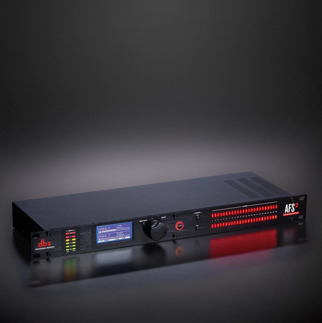
1 Owner s Manual
2 Warranty 1. The warranty registration card that accompanies this product must be mailed within 30 days after purchase date to validate this warranty. You can also register online at Proof-of-purchase is considered to be the responsibility of the consumer. A copy of the original purchase receipt must be provided for any warranty service. 2. dbx warrants this product, when purchased new from an authorized U.S. dbx dealer and used solely within the U.S., to be free from defects in materials and workmanship under normal use and service. This warranty is valid to the original purchaser only and is non-transferable. 3. dbx liability under this warranty is limited to repairing or, at our discretion, replacing defective materials that show evidence of defect, provided the product is returned to dbx WITH RETURN AUTHORIZATION from the factory, where all parts and labor will be covered up to a period of two years. A Return Authorization Number must first be obtained from dbx. The company shall not be liable for any consequential damage as a result of the product s use in any circuit or assembly. 4. dbx reserves the right to make changes in design or make additions to or improvements upon this product without incurring any obligation to install the same additions or improvements on products previously manufactured. 5. The foregoing is in lieu of all other warranties, expressed or implied, and dbx neither assumes nor authorizes any person to assume on its behalf any obligation or liability in connection with the sale of this product. In no event shall dbx or its dealers be liable for special or consequential damages or from any delay in the performance of this warranty due to causes beyond their control. Technical Support & Service If you require technical support, contact dbx Technical Support. Be prepared to accurately describe the problem. Know the serial number of your device this is printed on a sticker attached to the chassis. If you have not already taken the time to fill out your warranty registration card and send it in, please do so now. You may also register online at Before you return a product to the factory for service, we recommend you refer to this manual. Make sure you have correctly followed installation steps and operating procedures. For further technical assistance or service, please contact our Technical Support Department at (801) or visit If you need to return a product to the factory for service, you MUST first contact our Technical Support Department to obtain a Return Authorization Number. NO RETURNED PRODUCTS WILL BE ACCEPTED AT THE FACTORY WITHOUT A RETURN AUTHORIZATION NUMBER. Please refer to the Warranty information, which extends to the first end-user. After expiration of the warranty, a reasonable charge will be made for parts, labor, and packing if you choose to use the factory service facility. In all cases, you are responsible for transportation charges to the factory. If the product is still under warranty, dbx will pay the return shipping. Use the original packing material if it is available. Mark the package with the name of the shipper and with these words in red: DELICATE INSTRUMENT, FRAGILE! Insure the package properly. Ship prepaid, not collect. Do not ship parcel post.
3 Table of Contents Overview... 2 Introduction... 2 Features... 3 The AFS Advantage... 3 Installation... 4 Installation Recommendations... 4 Making Connections... 4 Applying Power... 5 The Menus & Parameters...24 AFS Options Menu...24 Preset Menu...27 System Menu...27 Technical Information...28 Audio Cable Diagrams...28 Dimensions...29 Specifications...30 Application Guide... 6 Application Overview... 6 Gain Structure... 6 Application 1 Mixer Channel Inserts... 7 Application 2 Mixer Subgroup (Bus) Inserts... 8 Application 3 Mixer Master Inserts... 9 Application 4 In-line Between Mixer & Amp...10 The User Interface & Connectors...11 Front Panel...11 Rear Panel...13 Operating The AFS Navigating & Modes Of Operation...14 Home Mode...14 Menu Mode...14 Wizard Mode...15 Menu Navigation Map...15 The AFS Filters...16 Fixed Filters...16 Live Filters...16 Filter Widths...16 Clearing Filters...17 Linking/Unlinking Channels...18 Ringing Out The Sound System...19 Using The Wizard...19 Manual Method...19 Presets...21 Saving Presets...21 Loading Presets...21 Front Panel Lockout...22 Factory Resets...23 Factory Default Reset...23 Factory Hard Reset
4 Overview Introduction The AFS2 is the second generation feedback suppression processor from dbx. Whether you re playing with your band, a live sound engineer, or an audio installer, you know how annoying and offensive feedback can be. Feedback is caused when an in-phase audio loop is created between an input transducer (such as a guitar pickup or microphone) and an output transducer (a loudspeaker). Using the updated AFS algorithm first introduced in the acclaimed dbx DriveRack PA2 speaker management system processor, the AFS2 kills feedback dead in its tracks without adversely affecting the tone of your system. The AFS2 is a two-channel device and can be configured for stereo linked or dual mono operation. It provides 24 filters per channel with filter widths as narrow as 1/80th of an octave. Filters can be configured for Live or Fixed operation. Use the Fixed filters to initially ring out the system for higher gain before feedback then use the Live filters for on-the-fly, automatic feedback protection during the performance as conditions change. 24 Filter LEDs show at-a-glance status of all filters so you re never left guessing what the processor is doing. Need more detailed information about the filters? The easy-to-read, backlit LCD display shows the frequency, width, and attenuation amount of each set filter. Not sure how to ring out a sound system? No problem. The new Wizard in the AFS2 walks you through the entire setup and ring-out procedure. Feedback suppression couldn t be any easier. Just press the big, red Wizard button and follow the on-screen instructions. The updated AFS algorithm in the AFS2 can now detect and eliminate feedback faster than ever before and with even higher precision. The AFS2 offers the following enhancements over the AFS224: It s faster at eliminating the offending feedback frequency. It can better determine what is actually feedback, making it far less likely to set false triggers on feedback-like audio sources such as a flute or keyboard. It can better determine how much attenuation is required to notch out the feedback, resulting in notch filters which aren t as deep and are even less audible. It prevents the filters from being too narrow to tackle feedback at lower frequencies. It has better frequency resolution which provides pinpoint accuracy and uses the narrowest filters possible. Live filters are lifted more gradually to better determine if it is safe to lift the filter, preventing blaring feedback from suddenly returning. Allows you to store up to 5 user presets. We think you ll agree that the AFS2 couldn t be any easier to use and is up for any feedback suppression task you throw at it. Thanks for choosing dbx. 2
5 Features Latest dbx Advanced Feedback Suppression (AFS ) Technology 24-Bit A/D, D/A Converters 48kHz/24-Bit Internal Processing 24 Programmable Filters w/status LEDs per Channel Stereo Linked or Dual Mono Operation Live & Fixed Filter Modes Selectable Live Filter Lift Times Application-Specific Filter Types Include: Speech, Music, Music/Speech 5 User Storable Presets Input Signal Level Metering w/input Clip Indicators XLR and TRS Electronically Balanced Input and Outputs +4 dbu / -10 dbv Operating Level Switch per Channel USB Port for Firmware Updates The AFS Advantage Key features that set AFS apart are the Fixed and Live Modes of operation and the Live Filter Lift feature. The Live Mode of operation continuously updates filter placement which provides flexibility during a performance. The Live Filter Lift feature automatically removes filter assignments that are no longer necessary, which in turn, maximizes sonic integrity. AFS uses precision frequency detection and state-of-the-art processing to determine the exact range of feedback frequencies to remove (instead of indiscriminately removing large sections of audio). In the past, graphic equalizers were used to eliminate feedback from a system. This was an acceptable method for eliminating feedback, but when this method is put up against precision notch filters, such as those found in AFS, it becomes very evident that using graphic equalizers for this task severely affects the tone of the system. With AFS, the precision filters remove only a fraction of the frequency spectrum, eliminating the feedback with far less audible artifacts. The below graph shows a comparison of filter widths between the AFS filters, conventional 1/3 octave EQ filters, and notch filters used in competitor s feedback elimination processors. Filter Precision Comparison Chart 3
6 Installation Installation Recommendations FOR RACK MOUNT USE ONLY. Install the AFS2 in a standard-width rack with the provided rack screws. The AFS2 should not be mounted above or below anything that generates excessive heat. Ambient temperatures should not exceed 95ºF (35ºC) when equipment is in use. Although the unit is shielded against radio frequency and electromagnetic interference, extremely high fields of RF and EMI should be avoided where possible. Making Connections The AFS2 has balanced inputs and outputs that can be connected to any balanced or unbalanced line-level device. To connect the AFS2 to your sound system: 1. Ensure the power is turned off on all interconnecting equipment and the AFS2 before making audio connections. 2. See Application Guide on page 6 for application system diagrams and notes which can be used for reference when connecting the AFS2 to your system. 3. Make audio connections via the XLR or 1/4" TRS connectors according to application needs (see Audio Cable Diagrams on page 28 for information on cable wiring). Either the XLR or 1/4" input and output connectors can be used for balanced or unbalanced connections. However, making simultaneous connections to both inputs of a channel could unbalance balanced lines, cause phase cancellation, short a conductor to ground, or cause damage to other equipment connected to the AFS2, therefore, it is not recommended. Connecting to both outputs of a channel simultaneously is perfectly acceptable as long as the combined parallel load is 1.2kΩ or greater. This is typically not a problem since most modern-day audio devices have been designed with high-impedance line inputs. If desired, parallel resistance calculators can be found online and used to verify if the parallel load meets this criteria. Simply enter the input impedance for the two receiving devices into the calculator to calculate the combined parallel load. Note that connecting both XLR and 1/4 outputs of a channel to an unbalanced and balanced input simultaneously will cause the balanced line to become unbalanced. NOTE: The +4 dbu/-10 dbv switch on the back panel of the AFS2 must be set to the correct position for your application in order to avoid performance issues. +4 dbu is referred to as pro level and will be the correct setting for most applications, as most pro and semi-pro mixers will output a nominal level of around +4 dbu. -10 dbv is referred to as consumer level and will need to be used when connecting a source which has an output level approximately 12 db lower than pro level equipment. If you re unsure of the nominal operating level of your mixer s connections, take a look at the mixer s manual or contact the mixer manufacturer. 4
7 Applying Power 1. Ensure your power amplifiers or powered speakers are turned off. 2. Make sure that the included IEC power cable provided with your AFS2 has the proper connector for connection to your AC power outlet. 3. Connect the power cable to the AC power inlet on the AFS2 s back panel. 4. Route the AC power cord to a convenient power outlet away from audio lines. Since the AFS2 does not have a power switch, an AC power strip or power conditioner can be used for switching power to the AFS2 on and off. Since the AFS2 consumes a relatively small amount of power, the unit may be left on continuously if required for the application. 5. Apply power to your mixer and rack processors then your power amplifiers or powered speakers. Note that the AFS2 will mute its outputs as it powers up and initializes. Once initialized, the outputs will automatically unmute. WARNING: When powering up a fully connected PA system, it is advisable to ALWAYS turn on the mixer and rack equipment (including the AFS2) first then turn on your amplifiers or powered speakers. It s also a good idea to ensure you re not passing audio to the mixer s outputs (or ensure your mixer s master faders are all the way down) before applying power to the amplifiers. When powering down the system, you should ALWAYS power down the amplifiers first, wait about 10 seconds to allow them to discharge, then power down the mixer and rack mount equipment. In short, every time you use your system, the power amps should be the last components turned on and the first components turned off. 5
8 Application Guide Application Overview This section of the manual shows the various ways in which the AFS2 can be integrated into a system. It provides system diagrams and notes for each application type. Use these diagrams and notes for reference when initially connecting and configuring the AFS2 for your application. The four basic ways to hookup the AFS2 to your system are as follows: 1. Connected to the mixer s channel insert jacks. 2. Connected to the mixer s subgroup (bus) insert jacks. 3. Connected to the mixer s master insert jacks. 4. Connected inline between the mixer and amp (or between the mixer and active crossover if using one). Gain Structure For maximum performance and proper operation, the average input signal level to the AFS2 should consistently light the 20 LED, with the 10 LED occasionally lighting. Connection methods 1, 2, and 3 above are the preferred way to connect the AFS2 since the insert points on most mixers are pre fader. This allows proper signal level to be fed to the AFS2 without the channel, subgroup, or master fader affecting the level. Be sure to check the mixer s manual for the nominal operating level of the insert jacks and then set the +4 dbu/-10 dbv switch on the back of the AFS2 accordingly. INPUT CLIP SIG CH 1 CH 2 If no insert points are available, then method 4 would be utilized. In this situation, be sure that the AFS2 input level allows the 20 and 10 LEDs to light as indicated above. If optimal level cannot be achieved, you can try raising the SENSITIVITY parameter. See AFS Options Menu on page 24 for more information on the SENSITIVITY parameter. 6
9 OR ELECTRIC SHOCK DO NOT EXPOSE THIS EQUIPMENT TO RAIN OR MOISTURE D'INCENDIE OU D'ÉLECTROCUTION N'EXPOSEZ PAS CET APPAREIL À LA PLUIE OU L'HUMIDITÉ A HARMAN INTERNATIONAL COMPANY Application 1 Mixer Channel Inserts Use this configuration to independently protect two single microphones from feedback while leaving all other audio channels unaffected. This application provides two independent channels of feedback suppression with up to 24 filters per microphone channel. Application Notes: Ensure all interconnecting equipment is turned off, including the amplifiers or powered speakers. Connect the mixer s channel inserts to the AFS2. Apply power to the system. Ensure that the amplifiers or powered speakers are turned on last. Ensure the AFS2 is configured for dual mono (unlinked) operation, see Linking/Unlinking Channels on page 18 for further information. INPUT CLIP 3 Left Main SIG Powered Speaker CH 1 CH 2 0 AFS WIZARD Configure Channel 1 Configure Channel 2 Configure as Stereo MENU / BACK SELECT WIZARD BYPASS CH 1 CH 2 FILTERS Right Main Powered Speaker ATTENTION: RISQUE DE CHOC ELECTRIQUE - NE PAS OUVRIR WARNING: TO REDUCE THE RISK OF FIRE ATTENTION: POUR RÉDUIRE LE RISQUE SALT LAKE CITY, UTAH MODEL: AFS2 FEEDBACK SUPPRESSION To Power Outlet Return Send Return Insert Cable Send Insert Cable Ch. 1 Insert Ch. 2 Insert L Main Out R Main Out Tip + (Send) Ground - To Mixer Insert Insert Cable Diagram Tip + Ground - Ground - Tip + To Input Tip / Send To Output Mixer Ring + (Return) Ring + Ring / Return Ground - Ring + 7
10 OR ELECTRIC SHOCK DO NOT EXPOSE THIS EQUIPMENT TO RAIN OR MOISTURE D'INCENDIE OU D'ÉLECTROCUTION N'EXPOSEZ PAS CET APPAREIL À LA PLUIE OU L'HUMIDITÉ A HARMAN INTERNATIONAL COMPANY Application 2 Mixer Subgroup (Bus) Inserts Use this configuration to protect two independent groups of microphones from feedback while leaving all other audio channels unaffected. For example, feedback suppression could be applied to certain instruments which require feedback suppression (e.g., drum mics, vocal mics, etc.) while keeping instruments that desire feedback (such as loud guitar cabinets in a rock band) separated. This application provides two channels of feedback suppression with up to 24 filters per microphone channel. Application Notes: Ensure all interconnecting equipment is turned off, including the amplifiers or powered speakers. Connect the mixer s subgroup inserts to the AFS2. Apply power to the system. Ensure that the amplifiers or powered speakers are turned on last. Ensure the AFS2 is configured for dual mono (unlinked) operation if processing two independent subgroups. If processing a stereo subgroup, the AFS2 should be configured for stereo (linked) operation. See Linking/Unlinking Channels on page 18 for further information on this configuration option. INPUT CLIP 3 Left Main SIG Powered Speaker CH 1 CH 2 0 AFS WIZARD Configure Channel 1 Configure Channel 2 Configure as Stereo MENU / BACK SELECT WIZARD BYPASS CH 1 CH 2 FILTERS Right Main Powered Speaker ATTENTION: RISQUE DE CHOC ELECTRIQUE - NE PAS OUVRIR WARNING: TO REDUCE THE RISK OF FIRE ATTENTION: POUR RÉDUIRE LE RISQUE SALT LAKE CITY, UTAH MODEL: AFS2 FEEDBACK SUPPRESSION To Power Outlet Return Send Insert Cable Return Send Insert Cable Subgroup 1 Insert Subgroup 2 Insert L Main Out R Main Out Tip + (Send) Ground - To Mixer Insert Insert Cable Diagram Tip + Ground - Ground - Tip + To Input Tip / Send To Output Mixer Ring + (Return) Ring + Ring / Return Ground - Ring + 8

11 OR ELECTRIC SHOCK DO NOT EXPOSE THIS EQUIPMENT TO RAIN OR MOISTURE D'INCENDIE OU D'ÉLECTROCUTION N'EXPOSEZ PAS CET APPAREIL À LA PLUIE OU L'HUMIDITÉ A HARMAN INTERNATIONAL COMPANY Application 3 Mixer Master Inserts Use this configuration to protect the entire system from feedback. Your mixer must have master insert connections to use this configuration. This places the AFS2 before the master fader so that it can work optimally no matter where the master fader is set. If you have a system EQ, you can place it before or after the AFS2 in the chain. This application provides two channels of feedback suppression with up to 24 filters per channel. Application Notes: Ensure all interconnecting equipment is turned off, including the amplifiers or powered speakers. Connect the mixer s master inserts to the AFS2. Apply power to the system. Ensure that the amplifiers or powered speakers are turned on last. Ensure the AFS2 is configured for stereo (linked) operation, see Linking/Unlinking Channels on page 18 for further information. INPUT CLIP 3 Left Main SIG Powered Speaker CH 1 CH 2 0 AFS WIZARD Configure Channel 1 Configure Channel 2 Configure as Stereo MENU / BACK SELECT WIZARD BYPASS CH 1 CH 2 FILTERS Right Main Powered Speaker ATTENTION: RISQUE DE CHOC ELECTRIQUE - NE PAS OUVRIR WARNING: TO REDUCE THE RISK OF FIRE ATTENTION: POUR RÉDUIRE LE RISQUE SALT LAKE CITY, UTAH MODEL: AFS2 FEEDBACK SUPPRESSION To Power Outlet Return Send Return Insert Cable Send Insert Cable R Main Insert L Main Insert L Main Out R Main Out Tip + (Send) Ground - To Mixer Insert Insert Cable Diagram Tip + Ground - Ground - Tip + To Input Tip / Send To Output Mixer Ring + (Return) Ring + Ring / Return Ground - Ring + 9
12 OR ELECTRIC SHOCK DO NOT EXPOSE THIS EQUIPMENT TO RAIN OR MOISTURE D'INCENDIE OU D'ÉLECTROCUTION N'EXPOSEZ PAS CET APPAREIL À LA PLUIE OU L'HUMIDITÉ A HARMAN INTERNATIONAL COMPANY Application 4 In-line Between Mixer & Amp Use this configuration to protect the entire system from feedback when your mixer doesn t have master insert connections. If your mixer does have master insert connections, it is recommended that you connect the AFS2 to these master insert jacks as described in Application 3 Mixer Master Inserts on page 9. If you have a system EQ, you can place it before or after the AFS2 in the chain. This application provides two channels of feedback suppression with up to 24 filters per channel. Application Notes: Ensure all interconnecting equipment is turned off, including the amplifiers or powered speakers. Connect the main outputs of the mixer to the inputs of the AFS2. Connect the outputs of the AFS2 to the power amplifier s inputs or the next device in the chain if using a system EQ or active crossover. Apply power to the system, ensuring to turn the amplifiers or powered speakers on last. Ensure the AFS2 is configured for stereo (linked) operation, see Linking/Unlinking Channels on page 18 for further information. Left Main INPUT CLIP SIG Powered Speaker CH 1 CH 2 AFS WIZARD Configure Channel 1 Configure Channel 2 Configure as Stereo MENU / BACK SELECT WIZARD BYPASS CH 1 CH 2 FILTERS Right Main Powered Speaker ATTENTION: RISQUE DE CHOC ELECTRIQUE - NE PAS OUVRIR WARNING: TO REDUCE THE RISK OF FIRE ATTENTION: POUR RÉDUIRE LE RISQUE SALT LAKE CITY, UTAH MODEL: AFS2 FEEDBACK SUPPRESSION To Power Outlet R Main Out L Main Out Mixer 10
13 The User Interface & Connectors Front Panel INPUT CLIP AFS WIZARD Configure Channel 1 Configure Channel 2 Configure as Stereo MENU / BACK SELECT WIZARD BYPASS CH 1 CH 2 FILTERS SIG CH 1 CH Input Level Meters w/clip Indicator These LED meters show the incoming signal level of each channel and indicate when the input signal is clipping. Input level LEDs range from -28 dbu (SIG) to +22 dbu (CLIP). The below table shows the correlation between the input meter LEDs and signal level depending on the +4 dbu/-10 dbv switch position on the rear panel. Input LEDs (switch set to +4 dbu) (switch set to -10 dbv) CLIP 22 dbu 8 dbv dbu 5.9 dbv 3 17 dbu 3 dbv dbu -4 dbv 20 0 dbu -14 dbv SIG -28 dbu -42 dbv NOTE: AFS works best when the signal entering the AFS2 s inputs is sufficient. This requires proper gain staging between the mixer and AFS2. For maximum performance and proper operation, the average input signal level should consistently light the 20 LED, with the 10 LED lighting occasionally. If the signal level is too low, AFS may be slow to respond to feedback. See Gain Structure on page 6 for further information on gain structure. 2. LCD Display This LED backlit LCD display provides the visual cues necessary for navigating and operating the AFS2. 3. MENU/BACK Button Pressing this button from the Information View Home Screen in Home Mode will enter the AFS2 menus. Pressing it from the Filter Plot Home Screen will return to the Information View Home Screen. Pressing it when in any menu will move back one level in the current menu hierarchy. Pressing it from the first screen in the menu hierarchy will return to Home Mode. 4. DATA Wheel This encoder is used for making on-screen selections and editing parameters. Pressing this DATA wheel from Home Mode will also toggle between the two available Home Screens. One screen shows detailed information about each set filter (i.e., the width, attenuation amount, and set frequency) and the other displays a graphical representation of the set AFS notch filters. See Navigating & Modes Of Operation on page 14 for further information on these Home Screens. 11
14 5. WIZARD Button Press this button to enter the Wizard, which will walk you through the entire AFS2 setup and ring-out procedure. 6. BYPASS Buttons Pressing these buttons will enable and bypass the AFS filters in each channel. When each button s LED is lit, the channel is bypassed. Note that when the AFS2 is configured for stereo linked operation, these bypass buttons will also be linked. Pressing and holding a channel s BYPASS button will bring up a menu where you can quickly clear just the Live filters or all filters for the channel. WARNING! If AFS is enabled and filters are set, be careful when bypassing the filters as all filters will be immediately removed from the signal path and sudden feedback could occur. It is recommended that you lower the mixer outputs feeding the AFS2 before bypassing any AFS filters with the BYPASS buttons. 7. Filter Status LEDs These LEDs indicate how many filters have been set in each channel each lit LED indicates a set Fixed or Live filter. 12
15 A HARMAN INTERNATIONAL COMPANY SALT LAKE CITY, UTAH MODEL: AFS2 FEEDBACK SUPPRESSION Rear Panel ATTENTION: RISQUE DE CHOC ELECTRIQUE - NE PAS OUVRIR WARNING: TO REDUCE THE RISK OF FIRE OR ELECTRIC SHOCK DO NOT EXPOSE THIS EQUIPMENT TO RAIN OR MOISTURE ATTENTION: POUR RÉDUIRE LE RISQUE D'INCENDIE OU D'ÉLECTROCUTION N'EXPOSEZ PAS CET APPAREIL À LA PLUIE OU L'HUMIDITÉ 1. Power Connector Connect the included IEC power cord to this connector and the other end to an available AC outlet. 2. USB Connector This connector is used for updating the firmware in the AFS2 from a connected computer. As firmware updates become available, they will be found on the AFS2 product page at dbxpro.com. 3. Output Connectors Two types of balanced output connectors are provided for output connections: male XLR type connectors and 1/4" tip-ring-sleeve phone connectors. 4. Input Connectors Two types of balanced input connectors are provided for input connections: female locking XLR type connectors and 1/4" tip-ring-sleeve phone connectors. Either of these input connector types can be used with balanced or unbalanced connections. The maximum input level that the processor can accept is +20 dbu (ref: Vrms). 5. Operating Level Switches These switches allow you to select between a nominal operating level of either +4 dbu or -10 dbv for each channel. Use these switches to match the operating level of the AFS2 to the interconnecting equipment. NOTE: The +4 dbu/-10 dbv switch on the back panel of the AFS2 must be set to the correct position for your application in order to avoid performance issues. +4 dbu is referred to as pro level and will be the correct setting for most applications, as most pro and semi-pro mixers will output a nominal level of around +4 dbu. -10 dbv is referred to as consumer level and will need to be used when connecting a device which has an output level approximately 12 db lower than pro level equipment. If you re unsure of the nominal operating level of your device s connections, take a look at the device s manual or contact the device manufacturer. 5 13
16 Operating The AFS2 Navigating & Modes Of Operation There are three modes of operation in the AFS2, they are: Home Mode, Menu Mode, and Wizard Mode. Home Mode This is the operating mode which the AFS2 enters after power-up and initialization. There are two Home Screens which can be viewed from Home Mode. To toggle between the two available Home Screens, just press the DATA wheel from Home Mode. When viewing either Home Screen, turn the DATA wheel to select a filter. As each filter is selected, the channel and filter assignment numbers for the selected filter will be displayed at the bottom of the screen. As each set filter is selected, the filter s properties will also be displayed at the bottom of the screen. The filter properties displayed are: Center Frequency This is the frequency of the center point of the filter. Attenuation Amount This is the amount of attenuation applied at the filter s center frequency. Q This is the width of the filter represented in Quality factor or Q factor. A Higher Q value represents a narrower filter and a lower Q value represents a wider filter. Q Factor Center Frequency Attenuation Amount The two available Home Screens are shown below. AFS Filters (F=Fixed, L=Live) (White Box=Set Filters) Selected Filter Selected Channel/Filter # Information View Home Screen CHAN.1 F FIXED SP/MUS F F F F F F F F F F F L L L L L L L L L L L LIVE CHAN.2 SPEECH F F F F F F F F F F L L L L L L L L L L L L CH: Hz -12.0dB 7 Filter Center Frequency Filter Mode Filter Attenuation Amount Content Mode Filter Q Factor AFS Filters (F=Fixed, L=Live) (White Box=Set Filters) Selected Filter 20 Filter Plot Home Screen Filter/Frequency Graph Selected Channel/Filter # 100 1k 20k F F F F F F F F F F F F L L L L L L L L L L L CH: Hz -12.0dB 7 Filter Center Frequency Filter Attenuation Amount Filter Q Factor Menu Mode In Menu Mode you can edit AFS options (these parameters are used when manually ringing out a sound system with AFS), save and load presets, and edit system parameters. To enter Menu Mode, press the MENU/BACK button from the Information View Home Screen. If viewing the Filter Plot Home Screen, you can enter Menu Mode by pressing and holding the MENU/ BACK button for approximately 2 seconds or pressing the MENU/BACK button twice. When navigating in menus, turning the DATA wheel will select on-screen options. In menus which have two columns, pressing the DATA wheel will jump between columns, allowing you to jump back and forth between selecting the parameter to edit and then editing the parameter. Turning the DATA wheel will adjust selected parameters. To see the menu structure and options available in these menus, see Menu Navigation Map on page
17 Wizard Mode This operating mode is entered by pressing the WIZARD button. The Wizard walks you through the configuration and ring-out procedure with simple, step-by-step instructions. By ringing out the system for feedback, higher system gain can be achieved before the onset of feedback. This is accomplished by pushing your system into feedback so AFS can detect the frequencies prone to feedback and then notch them out using Fixed filters. When the AFS Wizard is complete, it will automatically enable the Live filters for automated protection during system use. See Ringing Out The Sound System on page 19 for further information on using the Wizard. Menu Navigation Map The below navigation map shows the navigational hierarchy of the AFS2 and how to navigate the unit. HOME MODE Press the MENU/BACK button Press the WIZARD button Press SELECT to toggle Home Screen Information View Home Screen Filter Plot Home Screen Press MENU/BACK button Press the MENU/BACK button AFS Options Preset Menu System Menu AFS Wizard Turn the DATA wheel to make selections. Press the DATA wheel to confirm selections. WIZARD MODE AFS Options Menu Parameters: Preset Menu Parameters: System Menu Parameters: MENU MODE CHANNEL BYPASS FILTER MODE CONTENT MODE FIXED FILTERS CLEAR MODE CLEAR <PRESS SELECT> LIVE LIFT LIFT AFTER VIRTUAL HIGHPASS SENSITIVITY LOAD PRESET SAVE PRESET FACTORY DEFAULT STEREO LINKED POWER UP OPTION DISPLAY TIMEOUT The currently installed software version can also be found in this menu. For further information on the menus and parameters in Menu Mode, see The Menus & Parameters on page
18 The AFS Filters AFS offers two types of filters: Fixed and Live. Fixed filters are set during the initial AFS ring-out procedure. Live filters are then enabled for protection against new occurrences of feedback during system use. The Live filters in the enhanced AFS algorithm in the AFS2 can better distinguish between program material and feedback, dramatically lowering the probability of false Live filters being set on feedback-like music material, such as flute. When you run the AFS Wizard, AFS will automatically switch between Fixed and Live Mode operation. Fixed Filters Fixed filters are active when the FILTER MODE parameter in the AFS OPTIONS menu is set to FIXED. Fixed filters cannot differentiate between what is music and what is feedback, so these filters are used to initially ring out the sound system before use and notch out frequencies which are most prone to feedback in the system/venue. This allows the system gain to be raised without introducing feedback. NOTE: When in Fixed Mode, the Fixed filters will be allowed to move around and/or widen in order to center themselves better on offending feedback regions. Upon switching to Live Mode, all Fixed filters will become truly fixed. Fixed filters are just that, fixed. They will remain set even after power cycling the AFS2 until they are cleared by the user or a different preset is loaded, in which case all set Fixed filters in the loaded preset will be set. Live Filters Live filters are active when the FILTER MODE parameter in the AFS OPTIONS menu is set to LIVE. Live filters are smarter than Fixed filters. They have the ability to detect feedback within complex program material. This makes them ideal for protecting the system from feedback as conditions change during the performance. Live filters also have the ability to detect when they are no longer needed and can intelligently remove themselves from the chain, effectively restoring sonic fidelity and freeing up Live filters for use. The parameters that control this behavior are the LIVE LIFT and LIFT AFTER parameters. See The Menus & Parameters on page 24 for additional information on these parameters. If a condition is met where all Live filters have been set, they will begin to round robin meaning that if all Live filters have been set and new feedback occurs, the first Live filter set will be released then re-set at the new feedback frequency location. AFS will continue to round robin through the Live filters as long as all Live filters are set and new feedback is detected. Filter Widths The AFS2 offers three filter width options, they are: SPEECH, SPEECH/MUSIC, and MUSIC. The selected option controls the width of the notch filter used to remove the feedback. These options can be found under the CONTENT MODE parameter in the AFS OPTIONS menu. See AFS Options Menu on page 24 for further information on the CONTENT MODE options. NOTE: All AFS filters are allowed to widen if necessary in order to tackle wider feedback regions. 16
19 Clearing Filters The AFS2 gives you the ability to clear all AFS filters or only the Live filters. Clearing all filters allows you to start from scratch, for example when ringing out a system in a new venue. Clearing only the Live filters allows you to refresh a system for use, for example if you re using the same system in the same venue, but act two is about to begin. There are two methods for clearing filters; the steps for performing these two methods are outlined below. WARNING! Ensure the signal level feeding the AFS2 is reduced before clearing filters. Failing to do so may cause sudden feedback to occur once the filters are cleared. Method 1 - Clearing filters from the AFS Options menu: 1. From the Home Screen, press the BACK/MENU button. A menu list will be displayed on-screen. 2. Select the AFS OPTIONS menu item by pressing the DATA wheel. 3. Turn the DATA wheel to select the CLEAR MODE parameter then press the DATA wheel. 4. Turn the DATA wheel to select which filters you wish to clear. Select the LIVE ONLY option to clear only the Live filters. Select the ALL option to clear all Live and Fixed filters. 5. Press the DATA wheel to jump back to the left column then turn the DATA wheel to select the CLEAR <PRESS SELECT> option. 6. Press the DATA wheel to initiate the clear function. The second method provides a faster way to clear filters using the BYPASS buttons. Method 2 - Clearing filters using the BYPASS buttons: 1. Press and hold the CH1 or CH2 BYPASS button for approximately 2 seconds until the FILTER CLEAR menu appears. 2. Turn the DATA wheel to select the desired option then press the DATA wheel to perform the selected clearing function. To cancel the operation, select the CLEAR NONE option or press the MENU/BACK button. NOTE: If you ve configured the AFS2 for stereo linked operation, performing the above procedure will clear filters on both channels. 17
20 Linking/Unlinking Channels Channels can be configured for stereo (linked) or dual mono (unlinked) operation. This option can be configured when you run the Wizard or manually from the System menu. NOTE: When linked, the parameters for both channels will be linked but AFS detection and filter placement will not. In other words, both channels will share the same parameter settings but feedback will be detected and notched out independently per channel. When clearing filters with the channels linked, both channels will be cleared. To link/unlink channels manually: 1. From the Home Screen, press the BACK/MENU button. 2. Turn the DATA wheel to select the SYSTEM MENU option then press the DATA wheel to advance. 3. With the STEREO LINK option selected, press the DATA wheel. 4. Turn the DATA wheel to select the desired option select YES for stereo linked operation or NO for unlinked operation. 5. Press the MENU/BACK button repeatedly to return to the Home Screen. 18
21 Ringing Out The Sound System Fixed filters are set before a performance in a process called ringing out a system. This is done after all other system EQ has been performed. Ringing out the sound system for feedback before use allows you to squeeze more gain out of the system before the onset of feedback and can help ensure you re not right at the edge of feedback during system use. The AFS2 s Wizard does a great job of taking the guesswork out of ringing out the sound system. However, you can also ring out the system manually. This allows you to select different filter width settings for the Fixed verses Live filters and precisely determine how many Fixed filters will be used to maximize the system s gain before feedback, freeing up all remaining filters for Live Mode use. NOTE: AFS works best when the signal coming into the AFS2 is sufficiently optimized. See Gain Structure on page 6 for further information on optimizing the gain structure between your mixer and the AFS2. Using The Wizard To use the Wizard, just press the big, red Wizard button and follow the on-screen instructions. It s as simple as that! Note that pressing and holding the MENU/BACK button during the Wizard process will abort the procedure and return to the AFS main menu. Manual Method To manually ring out the sound system: 1. Set both channels to bypass using the CH 1/CH 2 BYPASS buttons. 2. Make sure all filters are cleared before beginning, see Clearing Filters on page 17 for further information. 3. Perform a sound check and set up a rough mix for all microphones which will be active during the performance. When done, take note of the mixer s main output fader position (mixer master sends if ringing out stage monitors or subgroup faders if ringing out subgroups) your target gain when ringing out the system will be around 5 db above this setting. 4. If noise gates are being used on any of the active mics including vocal effect processors with built-in noise gates bypass them before ringing out the system. You can re-enable them once the ring-out procedure is complete. 5. Have the musicians stop playing and fully lower the main mixer faders (mixer master sends if ringing out stage monitors or subgroup faders if ringing out subgroups). 6. Turn STEREO LINKED on or off depending upon desired operation (see previous page). 7. Set the FILTER MODE parameter to FIXED. This parameter can be found by pressing the BACK/MENU button from the Home Screen then selecting AFS OPTIONS from the menu. 8. Set the FIXED FILTER parameter in the AFS OPTIONS menu to Set the CONTENT MODE parameter to select the desired width for the Fixed filters select the MUSIC option for the most precise and inaudible feedback suppression. 10. Adjust the VIRTUAL HIGH PASS parameter if you do not want to allow AFS to notch out lower frequencies. 11. Ensure the musicians are not playing then unbypass the channels you wish to ring out using the CH 1/CH 2 BYPASS buttons. NOTE: When ringing out the system in Fixed Mode, any sustained sound detected by AFS will trigger Fixed filters to be set. Therefore, make sure the microphones are active, but there is no appreciable signal present at the mics. 19
22 12. Slowly raise the main mixer faders (mixer master sends if ringing out stage monitors or subgroup faders if ringing out subgroups) until you reach your target gain (described in step 3) or run out of Fixed filters, whichever happens first. HINT: When ringing out the system, it sometimes helps to start the ringing by triggering a sharp sound, such as a finger snap or clap. HINT: If you run out of Fixed filters in the above step and haven t yet reached your target gain, you can go to the FIXED FILTERS parameter and increase it then repeat the above step. 13. Lower the main mixer faders (mixer master sends if ringing out stage monitors or subgroup faders if ringing out subgroups) back to performance level this is the level at which you had the mixer s fader or send during sound check in step 3. HINT: If there are any allocated Fixed filters which were not set during the ring-out procedure, you can free them up by lowering the FIXED FILTERS parameter. This will set the unused Fixed filters to Live filters so they can be utilized. Make sure not to lower the FIXED FILTERS parameter beyond the amount of unused Fixed filters as doing so will remove Fixed filters you just set. In other words, if the FIXED FILTERS parameter is set to 18 and you have 2 unused Fixed filters, you would want to lower the FIXED FILTERS parameter by 2 and no more. 14. Set the FILTER MODE parameter to LIVE. 15. Go to the CONTENT MODE parameter and select the desired width for the Live filters select the MUSIC/SPEECH option for the best all around real-time feedback protection. Select the MUSIC option if sonic quality is of the utmost importance. Select the SPEECH option if feedback suppression speed is of the utmost importance. 16. Set the LIVE LIFT and LIFT AFTER parameters per your application. See The Menus & Parameters on page 24 for further information on these parameters. 17. The system is now ready for use and any available Live filters will be available for on-the-fly feedback suppression during the performance. HINT: When ringing out the system, you can change the CONTENT MODE parameter at any time. This will change the filter width for any new filters set, but will not change the width of filters already set. For example, you could use the high precision MUSIC setting when ringing out the system with the Fixed filters, then switch over to the SPEECH/MUSIC setting for the Live filters for slightly faster feedback suppression during the performance. 20
23 Presets Saving Presets Up to 5 user presets can be stored in the AFS2 for later recall. When saving presets, the following settings will be saved: All Set Fixed Filters (Gain/Q/Frequency values) Fixed Filters Parameter Setting (number of Fixed vs. Live filters) Content Mode Parameter Setting (filter width) Live Lift Enable Parameter Setting Lift Time Parameter Setting Stereo Link Parameter Setting Virtual High Pass Parameter Setting Sensitivity Parameter Setting To save a preset: 1. From the Home Screen, press the BACK/MENU button. 2. Turn the DATA wheel to select the PRESET MENU option then press the DATA wheel to advance. 3. Turn the DATA wheel to select the SAVE PRESET option then press the DATA wheel to advance. 4. Turn the DATA wheel to select the preset memory location at which the preset will be saved. NOTE: Any settings currently saved to the selected preset will be overwritten. 5. Press the DATA wheel to save the settings to the selected preset location. Loading Presets To load a preset: 1. From the Home Screen, press the BACK/MENU button. 2. Turn the DATA wheel to select the PRESET MENU option then press the DATA wheel to advance. 3. Select the LOAD PRESET option then press the DATA wheel to advance. 4. Turn the DATA wheel to select the preset to load. 5. Press the DATA wheel to load the selected preset. 21
24 Front Panel Lockout The AFS2 s front panel controls can be locked to prevent unauthorized tampering. When the front panel is locked, a 4-digit PIN must be entered to unlock the unit and make any parameter changes. The PIN is a fixed number and is To enable system lockout: 1. From the Home Screen, press the MENU/BACK button. 2. Turn the DATA wheel to select the SYSTEM MENU option then press the DATA wheel to advance. 3. Turn the DATA wheel to select the DISPLAY TIMEOUT option then press the DATA wheel. 4. Turn the DATA wheel to select the amount of time it will take for the front panel to lock after no user activity. 5. Press the MENU/BACK button repeatedly to return to the Home Screen. To enter the PIN and unlock the front panel: 1. Turn the DATA wheel and select the number Press the DATA wheel to enter 1 as the first number of the PIN. 3. Turn the DATA wheel and select the number Press the DATA wheel to enter 2 as the second number of the PIN. 5. Turn the DATA wheel and select the number Press the DATA wheel to enter 3 as the third number of the PIN. 7. Turn the DATA wheel and select the number Press the DATA wheel to enter 4 as the fourth number of the PIN. 22
25 Factory Resets WARNING! Performing these resets will clear all set filters. Ensure the system s gain is reduced before performing these procedures to ensure the system does not go into feedback once the filters are cleared. Factory Default Reset This reset option can be found in the PRESET menu and is used to reset all current AFS2 settings back to their factory default state. Note that this reset will not overwrite presets. The Factory Default Reset will reset the following parameters back to their factory default state: All set AFS filters. All parmeters in the AFS OPTIONS menu. All parameters in the SYSTEM menu. To perform a Factory Default Reset: 1. From the Home Screen, press the BACK/MENU button. 2. Turn the DATA wheel to select the PRESET MENU option then press the DATA wheel to advance. 3. Turn the DATA wheel to select the FACTORY DEFAULT option then press the DATA wheel to begin the procedure. Factory Hard Reset This reset option involves a boot sequence and can be used to reset all settings (including presets) back to their factory default state. The Factory Hard Reset will reset the following parameters back to their factory default state: All set AFS filters. All parmeters in the AFS OPTIONS menu. All parameters in the SYSTEM menu. All presets. To perform a Factory Hard Reset: 1. While powering on the AFS2, press and hold both the CH1 and CH2 BYPASS buttons until the reset confirmation prompt appears on-screen. 2. Select the YES option with the DATA wheel then press the DATA wheel to confirm the selection and begin the procedure. Select the NO option or press the MENU/BACK button to abort the procedure. 23
26 The Menus & Parameters AFS Options Menu The AFS Options menu houses all the parameters for the two channels. Following is a description of all the parameters found in this menu. CHANNEL [1, 2] This parameter selects the channel to edit. BYPASS [ON, OFF] This parameter bypasses the selected channel and will override the channel s BYPASS button on the front panel. FILTER MODE [FIXED, LIVE] This parameter determines whether the AFS algorithm will set Live or Fixed filters. See The AFS Filters on page 16 for further information on Fixed and Live filters. CONTENT MODE [SPEECH, MUSIC, MUSIC/SPEECH] This parameter sets the width of the AFS filters. The available options are: SPEECH (Constant bandwidth of 11 Hz below 76 Hz, constant Q of 7 at or above 76 Hz) This option is optimized for speech sound reinforcement, where wider notch filters are less noticeable. Select this option when using the sound reinforcement system for speech only. With this option selected, notch filters will be wider but will provide the fastest, most solid protection against feedback. MUSIC (Constant bandwidth of 8 Hz below 927 Hz, constant Q of 116 at or above 927 Hz) This option is optimized for live music sound reinforcement and offers the highest level of sonic quality. When this option is selected, the AFS algorithm will zero in on the offending feedback frequency while leaving the surrounding frequencies unscathed. MUSIC/SPEECH (Constant bandwidth of 9 Hz below 260 Hz, constant Q of 29 at or above 260 Hz) This option is optimized for live music sound reinforcement or speech and provides the best all-around protection. It will provide the best combination of fast feedback suppression and precision, using filters slightly narrower and less audible than the SPEECH setting, but slightly faster than the MUSIC setting. If you re not sure which setting to use, select this option. NOTE: To guarantee that feedback is suppressed using the minimum number of filters possible, AFS may automatically widen filters. For example, if you had selected the MUSIC setting and an adjacent frequency is feeding back, AFS will detect both frequencies, and if they are in close enough proximity, will set a single, wider filter rather than two narrow filters. Using a single, wider filter rather than two narrow filters will not alter the sonic quality and will ensure that the maximum number of filters will always be available for use. Automatically adjusted filter widths will never be any wider than the SPEECH setting. 24
500 SERIES DE-ESSER OWNER S MANUAL
 500 SERIES DE-ESSER OWNER S MANUAL Warranty 1. Please register your product online at www.dbxpro.com. Proof-of-purchase is considered to be the responsibility of the consumer. A copy of the original purchase
560A 500 SERIES COMPRESSOR/LIMITER OWNER S MANUAL
 500 SERIES COMPRESSOR/LIMITER OWNER S MANUAL Warranty 1. Please register your product online at www.dbxpro.com. Proof-of-purchase is considered to be the responsibility of the consumer. A copy of the original
MX-206 Stereo Microphone Mixer. Operating Manual
 MX-206 Stereo Microphone Mixer Operating Manual ASHLY AUDIO INC. 847 Holt Road Webster, NY 14580-9103 Phone: (585) 872-0010 Toll-Free: (800) 828-6308 Fax: (585) 872-0739 www.ashly.com Operating Manual
T L Audio. User Manual C1 VALVE COMPRESSOR. Tony Larking Professional Sales Limited, Letchworth, England.
 T L Audio User Manual C1 VALVE COMPRESSOR Tony Larking Professional Sales Limited, Letchworth, England. Tel: 01462 490600. International +44 1462 490600. Fax: 01462 490700. International +44 1462 490700.
HeadAmp 4 Pro. User s Manual. Project Series. Five Channel Headphone Amp with Listen and Talkback
 HeadAmp 4 Pro Five Channel Headphone Amp with Listen and Talkback Project Series User s Manual IMPORTANT SAFETY INSTRUCTIONS READ FIRST This symbol, wherever it appears, alerts you to the presence of
Passive Four Channel Stereo/Mono Mixer/Splitter. Artcessories. User's Manual
 Passive Four Channel Stereo/Mono Mixer/Splitter Artcessories User's Manual IMPORTANT SAFETY INSTRUCTION READ FIRST This symbol, whenever it appears, alerts you to the presence of uninsulated dangerous
DMP3. Users Manuual. Ver. # DMP
 TM AUDIO DMP3 Users Manuual Ver. # DMP3-121701 Table of Contents Introduction.......................................................2 DMP3 Features....................................................2
DP1 DYNAMIC PROCESSOR MODULE OPERATING INSTRUCTIONS
 DP1 DYNAMIC PROCESSOR MODULE OPERATING INSTRUCTIONS and trouble-shooting guide LECTROSONICS, INC. Rio Rancho, NM INTRODUCTION The DP1 Dynamic Processor Module provides complete dynamic control of signals
Element 78 MPE-200. by Summit Audio. Guide To Operations. for software version 1.23
 Element 78 MPE-200 by Summit Audio Guide To Operations for software version 1.23 TABLE OF CONTENTS IMPORTANT SAFETY AND GROUNDING INSTRUCTIONS COVER 1. UNPACKING AND CONNECTING...3 AUDIO CONNECTIONS...4
ieq ieq-15 ieq-31 Dual Channel Digital Graphic EQ/Limiter w/type V NR and AFS User Manual
 ieq Dual Channel Digital Graphic EQ/Limiter w/type V NR and AFS ieq-15 ieq-31 User Manual IMPORTANT SAFETY INSTRUCTIONS WARNING FOR YOUR PROTECTION READ THE FOLLOWING: KEEP THESE INSTRUCTIONS HEED ALL
Noise Detector ND-1 Operating Manual
 Noise Detector ND-1 Operating Manual SPECTRADYNAMICS, INC 1849 Cherry St. Unit 2 Louisville, CO 80027 Phone: (303) 665-1852 Fax: (303) 604-6088 Table of Contents ND-1 Description...... 3 Safety and Preparation
clipping; yellow LED lights when limiting action occurs. Input Section Features
 ELX-1A Rack-Mount Mic/Line Mixer Four inputs, one output in a single rack space Very-highery-high-quality audio performance High reliability Extensive filtering circuitry and shielding protect against
CLOCKAUDIO. MR88 Automatic Microphone Mixer. Version 4.2
 CLOCKAUDIO MR88 Automatic Microphone Mixer Version 4.2 Clockaudio Limited,22 Arnside Road WATERLOOVILLE Hampshire. UK Tel : +44 (0)2392 251193 Fax : +44 (0)2392 251201 Email : sales@clockaudio.co.uk CONTENTS
DIGITAL SPEAKER MANAGEMENT UK
 DSM2-6mkII DIGITAL SPEAKER MANAGEMENT 170.659UK Features 96kHz sampling frequency, 32-bit A/D and D/A converter, 24-bit DSP processor Input channel: 6-band parametric EQ, Delay, Polarity Output channel:
MANUAL ENGLISH Core Club Ordercode: D2314
 MANUAL ENGLISH Core Club Ordercode: Highlite International B.V. Vestastraat 2 6468 EX Kerkrade the Netherlands Table of contents Warning... 2 Unpacking Instructions... 2 Safety Instructions... 2 Operating
Recording to Tape (Analogue or Digital)...10
...10") c o n t e n t s DUAL MIC-PRE Green Dual Mic Pre (introduction).............................4 Section (i): Setting Up Power Connections...........................................4 Power Supply................................................5
c o n t e n t s DUAL MIC-PRE Green Dual Mic Pre (introduction).............................4 Section (i): Setting Up Power Connections...........................................4 Power Supply................................................5
DriveRack VENU360 DriveRack VENU360-B DriveRack VENU360-D Owner s Manual
 DriveRack VENU60 DriveRack VENU60-B DriveRack VENU60-D Owner s Manual Warranty 1. Please register your product online at dbxpro.com. Proof-of-purchase is considered to be the responsibility of the consumer.
12 Channel Media Splitter MS12 Mk2 User manual
 12 Channel Media Splitter MS12 Mk2 User manual 01. 12 Channel Media Splitter MS12 Mk2 An audio distribution amplifier primarily designed to feed multiple ENG cameras from a single lectern microphone at
1. SAFETY & WARRANTY 2 2. WHAT IS CGM 3 3. SYSTEM SETUP (LINKING) Master to Group(s) Group to Channel(s) 3 4. CONNECT THE POWER 4
 Master to Group(s) Group to Channel(s) 3 4. CONNECT THE POWER 4") CGM CREATIVE MIXER 1. SAFETY & WARRANTY 2 2. WHAT IS CGM 3 3. SYSTEM SETUP (LINKING) 3 3.1. Master to Group(s) 3 3.2. Group to Channel(s) 3 4. CONNECT THE POWER 4 4.1. Which channel module should be powered
CGM CREATIVE MIXER 1. SAFETY & WARRANTY 2 2. WHAT IS CGM 3 3. SYSTEM SETUP (LINKING) 3 3.1. Master to Group(s) 3 3.2. Group to Channel(s) 3 4. CONNECT THE POWER 4 4.1. Which channel module should be powered
SAWM60 AUDIO/VIDEO MODULATOR
 SAWM60 LIMITED WARRANTY Holland Electronics LLC, warrants that the product enclosed with this Limited Warranty statement will conform to the manufacturer s specifications and be free of defects in the
Vortex / VSX TM 8000 Integration
 Vortex / VSX TM 8000 Integration Application Note Polycom Installed Voice Business Group December 2004 1 TABLE OF CONTENTS INTRODUCTION...4 CONNECTING THE VSX 8000 INPUTS AND OUTPUTS...4 ENABLING THE VSX
VK-P10SE WARRANTY REGISTRATION FORM
 VK-P10SE WARRANTY REGISTRATION FORM Unit Serial Number: Customer Name: Address: Date of Purchase: Purchased From: Dealer Name: Address: IMPORTANT NOTE: In order to receive the full five-year product warranty,
OWNERS MANUAL. Revision /01/ Lightronics Inc. 509 Central Drive Virginia Beach, VA Tel
 OWNERS MANUAL Revision 1.8 09/01/2002 OWNERS MANUAL Page 2 of 12 AR-1202 UNIT DESCRIPTION The AR-1202 consists of a processor and 12 dimmer channels of 2.4KW each. Each dimmer channel is protected by a
AM-4 Audio Monitor. Videoquip Research Limited 595 Middlefield Road, Unit #4 Scarborough, Ontario, Canada. MIV 3S2
 AM-4 Audio Monitor Videoquip Research Limited 595 Middlefield Road, Unit #4 Scarborough, Ontario, Canada. MIV 3S2 (416) 293-1042 1-888-293-1071 www.videoquip.com AM-4 4 channel Analog, AES3 Digital, SDI
PROFESSIONAL 2 CHANNEL SOLID-STATE MIC / LINE PREAMPLIFIER USER S MANUAL
 PROFESSIONAL 2 CHANNEL SOLID-STATE MIC / LINE PREAMPLIFIER USER S MANUAL SAFETY INSTRUCTIONS This symbol, wherever it appears, alerts you to important operating and maintenance instructions in the accompanying
PRO VLA PROFESSIONAL TWO CHANNEL VACTROL/TUBE LEVELING AMPLIFIER
 PRO VLA PROFESSIONAL TWO CHANNEL VACTROL/TUBE LEVELING AMPLIFIER USER S GUIDE TABLE OF CONTENTS Introduction 2 Registration 2 Features 3 Overview 4 Setting Up 5 Unpacking 5 AC Power Hookup 5 Audio Connections
XO-231 USER S MANUAL. Crossover ENGLISH
 XO-231 Crossover ENGLISH USER S MANUAL IMPORTANT SAFETY INSTRUCTIONS For your own safety you should read this section in full first! Risk of electrical shock! Connect the device only to a properly wired
TDM 24CX-2 24CX-3 24CX-4 ELECTRONIC CROSSOVER OWNER S MANUAL A U D I O
 TDM A U D I O 24CX-2 24CX-3 24CX-4 ELECTRONIC CROSSOVER OWNER S MANUAL TDM AUDIO INC. 7270 BELLAIRE AVE. NORTH HOLLYWOOD, CA 91605 (818) 765-6200 TDMAUDIO.COM IMPORTANT! *** Read Before Using *** CAUTION:
SCM820 Digital IntelliMix Automatic Mixer SEAMLESS MIXING. ADVANCED CONTROL.
 SCM820 Digital IntelliMix Automatic Mixer SEAMLESS MIXING. ADVANCED CONTROL. SCM820 Digital IntelliMix Automatic Mixer The SCM820 is the flagship Shure digital automatic mixer for seamless, natural-sounding
HMA-860H AGILE MODULATOR
 HMA-860H AGILE MODULATOR LIMITED WARRANTY Holland Electronics LLC, warrants that the product enclosed with this Limited Warranty statement will conform to the manufacturer s specifications and be free
CFX 12 (12X4X1) 8 mic/line channels, 2 stereo line channels. CFX 16 (16X4X1) 12 mic/line channels, 2 stereo line channels
 8 mic/line channels, 2 stereo line channels. CFX 16 (16X4X1) 12 mic/line channels, 2 stereo line channels") COMPACT CFX MIXERS COMPACT SOUND REINFORCEMENT MIXERS WITH EFX FOR THE GIGGING MUSICIAN THREE MODELS CFX 12 (12X4X1) 8 mic/line channels, 2 stereo line channels CFX 16 (16X4X1) 12 mic/line channels, 2
COMPACT CFX MIXERS COMPACT SOUND REINFORCEMENT MIXERS WITH EFX FOR THE GIGGING MUSICIAN THREE MODELS CFX 12 (12X4X1) 8 mic/line channels, 2 stereo line channels CFX 16 (16X4X1) 12 mic/line channels, 2
AES-402 Automatic Digital Audio Switcher/DA/Digital to Analog Converter
 Broadcast Devices, Inc. AES-402 Automatic Digital Audio Switcher/DA/Digital to Analog Converter Technical Reference Manual Broadcast Devices, Inc. Tel. (914) 737-5032 Fax. (914) 736-6916 World Wide Web:
3124mb+ All Discrete 4 Channel Mic/Instrument Preamplifier with Stereo Mixer Operator s Manual
 3124mb+ All Discrete 4 Channel Mic/Instrument Preamplifier with Stereo Mixer Operator s Manual Written by Carl J Houde 2015 Table of Contents 1.0 Introduction... 3 2.0 Overview... 4 2.1 3124mb+ Features
DM1624, DM1612, DM812
 Installation Guide Hardware and Software DM Series Digital Processors models DM1624, DM1612, DM812 LECTROSONICS, INC. 1 Installation Specific Information Only This guide covers only installation related
The Dangerous Music D-Box user s operating guide
 The Dangerous Music D-Box user s operating guide Thank you for choosing products from the exciting line of Dangerous Music recording equipment. Many years of dependable and trouble-free service can be
RD RACK MOUNT DIMMER OWNERS MANUAL VERSION /09/2011
 RD - 122 RACK MOUNT DIMMER OWNERS MANUAL VERSION 1.3 03/09/2011 Page 2 of 14 TABLE OF CONTENTS UNIT DESCRIPTION AND FUNCTIONS 3 POWER REQUIREMENTS 3 INSTALLATION 3 PLACEMENT 3 POWER CONNECTIONS 3 OUTPUT
Oxygen ORDERCODE D2150
 Oxygen ORDERCODE D2150 Congratulations! You have bought a great, innovative product from DAP Audio. The DAP Audio Oxygen brings excitement to any venue. Whether you want simple plug-&-play action or a
AES Channel Digital/Analog Audio Switcher/DA/Digital to Analog Converter
 Broadcast Devices, Inc. AES-408 8 Channel Digital/Analog Audio Switcher/DA/Digital to Analog Converter Technical Reference Manual Broadcast Devices, Inc. Tel. (914) 737-5032 Fax. (914) 736-6916 World Wide
USB Phono Plus. Project Series USER S MANUAL. Audiophile Computer Interface
 USB Phono Plus Audiophile Computer Interface Project Series USER S MANUAL IMPORTANT SAFETY INSTRUCTION READ FIRST This symbol, whenever it appears, alerts you to the presence of uninsulated dangerous voltage
PHOENIX AUDIO. Owner s Manual
 PHOENIX AUDIO Costa Mesa CA 92262 USA Telephone +1 866 302 1091 Email :sales@phoenixaudio.net Owner s Manual Firstly, let us congratulate you on your purchase of the Ascent-Two Microphone Pre- Amplifier.
TUBE MIX FIVE CHANNEL MIXER WITH USB AND ASSIGNABLE 12AX7 TUBE. User's Manual
 TUBE MIX FIVE CHANNEL MIXER WITH USB AND ASSIGNABLE 12AX7 TUBE User's Manual IMPORTANT SAFETY INSTRUCTIONS READ FIRST This symbol, wherever it appears, alerts you to the presence of uninsulated dangerous
AES-404 Digital Audio Switcher/DA/Digital to Analog Converter
 Broadcast Devices, Inc. AES-404 Digital Audio Switcher/DA/Digital to Analog Converter Technical Reference Manual Broadcast Devices, Inc. Tel. (914) 737-5032 Fax. (914) 736-6916 World Wide Web: www.broadcast-devices.com
Pre1. Balanced Control Preamplifier. User's Guide and Operating Information
 Pre1 Balanced Control Preamplifier User's Guide and Operating Information Bel Canto Design 212 Third Avenue North Suite 345 Minneapolis, MN 55401 Phone: (612) 317.4550 Fax: (612) 359.9358 Email: Info@BelCantoDesign.com
Please take a few minutes to read this manual so that you will better understand the featues and capabilities of your MF80. MF80 Owner s Manual 1
 Congratulations on your purchase of the Conrad-Johnson MF80 amplifier. You have acquired one of the finer pieces of musical reproduction equipment available today. The MF80 is the result of over a decade
Overview. A 16 channel frame is shown.
 Overview A 16 channel frame is shown. 22 Mono Input Channel 1 - MIC INPUT The mic input accepts XLR-type connectors and is designed to suit a wide range of BALANCED or UNBALANCED signals. Professional
SA-3 OWNER S MANUAL. (954) STANTON MAGNETICS, INC PROFESSIONAL DJ MIXER
 STANTON MAGNETICS, INC PROFESSIONAL DJ MIXER") SA3_manual_FINAL 2/18/0 2:26 PM Page 1 2003, Stanton Magnetics, INC SA-3 PROFESSIONAL DJ MIXER OWNER S MANUAL STANTON MAGNETICS, INC info@stantonmagnetics.com (94) 689-8833 www.stantondj.com SA3_manual_FINAL
SA3_manual_FINAL 2/18/0 2:26 PM Page 1 2003, Stanton Magnetics, INC SA-3 PROFESSIONAL DJ MIXER OWNER S MANUAL STANTON MAGNETICS, INC info@stantonmagnetics.com (94) 689-8833 www.stantondj.com SA3_manual_FINAL
LavryBlack Series Model DA10 Digital to Analog Converter
 LavryBlack Series Model DA10 Digital to Analog Converter Lavry Engineering, Inc. P.O. Box 4602 Rolling Bay, WA 98061 http://lavryengineering.com email: techsupport@lavryengineering.com January 14, 2008
Chameleon Labs Model 7720
 Chameleon Labs Model 7720 Stereo Compressor Owner s Manual 704 228 th Avenue NE, # 826 Sammamish, WA 98074 206-264-7602 www.chameleonlabs.com Revision C - December, 2007 UNPACKING AND INSPECTION Carefully
AG 500SC. Owners Manual. Manual Version 1.7
 AG 500SC Owners Manual Manual Version 1.7 1. Table of Contents I. Getting Started page 3. A. Safety Instructions B. Manual Conventions C. Basic Setup D. Protection Modes II. Features and Functions page
OPERATIONS MANUAL FOR EDISON PROFESSIONAL Professional ABS Molded Loudspeaker M4000
 M4000 Introduction: Congratulations on your purchase of an M-4000 powered loudspeaker, engineered and manufactured by BriteLite Enterprises. The M-4000 includes a high-output compression driver, and 15
Concert Series ORDERCODE D3470 ORDERCODE D3471 ORDERCODE D3472 D3470 D3471 D3472
 Concert Series ORDERCODE D3470 ORDERCODE D3471 ORDERCODE D3472 D3470 D3471 D3472 Congratulations! You have bought a great, innovative product from DAP Audio. The DAP Audio Concert Series brings excitement
LIGHT COPILOT II. elationlighting.com Internet:
 LIGHT COPILOT II E-mail: info@ elationlighting.com Internet: http://www.elationlighting.com 1 Introduction Thank you for your purchase of the LIGHT COPILOT II. The LIGHT COPILOT II is an intelligent lighting
DCX-24 ORDERCODE D2020
 DCX-24 ORDERCODE D2020 Congratulations! You have bought a great, innovative product from DAP Audio. The DAP Audio DCX-24 brings excitement to any venue. Whether you want simple plug-&-play action or a
Summit Audio Model TLA-50 Tube Leveling Amplifier
 Summit Audio Model TLA-50 Tube Leveling Amplifier ATTACK FAST SLOW MEDIUM 3 4 5 6 7 TUBE LEVELER 40 60 80 100 VU 3 4 5 6 TLA-50 7 FAST SLOW RELEASE OUTPUT RED. METER 2 1 0 10 GAIN 9 8 7 5 3 1 0 1 2 +3
C Class Signal Processors
 -5-3 -2-7 -1 0-10 -20 +4 VU SAMSON OPTICAL COMPRESSOR A U D I O C Class Signal Processors Safety Instructions Caution: To reduce the hazard of electrical shock, do not remove cover or back. No user serviceable
ULN-8 Quick Start Guide
 Metric Halo $Revision: 1671 $ Publication date $Date: 2012-7-21 12:42:12-0400 (Mon, 21 Jul 2012) $ Copyright 2012 Metric Halo Table of Contents 1.... 5 Prepare the unit for use... 5 Connect the ULN-8 to
GEQ Series Graphic Equalizers
 GEQ Series Graphic Equalizers Owner s Manual LOW CUT EQ ON OFF +2 +13-5 63 125 315 8 25 63 1.6K 4K 25 4 8 16 4 1K 2K 5K 1K 2 32 5 1 2 5 1.25K 2.5K 6.3K 12.5K 3.15K 8K 16K 2K POWER GEQ 131 31 BAND GRAPHIC
RMX-44 & RMX-62 MIXING MATRIX. Installation & Operation Manual
 RMX-44 & RMX-6 MIXING MATRIX Installation & Operation Manual TABLE OF CONTENTS RMX-44 & RMX-6 INTRODUCTION... RMX-44 CALLOUTS... RMX-44 BLOCK DIAGRAM... RMX-6 CALLOUTS... 4 RMX-6 BLOCK DIAGRAM... 5 RMX-44
Vocia VI-6. Operation Manual
 Vocia VI-6 Operation Manual Biamp Systems 9300 S.W. Gemini Drive, Beaverton, Oregon 97008 U.S.A. (503) 641-7287 www.biamp.com table of contents vocia INPUT 6 (vi-6) features..............................................................
2
 328 328 USER GUIDE NB Before you go any further, please read this first page as it will tell you all you need to know about starting off with the Spirit Digital 328 From all of us to you Thank you for
PROFESSIONAL DJ MIXER OWNER S MANUAL. STANTON MAGNETICS, INC
 M.303 PROFESSIONAL DJ MIXER OWNER S MANUAL STANTON MAGNETICS, INC information@stantondj.com www.stantondj.com WELCOME! Thank you for making Stanton your first choice in professional DJ mixers. This innovative
With Latency Killer TM Technology. Model LK-Solo. HP Amp 2x2 Loop Thru Mixer
 With Latency Killer TM Technology Model LK-Solo HP Amp 2x2 Loop Thru Mixer Lavry Engineering, Inc. P.O. Box 4602 Rolling Bay, WA 98061 www.lavryengineering.com November 20, 2014 Rev 2.0 2 Table of Contents
CM SERIES. 8 Channel Monitor / Crossover. 181 Bonetti Drive San Luis Obispo, CA ph: fax:
 CM SERIES 8 Channel Monitor / Crossover 181 Bonetti Drive San Luis Obispo, CA 93401 ph: 805-549-0161 fax: 805-549-0163 e-mail:usl@uslinc.com One Year Limited Warranty USL, Inc. warrants that each product
Owner s Manual PMC16. Personal Monitor Controller
 Owner s Manual PMC16 Personal Monitor Controller ELECTROMAGNETIC COMPATIBILITY This device complies with part 15 of the FCC Rules and the Product Specifications noted on the Declaration of Conformity.
Pro VLA II PROFESSIONAL TWO CHANNEL VACTROL /TUBE LEVELING AMPLIFIER USER S GUIDE
 Pro VLA II PROFESSIONAL TWO CHANNEL VACTROL /TUBE LEVELING AMPLIFIER USER S GUIDE IMPORTANT SAFETY INSTRUCTIONS READ FIRST This symbol, wherever it appears, alerts you to the presence of uninsulated dangerous
508 Phono Preamplifier. Boulder Amplifiers, Inc. 255 S. Taylor Ave. Louisville, CO (303) /1/2018 Rev. 1.
 /1/2018 Rev. 1.") 508 Phono Preamplifier 6/1/2018 Rev. 1.0 P/N: 91053 Boulder Amplifiers, Inc. 255 S. Taylor Ave. Louisville, CO 80027 (303) 449-8220 www.boulderamp.com About About Boulder Amplifiers, Inc. Boulder was founded
508 Phono Preamplifier 6/1/2018 Rev. 1.0 P/N: 91053 Boulder Amplifiers, Inc. 255 S. Taylor Ave. Louisville, CO 80027 (303) 449-8220 www.boulderamp.com About About Boulder Amplifiers, Inc. Boulder was founded
LX20 OPERATORS MANUAL
 LX20 OPERATORS MANUAL CONTENTS SAFETY CONSIDERATIONS page 1 INSTALLATION page 2 INTRODUCTION page 2 FIRST TIME USER page 3 SYSTEM OPERATING LEVELS page 3 FRONT & REAR PANEL LAYOUT page 4 OPERATION page
SATRI AMPLIFIER AMP-51R. Owner s Manual
 SATRI AMPLIFIER AMP-51R Owner s Manual contents SAFETY INSTRUCTIONS 4 INTRODUCTION 6 OVERVIEW (FRONT PANEL) 8 OVERVIEW (REAR PANEL) 9 OVERVIEW (REMOTE CONTROL) 1 1 OPERATION 12 TROUBLESHOOTING 13 SPECIFICATION
RoHS. Atma-Sphere Music Preamplifier. model P-2 OWNER'S MANUAL. Please study this document carefully before using equipment
 1742 Selby Av. St. Paul, MN 55104 651 690 2246 atma sphere.com Atma-Sphere Music Preamplifier model P-2 OWNER'S MANUAL Please study this document carefully before using equipment RoHS CONGRATULATIONS!
Sphinx II. Owner s Manual. Tube Hybrid Integrated Power Amplifier. Rogue Audio, Inc. 3 Marian Lane Brodheadsville, PA Issue date: 08/01/16
 Sphinx II Tube Hybrid Integrated Power Amplifier Owner s Manual Rogue Audio, Inc. 3 Marian Lane Brodheadsville, PA 18322 Issue date: 08/01/16 TABLE OF CONTENTS 1) Introduction 2 2) Unpacking the Sphinx
Commander 384. w w w. p r o l i g h t. c o. u k U S E R M A N U A L
 Commander 384 w w w. p r o l i g h t. c o. u k U S E R M A N U A L 1, Before you begin 1.1: Safety warnings...2 3 1.2: What is included...4 1.3: Unpacking instructions...4 2, Introduction 2.1: Features...4
DAC20. 4 Channel Analog Audio Output Synapse Add-On Card
 DAC20 4 Channel Analog Audio Output Synapse Add-On Card TECHNICAL MANUAL DAC20 Analog Audio Delay Line Lange Wagenstraat 55 NL-5126 BB Gilze The Netherlands Phone: +31 161 850 450 Fax: +31 161 850 499
Kramer Electronics, Ltd. USER MANUAL. Models: VS-162AV, 16x16 Audio-Video Matrix Switcher VS-162AVRCA, 16x16 Audio-Video Matrix Switcher
 Kramer Electronics, Ltd. USER MANUAL Models: VS-162AV, 16x16 Audio-Video Matrix Switcher VS-162AVRCA, 16x16 Audio-Video Matrix Switcher Contents Contents 1 Introduction 1 2 Getting Started 1 3 Overview
STUDIO Q User Guide. Radial Engineering Ltd Kebet Way, Port Coquitlam BC V3C 5M5 Tel: Fax:
 TM STUDIO Q User Guide 1588 Kebet Way, Port Coquitlam BC V3C 5M5 Tel: 604-942-1001 Fax: 604-942-1010 Email: info@radialeng.com Studio-Q Talk Back Interface Overview... 1 Features...2-3 Making Connections...4-5
S0 Radio Broadcasting Mixer. June catalogue. Manufacturers of audio & video products for radio & TV broadcasters
 S0 Radio Broadcasting Mixer June 2012 catalogue Manufacturers of audio & video products for radio & TV broadcasters S0 Radio Broadcasting Mixer A simple radio mixer for novice and professional users The
USER MANUAL MX102 & MX1202
 USER MANUAL MX102 & MX1202 WWW.PULSE-AUDIO.CO.UK 1 SAVE THESE SAFETY INSTRUCTIONS Thank you for purchasing our product. To assure the optimum performance, please read this manual carefully and keep it
WESAUDIO 4/25/16 TIMBRE USER MANUAL. Timbre. User manual EN. Copyright 2016 by WesAudio
 www.wesaudio.com Timbre User manual EN Copyright 2016 by WesAudio 1 Thank You for the purchase of Timbre Timbre All tube Vari-mu mono compressor. With kind regards Radoslaw Wesolowski 2 Table of Contents
ALESIS Studio 32. Reference Manual
 ALESIS Studio 32 Reference Manual Contents CONTENTS Important Safety Instructions...5 Safety symbols used in this product...5 Please follow these precautions when using this product:...5 Introduction...7
DF330 UNIVERSAL NOISE FILTER OPERATORS MANUAL
 DF330 UNIVERSAL NOISE FILTER OPERATORS MANUAL CONTENTS SAFETY CONSIDERATIONS page 1 INTRODUCTION page 2 INSTALLATION page 3 CONTROL DESCRIPTIONS page 5 High Pass filter page 5 Expander page 5 Filter page
MP-204D Digital/Analog Stereo Monitor Panel
 MP-204D Digital/Analog Stereo Monitor Panel Videoquip Research Limited 595 Middlefield Road, Unit #4 Scarborough, Ontario, Canada. MIV 3S2 (416) 293-1042 1-888-293-1071 www.videoquip.com 1 Videoquip MP-204D
DA8-T DA8-T MANUAL
 J C F A U D I O MANUAL 1.0 contact@jcfaudio.com www.jcfaudio.com Safety Information Do not repair, modify, service this device except in the manner in which it is described in this manual. Doing so can
PRO MPA II. ART PRO MPA II Microphone Preamplifier USER S GUIDE
 PRO MPA II ART PRO MPA II Microphone Preamplifier USER S GUIDE IMPORTANT SAFETY INSTRUCTIONS READ FIRST This symbol, wherever it appears, alerts you to the presence of uninsulated dangerous voltage inside
HP6E Operating Manual. August 2012
 HP6E Operating Manual August 2012 SAFETY INSTRUCTIONS CAUTION: To reduce the risk of electrical shock, do not remove the cover or rear panel of this unit. No user serviceable parts inside. Please refer
SyncGen. User s Manual
 SyncGen User s Manual 1 IMPORTANT SAFETY INSTRUCTION READ FIRST This symbol, whenever it appears, alerts you to the presence of uninsulated dangerous voltage inside the enclosure-voltage that may be sufficient
USER MANUAL GOLDMUND MIMESIS 32.5 Universal Acoustic Processor
 USER MANUAL GOLDMUND MIMESIS 32.5 Universal Acoustic Processor Congratulations. Thank you for purchasing the Goldmund MIMESIS 32.5 UNIVERSAL ACOUSTIC PROCESSOR. You have acquired the best multi-usage acoustic
M-16DX 16-Channel Digital Mixer
 M-6DX 6-Channel Digital Mixer Workshop Getting Started with the M-6DX 007 Roland Corporation U.S. All rights reserved. No part of this publication may be reproduced in any form without the written permission
CM4-BT. Compact Mixer with Bluetooth UK User Manual
 CM4-BT Compact Mixer with Bluetooth 170.804UK User Manual Caution: Please read this manual carefully before operating Damage caused by misuse is not covered by the warranty Introduction: Thank you for
DLM471S-5.1 MULTICHANNEL AUDIO LEVEL MASTER OPERATION MANUAL IB B. (Mounted in RMS400 Rack Mount & Power Supply) (One of 4 Typical Cards)
 (One of 4 Typical Cards)") DLM471S-5.1 (Mounted in RMS400 Rack Mount & Power Supply) MULTICHANNEL AUDIO LEVEL MASTER (One of 4 Typical Cards) OPERATION MANUAL IB6432-02B TABLE OF CONTENTS PAGE 1.0 GENERAL DESCRIPTION 2 2.0 INSTALLATION
DLM471S-5.1 (Mounted in RMS400 Rack Mount & Power Supply) MULTICHANNEL AUDIO LEVEL MASTER (One of 4 Typical Cards) OPERATION MANUAL IB6432-02B TABLE OF CONTENTS PAGE 1.0 GENERAL DESCRIPTION 2 2.0 INSTALLATION
AT-MX351 SmartMixer Automatic Mixer
 AT-MX351 SmartMixer Automatic Mixer Installation and Operation Contents Introduction...5 What is a SmartMixer?...5 Features...5 Front Panel...6 Rear Panel...7 Installation and Setup...8 Priority Microphones
ARS x4 MATRIX SWITCHER Instruction Manual
 ARS-8400 8x4 MATRIX SWITCHER Instruction Manual Thank you for purchasing one of our products. Please read this manual before using this product. When using this product, always follow the instructions
STAGE SETTER-8. User Instructions. Elation Professional 4295 Charter Street Los Angeles Ca
 Introduction STAGE SETTER-8 User Instructions Introduction: Thank you for purchasing the Elation Professional Stage Setter 8. To optimize the performance of this product, please read these operating instructions
LavryBlack Series Model AD10 Analog to Digital Converter
 LavryBlack Series Model AD10 Analog to Digital Converter Lavry Engineering, Inc. P.O. Box 4602 Rolling Bay, WA 98061 http://lavryengineering.com email: techsupport@lavryengineering.com Rev 1.20 January
Table of Contents. Read This First.2. Introduction by Jim Fosgate...3. Unpacking..4. Tubes and Tube shield Installation 5. Product Placement...
 Owner s Manual Table of Contents Read This First.2 Introduction by Jim Fosgate...3 Unpacking..4 Tubes and Tube shield Installation 5 Product Placement...6 Connecting your Fosgate Signature..7 Phono stage
Distribution Unit. User Guide
 Distribution Unit User Guide CONTENTS 1. Introduction Page 2 2. Technical Specifications Page 3 3. Installation 3.1 Inspection and un-packing Page 4 3.2 Operating environment Page 4 3.3 Power requirements
Connevans.info. DeafEquipment.co.uk. This product may be purchased from Connevans Limited secure online store at
 Connevans.info Solutions to improve the quality of life Offering you choice Helping you choose This product may be purchased from Connevans Limited secure online store at www.deafequipment.co.uk DeafEquipment.co.uk
OPERATION NOTES FOR PSIDEX AUDIO PGP-1A PRE-AMPLIFIER DESCRIPTION INSTALLATION
 OPERATION NOTES FOR PSIDEX AUDIO PGP-1A PRE-AMPLIFIER DESCRIPTION The Psidex Audio Laboratory PGP- 1A is a vacuum tube based microphone preamp and program line amplifier designed to provide solid, robust
COMPOSITE VIDEO (BNC) TO VGA VIDEO FORMAT CONVERTER AND SCALER AT-RGB110
 TO VGA VIDEO FORMAT CONVERTER AND SCALER AT-RGB110") User Manual COMPOSITE VIDEO (BNC) TO VGA VIDEO FORMAT CONVERTER AND SCALER AT-RGB110 TABLE OF CONTENTS 1. Introduction... 2 2. Package Contents... 2 3. Features... 2 4. Specification... 2 5. Panel Description...
User Manual COMPOSITE VIDEO (BNC) TO VGA VIDEO FORMAT CONVERTER AND SCALER AT-RGB110 TABLE OF CONTENTS 1. Introduction... 2 2. Package Contents... 2 3. Features... 2 4. Specification... 2 5. Panel Description...
Triple RTD. On-board Digital Signal Processor. Linearization RTDs 20 Hz averaged outputs 16-bit precision comparator function.
 Triple RTD SMART INPUT MODULE State-of-the-art Electromagnetic Noise Suppression Circuitry. Ensures signal integrity even in harsh EMC environments. On-board Digital Signal Processor. Linearization RTDs
FOOT CONTROLLER USER S GUIDE
 FOOT CONTROLLER USER S GUIDE DECLARATION OF CONFORMITY Manufacturer s Name: Manufacturer s Address: DigiTech 8760 S. Sandy Parkway Sandy, Utah 84070, USA declares that the product: Product name: Control
CMX-DSP Compact Mixers
 CMX-DSP Compact Mixers CMX4-DSP, CMX8-DSP, CMX12-DSP Introduction Thank you for choosing a Pulse CMX-DSP series mixer. This product has been designed to offer reliable, high quality mixing for stage and/or