Tutorial Session 8:00 am Feb. 2, Robert Schaefer, Agilent Technologies Feb. 2, 2009
|
|
|
- Josephine Bell
- 5 years ago
- Views:
Transcription
1 Tutorial Session 8:00 am Feb. 2, 2009 Robert Schaefer, Agilent Technologies Feb. 2, 2009
2 Objectives Present Advanced Calibration Techniques Summarize Existing Techniques Present New Advanced Calibration Methods Discuss Calibration and Measurement Problems and solutions Probed Measurements and Calibration Multiport Measurements and Calibration 2
3 Advanced Calibration TRL Cal Kit Design and Verification Wizard 2 Tier TRL calibration and De-embedding Automatic Fixture Removal Differential Cross Talk Calibration Multiport & Probed Measurement and Calibration Challenges Cal Set Viewing and Refresh Calibration Probe Calibration Wizard Diagnostic Example 3
4 Al/ Tom presented Manual Process Presented the need for TRL calibration Presented good design with excellent results Discussed how to verify the performance of cal kit New TRL wizard in PLTS Makes this process much easier Provides added insight Easily review previous results 4

5 Load previous set Design Calibration Measurement Verification Analysis Easy download to PNA 5

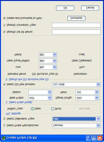
6 Easy to use Specify: cal kit name, connector type, and description for downloading to PNA 6

7 Automatically determines default: frequency range, cal type, and cal kit. User can easily change defaults. 7

8 Leads user through measurements of each cal standard in TRL kit Or Load previous measurements. 8

9 Verifies actual frequency ranges of standards and compares to design goals. Easy to update the cal kit definition. 9
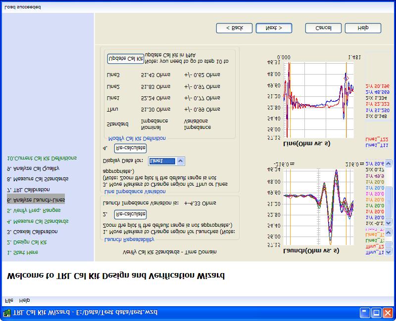

10 10

11 Expected performance Repeatability After TRL calibration 11

12 Cal kit definition: Kept up to date Easy to change One click download to PNA 12
13 Normally a SOLT/ECal removes the adapter Originally used for non-insertable devices An adapter is needed to provide thru calibration Like doing two calibrations to remove the effects of the adapter A TRL for one port and ECal (SOLT) for one port One port is ECal (coax reference) Second port is TRL (TRL reference center of thru) After completing the adapter removal cal, measure the thru. The result is ½the thru, which is the fixture. Save the.s2p file and you have the de-embed file Measure your DUT (with fixtures) and de-embed with file created above 13
14 To PNA To PNA Fixture Fixture ECal Reference Plane port 1 TRL Reference Plane port 2 14

15 The blue trace is a measurement of a backplane with fixture cards (red circle). The red trace is the same measurement with a TRL calibration fixture removed. The green trace is the blue trace with fixture de-embedded (S2p file from 2-tier calibration. De-embed TRL Ecal 15
16 Left Half Fixture Right Half Fixture DUT THRU fixture Connect left and right fixture halves. 16
17 Assumptions: Symmetric right to left Symmetric top to bottom No mode conversion Steps: 1.Calibrate at cable ends (4-port) 2.Measure fixture and save file 3.Measure fixtured DUT 4.Remove fixture Technique presented in paper at Design Con 2007 by Vahe Adamian 17

18 Open a 4 port DUT+Thru Fixture file in PLTS (Only 4 port is supported) In PLTS Menu Utilities Automatic Fixture Removal Select a Thru Fixture file, then Apply, the thru Fixture will be removed from opened DUT+Thru Fixture file. 18
19 4-port TRL Calibration Technique Fixture may be asymmetric Similar assumptions to single ended TRL Repeatability of connector, launch, and line lines are usable 20 to 160 degrees relative to thru Additional Differential Constraints SDDnm and SCDnm < -30 db Skew between lines < 10 degrees Open DUT Thru Line 3 Line 2 Line 1 19


20 PNA Cal Blue Thru Fixture Removal - Red Differential Crosstalk Cal - Green PNA Cal Blue Thru Fixture Removal - Red Differential Crosstalk Cal - Green Differential Crosstalk cal and Fixture removal give very similar results, removing the effect of the fixtures. Measuring the resonance incorrectly can imply significantly more loss that really exists in the device. 20


21 PNA Cal Blue Thru Fixture Removal - Red Differential Crosstalk Cal - Green PNA Cal Blue Thru Fixture Removal - Red Differential Crosstalk Cal - Green Offset is due to coupling that was ignored in the single ended calibration. 21
22 Probe calibrations are more prone to errors than coaxial calibrations and can take a longer time to complete. Multiport calibrations have many standards to connect multiple times and are also prone to errors. Ecal calibrations are less prone to errors. Help is needed in verifying these calibrations and recovering from an error with the least amount of additional time and work. 22
23 The first step is to be able to look at all the computed error terms to check for errors. Second is being able to look at the measurements of the individual cal standards to help find which one(s) are bad. Third, a quick way to repair (refresh) the bad calibration is needed 23


24 1. Load calset from PNA. 2. Inspect error terms. 24


25 1. Scroll through traces. 2. Problem with port Directivity is bad - probably load measurement. 25


26 1. Indeed it looks like the load on port 5 was wrong. 26


27 1. Indeed it looks like the load on port 5 was wrong. 2. Switching to polar or smith chart views will show a short was connected by mistake. 27

28 1. Browse to saved file with standards measurements. 2. Download raw measurements to PNA 28

29 1. Re-measure just the bad standard 2. Click Next to re-calculate error terms. 3. Ready to Measure DUT. 29
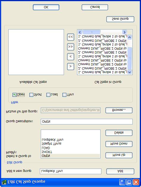
30 Creating Cal Kit definitions for probes and substrates can be challenging. Finding data that came with probes Multiple calibration standards on the ISS Loop back thrus for dual probes Multiport Calibration Challenges Grouping of cal steps Custom bitmaps for clarity 30


31 1. Use Straight Thru for the thru definitions. 2. Then specify Unknown Thru for loop back thru paths for best accuracy. 31
32 32

33 Two connector types will be created in the cal kit. Use one connector type for the upper two ports, another for the lower two ports. 33

34 34
35 Use an existing design (differential) Try automatic fixture removal with a thru artifact Quantify its characteristics Compare with single ended TRL Use data from multiple domains to better understand what we have Troubleshooting the measurement issue 35

36 TRL Reference Plane 36

37 TRL Reference Plane 37


38 Good repeatability of connectors, launches, and line impedance Phase Skew is less than 10 degrees (8 degrees) 38


39 Mode conversion is less than 30 db Differential match nearly symmetric 39


40 Appears to be a problem with differential port 2 more ringing Appears to be a problem with single ended port 2 connector 40

41 Resonance in S21 path 41

42 Automatic Fixture removal also removes coupling SOLT Calibration includes fixture TRL calibration removes fixture but not coupling 42

43 Automatic Fixture removal also removes coupling. TRL calibration removes fixture but not coupling. SOLT Calibration includes fixture. 43
44 Discussed additional calibration and fixture removal techniques beyond single ended TRL Discussed some problems and solutions for probed measurements and multimode measurements Provided some insight into analysis of measurements. 44
In-situ Port Cal for Dual Carriages Tuner
 In-situ Port Cal for Dual Carriages Tuner In-Situ port cal method is the calibration technique mainly for cascaded tuners or multi-carriage tuner. Unlike in-situ system cal which requires 2 VNA calibrations
Procedures to Characterize Maury s Automatic Tuner Using ATS Software Version 5.1 or above
 Procedures to Characterize Maury s Automatic Tuner Using ATS Software Version 5.1 or above Things to check before tuner characterization Make sure tuner is power up and USB cable is connected to the computer
Keysight Technologies De-Embedding and Embedding S-Parameter Networks Using a Vector Network Analyzer. Application Note
 Keysight Technologies De-Embedding and Embedding S-Parameter Networks Using a Vector Network Analyzer Application Note L C Introduction Traditionally RF and microwave components have been designed in packages
A Simple, Yet Powerful Method to Characterize Differential Interconnects
 A Simple, Yet Powerful Method to Characterize Differential Interconnects Overview Measurements in perspective The automatic fixture removal (AFR) technique for symmetric fixtures Automatic Fixture Removal
Senior Project Manager / AEO
 Kenny Liao 2018.12.18&20 Senior Project Manager / AEO Measurement Demo Prepare instrument for measurement Calibration Fixture removal Conclusion What next? Future trends Resources Acquire channel data
Practical De-embedding for Gigabit fixture. Ben Chia Senior Signal Integrity Consultant 5/17/2011
 Practical De-embedding for Gigabit fixture Ben Chia Senior Signal Integrity Consultant 5/17/2011 Topics Why De-Embedding/Embedding? De-embedding in Time Domain De-embedding in Frequency Domain De-embedding
Measurement Accuracy of the ZVK Vector Network Analyzer
 Product: ZVK Measurement Accuracy of the ZVK Vector Network Analyzer Measurement deviations due to systematic errors of a network analysis system can be drastically reduced by an appropriate system error
30 GHz Attenuator Performance and De-Embedment
 30GHz De-Embedment Application Note - Page 1 of 6 Theory of De-Embedment. Due to the need for smaller packages and higher signal integrity a vast majority of todays RF and Microwave components are utilizing
PCB Probing for Signal-Integrity Measurements
 TITLE PCB Probing for Signal-Integrity Measurements Richard Zai, PacketMicro Image PCB Probing for Signal-Integrity Measurements Richard Zai, PacketMicro Richard Zai, Ph.D. CTO, PacketMicro rzai@packetmicro.com
RF Characterization Report
 HDBNC Series RF Connector HDBNC-J-P-GN-ST-EM1 HDBNC-J-P-GN-ST-BH1 HDBNC-J-P-GN-ST-TH1 Description: 75 Ohm True 75 TM High Density BNC Straight Jack, Edge Mount or Through-hole Samtec Inc. WWW.SAMTEC.COM
Keysight Technologies
 Keysight Technologies A Simple, Powerful Method to Characterize Differential Interconnects Application Note Abstract The Automatic Fixture Removal (AFR) process is a new technique to extract accurate,
De-embedding Gigaprobes Using Time Domain Gating with the LeCroy SPARQ
 De-embedding Gigaprobes Using Time Domain Gating with the LeCroy SPARQ Dr. Alan Blankman, Product Manager Summary Differential S-parameters can be measured using the Gigaprobe DVT30-1mm differential TDR
Keysight Method of Implementation (MOI) for VESA DisplayPort (DP) Standard Version 1.3 Cable-Connector Compliance Tests Using E5071C ENA Option TDR
 for VESA DisplayPort (DP) Standard Version 1.3 Cable-Connector Compliance Tests Using E5071C ENA Option TDR") Revision 1.00 February 27, 2015 Keysight Method of Implementation (MOI) for VESA DisplayPort (DP) Standard Version 1.3 Cable-Connector Compliance Tests Using E5071C ENA Option TDR 1 Table of Contents 1.
Revision 1.00 February 27, 2015 Keysight Method of Implementation (MOI) for VESA DisplayPort (DP) Standard Version 1.3 Cable-Connector Compliance Tests Using E5071C ENA Option TDR 1 Table of Contents 1.
GT Dual-Row Nano Vertical Thru-Hole High Speed Characterization Report For Differential Data Applications
 GT-16-97 Dual-Row Nano Vertical Thru-Hole For Differential Data Applications 891-007-15S Vertical Thru-Hole PCB 891-001-15P Cable Mount Revision History Rev Date Approved Description A 8/31/2016 R. Ghiselli/G.
Microwave Interconnect Testing For 12G-SDI Applications
 DesignCon 2016 Microwave Interconnect Testing For 12G-SDI Applications Jim Nadolny, Samtec jim.nadolny@samtec.com Corey Kimble, Craig Rapp Samtec OJ Danzy, Mike Resso Keysight Boris Nevelev Imagine Communications
Application Note AN39
 AN39 9380 Carroll Park Drive San Diego, CA 92121, USA Tel: 858-731-9400 Fax: 858-731-9499 www.psemi.com Vector De-embedding of the PE42542 and PE42543 SP4T RF Switches Introduction Obtaining accurate measurement
RF Characterization Report
 CJT Series Circular RF Twinax Jack CJT-T-P-HH-ST-TH1 CJT-T-P-HH-RA-BH1 Mated With C28S-XX.XX-SPS8-SPS8 Description: Fully Mated Circular RF Shielded Twisted Pair Twinax Cable Assembly Samtec Inc. WWW.SAMTEC.COM
GT Dual-Row Nano Vertical SMT High Speed Characterization Report For Differential Data Applications
 GT-16-95 Dual-Row Nano Vertical SMT For Differential Data Applications 891-011-15S Vertical SMT PCB 891-001-15P Cable Mount Revision History Rev Date Approved Description A 6/3/2016 R. Ghiselli/D. Armani
Monoblock RF Filter Testing SMA, In-Fixture Calibration and the UDCK
 Application Note AN1008 Introduction Monoblock RF Filter Testing SMA, In-Fixture Calibration and the UDCK Factory testing needs to be accurate and quick. While the most accurate (and universally available)
Keysight N1055A Remote Head Module 35/50 GHz 2/4 Port TDR/TDT
 Keysight N1055A Remote Head Module 35/50 GHz 2/4 Port TDR/TDT For the 86100D DCA-X Series Oscilloscope Mainframe Data Sheet Engineered for easy, accurate impedance and S-parameter measurements on multi-port
Basic Verification of Power Loadpull Systems
 MAURY MICROWAVE 1 Oct 2004 C O R P O R A T I O N Basic Verification of Power Loadpull Systems Author: John Sevic, MSEE Automated Tuner System Technical Manager, Maury Microwave Corporation What is Loadpull
Agilent MOI for HDMI 1.4b Cable Assembly Test Revision Jul 2012
 Revision 1.11 19-Jul 2012 Agilent Method of Implementation (MOI) for HDMI 1.4b Cable Assembly Test Using Agilent E5071C ENA Network Analyzer Option TDR 1 Table of Contents 1. Modification Record... 4 2.
Why Engineers Ignore Cable Loss
 Why Engineers Ignore Cable Loss By Brig Asay, Agilent Technologies Companies spend large amounts of money on test and measurement equipment. One of the largest purchases for high speed designers is a real
Zen and the Art of On-Wafer Probing A Personal Perspective
 Zen and the Art of On-Wafer Probing A Personal Perspective Rob Sloan School E&EE, University of Manchester - after Robert Pirsig Device or Circuit Measurement at Microwave/ Millimetre-wave/ THz frequencies
User s Guide Rev 1.0
 User s Guide Rev 1.0 Plug and Play Kit for De-Embedding Software Algorithms Verification Evaluate the Accuracy of De-Embedding Algorithms Purchase Kits Direct from DVT Solutions, LLC Brian Shumaker sales@gigaprobes.com
SCSI Cable Characterization Methodology and Systems from GigaTest Labs
 lide - 1 CI Cable Characterization Methodology and ystems from GigaTest Labs 134. Wolfe Rd unnyvale, CA 94086 408-524-2700 www.gigatest.com lide - 2 Overview Methodology summary Fixturing Instrumentation
Agilent FieldFox RF Analyzer N9912A
 Contents Agilent FieldFox RF Analyzer N9912A Quick Reference Guide Do You Have Everything?... 2 The Power Button and LED... 2 Battery Usage... 3 Measure Return Loss... 4 Measure Cable Loss (1-Port)...
Keysight Technologies Method of Implementation (MOI) for BroadR-Reach Link Segment Tests Using E5071C ENA Option TDR
 for BroadR-Reach Link Segment Tests Using E5071C ENA Option TDR") Revision 2.00 August 28, 2014 BroadR-Reach Link Segment Keysight Technologies Method of Implementation (MOI) for BroadR-Reach Link Segment Tests Using E5071C ENA Option TDR 1 Table of Contents 1. Revision
Revision 2.00 August 28, 2014 BroadR-Reach Link Segment Keysight Technologies Method of Implementation (MOI) for BroadR-Reach Link Segment Tests Using E5071C ENA Option TDR 1 Table of Contents 1. Revision
Agilent Validating Transceiver FPGAs Using Advanced Calibration Techniques. White Paper
 Agilent Validating Transceiver FPGAs Using Advanced Calibration Techniques White Paper Contents Overview...2 Introduction...3 FPGA Applications Overview...4 Typical FPGA architecture...4 FPGA applications...5
Keysight Technologies High Power Ampliier Measurements Using Nonlinear Vector Network Analyzer. Application Note
 Keysight Technologies High Power Ampliier Measurements Using Nonlinear Vector Network Analyzer Application Note Introduction High-power devices are common building blocks in RF and microwave communication
SI Analysis & Measurement as easy as mobile apps ISD, ADK, X2D2
 SI Analysis & Measurement as easy as mobile apps ISD, ADK, X2D2 Ching-Chao Huang huang@ataitec.com Outline Can SI tools be made like mobile apps? Introduction of AtaiTec SI software Most applications in
APM CALIBRATION PROCEDURE Rev. A June 3, 2015
 APM CALIBRATION PROCEDURE Rev. A June 3, 2015 Calibration of the APM allows system parameters such as coupler coupling values, interconnecting cable losses and system feeder losses to be programmed into
Agilent 8510XF Vector Network Analyzer Single-Connection, Single-Sweep Systems Product Overview
 Agilent 8510XF Vector Network Analyzer Single-Connection, Single-Sweep Systems Product Overview Discontinued Product Information For Support Reference Only Information herein, may refer to products/services
MM-wave Partial Information De-embedding: Errors and Sensitivities. J. Martens
 MM-wave Partial Information De-embedding: Errors and Sensitivities J. Martens MM-wave Partial Information De-embedding: Errors and Sensitivities J. Martens Anritsu Company, Morgan Hill CA US Abstract De-embedding
Performance at the DUT: Techniques for Evaluating the Performance of an ATE System at the Device Under Test Socket
 DesignCon 2008 Performance at the DUT: Techniques for Evaluating the Performance of an ATE System at the Device Under Test Socket Heidi Barnes, Verigy, heidi.barnes@verigy.com Jose Moreira, Verigy, jose.moreira@verigy.com
Microwave Interconnect Testing For 12G SDI Applications
 TITLE Microwave Interconnect Testing For 12G SDI Applications Jim Nadolny, Samtec Image Corey Kimble, Craig Rapp - Samtec OJ Danzy, Mike Resso - Keysight Boris Nevelev - Imagine Communications Microwave
Virtual Thru-Reflect-Line (TRL) Calibration
 Calibration") Virtual Thru-Reflect-Line (TRL) By John E. Penn Introduction In measuring circuits at microwave frequencies, it is essential to have a known reference plane, particularly when measuring transistors whose
Virtual Thru-Reflect-Line (TRL) By John E. Penn Introduction In measuring circuits at microwave frequencies, it is essential to have a known reference plane, particularly when measuring transistors whose
Agilent 87075C 75 Ohm Multiport Test Sets for use with Agilent E5061A ENA-L Network Analyzers
 Agilent 87075C 75 Ohm Multiport Test Sets for use with Agilent E5061A ENA-L Network Analyzers Technical Overview Focus on testing, not reconnecting! Maximize production throughput of cable-tv multiport
Viavi T-BERD 5800 CPRI Testing Guide with ALU BBU Emulation
 Viavi T-BERD 5800 CPRI Testing Guide with ALU BBU Emulation Scope Version 4 January 2018 Firmware 26.0.0.6c1973b or Later REQUIRED! This document describes Common Public Radio Interface (CPRI) testing
Analyze Frequency Response (Bode Plots) with R&S Oscilloscopes Application Note
 with R&S Oscilloscopes Application Note") Analyze Frequency Response (Bode Plots) with R&S Oscilloscopes Application Note Products: R&S RTO2002 R&S RTO2004 R&S RTO2012 R&S RTO2014 R&S RTO2022 R&S RTO2024 R&S RTO2044 R&S RTO2064 This application
Analyze Frequency Response (Bode Plots) with R&S Oscilloscopes Application Note Products: R&S RTO2002 R&S RTO2004 R&S RTO2012 R&S RTO2014 R&S RTO2022 R&S RTO2024 R&S RTO2044 R&S RTO2064 This application
INTRODUCTION This procedure should only be performed if the instrument fails to meet the Performance Check tests for Output Zero or Offset Accuracy
 INTRODUCTION This procedure should only be performed if the instrument fails to meet the Performance Check tests for Output Zero or Offset Accuracy (steps A and B). Gain, which affects DC Accuracy, cannot
DESIGN!!GUIDELINES!!!!!
 DESIGNGUIDELINES 1 2 3 4 5 6 7 8 9 10 11 12 13 14 15 16 17 18 19 20 21 22 23 24 25 26 27 28 29 30 31 32 33 34 35 36 37 38 39 40 41 42 43 44 45 46 1. Testing General 1.1. For acceptance, 100% of the media
SI Design & Measurement Principles and Best Practices
 I ment Principles and Best Practices 13 May, 2015 Heidi Barnes enior Application Engineer High peed Digital Design Keysight EEof EDA Division In collaboration with: Ben Chia enior ignal Integrity Consultant
ENGINEERING COMMITTEE Interface Practices Subcommittee AMERICAN NATIONAL STANDARD ANSI/SCTE
 ENGINEERING COMMITTEE Interface Practices Subcommittee AMERICAN NATIONAL STANDARD ANSI/SCTE 48-3 2011 Test Procedure for Measuring Shielding Effectiveness of Braided Coaxial Drop Cable Using the GTEM Cell
Transmitter Interface Program
 Transmitter Interface Program Operational Manual Version 3.0.4 1 Overview The transmitter interface software allows you to adjust configuration settings of your Max solid state transmitters. The following
#P46. Time Domain Reflectometry. Q: What is TDR and how does it work?
 #P46 Time Domain Reflectometry is a technique used to determine the signal s distance from source to load. The delay found inherent in the environment can be compensated for through automatic calibration,
Forensic Analysis of Closed Eyes
 Forensic Analysis of Closed Eyes Dr. Eric Bogatin, Dean, Teledyne LeCroy Signal Integrity Academy Stephen Mueller, Applications Engineering Manager, Teledyne LeCroy Karthik Radhakrishna, Applications Engineer,
Limitations of On-Wafer Calibration and De-Embedding Methods in the Sub-THz Range
 Journal of Computer and Communications, 2013, 1, 25-29 Published Online November 2013 (http://www.scirp.org/journal/jcc) http://dx.doi.org/1236/jcc.2013.16005 25 Limitations of On-Wafer Calibration and
RF Characterization Report
 BNC7T-J-P-xx-ST-EMI BNC7T-J-P-xx-RD-BH1 BNC7T-J-P-xx-ST-TH1 BNC7T-J-P-xx-ST-TH2D BNC7T-J-P-xx-RA-BH2D Mated with: RF179-79SP1-74BJ1-0300 Description: 75 Ohm BNC Board Mount Jacks Samtec, Inc. 2005 All
DUT ATE Test Fixture S-Parameters Estimation using 1x-Reflect Methodology
 DUT ATE Test Fixture S-Parameters Estimation using 1x-Reflect Methodology Jose Moreira, Advantest Ching-Chao Huang, AtaiTec Derek Lee, Nvidia Conference Ready mm/dd/2014 BiTS China Workshop Shanghai September
Quick Start for TrueRTA (v3.5) on Windows XP (and earlier)
 on Windows XP (and earlier)") Skip directly to the section that covers your version of Windows (XP and earlier, Vista or Windows 7) Quick Start for TrueRTA (v3.5) on Windows XP (and earlier) Here are step-by-step instructions to get
Skip directly to the section that covers your version of Windows (XP and earlier, Vista or Windows 7) Quick Start for TrueRTA (v3.5) on Windows XP (and earlier) Here are step-by-step instructions to get
SignalCorrect Software and TCS70902 Calibration Source Option SC SignalCorrect software
 SignalCorrect Software and TCS70902 Calibration Source Option SC SignalCorrect software Eye of signal after de-embed using SignalCorrect Features and benefits Measurement and de-embed: Characterize cables
Basic RF Amplifier Measurements using the R&S ZNB Vector Network Analyzer and SMARTerCal. Application Note
 Basic RF Amplifier Measurements using a R&S ZNB Analyzer and SMARTerCal Mark Bailey 2013-03-05, 1ES, Version 1.0 Basic RF Amplifier Measurements using the R&S ZNB Vector Network Analyzer and SMARTerCal.
ENGINEERING COMMITTEE Interface Practices Subcommittee AMERICAN NATIONAL STANDARD ANSI/SCTE Mainline Pin (plug) Connector Return Loss
 Connector Return Loss") ENGINEERING COMMITTEE Interface Practices Subcommittee AMERICAN NATIONAL STANDARD ANSI/SCTE 125 2007 Mainline Pin (plug) Connector Return Loss NOTICE The Society of Cable Telecommunications Engineers (SCTE)
ENGINEERING COMMITTEE Interface Practices Subcommittee AMERICAN NATIONAL STANDARD ANSI/SCTE 125 2007 Mainline Pin (plug) Connector Return Loss NOTICE The Society of Cable Telecommunications Engineers (SCTE)
Manual Supplement. This supplement contains information necessary to ensure the accuracy of the above manual.
 Manual Title: 9500B Users Supplement Issue: 2 Part Number: 1625019 Issue Date: 9/06 Print Date: October 2005 Page Count: 6 Version 11 This supplement contains information necessary to ensure the accuracy
Keysight FieldFox Microwave Analyzers
 Quick Reference Guide Contents Keysight FieldFox Microwave Analyzers Do you have everything?... 1 The Power Button and LED... 1 Battery Usage... 2 Measure Return Loss (CAT Mode)... 3 Measure 1-Port Cable
USB-TG124A Tracking Generator User Manual
 USB-TG124A Tracking Generator User Manual Signal Hound USB-TG124A User Manual 2017, Signal Hound, Inc. 35707 NE 86th Ave La Center, WA 98629 USA Phone 360.263.5006 Fax 360.263.5007 This information is
Intel PCB Transmission Line Loss Characterization Metrology
 Report to IPC D24D: Intel PCB Transmission Line Loss Characterization Metrology Xiaoning Ye, Key Contributors: Jimmy Hsu, Kai Xiao, et al. 1 Background Current IPC test methods under TM-650 are not adequate
Autopilot II Quick Setup
 ! Autopilot II Quick Setup Background 3 How Autopilot Works 3 Autopilot Terms and Definitions 3 DMX512 Channel Assignments 4 Hardware Installation 5 Receiver Installation 5 Spotlight Installation 5 Autopilot
Electrical Sampling Modules Datasheet 80E11 80E11X1 80E10B 80E09B 80E08B 80E07B 80E04 80E03 80E03-NV
 Electrical Sampling Modules Datasheet 80E11 80E11X1 80E10B 80E09B 80E08B 80E07B 80E04 80E03 80E03-NV The DSA8300 Series Sampling Oscilloscope, when configured with one or more electrical sampling modules,
Electrical Sampling Modules
 Electrical Sampling Modules 80E11 80E11X1 80E10B 80E09B 80E08B 80E07B 80E04 80E03 80E03-NV Datasheet Applications Impedance Characterization and S-parameter Measurements for Serial Data Applications Advanced
Precision TNC Coaxial Calibration Kit
 User Guide Precision TNC Coaxial Calibration Kit DC to 18 GHz Models: 8650CK10/11 8650CK20/21 8650-511 (A) 2/15 User Guide Precision TNC Coaxial Calibration Kit DC to 18 GHz Models: 8650CK10/11 8650CK20/21
Introduction to the new software V230 for the minivna
 Introduction to the new software V230 for the minivna Many thanks go to Harry DK3SI and Stewart G3RXQ for their fast and extensive work, started mid May 2007. Beta-Test early June. Final version released
R&S ZN-Z32/-Z33 Automatic In-line Calibration Modules Ensuring high accuracy with thermal vacuum testing and multiport measurements
 R&S ZN-Z32/-Z33 Automatic In-line Calibration Modules Ensuring high accuracy with thermal vacuum testing and multiport measurements Product Brochure Version 01.01 R&S ZN-Z32/-Z33 Automatic In-Line Calibration
Exercise 5. Troubleshooting a QAM/DQAM Modem EXERCISE OBJECTIVE DISCUSSION OUTLINE DISCUSSION. Signal flow tracing
 Exercise 5 Troubleshooting a QAM/DQAM Modem EXERCISE OBJECTIVE When you have completed this exercise, you will have acquired an efficient procedure for troubleshooting instructor-inserted faults in the
Interface Practices Subcommittee SCTE STANDARD SCTE Hard Line Pin Connector Return Loss
 Interface Practices Subcommittee SCTE STANDARD SCTE 125 2018 Hard Line Pin Connector Return Loss NOTICE The Society of Cable Telecommunications Engineers (SCTE) / International Society of Broadband Experts
Mortara X-Scribe Tango+ Interface Notes
 Mortara X-Scribe Tango+ Interface Notes To setup Tango+ with the X-Scribe stress system, simply follow the directions below. 1. Verify Correct RS-232 and ECG Trigger Cables RS-232 Cable used to communicate
ENGINEERING COMMITTEE
 ENGINEERING COMMITTEE Interface Practices Subcommittee AMERICAN NATIONAL STANDARD ANSI/SCTE 04 2014 Test Method for F Connector Return Loss NOTICE The Society of Cable Telecommunications Engineers (SCTE)
GE CardioSoft (Version 6.01 or higher) Tango M2 Interface Notes
 Tango M2 Interface Notes") GE CardioSoft (Version 6.01 or higher) Tango M2 Interface Notes To setup Tango M2 with your CardioSoft (V6.01 or higher), simply follow the directions below. 1. Verify Correct RS-232 and ECG Trigger Cables
GE CardioSoft (Version 6.01 or higher) Tango M2 Interface Notes To setup Tango M2 with your CardioSoft (V6.01 or higher), simply follow the directions below. 1. Verify Correct RS-232 and ECG Trigger Cables
S-Parameter Measurement and Fixture De-Embedding Variation Across Multiple Teams, Equipment and De- Embedding Tools
 DesignCon 2019 S-Parameter Measurement and Fixture De-Embedding Variation Across Multiple Teams, Equipment and De- Embedding Tools Heidi Barnes, Keysight Technologies, heidi.barnes@keysight.com Eric Bogatin,
Agilent N6467A BroadR-Reach Compliance Test Application. Methods of Implementation
 Agilent N6467A BroadR-Reach Compliance Test Application Methods of Implementation s1 Notices Agilent Technologies, Inc. 2013 No part of this manual may be reproduced in any form or by any means (including
Using SignalTap II in the Quartus II Software
 White Paper Using SignalTap II in the Quartus II Software Introduction The SignalTap II embedded logic analyzer, available exclusively in the Altera Quartus II software version 2.1, helps reduce verification
Welch Allyn CardioPerfect Workstation Tango+ Interface Notes
 Welch Allyn CardioPerfect Workstation Tango+ Interface Notes To setup Tango+ with the CardioPerfect stress system, simply follow the directions below. 1. Verify Correct RS-232 and ECG Trigger Cables RS-232
LMH0340/LMH0341 SerDes EVK User Guide
 LMH0340/LMH0341 SerDes EVK User Guide July 1, 2008 Version 1.05 1 1... Overview 3 2... Evaluation Kit (SD3GXLEVK) Contents 3 3... Hardware Setup 4 3.1 ALP100 BOARD (MAIN BOARD) DESCRIPTION 5 3.2 SD340EVK
Agilent 4-Port PNA-L Microwave Network Analyzer
 Agilent 4-Port PNA-L Microwave Network Analyzer N523A 3 khz to 13.5, 2 GHz Data Sheet Note: Specification information in this document is also available within the PNA-L network analyzer s internal Help
Fiber Optic Testing. The FOA Reference for Fiber Optics Fiber Optic Testing. Rev. 1/31/17 Page 1 of 12
 Fiber Optic Testing Testing is used to evaluate the performance of fiber optic components, cable plants and systems. As the components like fiber, connectors, splices, LED or laser sources, detectors and
DesignCon Tips and Advanced Techniques for Characterizing a 28 Gb/s Transceiver
 DesignCon 2013 Tips and Advanced Techniques for Characterizing a 28 Gb/s Transceiver Jack Carrel, Robert Sleigh, Agilent Technologies Heidi Barnes, Agilent Technologies Hoss Hakimi, Mike Resso, Agilent
Chapter 6 Tuners. How is a tuner build: In it's most simple form we have an inductor and a capacitor. One in shunt and one in series.
 Chapter 6 Tuners Because most users on the VWNA group are also HAM, I will do some chapters on HAM related gear. But not to worry, a tuner is something you use in most RF designs. A tuner is just a device
Agilent 87075C Multiport Test Set Product Overview
 Agilent 87075C Multiport Test Set Product Overview A complete 75 ohm system for cable TV device manufacturers Now, focus on testing, not reconnecting! For use with the Agilent 8711 C-Series of network
The Measurement Tools and What They Do
 2 The Measurement Tools The Measurement Tools and What They Do JITTERWIZARD The JitterWizard is a unique capability of the JitterPro package that performs the requisite scope setup chores while simplifying
HITS QT/QT+ Setup Instructions for QSD/QHD Services using: Drake SCT2x4 Headend Transcoder 2 Satellites/4 Multiplexes
 HITS QT/QT+ Setup Instructions for QSD/QHD Services using: Drake SCT2x4 Headend Transcoder 2 Satellites/4 Multiplexes Drake Transcoder Front /Rear View Setup and Programming Instructions: Input Setup Below
NDT Supply.com 7952 Nieman Road Lenexa, KS USA
 ETher ETherCheck Combined Eddy Current & Bond Testing Flaw Detector The ETherCheck is a combined Eddy Current and Bond Testing Flaw Detector which comes with a rich range of features offered by a best
T-Check Software from R&S and how to install: In the following is a small guide how to install and use the Software:
 How to check the calibration and accuracy of the VNWA using the T-Check Software 1. T-Check Software from R&S and how to install 2. How to generate S2P files from VNWA for use by T-Check Software from
MSO-28 Oscilloscope, Logic Analyzer, Spectrum Analyzer
 Link Instruments Innovative Test & Measurement solutions since 1986 Store Support Oscilloscopes Logic Analyzers Pattern Generators Accessories MSO-28 Oscilloscope, Logic Analyzer, Spectrum Analyzer $ The
SDLA Visualizer Serial Data Link Analysis Visualizer Software Printable Application Help
 SDLA Visualizer Serial Data Link Analysis Visualizer Software Printable Application Help *P076017306* 076-0173-06 SDLA Visualizer Serial Data Link Analysis Visualizer Software Printable Application Help
Amplifier Measurement Wizard Operation Manual
 Agilent ENA Series Network Analyzers Amplifier Measurement Wizard Operation Manual Rev. 01.40 January 2011 Notices The information contained in this document is subject to change without notice. This document
Designing High Performance Interposers with 3-port and 6-port S-parameters
 DesignCon 2015 Designing High Performance Interposers with 3-port and 6-port S-parameters Joseph Socha, Nexus Technology joe.socha@nexustechnology.com Jonathan Dandy, Tektronix jonathan.s.dandy@tektronix.com
apple Service Source Apple Cinema HD Display 23" LCD (ADC) 11 April Apple Computer, Inc. All rights reserved.
 11 April Apple Computer, Inc. All rights reserved.") apple Service Source Apple Cinema HD Display 23" LCD (ADC) 11 April 2003 2003 Apple Computer, Inc. All rights reserved. apple Service Source Take Apart Apple Cinema HD Display 23" LCD (ADC) 2003 Apple
apple Service Source Apple Cinema HD Display 23" LCD (ADC) 11 April 2003 2003 Apple Computer, Inc. All rights reserved. apple Service Source Take Apart Apple Cinema HD Display 23" LCD (ADC) 2003 Apple
4 MHz Lock-In Amplifier
 4 MHz Lock-In Amplifier SR865A 4 MHz dual phase lock-in amplifier SR865A 4 MHz Lock-In Amplifier 1 mhz to 4 MHz frequency range Low-noise current and voltage inputs Touchscreen data display - large numeric
T-BERD /MTS 5800 Network Tester Fiber Channel Layer 2 Traffic
 Quick Card T-BERD /MTS 5800 Network Tester Fiber Channel Layer 2 Traffic This quick card outlines how to configure and run a Fiber Channel Layer 2 Traffic Test with a recommended test suite of Throughput,
Boosting Performance Oscilloscope Versatility, Scalability
 Boosting Performance Oscilloscope Versatility, Scalability Rising data communication rates are driving the need for very high-bandwidth real-time oscilloscopes in the range of 60-70 GHz. These instruments
Agilent Parallel Bit Error Ratio Tester. System Setup Examples
 Agilent 81250 Parallel Bit Error Ratio Tester System Setup Examples S1 Important Notice This document contains propriety information that is protected by copyright. All rights are reserved. Neither the
BLONDER TONGUE LABORATORIES, INC.
 BLONDER TONGUE LABORATORIES, INC. One Jake Brown Road, P.O. Box 1000 Tel: (732) 679-4000 Old Bridge, NJ 08857-1000 USA Fax: (732) 679-4353 DESIGNING THE DISTRIBUTION SYSTEM DISTRIBUTION SYSTEM Since the
apple Service Source Apple Studio Display 17" LCD (ADC) Updated 6 Decenber Apple Computer, Inc. All rights reserved.
 Updated 6 Decenber Apple Computer, Inc. All rights reserved.") apple Service Source Apple Studio Display 17" LCD (ADC) Updated 6 Decenber 2004 2003 Apple Computer, Inc. All rights reserved. apple Service Source Take Apart Apple Studio Display 17" LCD (ADC) 2003 Apple
apple Service Source Apple Studio Display 17" LCD (ADC) Updated 6 Decenber 2004 2003 Apple Computer, Inc. All rights reserved. apple Service Source Take Apart Apple Studio Display 17" LCD (ADC) 2003 Apple
Stevens SatComm FAQs For use with SatCommSet or Terminal Setup programs
 Stevens SatComm FAQs For use with SatCommSet or Terminal Setup programs Q. What are the channel assignments for On Air Test Mode? A. The assigned GOES test channels are as follows: GOES West 300 Baud:
Troubleshooting CS800/LC900 Bikes
 Troubleshooting CS800/LC900 Bikes CS800/900LC Bike Troubleshooting Entering the Maintenance Mode 15 Touch Screen: The Maintenance Mode is designed to help the tech determine certain faults in the upper
Eye Doctor II Advanced Signal Integrity Tools
 Eye Doctor II Advanced Signal Integrity Tools EYE DOCTOR II ADVANCED SIGNAL INTEGRITY TOOLS Key Features Eye Doctor II provides the channel emulation and de-embedding tools Adds precision to signal integrity
Mortara XScribe Versions 3.xx and 5.xx Tango M2 Interface Notes
 Mortara XScribe Versions 3.xx and 5.xx Tango M2 Interface Notes To setup Tango M2 with the XScribe cardiac stress system, simply follow the directions below. 1. Verify Correct RS-232 and ECG Trigger Cables
Standard Operating Procedure of nanoir2-s
 Standard Operating Procedure of nanoir2-s The Anasys nanoir2 system is the AFM-based nanoscale infrared (IR) spectrometer, which has a patented technique based on photothermal induced resonance (PTIR),
Limitations of a Load Pull System
 Limitations of a Load Pull System General Rule: The Critical Sections in a Load Pull measurement setup are the sections between the RF Probe of the tuners and the DUT. The Reflection and Insertion Loss