Modulate Magnetic Kit 10-07
|
|
|
- Alberta Paul
- 5 years ago
- Views:
Transcription


1 Modulate Magnetic Kit MOD M MOD M-OCE Modulate Fabric Banner kits feature unique angles and shapes, are portable and now are even easier to configure to achieve your dream space! Modulate now offers magnets to attach frames and keep them securely connected together. Choose from multiple frame shapes to design your own combinations walls, booths, conference rooms, storage areas the possibilities are endless! The aluminum tube frames feature snap-button and spigot connections that are coupled with a printed pillowcase fabric graphic that slips over the frame and zips closed at the bottom. Universal feet connect the tube frames at the bottom of the display. Each frame comes in a durable, portable carry bag. features and benefits: - Magnetized premium aluminum tube frame with spigot and snap button assembly - Easy to store and ship - Quick to set up - Weighted feet for added stability - Comes with carry bag and box dimensions: Hardware Assembled unit: w x 96 h x d 2580mm(w) x 2438mm(h) x 1179mm(d) Approximate weight: 31 lb / 14 kg - Zipper pillowcase fabric graphics - Lifetime limited hardware warranty against manufacturer defects Graphic Refer to related graphic template for more information. Visit: graphic-templates Shipping Packing Option 1: MOD M 1 Box: 48 l x 11 h x 4 d 1219mm(l) x 279mm(h) x 102mm(d) 1 Box: 60 l x 11 h x 4 d 1524mm(l) x 279mm(h) x 102mm(d) additional information: Graphic material: Dye-sublimation zipper pillowcase fabric When included in a larger kit, a different packaging solution will be listed to accommodate all contents of the kit. Individual packaging no longer provided. Approximate shipping weight: 35 lb / 16 kg Packing Option 2: MOD M-OCE We are continually improving and modifying our product range and reserve the right to vary the specifications without prior notice. All dimensions and weights quoted are approximate and we accept no responsibility for variance. E&OE. See Graphic Templates for graphic bleed specifications. 11/02/ OCE: Expandable case length (l) may vary l x 18 h x 18 d 1016mm-1677mm(l) x 458mm(h) x 458mm(d) Approximate shipping weight: 65 lb / 30 kg


2 Included In Your Kit MOD-FRM-01-M x1 MOD-FRM-08-M x1


3 Suggested Kit Layout MOD M MOD-FRM-01-M MOD-FRM-08-M

4 Modulate Frame 01 MOD-FRM-01-M Modulate Fabric Banners feature unique angles and shapes, are portable and now are even easier to configure to achieve your dream space! Modulate now offers magnets to attach frames and keep them securely connected together. Choose from multiple frame shapes to design your own combinations walls, booths, conference rooms, storage areas the possibilities are endless! The aluminum tube frames feature snap-button and spigot connections that are coupled with a printed pillowcase fabric graphic that slips over the frame and zips closed at the bottom. Universal feet connect the tube frames at the bottom of the display. Each frame comes in a durable, portable carry bag. features and benefits: - Magnetized premium aluminum tube frame with spigot and snap button assembly - Easy to store and ship - Quick to set up - Weighted feet for added stability - Comes with carry bag and box dimensions: Hardware Assembled unit: 60 w x 96 h x 19 d 1523mm(w) x 2438mm(h) x 484mm(d) Approximate weight: 15 lb / 7 kg - Zipper pillowcase fabric graphics - Lifetime limited hardware warranty against manufacturer defects Graphic Refer to related graphic template for more information. Visit: graphic-templates Shipping Packing box(es): 1 Box Box size: 60 l x 11 h x 4 d 1524mm(l) x 279mm(h) x 102mm(d) Approximate shipping weight: 17 lb / 8 kg additional information: Graphic material: Dye-sublimation zipper pillowcase fabric When included in a larger kit, a different packaging solution will be listed to accommodate all contents of the kit. Individual packaging no longer provided. We are continually improving and modifying our product range and reserve the right to vary the specifications without prior notice. All dimensions and weights quoted are approximate and we accept no responsibility for variance. E&OE. See Graphic Templates for graphic bleed specifications. 10/25/2017

5 Included In Your Kit Tools, Components, Connectors, Tubes & Graphics HEX KEY SET x1 ES30 x4 TC-30-90T x1 ES30-90B x2 LN114-SCRW x2 MOD-FRM-01-T1 x1 MOD-FRM-01-T4 x1 MOD-FRM-01-T5 x1 PLT-BP-LN114-S5-450 x2 MOD-FRM-01-T2-M-T x1 MOD-FRM-01-T2-M-B x2 MOD-FRM-01-T3-M-T x1 TUBE-STRAP-30-M x2 MOD-FRM-01-CC-LT-G x1 MOD-FRM-01-CV-LT-G x1 MOD-FRM-01-CC-RT-G x1 MOD-FRM-01-CV-RT-G x1
6 Exploded View MOD-FRM-01-M To assemble with curve left
7 Exploded View MOD-FRM-01-M To assemble with curve right
8 Labeling Diagram MOD-FRM-01-M To assemble with curve left
9 Labeling Diagram MOD-FRM-01-M To assemble with curve right


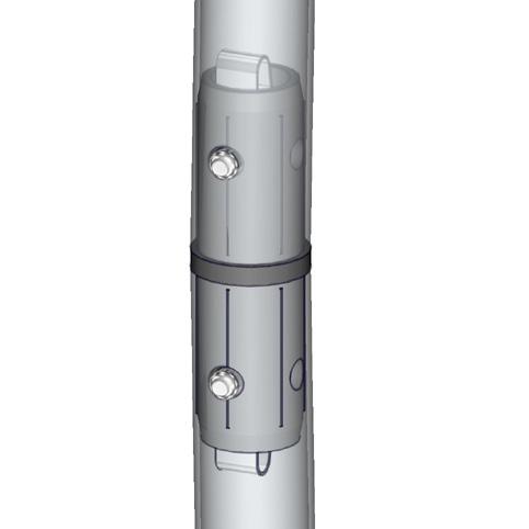
10 Connection Methods Connection Method 1: ES30 Connection Method 2: TC-30-90T For spigot connections, compress the unlocked connector and slide into the tube lock access hole. Lock both screws carefully using your allen key tool. Be sure to lock securely, but do not over tighten. Do not force the connection and be careful with the tube edges, they may be sharp. To disassemble, unlocked connector press the snap button and pull apart. Take the plastic connector and make sure the snap buttons are in proper position for the frame tube holes. Simply press the snap button with your thumb and carefully slide the tube onto the connector. The snap button should pop through. Some twisting may be necessary to assure the snap button has popped all the way through the tube hole. Do not force the connection and be careful with the tube edges, they may be sharp. Connection Method 3: ES30-90B Connection Method 4: TUBE-STRAP Compress one unlocked end of the connector and slide it through one tube end. Compress the other end of the connector and slide the second tube on. Lock both screws carefully using your allen key tool. Be sure to lock securely, but do not over tighten. The velcro tube straps add safety when handling the magnetized tubes before, during and after display setup. Follow these steps to bundle the magnetized tubes. First, place 1 tube into 2 strap pockets. Then, place the strap pockets over the labeled magnetized area on the tube. Next, firmly hold the tube and bundle the rest of the magnetized tubes together. The straps hold up to 4 tubes to make 1 bundle. Finally, take the hook velcro and wrap it around the tubes for a secure hold. tools, electronic devices, credit cards or any of the body, such as fingers, hands, etc,
11 Connection Methods Connection Method 5: PLT-BP-LN114-S5 Connection Method 6: PLT-BP-LN114-S5 ES30-90B Set Screw Set Screw M10 Insert ES30-90B 1 2A 2B First, loosen the set screw that is on the ES30-90B, then attach the base plate with the M10 insert. Once the base plate is in the desired position, fasten the set screw to hold the insert in place. There are two ways you can connect individual frames to make a back wall unit. (1A) The first thing to do is to loosen the set screw that is on the ES30-90B. Do not remove the set screw. Next, rotate the stabilizing base hole to the outside of the frame and tighten the set screw. (2A) Connecting magnet frames together is easy - the frames will simply magnetize to each other. Use caution when handling the magnetized frames. The frame will rest on the stabilizing base, covering the hole leaving a leveled finished look. (2B) When your frame does not feature magnets, you will have to use the provided ES30-90B set screw to fasten it onto the base. Don t forget to use your frame clip at the top to level the panels.


12 Kit Assembly Step by Step Step 1. Gather the components to build the frame. Use the Exploded View and the Labeling Diagram for part labels. Reference Connection Method(s) 1, 2, 3 and 4 for more details. Step 2. Locate your pillowcase graphic. With the pillowcase unzipped, encase the frame by covering the frame from top to bottom. Zipper at the bottom. Zipper Step 3. Locate the stabilizing bases. Attach each foot to the bottom ends of the frame. Use the allen key tool provided to lock the bases in place. Step 4. Setup is complete. If you are connecting frames side by side, reference Connection Method(s) 6 for more details. Reference Connection Method(s) 5 for more details.
13 Modulate Frame 08 MOD-FRM-08-M Modulate Fabric Banners feature unique angles and shapes, are portable and now are even easier to configure to achieve your dream space! Modulate now offers magnets to attach frames and keep them securely connected together. Choose from multiple frame shapes to design your own combinations walls, booths, conference rooms, storage areas the possibilities are endless! The aluminum tube frames feature snap-button and spigot connections that are coupled with a printed pillowcase fabric graphic that slips over the frame and zips closed at the bottom. Universal feet connect the tube frames at the bottom of the display. Each frame comes in a durable, portable carry bag. features and benefits: - Magnetized premium aluminum tube frame with spigot and snap button assembly - Easy to store and ship - Quick to set up - Weighted feet for added stability - Comes with carry bag and box dimensions: Hardware Assembled unit: 46.7 w x 92 h x d 1187mm(w) x 2337mm(h) x 450mm(d) Approximate weight: 16 lb / 8 kg - Zipper pillowcase fabric graphics - Lifetime limited hardware warranty against manufacturer defects Graphic Refer to related graphic template for more information. Visit: graphic-templates Shipping Packing box(es): 1 Box Box size: 48 l x 11 h x 4 d 1219mm(l) x 279mm(h) x 102mm(d) Approximate shipping weight: 18 lb / 9 kg additional information: Graphic material: Dye-sublimation zipper pillowcase fabric When included in a larger kit, a different packaging solution will be listed to accommodate all contents of the kit. Individual packaging no longer provided. We are continually improving and modifying our product range and reserve the right to vary the specifications without prior notice. All dimensions and weights quoted are approximate and we accept no responsibility for variance. E&OE. See Graphic Templates for graphic bleed specifications. 10/26/2017


14 Included In Your Kit Tools, Components, Connectors, Tubes & Graphics HEX KEY SET x1 PLT-BP-LN114-S5-450 x2 TC-30-S x2 LN114-SCRW x2 TC-30-90T x1 MOD-FRM-08-T2 x2 TC-30-T x2 MOD-FRM-08-T4 x1 ES30-90B x2 MOD-FRM-08-T5-M-T x1 MOD-FRM-08-T1-M-B x2 MOD-FRM-08-T1-M-T x1 MOD-FRM-08-T3-M-T x1 TUBE-STRAP-30-M x2 MOD-FRM-08-RT-G x1 MOD-FRM-08-LT-G x1
15 Exploded View MOD-FRM-08-M
16 Labeling Diagram MOD-FRM-08-M


17 Connection Methods Connection Method 1: TC-30-T Connection Method 2: TC-30-90T Take the plastic connector and make sure the snap buttons are in proper position for the frame tube holes. Simply press the snap button with your thumb and carefully slide the tube onto the connector. The snap button should pop through. Some twisting may be necessary to assure the snap button has popped all the way through the tube hole. Do not force the connection and be careful with the tube edges, they may be sharp. Take the plastic connector and make sure the snap buttons are in proper position for the frame tube holes. Simply press the snap button with your thumb and carefully slide the tube onto the connector. The snap button should pop through. Some twisting may be necessary to assure the snap button has popped all the way through the tube hole. Do not force the connection and be careful with the tube edges, they may be sharp. Connection Method 3: TC-30-S Connection Method 4: ES30-90B Take the plastic connector and make sure the snap buttons are in proper position for the frame tube holes. Simply press the snap button with your thumb and carefully slide the tube onto the connector. The snap button should pop through. Some twisting may be necessary to assure the snap button has popped all the way through the tube hole. Do not force the connection and be careful with the tube edges, they may be sharp. Compress one unlocked end of the connector and slide it through one tube end. Compress the other end of the connector and slide the second tube on. Lock both screws carefully using your allen key tool. Be sure to lock securely, but do not over tighten.
18 Connection Methods Connection Method 5: PLT-BP-LN114-S5 Connection Method 6: PLT-BP-LN114-S5 ES30-90B Set Screw Set Screw M10 Insert ES30-90B 1 2A 2B First, loosen the set screw that is on the ES30-90B, then attach the base plate with the M10 insert. Once the base plate is in the desired position, fasten the set screw to hold the insert in place. There are two ways you can connect individual frames to make a back wall unit. (1A) The first thing to do is to loosen the set screw that is on the ES30-90B. Do not remove the set screw. Next, rotate the stabilizing base hole to the outside of the frame and tighten the set screw. Connection Method 7: TUBE-STRAP (2A) Connecting magnet frames together is easy - the frames will simply magnetize to each other. Use caution when handling the magnetized frames. The frame will rest on the stabilizing base, covering the hole leaving a leveled finished look. (2B) When your frame does not feature magnets, you will have to use the provided ES30-90B set screw to fasten it onto the base. Don t forget to use your frame clip at the top to level the panels. The velcro tube straps add safety when handling the magnetized tubes before, during and after display setup. Follow these steps to bundle the magnetized tubes. First, place 1 tube into 2 strap pockets. Then, place the strap pockets over the labeled magnetized area on the tube. Next, firmly hold the tube and bundle the rest of the magnetized tubes together. The straps hold up to 4 tubes to make 1 bundle. Finally, take the hook velcro and wrap it around the tubes for a secure hold. tools, electronic devices, credit cards or any of the body, such as fingers, hands, etc,
 1, 2, 3, 4 and 7 for more details. Step 2. Locate your pillowcase graphic.")

19 Kit Assembly Step by Step Step 1. Gather the components to build the frame. Use the Exploded View and the Labeling Diagram for part labels. Reference Connection Method(s) 1, 2, 3, 4 and 7 for more details. Step 2. Locate your pillowcase graphic. With the pillowcase unzipped, encase the frame by covering the frame from top to bottom. Zipper at the bottom. Zipper Step 3. Locate the stabilizing bases. Attach each foot to the bottom ends of the frame. Use the allen key tool provided to lock the bases in place. Step 4. Setup is complete. If you are connecting frames side by side, reference Connection Method(s) 6 for more details. Reference Connection Method(s) 5 for more details.
Modulate Magnetic Kit 10-01
 Modulate Magnetic Kit 10-01 MOD-10-01-M MOD-10-01-M-OCE Modulate Fabric Banner kits feature unique angles and shapes, are portable and now are even easier to configure to achieve your dream space! Modulate
Formulate Designer Series 30 Backwall - Kit 05
 Formulate Designer Series 30 Backwall - Kit 05 Formulate Designer Series 30ft displays have unique stylistic features and shapes, are portable and easy to assemble. The aluminum tube frame features snap-buttons
Formulate Designer Series 10 Backwall - Kit 05
 Formulate Designer Series 10 Backwall - Kit 05 FMLT-DS-10-05 Formulate TM Designer Series 10ft displays have unique stylistic features and shapes, are portable and easy to assemble. The aluminum tube frame
Formulate Designer Series 20 Backwall - Kit 07
 Formulate Designer Series 20 Backwall - Kit 07 FMLT-DS-20-07 Formulate TM Designer Series 20ft displays have unique stylistic features and shapes, are portable and easy to assemble. The aluminum tube frame
Formulate 20 Straight
 Formulate 20 Straight FMLT-WS20-30MM-01 Formulate 20 Master Straight backwall incorporates a sleek, straight aluminum frame with a zipper pillowcase fabric graphic to create a sharp, bold backwall that
Formulate Designer Series 30 Backwall - Kit 05
 Formulate Designer Series 30 Backwall - Kit 05 FMLT-DS-30-05 Formulate TM Designer Series 30ft displays have unique stylistic features and shapes, are portable and easy to assemble. The aluminum tube frame
Tabletop Kit 03. features and benefits: dimensions: additional information:
 Tabletop Kit 03 TK-TTK-03 Stylish & simple, the Formulate tension fabric tabletop display is lightweight & highly portable. The sophisticated Formulate tension fabric banner includes literature attachments
Embrace 2.5 Backlit Push-Fit Tension Fabric Display
 Embrace 2.5 Backlit Push-Fit Tension Fabric Display EMB-2-BL-1X1-S The Embrace 2.5ft tabletop (1 Quad x 1 Quad) backlit push-fit fabric display is a sleek illuminated collapsible display. The Backlit Embrace
velocity standard 07 velocity features and benefits: dimensions: additional information:
 velocity standard 07 V-S-07 Chic and robust - a highly-structural portable 10 x10 exhibit that emphasizes your identity and message seamlessly with a combinaton of fabric graphics, rigid accents and accessories.
velocity standard 08 velocity features and benefits: dimensions:
 velocity standard 08 V-S-08 Chic and robust - a highly-structural portable 10 x20 exhibit that emphasizes your identity and message seamlessly with a combinaton of fabric graphics, rigid accents and accessories.
Coyote popup features
 Coyote popup features The Coyote popup display system combines strength, reliablility, and style in a lightweight and easy to use system. It is fully magnetic, making it simple to assemble and disassemble,
Order #XXXXX - ECO x10 Inline Display. Setups. 10 Plan View
 Order #XXXXX - ECO-054-0 x0 Inline Display Setups 0 0 Plan View 7A General Setup Instructions The setup instructions are created specifically for your configuration. Setup instructions are laid out sequentially
Coyote popup display set up instructions
 Coyote popup display set up instructions Frame 1 2 3 Prepare frame for assembly by locating the purple hooks on top of the frame. Stretch frame to size, snapping magnetic locking arms together. Attach
Setup Guide. Read me BefoRe unpacking!
 Setup Guide Read me BefoRe unpacking! Package Contents In The Replicator package The Replicator SD card (in The Replicator SD card slot) In the Accessory Box found within The Replicator frame Single or
MIRAGE. Skyline Mirage Set-Up Instructions Skyline Exhibits
 MIRAGE Skyline Mirage Set-Up Instructions www.skyline.com Table of Contents Mirage Pop-up is available in many sizes from 32 tall tabletops to 92 tall backwalls. The following set-up and repacking instructions
READ ME FIRST. Touchstone TV Lift
 Whisper Lift II PRO 2 READ ME FIRST 1. After completing the unpacking and uncrating of the cabinet, you will find the Owner s Manual, TV, installation hardware, and the wireless remote all together and
DLMP-45/45R Installation Instructions
 DLMP-45/45R Installation Instructions Tools Needed Posidrive No.3 Screwdriver Large Flat Head Screwdriver 2x 10mm Spanner 1x 13mm Spanner Ø8mm Drill Ø6mm Drill Kit Contents [ ] 1x Tube 2.5M long 17420
DLMP Installation Instructions
 DLMP Installation Instructions Tools Needed Posidrive No.3 Screwdriver Large Flat Head Screwdriver 2x 10mm Spanner 1x 13mm Spanner Ø8mm Drill Ø6mm Drill Kit Contents [ ] 1x Tube 2.5M long 17420 [ ] 2 x
DREAMOC DIAMOND 4K - ASSEMBLY GUIDE VERSION ORIGINAL ASSEMBLY GUIDE
 DREAMOC DIAMOND 4K - ASSEMBLY GUIDE VERSION 1.2 - ORIGINAL ASSEMBLY GUIDE It is important to read this assembly guide before using the Dreamoc Diamond, and to follow advices and instructions on safety,
TV Lift System Model CL-65 Installation Instructions
 TV Lift System Model CL-65 Installation Instructions Contact: Support@Nexus21.com Toll Free: (866) 500-5438 Phone: (480) 951-6885 Fax: (480) 951-6879 Revised: 01/17/17 Below is a parts list describing
Assembling and Mounting the Presentation Display, Speakers, Speaker Screens, and Table Door
 CHAPTER 8 Assembling and Mounting the Presentation Display, Speakers, Speaker Screens, and Table Door July 13, 2012, This document provides you with the procedures you perform to assemble and mount the
Simple and highly effective technology to communicate your brand s distinctive character
 . . . Advantages 4 Simple and highly effective technology to communicate your brand s distinctive character COST EFFECTIVE No need to print graphics, you can change your message every day! No media player
LUMIÈRE CONFIGURATION - D LUMIÈRE LIGHT WALL PRODUCT CODE: LLW20D
 On frame On graphic Shown with optional feet PRODUCT DESCRIPTION Illuminate your message with the Lumiere Light Wall! Lumiere ladder lights make backlit graphics pop on this innovative combo display of
RALLY SIGNS HAND HELD DOUBLE-SIDED SIGNS
 MADE IN USA FREE ART NO CHARGE FOR FREE SET UPS OVERRUNS GUARANTEED FREE SCREENS INVENTORY MADE IN USA #198-12 ¼ " x 19 ¼ " Stick-Mounted Sign Hand Held Signs for Every Event or Function Multiple and Durable
Cable System Installation Guide
 Overview Cable System Installation Guide 5/19/2008 Our recommended approach for the installation of your Circle Graphics Cable Systems on the panels in your market is to install the fixed hardware (namely
INSTALLATION INSTRUCTIONS
 INSTALLATION INSTRUCTIONS PARTS REQUIRED Parts in the box Single monitor Dual monitor M2 M8 M/Flex + (package contents will depend on configuration ordered) Tools required for installation 6.0 mm Hex Key
2000i. Projector Replacement Guide. for Projector Replacement Kits. NEC MT1060R ( ) and NEC MT860R ( ) Interactive Whiteboard
 and NEC MT860R ( ) Interactive Whiteboard") 2000i Interactive Whiteboard Projector Replacement Guide for Projector Replacement Kits NEC MT1060R (03-00043) and NEC MT860R (03-00041) 99-00496-00 Rev A0 FCC Warning This equipment has been tested and
2000i Interactive Whiteboard Projector Replacement Guide for Projector Replacement Kits NEC MT1060R (03-00043) and NEC MT860R (03-00041) 99-00496-00 Rev A0 FCC Warning This equipment has been tested and
FOSC-600 C and D I N S T A L L A T I O N I N S T R U C T I O N
 FOSC-600 C and D I N S T A L L A T I O N I N S T R U C T I O N In-line and butt version Cold applied re-usable fiber optic closure Contents 1 Introduction 1.1 Product description 1.2 Capacity 2 General
K Service Source. Apple High-Res Monochrome Monitor
 K Service Source Apple High-Res Monochrome Monitor K Service Source Specifications Apple High-Resolution Monochrome Monitor Specifications Characteristics - 1 Characteristics Picture Tube 12-in. diagonal
Folding Beauty Dish INSTRUCTIONS
 Folding Beauty Dish INSTRUCTIONS Precautions Please read and follow these instructions, and keep this manual in a safe place. Keep this unit away from water and any flammable gases or liquids. Use only
Installation Guide OvalSox TM Cable
 Installation Guide OvalSox TM Cable Thank you for selecting a DuctSox System. This guide will be helpful for the installation of an OvalSox Cable System. Sections of fabric will be labeled, assembled,
3 Foam Sealed Closure 2" (50 mm) with Compound Compression
 with Compound Compression") 3 Foam Sealed Closure 2" (50 mm) with Compound Compression Instructions 1.0 General 1.1 The 3M Foam Sealed Closure is designed to be used in the construction and maintenance of buried and underground PIC
3 Foam Sealed Closure 2" (50 mm) with Compound Compression Instructions 1.0 General 1.1 The 3M Foam Sealed Closure is designed to be used in the construction and maintenance of buried and underground PIC
3M Coupling Tray FDTC-10S-COUPLINGTRAY
 3M Coupling Tray FDTC-10S-COUPLINGTRAY for use with 3M Fiber Dome Closures FDC 10S Instructions July 2010 3 1.0 Introduction The 3M Coupling Tray FDTC-10S-COUPLINGTRAY can accommodate up to 10 loose tubes.
Access Control Keypad for MK-DV, JB-DV
 #91173 0406 Access Control Keypad for MK-DV, JB-DV - INSTRUCTIONS - The KVI is a surface mount electronic access control keypad for use with Aiphone s MK-DV or JB-DV video door station. Designed with the
K Service Source. Apple High-Res Monochrome Monitor
 K Service Source Apple High-Res Monochrome Monitor K Service Source Specifications Apple High-Resolution Monochrome Monitor Specifications Characteristics - 1 Characteristics Picture Tube 12-in. diagonal
IP-LINX. Installation Guide
 Installation Guide Installation Guide, 146653-4 Copyright 2017, Telect, Inc. All Rights Reserved Telect and Connecting the Future are registered trademarks of Telect, Inc. 22425 East Appleway Ave. # 11
3M SLiC 530/533/733-2 Port 0.61 Cable Entry Bracket 3M SLiC 530/533/733-2 Port-MSM 0.61 Cable Entry Bracket
 3M SLiC 530/533/733-2 Port 0.61 Cable Entry Bracket 3M SLiC 530/533/733-2 Port-MSM 0.61 Cable Entry Bracket For use with 3M SLiC Free-Breathing Fiber Optic Closures and Terminals Instructions November
Caution. Hanging the Screen:
 Installation Instructions for Laminar and Laminar XL Projection Screens Caution 1. Read Instructions through completely before proceeding; keep them for future reference. Follow these instructions carefully.
FOSC 450 C6 and D6 Closures
 FOSC 450 C6 and D6 Closures I N S T A L L A T I O N I N S T R U C T I O N Fiber Optic Splice Closure 1. General Product Information The FOSC 450 C6 and D6 fiber optic splice closures use compressed gel
Safety Rules Parts Check Lists and Photos Cable Diagrams for Various Crane Configurations Step by Step Instructions Tips for Packaging and Storage
 EZ CRANE USER MANUAL INCLUDED INSIDE Safety Rules Parts Check Lists and Photos Cable Diagrams for Various Crane Configurations Step by Step Instructions Tips for Packaging and Storage WATCH THE INSTRUCTIONAL
3. Electronics and MMU2 unit assembly
 Written By: Jakub Dolezal 2018 manual.prusa3d.com/ Page 1 of 34 Step 1 Tools necessary for this chapter Please prepare tools for this chapter: 2.5mm Allen key for M3 screws 2mm Allen key for nut alignment
K Service Source. Macintosh Color Display
 K Service Source Macintosh Color Display K Service Source Specifications Macintosh Color Display Specifications Characteristics - 1 Characteristics Picture Tube 14-in. diagonal (11.5-in. viewable image)
 +353 98 66011 www.nomadicdisplay.eu Create a splash... 2 BrightWall 2 backlit displays create focal points and draw attention to your most stunning graphics. Mount your display or keep it freestanding,
SLiC Fiber Aerial Closure System
 3 SLiC Fiber Aerial Closure System SLFC 533-SP SLFC 533-TS SLFC 733-SP Instructions May 2005 78-8135-4502-3-B N C H E S R A N G E M IL L IM E T E R S.4 10.6.8 A B C 15 20 I 1.0 Kit Contents Note: Examine
ASSEMBLY, INSTALLATION, AND REMOVAL OF CONTACTS AND MODULES
 ASSEMBLY, INSTALLATION, AND REMOVAL OF CONTACTS AND MODULES FOR 75 OHM AND 75 OHM HD COAXIAL CONTACTS AND MODULES Table of Contents SECTION 1 RECEIVER CONTACT ASSEMBLY INSTRUCTIONS SECTION 2 ITA CONTACT
#YourGearUpgraded. TV Stand Model EGTV1 INSTRUCTION MANUAL
 #YourGearUpgraded TV Stand Model EGTV1 INSTRUCTION MANUAL IMPORTANT SAFETY INSTRUCTIONS. READ ENTIRE MANUAL PRIOR TO USE. SAVE These INSTRUCTIONS Yea, the boring stuff...... but read it, so you don t jack
IP-LINX Fiber :: X-XXXX
 Fiber :: 055-797X-XXXX User Manual Telect, Inc. All rights reserved. 146653-A0 Table of Contents Chapter 1: Introduction...3 1.1 Tools Required...3 1.2 Additional Parts...3 1.3 Assemblies...3 Chapter 2:
Desk Mount Articulating Tablet Arm with Locking Security Clamp
 Desk Mount Articulating Tablet Arm with Locking Security Clamp ARMTBLTI DE: Bedienungsanleitung - de.startech.com FR: Guide de l'utilisateur - fr.startech.com ES: Guía del usuario - es.startech.com IT:
A449-6S 70 CENTIMETER FM YAGI ANTENNA MHz
 ASSEMBLY AND INSTALLATION A449-6S 70 CENTIMETER FM YAGI ANTENNA 440-450 MHz COMMUNICATIONS ANTENNAS 951425 (7/93) WARNING THIS ANTENNA IS AN ELECTRICAL CONDUCTOR. CONTACT WITH POWER LINES CAN RESULT IN
3 Closure preparation 3.1 Work-stand 3.2. Opening FIST-GCOG2-Dx Preparing drop cable with micro-tubes
 FIST-GCOG2-Dx24 I N S T A L L A T I O N I N S T R U C T I O N FTTH closure for micro-tubes and micro-cables Content 1 Introduction 2 Kit content 3 Closure preparation 3.1 Work-stand 3.2. Opening FIST-GCOG2-Dx24
Model DT-311J. And DT-311J-230V(AC) DIGITAL STROBOSCOPE INSTRUCTION MANUAL
 DIGITAL STROBOSCOPE INSTRUCTION MANUAL") Test Equipment Depot - 800.517.8431-99 Washington Street Melrose, MA 02176 - TestEquipmentDepot.com Model DT-311J And DT-311J-230V(AC) DIGITAL STROBOSCOPE INSTRUCTION MANUAL 1. GENERAL The DT-311J DIGITAL
Test Equipment Depot - 800.517.8431-99 Washington Street Melrose, MA 02176 - TestEquipmentDepot.com Model DT-311J And DT-311J-230V(AC) DIGITAL STROBOSCOPE INSTRUCTION MANUAL 1. GENERAL The DT-311J DIGITAL
SMART CINEMAHORIZONTAL. User Guide VPSP Projector side. model. Notice SmartCrystal Cinema MUV V1R0
 SMART User Guide CINEMAHORIZONTAL Projector side Notice SmartCrystal Cinema MUV130054-V1R0 model VPSP-05000 ENGLISH SUMMARY Content Page 1. PRODUCT OVERVIEW 3. 2. REQUIREMENTS 3. 3. SmartCrystal Cinema
TECHNICAL GUIDE. TOUGH GUN ThruArm G1 Series Robotic MIG Guns for FANUC Robots 100iC, 100iC-12, 100iC-6L, 100iC-7L, 120iC, 120iC-10L, 120iC-12L
 TECHNICAL GUIDE TOUGH GUN ThruArm G1 Series Robotic MIG Guns for FANUC Robots 100iC, 100iC-12, 100iC-6L, 100iC-7L, 120iC, 120iC-10L, 120iC-12L INSTALLATION MAINTENANCE TECHNICAL DATA OPTIONS EXPLODED VIEW
A CENTIMETER FM YAGI ANTENNA MHz
 ASSEMBLY AND INSTALLATION A449-70 CENTIMETER FM YAGI ANTENNA 440-450 MHz COMMUNICATIONS ANTENNAS 951424 (10/91) WARNING THIS ANTENNA IS AN ELECTRICAL CONDUCTOR. CONTACT WITH POWER LINES CAN RESULT IN DEATH
3M Locator Plate N
 M Locator Plate 44-107N Instructions for the assembly of.100 x.100 preassembled socket connectors 1.0 General The M Locator Plate 44-107N is designed to aid in the assembly of the preassembled socket connector
Move & Store Cart CONTENTS. Assembly Instructions
 Assembly Instructions Move & Store Cart CONTENTS Safety Precautions.................................. 2 Warranty.......................................... 2 Important User Information............................
CONNECTING THE FUTURE 19" LINXS LIGHTWAVE INTEGRATED CROSS-CONNECT SYSTEM USER MANUAL
 CONNECTING THE FUTURE 19" LINXS LIGHTWVE INTEGRTED CROSS-CONNECT SYSTEM USER MNUL 109003 Issue Rev 2 19" Lightwave Integrated Cross-Connect System (LINXS) User Manual Document Number 109003 Issue Rev 2
Medium Box for Cable Termination
 FIST-MB2-T I N S T A L L A T I O N I N S T R U C T I O N Medium Box for Cable Termination Contents 1 Introduction 1.1 Product description. 2 General 2.1 Tools 2.2 Kit contents 3 Installation and pre assembling
OFDC-B8-72. Outdoor fiber distribution closure. 6 Closing. Content 1 Introduction. 7 Re-entry. 2 Kit content. 3 Closure preparation
 OFDC-B8-72 I N S T A L L A T I O N I N S T R U C T I O N Outdoor fiber distribution closure Content 1 Introduction 2 Kit content 3 Closure preparation 4 Cable preparation 4.1 Feeder cable 4.2 Drop cable
Desk Mount Articulating Dual Monitor Arm with Cable Management & Height Adjust
 Desk Mount Articulating Dual Monitor Arm with Cable Management & Height Adjust ARMDUAL *actual product may vary from photos DE: Bedienungsanleitung - de.startech.com FR: Guide de l'utilisateur - fr.startech.com
Table of Contents. One-Year Limited Warranty
 QUICK START GUIDE Table of Contents Warranty Usage & Details Warranty... 3 Frame Assembly... 4 Attaching Fabrics... 5 Frame Mounting... 6 Build Options... 7 Components & Accessories Accessories... 16 Framework...
Elite ez Cinema Series
 Portable Floor Pull-Up Screen Elite ez Cinema Series FOR MODELS: F60NWV / F72NWV / F84NWV / F100NWV / F84NWH / F100NWH USER S GUIDE MATTE WHITE PARTS IDENTIFICATION: Front Back Precautions: Warning! Screen
Troubleshooting Guide 9630 Series
 Troubleshooting Guide 9630 Series Satellite Solutions for Mobile Markets 11200 Hampshire Avenue South, Bloomington, MN 55438-2453 Phone: (800) 982-9920 Fax: (952) 922-8424 www.kingcontrols.com 1305-SEMI
Materials: Programming Objectives:
 Lessons Lesson 1: Basic Chassis Overview TETRIX Getting Started Guide In this lesson, users will learn how to use the elements of the TETRIX system that will be involved in building the basic chassis of
M2 Antenna Systems, Inc. Model No: 23CM35
 M2 Antenna Systems, Inc. Model No: 23CM35 SPECIFICATIONS: Model... 23CM35 Frequency Range... 1250 To 1300 MHz *Gain... 20.94 dbi Front to back... 25 db Typical Beamwidth... E=17 H=18 Feed type... Folded
TECHNICAL INFORMATION
 OCTALUMINA 120: PARTS LIST AND TECHNICAL INFORMATION HIGH POWER LEDS INNER CORNER LABELED FRAME MOUNTED POWER SUPPLY UNIT EASY PLUG-IN CONNECTION BRACING TECHNIQUE CABLE OUTLET AT THE BOTTOM SYSTEM PACKAGING
3M Better Buried Closures
 3M Better Buried Closures Instructions March 2016 78-0015-2945-8-A Contents: 1.0 General... 3 2.0 Kit Contents... 3 3.0 Closure Selection Guide... 4 4.0 LHS End Cap Installation... 5 5.0 Cable Preparations...
2100/2200/4100/6200 & MPB Series Bottom Mount Drive Pack. for Standard Load Parallel Shaft 60 Hz Gearmotors
 00/00/400/600 & MPB Series Bottom Mount Drive Pack. for Standard Load Parallel Shaft 60 Hz Gearmotors Installation, Maintenance & Parts Manual DORNER MFG. CORP. INSIDE THE USA OUTSIDE THE USA P.O. Box
Crimp & Cleave Termination Instructions for SEL ST Connectors
 Your Optical Fiber Solutions Partner Crimp & Cleave Termination Instructions for SEL ST Connectors For Use With: ST Termination Kit (SEL, Part Number BT05402-01) 200 µm HCS Fiber-Optic Cable ST Crimp &
UNCLE SAM S NEW DEAL INVENTORY, EXHIBIT LAYOUT, ASSEMBLY, DISASSEMBLY, PACKING INSTRUCTIONS
 EXHIBIT SHIPPING INVENTORY: CRATE USND # (HARDWARE CRATE) Extension Cords (Black) 2 Extension Cord Covers (Black) 2 Roll of Black Gaff Tape Roll Video Kiosk Carpet Pad for Hard-surface Floors Graphic Flips
RACKS, ENCLOSURES AND CABLE MANAGEMENT
 and RS3 RACK SYSTEM (pages 6.2 6.3) RS RACK SYSTEM (pages 6.4 6.5) EXTENDED DEPTH RS RACK SYSTEM (page 6.5) Vertical Side Rail Capacity Cable Manager Covers Accessories 117mm x 152mm (4.6 in. x 6.0 in.)
Nava Buffet Assembly Instructions
 Thank you for your purchase. lease follow the instructions below for correct assembly. B dowel x0 x1 bolt x H height adjuster x1 bracket x Q clip x R locking nut x K seal x S F x shelf plugx8 x8 L hinge
The Mambo Twist LED Screen System
 The Mambo Twist LED Screen System The Mambo Twist LED screen system builds on the successful design formula of the Mambo range The Mambo screen system features: 8mm pixel pitch Indoor/outdoor use Light
Check what you have received against the component checklist and hardware above.
 SA46S SA46W SA46B SA46PB Component Checklist Installation Instructions SYSTEMA Systema Monitor Arm 460mm HARDWARE Display Mounting Spacers (x4) Display Mounting Screws Arm Assembly VESA monitor head M4
DL-AR2 Technical Specifications Universal HDMI Adapter Ring Rev
 DL-AR2 Technical Specifications Universal HDMI Adapter Ring Rev. 130814 The DL-AR2 Digital Adapter Keychain was developed to support the rising proliferation of mobile devices used in presentation systems.
INSTRUCTION MANUAL. Model V-4R Collinear Gain Vertical for MHz. General SPECIFICATIONS
 308 Industrial Park Road Starkville, MS 39759 USA, Ph: (662) 323-9538 FAX: (662) 323-651 Model V-4R Collinear Gain Vertical for 420-450 MHz INSTRUCTION MANUAL General The new Hy-Gain V-4R 70cm antenna
FIST-GCOG2-Dx6. Follow all local safety regulations related to optical fiber plant elements.
 FIST-GCOG2 I N S T A L L A T I O N I N S T R U C T I O N TC-986-IP Rev A, Mar 2017 www.commscope.com FIST-GCOG2-Dx6 Content 1 Introduction 2 General 2.1 Abbreviations 2.2 Kit contents 2.3 Tools 2.4 Accessories
FIST-MB2-S. FIST Medium Box for Cable Splicing Only. 4 Cable installation. 1 Introduction. Contents. 2 General. 5. Fiber routing to individual trays
 FIST-MB2-S I N S T A L L A T I O N I N S T R U C T I O N FIST Medium Box for Cable Splicing Only Contents 1 Introduction 1.1 Product description 2 General 2.1 Tools 2.2 Kit contents 3 Installation and
NEPTUNE PROJECTION SCREEN PRO-LINE MANUAL SCREEN NEPTUNE PRO-LINE MNAUAL SCREEN SPRING ROLL LOCKING SYSTEM DEFINITE ASPECT UNIQUE APPEARANCE DURABLE
 NEPTUNE PRO-LINE MANUAL SCREEN QS Neptune pro-line manual screen combines comfortable viewing and simplicity in use. It satisfies the most exacting viewers with clear black border for definite aspect.
8753E, 8753ET, and 8753ES Network Analyzer Option 1D5 High Stability Frequency Reference Upgrade Kit. Applicable Upgrade Kit Model Number
 Installation Note 8753E, 8753ET, and 8753ES Network Analyzer Option 1D5 High Stability Frequency Reference Upgrade Kit Network Analyzer Model Number 8753E 8753ET 8753ES Applicable Upgrade Kit Model Number
3M Better Buried Compound Compression Closure System
 3M Better Buried Compound Compression Closure System Instructions March 2016 78-0015-2948-2-A Contents: 1.0 General...3 2.0 Kit Contents...3 3.0 Closure Selection Guide...4 4.0 LHS End Cap Installation...5
INTRODUCTION. SOUND AND LIGHT Materials. Contents NOTE NOTE
 Contents Introduction... 53 Kit Inventory List... 54 Materials Supplied by the Teacher... 56 Preparing a New Kit... 58 Preparing the Kit for Your Classroom... 60 Care, Reuse, and Recycling... 63 INTRODUCTION
Model#: IN-DI2MIRF 2MP Indoor Dome with True Day/Night, IR, Basic WDR, Fixed lens
 Model#: IN-DI2MIRF 2MP Indoor Dome with True Day/Night, IR, Basic WDR, Fixed lens Hardware User Manual (PoE) Ver.2013/01/17 Table of Contents 0. Precautions 3 1. Introduction 4 Package Contents...4 Features
2.1 Kit Contents 2.2 Elements needed from the FIST installation kit 2.3 Tools 2.4 Cable preparation table
 FIST-GCO2-F INSTALLATION INSTRUCTION GCO2-FC GCO2-FD Content 1 Introduction 2 General 2.1 Kit Contents 2.2 Elements needed from the FIST installation kit 2.3 Tools 2.4 Cable preparation table 3 Installation
Check what you have received against the component checklist and hardware above.
 SSS SSPW SSW SSPB SSB Component Checklist Installation Instructions SYSTEMA Systema Monitor Spring Arm HARDWARE Display Mounting Spacers (x4) 3/4mm Allen Keys Display Mounting Screws M4 x 14mm (x1) Silver
SABLE FRAME 2 SERIES
 Section 1: Screen Design 1.1 What is it for? SABLE FRAME 2 SERIES The Sable Frame 2 Series uses Elite s CineWhite tensioned 1.1 gain material within a velveteen coated frame. A new design feature for the
Power Rack with Lat Pull
 Power Rack with Lat Pull BD-7 Owner's Manual VA0900 D SAFETY & PRECAUTIONS IMPORTANT: READ ALL PRECAUTIONS CAREFULLY BEFORE USING THIS PRODUCT. RETAIN OWNER'S MANUAL FOR FUTURE REFERENCE. Note: This item
HCS - HES Cabling Systems
 HCS - HES Cabling Systems Installation Manual for HCS High-Capacity Fiber-Optic Rack-Mount Cabinets Be sure to read and completely understand this procedure before applying product. Be sure to select the
2100, 2200, 4100, 6200, MPB Series Side Mount Drive Package for Light Load 60 Hz Gearmotors
 00, 00, 400, 600, MPB Series Side Mount Drive Package for Light Load 60 Hz Gearmotors Installation, Maintenance & Parts Manual DORNER MFG. CORP. INSIDE THE USA OUTSIDE THE USA P.O. Box 0 975 Cottonwood
PARTS LIST FOR CM-1250-A/C 1.5 HP
 8650 Enterprise Drive, Peosta IA 52068 563-556-7484 / Fax 563-556-1235 PARTS LIST FOR CM-1250-A/C Motor Specs: Pump Oil: Pump Oil Capacity: Nozzle Size: 1.5 HP / 1 Phase / 115 Volts Mi-T-M #AW-4085-0016
Assembly instructions
 Assembly instructions Model: MXR0024/KIT TV Aerial - 18 Element Kit Contact: Helpline: +44 (0)1553 811000 Email: support@maxview.co.uk Web: www.maxview.co.uk Maxview reserve the right to change specifications
DEFINITIVE TECHNOLOG REFERENCE: MYTHOS 9 CODIC: EN ANGLAIS UNIQUEMENT
 TCO MARQUE: DEFINITIVE TECHNOLOG REFERENCE: MYTHOS 9 CODIC: 4087488 EN ANGLAIS UNIQUEMENT Definitive Technology Mythos Nine Loudspeakers Thank You Thank you for choosing the Definitive Technology Mythos
1.0 DESCRIPTION. This specification covers roll-up signs to be used in temporary traffic control zones.
 (Page 1 of 10) ROLL-UP SIGNS (MGS-04-01O) 1.0 DESCRIPTION. This specification covers roll-up signs to be used in temporary traffic control zones. 2.0 MATERIAL. 2.1 SIGNS AND OVERLAYS. 2.1.1 SUBSTRATES.
Tripod-1 Manual Rev B
 Tripod-1 Manual 57-6015 Rev B DYACON Tripod-1 Manual 2 Contents NOTICES...3 Copyright 2013 DYACON, Inc...3 Manufacturer...3 Declarations...4 Warranty Information...4 TRIPOD-1 INTRODUCTION...5 Scope...5
Optical Distribution Box 300 Installation Guide. Version : R0.0
 Optical Distribution Box 300 Installation Guide Document No. : OD16-546-L-01 Version : R0.0 Date: 21-Mar-2018 IMPORTANT INSTRUCTIONS When using fiber optic equipment, basic precautions should always be
HQ Electromagnetic Channel Locks
 HQ Electromagnetic Channel Locks Table of Contents Overview... 2 Kit Contents... 2 Tools Required... 5 Installation... 5 Using the HQ Electromagnetic Channel Locks... 10 Troubleshooting... 11 Overview
Instruction Manual Fixed Speed Vortex Mixer Analog Vortex Mixer Digital Vortex Mixer Pulsing Vortex Mixer
 Instruction Manual Fixed Speed Vortex Mixer Analog Vortex Mixer Digital Vortex Mixer Pulsing Vortex Mixer Table of Contents Package Contents............ 1 Warranty............ 1 Installation............
In-Wall Control Mount for ipod Touch
 In-Wall Control Mount for ipod Touch INTRODUCTION The Mirage KP-iOS is an in-wall system that allows ipod touch (4th generation) to become a semi-permanent fixture in your wall. The system allows you to
Bionic Elephant Trunk. Assembly Instructions
 Bionic Elephant Trunk Assembly Instructions Equipment and Supplies Required items from the Bionics Kit and/or Materials Pack: 1. Tail fin (small) assembled 2 see Start Here for tail fin assembly instructions
ASSEMBLY AND INSTALLATION 3 ELEMENT 6 METER BEAM
 ASSEMBLY AND INSTALLATION A50-3S 3 ELEMENT 6 METER BM COMMUNICATIONS ANTENNAS 951364 (12/94) WARNING THIS ANTENNA IS AN ELTRICAL CONDUCTOR. CONTACT WITH POWER LINES CAN RESULT IN DTH, OR SERIOUS INJURY.