Analog to Digital Conversion
|
|
|
- Erin Stephens
- 5 years ago
- Views:
Transcription
1 Analog to Digital Conversion What the heck is analog to digital conversion? Why do we care?
2 Analog to Digital Conversion What the heck is analog to digital conversion? Why do we care? A means to convert an analog signal (i.e., sound, voltage, current, etc.) to a discrete representation Embedded systems work with discrete signals They have no idea the world is continuous!
3 Analog to Digital Conversion What's available on our device??
4 Analog to Digital Conversion What's available on our device?? A single ADC with 10-bit resolution
5 Analog to Digital Conversion What's available on our device?? A single ADC with 10-bit resolution 8 multiplexed channels We can't convert all 8 channels at once!
6 Analog to Digital Conversion What's available on our device?? A single ADC with 10-bit resolution 8 multiplexed channels We can't convert all 8 channels at once! Optional left adjustment results
7 Analog to Digital Conversion What's available on our device?? A single ADC with 10-bit resolution 8 multiplexed channels We can't convert all 8 channels at once! Optional left adjustment results Reference voltage: 0 Vcc (single input) Selectable 1.1V
8 Analog to Digital Conversion What modes and functional units are available??
9 Analog to Digital Conversion What modes and functional units are available?? Free running mode
10 Analog to Digital Conversion What modes and functional units are available?? Free running mode Single conversion mode
11 Analog to Digital Conversion What modes and functional units are available?? Free running mode Single conversion mode Interrupt on conversion complete
12 Analog to Digital Conversion What modes and functional units are available?? Free running mode Single conversion mode Interrupt on conversion complete Sleep mode noise cancellation
13 So what is all this ADC stuff about? Recall from your signals, DSP, or digital controls course! The world is analog (so are some of your sensors) Our computers are digital We need to convert the analog value to a digital representation How??? Lets look at an example using Matlab!
14 ADC Basic Principles! Ideal versus actuality In an ideal world, we would have infinite precision and could EXACTLY represent our analog input Ideally we have a straight line with slope 1
15 We don't live in a perfect world! We have a finite number of representations for each analog value Referred to as bins Assume we have 8 possibilities 3-bit resolution We see that the actual value intercepts the steps in the middle! Ideally we get +1/2 LSB res.
16 We don't live in a perfect world! LSB: Input voltage difference corresponding to a change in the Least Significant Bit of the output value This type of error is referred to as quantization error Present in ALL ADCs We can't fix it like we can other sources of error!
17 What other sources of error are there??? We will discuss several briefly! Offset error Gain error Differential nonlinearities Integral nonlinearities
18 Offset error Deviation of the actual ADC readings from the ideal input voltage (straight line approximation) An ADC value transition from 0 to 1 does NOT occur at the standard input value of ½ LSB Can compensate by subtracting out the offset!
19 Gain error Deviation of the last ADC output step's midpoint form the ideal straight line (AFTER compensating for offset error) Can compensate by scaling input values!
20 Nonlinearities Both differential and integral nonlinearities may exist MUCH more difficult to compensate for Usually polynomial fit or LUT
21 A note about errors! We can calibrate our ADC if we think it needs it Bottom line: When using single input mode (more later) Usually no calibration is needed as errors are typically around 1-2 LSB
22 What is this digital representation numerically? How exactly do we compute the digital value we need? This is a function of the reference voltage and resolution of the ADC Single ended conversions: ADC_val = Vin/Vref * 2^n 1 n = resolution (in bits) of the ADC
23 Lets look at these Issues in a numerical setting What issues persist when doing these conversions? Finite resolution! We can only differentiate between a predetermined change in voltage V_resolution = Vref/(2^n 1) For 5V and 10-bits: V_resolution = 5V/1023 = 4.88mV
24 Lets look at these Issues in a numerical setting What issues persist when doing these conversions? Finite resolution! We can only differentiate between a predetermined change in voltage V_resolution = Vref/(2^n 1) For 5V and 10-bits: V_resolution = 5V/1023 = 4.88mV You can NEVER make a more accurate measurement than 4.88mV
25 Lets look at these Issues in a numerical setting What issues persist when doing these conversions? Quantization: Recall: ADC_val = Vin/Vref * 2^n 1 Suppose: Vin = 2V, Vref = 5V, and n = 10-bits ADC_val = 2/5 * 1023 = 409.2
26 Lets look at these Issues in a numerical setting What issues persist when doing these conversions? Quantization: Recall: ADC_val = Vin/Vref * 2^n 1 Suppose: Vin = 2V, Vref = 5V, and n = 10-bits ADC_val = 2/5 * 1023 = How do we represent with a 10-bit number?
27 Lets look at these Issues in a numerical setting What issues persist when doing these conversions? Quantization: Recall: ADC_val = Vin/Vref * 2^n 1 Suppose: Vin = 2V, Vref = 5V, and n = 10-bits ADC_val = 2/5 * 1023 = How do we represent with a 10-bit number? We DON'T! The value gets rounded to the next LSB (recall the BEST we can do is +1/2 LSB accuracy)
28 So how exactly does the ADC work??? There is always some sort of sample and hold circuitry Can be a zero order, first order (or higher order) hold The circuitry involved can be as simple as a switch (transistor) and capacitor holding the input voltage (relatively) stable Although it is typically MUCH more complicated than this Regardless: The hold circuitry holds the input stable until a valid sample can be acquired!
29 How does the conversion happen? Once the input has been sampled: The AVR uses successive approximation This is equivalent to a binary search (draw diagram):
30 How does the conversion happen? Once the input has been sampled: The AVR uses successive approximation This is equivalent to a binary search (draw diagram): Sample and hold acquires the input sample An internal successive approximation register (SAR) is loaded such that its MSB is a digital 1 An internal DAC is then used to convert the SAR value to its analog equivalent This analog value is fed into a comparator along with the input voltage If the SAR voltage exceeds vin, the comparator resets the MSB in the SAR otherwise it remains set The next bit in the SAR is then set and the process is repeated!
31 Enough background! How do we use the ADC on the AVR? Recall: The ADC is (by default) 10-bits Zero represents GND Max represents the voltage on AREF 1LSB We can connect (Note: AREF is not connected by default - sch.): AVCC to AREF An internal 1.1V reference to AREF We MUST set which channel we want to convert We have 6-channels (single input)
32 Starting a conversion We have several choices to make about how we want the ADC to run! Single conversion mode A single conversion can be started by setting the ADSC bit (ADC Start Conversion) ADCSRA This bit remains high while the conversion is in progress and cleared by hardware when the conversion is complete Note: If a conversion is in progress while a channel change is selected, the conversion will complete and then change to the selected channel
33 Starting a conversion We can also trigger a conversion! Can start conversions at fixed intervals Note: The interrupt flag is set even when interrupts are NOT enabled! The INT flag MUST be cleared before starting a new conversion
34 Starting a conversion What about free running mode? We can use the ADC interrupt flag as the external trigger This will start a new conversion EVERY time a conversion is complete Hence free running mode Note: We MUST start the first conversion Conversions will persist even if the ADC interrupt flag is not cleared! We can also trigger a conversion by setting the start conversion bit (ADSC) even in auto trigger mode We can also use this bit to check the conversion status (always 1 during a conversion)
35 The ADC prescaler The SA circuitry requires a clock frequency between 50 khz and 200 khz This is for 10-bit resolution If we can deal with lower resolution we can sample up to 1MHz Lower resolution implies???
36 The ADC prescaler The SA circuitry requires a clock frequency between 50 khz and 200 khz This is for 10-bit resolution If we can deal with lower resolution we can sample up to 1MHz Lower resolution implies??? Less accuracy! How do we set the ADC clock frequency??? Similar to the timers! Use a prescaler to divide the input clock! (more later)
37 ADC Timing Normal conversion time is 13 ADC clock cycles When the ADC is switched in (enabled) The first conversion takes 25 ADC clock cycles The sample and hold: 1.5 ADC cycles after the start of a normal conversion 13.5 ADC cycles after the start of the first conversion The timing rules change a bit when using differential mode! Check the data sheet if needed!
38 Conversion channel and Reference selection Changed in the ADMUX register (MUXn and REFS 1:0) Use a temporary (single buffered) register CPU has access to this register This ensures that the values are ONLY changed during safe states Not during a conversion
39 Conversion channel and Reference selection What about free running mode??? How do we tell what channel is being converted during free running mode if I change the channels selection bits? Is the current data valid for this channel or the previous channel??? Safe times to update ADMUX When ADATE or ADEN is cleared During a conversion (one cycle after the trigger event) After a conversion (before the interrupt flag is cleared)
40 Noisy signals! How do we deal with noise on the line??? Will this cause any issues??
41 Noisy signals! How do we deal with noise on the line??? Will this cause any issues?? Absolutely! Our digital value will be bouncing all over the place! What can be done about it? Filter the input signal (low-pass: recall we are very band limited) We should also use a filter if we suspect there might be frequency content above 100kHz in our signal!!! Why???
42 Noisy signals! How do we deal with noise on the line??? Will this cause any issues?? Absolutely! Our digital value will be bouncing all over the place! What can be done about it? Filter the input signal (low-pass: recall we are very band limited) We should also use a filter if we suspect there might be frequency content above 100kHz in our signal!!! Why??? Nyquist!!!
43 Noise canceling! Some precautions to keep noise low on the ADCs Keep analog input paths short Wires are really just antennas in an embedded app. If using AVCC, connect it to Vcc via an LC network The ADC has built in noise canceling if required Severe drawbacks if trying to do other things during conversion! Do NOT switch digital output pins during conversions!!!

44 Registers! REFS 1:0: Reference selection bits We typically use AVCC with external cap
45 Registers! ALDAR: left vs. right adjust result MUX 3:0: Analog channel and gain selection
46 Registers! ADEN: ADC enable bit ADSC: Start conversion bit Set to start conversion Reads HIGH during conversion and LOW when complete ADATE: ADC auto trigger enable ADIF: ADC interrupt flag
47 Registers! ADIE: ADC Interrupt enable ADPS 2:0: Prescale selection
48 Registers! Where our data is stored (can use ADCW to get the entire result Left vs. right adjusted results
49 Registers! ACME: Analog comparator multiplexer enable MUX5: 5 th bit of the mux pins ADTS 2:0: Auto trigger source
50 Registers! Digital input disable register When set the digital input buffer is disabled Should be set to save power if not in use
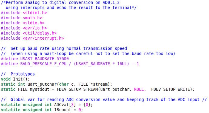
51 Example!
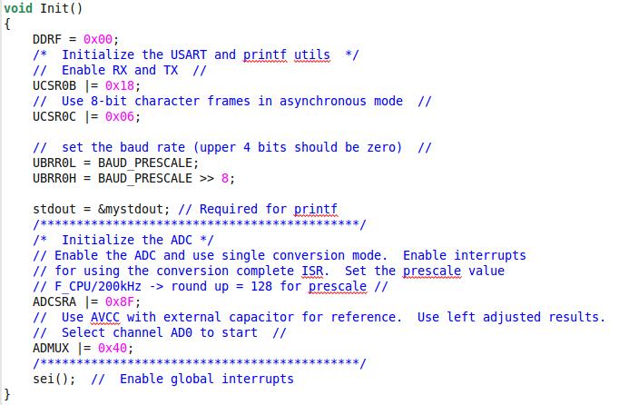
52 Example!
53 Example!
Fig. 1 Analog pins of Arduino Mega
 Laboratory 7 Analog signals processing An analog signals is variable voltage over time and is usually the output of a sensor that monitors the environment. Such a signal can be processed and interpreted
CPE 310L EMBEDDED SYSTEM DESIGN (CPE)
") CPE 310L EMBEDDED SYSTEM DESIGN (CPE) LABORATORY 8 ANALOG DIGITAL CONVERTER DEPARTMENT OF ELECTRICAL AND COMPUTER ENGINEERING UNIVERSITY OF NEVADA, LAS VEGAS GOAL The goal of this lab is to understand
CPE 310L EMBEDDED SYSTEM DESIGN (CPE) LABORATORY 8 ANALOG DIGITAL CONVERTER DEPARTMENT OF ELECTRICAL AND COMPUTER ENGINEERING UNIVERSITY OF NEVADA, LAS VEGAS GOAL The goal of this lab is to understand
Converters: Analogue to Digital
 Converters: Analogue to Digital Presented by: Dr. Walid Ghoneim References: Process Control Instrumentation Technology, Curtis Johnson Op Amps Design, Operation and Troubleshooting. David Terrell 1 - ADC
EECS 373 Design of Microprocessor-Based Systems
 EECS 373 Design of Microprocessor-Based Systems A day of Misc. Topics Mark Brehob University of Michigan Lecture 12: Finish up Analog and Digital converters Finish design rules Quick discussion of MMIO
Introduction to Mechatronics. Fall Instructor: Professor Charles Ume. Analog to Digital Converter
 ME6405 Introduction to Mechatronics Fall 2006 Instructor: Professor Charles Ume Analog to Digital Converter Analog and Digital Signals Analog signals have infinite states available mercury thermometer
Analog Input & Output
 EEL 4744C: Microprocessor Applications Lecture 10 Part 1 Analog Input & Output Dr. Tao Li 1 Read Assignment M&M: Chapter 11 Dr. Tao Li 2 To process continuous signals as functions of time Advantages free
Analog to Digital Converter. Last updated 7/27/18
 Analog to Digital Converter Last updated 7/27/18 Analog to Digital Conversion Most of the real world is analog temperature, pressure, voltage, current, To work with these values in a computer we must convert
Part 2 -- A digital thermometer or talk I2C to your atmel microcontroller
 Home Electronics Graphics, Film & Animation E-cards Other Linux stuff Photos Online-Shop Content: The new things The LCD display A little GUI How it works: Analog to digital conversion How it works: I2C
Data Converter Overview: DACs and ADCs. Dr. Paul Hasler and Dr. Philip Allen
 Data Converter Overview: DACs and ADCs Dr. Paul Hasler and Dr. Philip Allen The need for Data Converters ANALOG SIGNAL (Speech, Images, Sensors, Radar, etc.) PRE-PROCESSING (Filtering and analog to digital
Decade Counters Mod-5 counter: Decade Counter:
 Decade Counters We can design a decade counter using cascade of mod-5 and mod-2 counters. Mod-2 counter is just a single flip-flop with the two stable states as 0 and 1. Mod-5 counter: A typical mod-5
Data Conversion and Lab (17.368) Fall Lecture Outline
 Fall Lecture Outline") Data Conversion and Lab (17.368) Fall 2013 Lecture Outline Class # 11 November 14, 2013 Dohn Bowden 1 Today s Lecture Outline Administrative Detailed Technical Discussions Lab Microcontroller and Sensors
Data Conversion and Lab (17.368) Fall 2013 Lecture Outline Class # 11 November 14, 2013 Dohn Bowden 1 Today s Lecture Outline Administrative Detailed Technical Discussions Lab Microcontroller and Sensors
Section bit Analog-to-Digital Converter (ADC)
") Section 17. 10-bit Analog-to-Digital Converter (ADC) HIGHLIGHTS This section of the manual contains the following major topics: 17 17.1 Introduction...17-2 17.2 Control Registers...17-4 17.3 ADC Operation,
Section 17. 10-bit Analog-to-Digital Converter (ADC) HIGHLIGHTS This section of the manual contains the following major topics: 17 17.1 Introduction...17-2 17.2 Control Registers...17-4 17.3 ADC Operation,
Hello and welcome to this presentation of the STM32L4 Analog-to-Digital Converter block. It will cover the main features of this block, which is used
 Hello and welcome to this presentation of the STM32L4 Analog-to-Digital Converter block. It will cover the main features of this block, which is used to convert the external analog voltage-like sensor
Experiment # 4 Counters and Logic Analyzer
 EE20L - Introduction to Digital Circuits Experiment # 4. Synopsis: Experiment # 4 Counters and Logic Analyzer In this lab we will build an up-counter and a down-counter using 74LS76A - Flip Flops. The
MAHARASHTRA STATE BOARD OF TECHNICAL EDUCATION (Autonomous) (ISO/IEC Certified) WINTER 2018 EXAMINATION MODEL ANSWER
 (ISO/IEC Certified) WINTER 2018 EXAMINATION MODEL ANSWER") Important Instructions to examiners: 1) The answers should be examined by key words and not as word-to-word as given in themodel answer scheme. 2) The model answer and the answer written by candidate may
Important Instructions to examiners: 1) The answers should be examined by key words and not as word-to-word as given in themodel answer scheme. 2) The model answer and the answer written by candidate may
Converting between Analog and Digital Domains
 Converting between Analog and Digital Domains Chapter 6 Renesas Electronics America Inc. Advanced Embedded Systems using the RX63N Rev. 0.1 00000-A Topics Need Reference voltage Resolution Sample and Hold
Interfacing Analog to Digital Data Converters. A/D D/A Converter 1
 Interfacing Analog to Digital Data Converters A/D D/A Converter 1 In most of the cases, the PPI 8255 is used for interfacing the analog to digital converters with microprocessor. The analog to digital
Tutorial on Technical and Performance Benefits of AD719x Family
 The World Leader in High Performance Signal Processing Solutions Tutorial on Technical and Performance Benefits of AD719x Family AD7190, AD7191, AD7192, AD7193, AD7194, AD7195 This slide set focuses on
Analog-to-Digital Conversion (Part 2) Microcomputer Architecture and Interfacing Colorado School of Mines Professor William Hoff
 Microcomputer Architecture and Interfacing Colorado School of Mines Professor William Hoff") Analog-to-Digital Conversion (Part 2) Charge redistribution network Instead of a resistor ladder for the D/A converter, the microcontroller uses an-all capacitor system to generate the known voltages It
Analog-to-Digital Conversion (Part 2) Charge redistribution network Instead of a resistor ladder for the D/A converter, the microcontroller uses an-all capacitor system to generate the known voltages It
SUBSYSTEMS FOR DATA ACQUISITION #39. Analog-to-Digital Converter (ADC) Function Card
 Function Card") SUBSYSTEMS FOR DATA ACQUISITION #39 Analog-to-Digital Converter (ADC) Function Card Project Scope Design an ADC function card for an IEEE 488 interface box built by Dr. Robert Kolbas. ADC card will add
SUBSYSTEMS FOR DATA ACQUISITION #39 Analog-to-Digital Converter (ADC) Function Card Project Scope Design an ADC function card for an IEEE 488 interface box built by Dr. Robert Kolbas. ADC card will add
PHYS 3322 Modern Laboratory Methods I Digital Devices
 PHYS 3322 Modern Laboratory Methods I Digital Devices Purpose This experiment will introduce you to the basic operating principles of digital electronic devices. Background These circuits are called digital
WINTER 15 EXAMINATION Model Answer
 Important Instructions to examiners: 1) The answers should be examined by key words and not as word-to-word as given in the model answer scheme. 2) The model answer and the answer written by candidate
PESIT Bangalore South Campus
 SOLUTIONS TO INTERNAL ASSESSMENT TEST 3 Date : 8/11/2016 Max Marks: 40 Subject & Code : Analog and Digital Electronics (15CS32) Section: III A and B Name of faculty: Deepti.C Time : 11:30 am-1:00 pm Note:
Complete 10-Bit, 25 MHz CCD Signal Processor AD9943
 a FEATURES 25 MSPS Correlated Double Sampler (CDS) 6 db to 40 db 10-Bit Variable Gain Amplifier (VGA) Low Noise Optical Black Clamp Circuit Preblanking Function 10-Bit, 25 MSPS A/D Converter No Missing
NI-DAQmx Device Considerations
 NI-DAQmx Device Considerations January 2008, 370738M-01 This help file contains information specific to analog output (AO) Series devices, C Series, B Series, E Series devices, digital I/O (DIO) devices,
Complete 12-Bit 40 MHz CCD Signal Processor AD9945
 Complete 12-Bit 40 MHz CCD Signal Processor AD9945 FEATURES 40 MSPS Correlated Double Sampler (CDS) 6 db to 40 db 10-Bit Variable Gain Amplifier (VGA) Low Noise Optical Black Clamp Circuit Preblanking
Complete 10-Bit/12-Bit, 25 MHz CCD Signal Processor AD9943/AD9944
 a FEATURES 25 MSPS Correlated Double Sampler (CDS) 6 db to 40 db 10-Bit Variable Gain Amplifier (VGA) Low Noise Optical Black Clamp Circuit Preblanking Function 10-Bit (AD9943), 12-Bit (AD9944), 25 MSPS
Synthesized Clock Generator
 Synthesized Clock Generator CG635 DC to 2.05 GHz low-jitter clock generator Clocks from DC to 2.05 GHz Random jitter
ADC Peripheral in Microcontrollers. Petr Cesak, Jan Fischer, Jaroslav Roztocil
 ADC Peripheral in s Petr Cesak, Jan Fischer, Jaroslav Roztocil Czech Technical University in Prague, Faculty of Electrical Engineering Technicka 2, CZ-16627 Prague 6, Czech Republic Phone: +420-224 352
Complete 14-Bit, 56 MSPS Imaging Signal Processor AD9941
 Complete 14-Bit, 56 MSPS Imaging Signal Processor AD9941 FEATURES Differential sensor input with 1 V p-p input range 0 db/6 db variable gain amplifier (VGA) Low noise optical black clamp circuit 14-bit,
Tutorial Introduction
 Tutorial Introduction PURPOSE - To explain how to configure and use the in common applications OBJECTIVES: - Identify the steps to set up and configure the. - Identify techniques for maximizing the accuracy
Specifications for Thermopilearrays HTPA8x8, HTPA16x16 and HTPA32x31 Rev.6: Fg
 Principal Schematic for HTPA16x16: - 1 - Pin Assignment in TO8 for 8x8: Connect all reference voltages via 100 nf capacitors to VSS. Pin Assignment 8x8 Pin Name Description Type 1 VSS Negative power supply
Complete 14-Bit 30 MSPS CCD Signal Processor AD9824
 a FEATURES 14-Bit 30 MSPS A/D Converter 30 MSPS Correlated Double Sampler (CDS) 4 db 6 db 6-Bit Pixel Gain Amplifier (PxGA ) 2 db to 36 db 10-Bit Variable Gain Amplifier (VGA) Low Noise Clamp Circuits
Analog-to-Digital Converter
 5 5.1 Objectives: The TM4C is equipped with an analog-to-digital (ATD) conversion system that samples an analog (continuous) signal at regular intervals and then converts each of these analog samples into
VIRTUAL INSTRUMENTATION
 VIRTUAL INSTRUMENTATION Virtual instrument an equimplent that allows accomplishment of measurements using the computer. It looks like a real instrument, but its operation and functionality is essentially
WINTER 14 EXAMINATION
 Subject Code: 17320 WINTER 14 EXAMINATION Model Answer Important Instructions to examiners: 1) The answers should be examined by key words and not as word-to-word as given in the model answer scheme. 2)
Note 5. Digital Electronic Devices
 Note 5 Digital Electronic Devices Department of Mechanical Engineering, University Of Saskatchewan, 57 Campus Drive, Saskatoon, SK S7N 5A9, Canada 1 1. Binary and Hexadecimal Numbers Digital systems perform
Chapter 11 Sections 1 3 Dr. Iyad Jafar
 Data Acquisition and Manipulation Chapter 11 Sections 1 3 Dr. Iyad Jafar Outline Analog and Digital Quantities The Analog to Digital Converter Features of Analog to Digital Converter The Data Acquisition
Digital Fundamentals. Introduction to Digital Signal Processing
 Digital Fundamentals Introduction to Digital Signal Processing 1 Objectives List the essential elements in a digital signal processing system Explain how analog signals are converted to digital form Discuss
AN919: Using the EFM8LB1 ADC
 This application note shows general operation and usage of the EFM8LB1's and EFM8BB3's ADC. In addition, this document describes the advanced features of the ADC including Window Compare, Autoscan mode,
Synthesis Technology E102 Quad Temporal Shifter User Guide Version 1.0. Dec
 Synthesis Technology E102 Quad Temporal Shifter User Guide Version 1.0 Dec. 2014 www.synthtech.com/euro/e102 OVERVIEW The Synthesis Technology E102 is a digital implementation of the classic Analog Shift
PCI-DAS6034, PCI-DAS6035, and PCI-DAS6036
 PCI-DAS6034, PCI-DAS6035, and PCI-DAS6036 Specifications Document Revision 1.2, February, 2010 Copyright 2010, Measurement Computing Corporation Typical for 25 C unless otherwise specified. Specifications
Analog-to-Digital Conversion
 ADC-DAC ผศ.ดร. ส ร นทร ก ตต ธรก ล และ อ.สรย ทธ กลมกล อม ภาคว ชาว ศวกรรมคอมพ วเตอร คณะว ศวกรรมศาสตร สถาบ นเทคโนโลย พระจอมเกล าเจ าค ณทหารลาดกระบ ง Computer Interfacing, KMITL ADC-DAC 1 Analog-to-Digital
Sources of Error in Time Interval Measurements
 Sources of Error in Time Interval Measurements Application Note Some timer/counters available today offer resolution of below one nanosecond in their time interval measurements. Of course, high resolution
INF4420 Project Spring Successive Approximation Register (SAR) Analog-to-Digital Converter (ADC)
 Analog-to-Digital Converter (ADC)") INF4420 Project Spring 2011 Successive Approximation Register (SAR) Analog-to-Digital Converter (ADC) 1. Introduction Data converters are one of the fundamental building blocks in integrated circuit design.
INF4420 Project Spring 2011 Successive Approximation Register (SAR) Analog-to-Digital Converter (ADC) 1. Introduction Data converters are one of the fundamental building blocks in integrated circuit design.
Chapter 29 Analog Digital Converter (ADC)
") Chapter 29 Analog Digital Converter (ADC) 29.1 Introduction The analog-to-digital (ADC) converter block consists of two separate analog to digital converters, each with four analog inputs and their own
Chapter 29 Analog Digital Converter (ADC) 29.1 Introduction The analog-to-digital (ADC) converter block consists of two separate analog to digital converters, each with four analog inputs and their own
B I O E N / Biological Signals & Data Acquisition
 B I O E N 4 6 8 / 5 6 8 Lectures 1-2 Analog to Conversion Binary numbers Biological Signals & Data Acquisition In order to extract the information that may be crucial to understand a particular biological
Copyright. Robert Alexander Fontaine
 Copyright by Robert Alexander Fontaine 2013 The Report Committee for Robert Alexander Fontaine Certifies that this is the approved version of the following report: Investigation of 10-Bit SAR ADC Using
Introduction to Embedded Microcomputer Systems Lecture Discrete digital signal. Continuous analog signal
 Introduction to Embedded Microcomputer Systems Lecture 22.1 Recap Output compare interrupts Metrowerks Codewarrior Overview to Convertor Transducer: mechanical, electrical Using output compare interrupts
High Performance TFT LCD Driver ICs for Large-Size Displays
 Name: Eugenie Ip Title: Technical Marketing Engineer Company: Solomon Systech Limited www.solomon-systech.com The TFT LCD market has rapidly evolved in the last decade, enabling the occurrence of large
3 V/5 V, 450 μa 16-Bit, Sigma-Delta ADC AD7715
 3 V/5 V, 450 μa 16-Bit, Sigma-Delta ADC AD7715 FEATURES Charge-balancing ADC 16-bits no missing codes 0.0015% nonlinearity Programmable gain front end Gains of 1, 2, 32 and 128 Differential input capability
Politecnico di Torino HIGH SPEED AND HIGH PRECISION ANALOG TO DIGITAL CONVERTER. Professor : Del Corso Mahshid Hooshmand ID Student Number:
 Politecnico di Torino HIGH SPEED AND HIGH PRECISION ANALOG TO DIGITAL CONVERTER Professor : Del Corso Mahshid Hooshmand ID Student Number: 181517 13/06/2013 Introduction Overview.....2 Applications of
AD16-64(LPCI)LA. Non-isolated high precision analog input board for Low Profile PCI AD16-64(LPCI)LA 1. Ver.1.01
LA. Non-isolated high precision analog input board for Low Profile PCI AD16-64(LPCI)LA 1. Ver.1.01") Non-isolated high precision analog board for Low Profile PCI AD16-64(LPCI)LA * Specifications, color and design of the products are subject to change without notice. This product is a PCI bus compatible
Non-isolated high precision analog board for Low Profile PCI AD16-64(LPCI)LA * Specifications, color and design of the products are subject to change without notice. This product is a PCI bus compatible
Experiment 2: Sampling and Quantization
 ECE431, Experiment 2, 2016 Communications Lab, University of Toronto Experiment 2: Sampling and Quantization Bruno Korst - bkf@comm.utoronto.ca Abstract In this experiment, you will see the effects caused
nc... Freescale Semiconductor, I
 Application Note Rev. 0, 2/2003 Interfacing to the HCS12 ATD Module by Martyn Gallop, Application Engineering, Freescale, East Kilbride Introduction Many of the HCS12 family of 16-bit microcontrollers
International Islamic University Chittagong (IIUC) Department of Electrical and Electronic Engineering (EEE)
 Department of Electrical and Electronic Engineering (EEE)") International Islamic University Chittagong (IIUC) Department of Electrical and Electronic Engineering (EEE) Course Code: EEE 3518 Course Title: Embedded System Sessional EXPERIMENT NO. 8 Name of the Experiment:
International Islamic University Chittagong (IIUC) Department of Electrical and Electronic Engineering (EEE) Course Code: EEE 3518 Course Title: Embedded System Sessional EXPERIMENT NO. 8 Name of the Experiment:
Complete 12-Bit 30 MSPS CCD Signal Processor AD9845B
 Complete 12-Bit 30 MSPS CCD Signal Processor AD9845B FEATURES Pin Compatible with AD9845A Designs 12-Bit 30 MSPS A/D Converter 30 MSPS Correlated Double Sampler (CDS) 4 db 6 db 6-Bit Pixel Gain Amplifier
MAHARASHTRA STATE BOARD OF TECHNICAL EDUCATION (Autonomous)
") Subject Code: 17320 Model Answer Page 1 of 32 Important Instructions to examiners: 1) The answers should be examined by key words and not as word-to-word as given in the Model answer scheme. 2) The model
Subject Code: 17320 Model Answer Page 1 of 32 Important Instructions to examiners: 1) The answers should be examined by key words and not as word-to-word as given in the Model answer scheme. 2) The model
Logic Gates, Timers, Flip-Flops & Counters. Subhasish Chandra Assistant Professor Department of Physics Institute of Forensic Science, Nagpur
 Logic Gates, Timers, Flip-Flops & Counters Subhasish Chandra Assistant Professor Department of Physics Institute of Forensic Science, Nagpur Logic Gates Transistor NOT Gate Let I C be the collector current.
TV Synchronism Generation with PIC Microcontroller
 TV Synchronism Generation with PIC Microcontroller With the widespread conversion of the TV transmission and coding standards, from the early analog (NTSC, PAL, SECAM) systems to the modern digital formats
ASNT_PRBS20B_1 18Gbps PRBS7/15 Generator Featuring Jitter Insertion, Selectable Sync, and Output Amplitude Control
 ASNT_PRBS20B_1 18Gbps PRBS7/15 Generator Featuring Jitter Insertion, Selectable Sync, and Output Amplitude Control Broadband frequency range from 20Mbps 18.0Gbps Minimal insertion jitter Fast rise and
ES /2 digit with LCD
 Features Max. ±19,999 counts QFP-44L and DIP-40L package Input full scale range: 200mV or 2V Built-in multiplexed LCD display driver Underrange/Overrange outputs 10µV resolution on 200mV scale Display
3 V/5 V, CMOS, 500 A Signal Conditioning ADC AD7714
 a FEATURES Charge Balancing ADC 24 Bits No Missing Codes 0.0015% Nonlinearity Five-Channel Programmable Gain Front End Gains from 1 to 128 Can Be Configured as Three Fully Differential Inputs or Five Pseudo-Differential
GALILEO Timing Receiver
 GALILEO Timing Receiver The Space Technology GALILEO Timing Receiver is a triple carrier single channel high tracking performances Navigation receiver, specialized for Time and Frequency transfer application.
2 The Essentials of Binary Arithmetic
 ENGG1000: Engineering esign and Innovation Stream: School of EE&T Lecture Notes Chapter 5: igital Circuits A/Prof avid Taubman April5,2007 1 Introduction This chapter can be read at any time after Chapter
Digital Correction for Multibit D/A Converters
 Digital Correction for Multibit D/A Converters José L. Ceballos 1, Jesper Steensgaard 2 and Gabor C. Temes 1 1 Dept. of Electrical Engineering and Computer Science, Oregon State University, Corvallis,
Digital Signal. Continuous. Continuous. amplitude. amplitude. Discrete-time Signal. Analog Signal. Discrete. Continuous. time. time.
 Discrete amplitude Continuous amplitude Continuous amplitude Digital Signal Analog Signal Discrete-time Signal Continuous time Discrete time Digital Signal Discrete time 1 Digital Signal contd. Analog
Fast Quadrature Decode TPU Function (FQD)
") PROGRAMMING NOTE Order this document by TPUPN02/D Fast Quadrature Decode TPU Function (FQD) by Jeff Wright 1 Functional Overview The fast quadrature decode function is a TPU input function that uses two
PROGRAMMING NOTE Order this document by TPUPN02/D Fast Quadrature Decode TPU Function (FQD) by Jeff Wright 1 Functional Overview The fast quadrature decode function is a TPU input function that uses two
GHz Sampling Design Challenge
 GHz Sampling Design Challenge 1 National Semiconductor Ghz Ultra High Speed ADCs Target Applications Test & Measurement Communications Transceivers Ranging Applications (Lidar/Radar) Set-top box direct
ADC0804C, ADC BIT ANALOG-TO-DIGITAL CONVERTERS WITH DIFFERENTIAL INPUTS
 8-Bit esolution atiometric Conversion 100-µs Conversion Time 135-ns Access Time No Zero Adjust equirement On-Chip Clock Generator Single 5-V Power Supply Operates With Microprocessor or as Stand-Alone
The Successive Approximation Converter Concept - 8 Bit, 5 Volt Example
 Successive Approximation Converter A successive approximation converter provides a fast conversion of a momentary value of the input signal. It works by first comparing the input with a voltage which is
Hello and welcome to this training module for the STM32L4 Liquid Crystal Display (LCD) controller. This controller can be used in a wide range of
 controller. This controller can be used in a wide range of") Hello and welcome to this training module for the STM32L4 Liquid Crystal Display (LCD) controller. This controller can be used in a wide range of applications such as home appliances, medical, automotive,
Hello and welcome to this training module for the STM32L4 Liquid Crystal Display (LCD) controller. This controller can be used in a wide range of applications such as home appliances, medical, automotive,
Complete 12-Bit 40 MHz CCD Signal Processor AD9945
 Complete 12-Bit 40 MHz CCD Signal Processor AD9945 FEATURES 40 MSPS Correlated Double Sampler (CDS) 6 db to 40 db 10-Bit Variable Gain Amplifier (VGA) Low Noise Optical Black Clamp Circuit Preblanking
Generation and Measurement of Burst Digital Audio Signals with Audio Analyzer UPD
 Generation and Measurement of Burst Digital Audio Signals with Audio Analyzer UPD Application Note GA8_0L Klaus Schiffner, Tilman Betz, 7/97 Subject to change Product: Audio Analyzer UPD . Introduction
Analogue Versus Digital [5 M]
![Analogue Versus Digital [5 M]](/thumbs/93/111640168.jpg "Analogue Versus Digital [5 M]") Q.1 a. Analogue Versus Digital [5 M] There are two basic ways of representing the numerical values of the various physical quantities with which we constantly deal in our day-to-day lives. One of the ways,
Q.1 a. Analogue Versus Digital [5 M] There are two basic ways of representing the numerical values of the various physical quantities with which we constantly deal in our day-to-day lives. One of the ways,
AI-1616L-LPE. Features. High-precision Analog input board (Low Profile size) for PCI Express AI-1616L-LPE 1. Ver.1.02 Ver.1.01
 for PCI Express AI-1616L-LPE 1. Ver.1.02 Ver.1.01") High-precision Analog input board (Low Profile size) for PCI Express AI-1616L-LPE This product is a multi-function, PCI Express bus-compliant interface board that incorporates high-precision 16-bit analog
High-precision Analog input board (Low Profile size) for PCI Express AI-1616L-LPE This product is a multi-function, PCI Express bus-compliant interface board that incorporates high-precision 16-bit analog
NanoGiant Oscilloscope/Function-Generator Program. Getting Started
 Getting Started Page 1 of 17 NanoGiant Oscilloscope/Function-Generator Program Getting Started This NanoGiant Oscilloscope program gives you a small impression of the capabilities of the NanoGiant multi-purpose
ELCT706 MicroLab Session #3 7-segment LEDs and Analog to Digital Conversion. Eng. Salma Hesham
 ELCT706 MicroLab Session #3 7-segment LEDs and Analog to Digital Conversion 7-Segment LED Display g f com a b e d com c P 7-Segment LED Display Common Cathode - Com Pin = Gnd - Active high inputs - Example
SignalTap Plus System Analyzer
 SignalTap Plus System Analyzer June 2000, ver. 1 Data Sheet Features Simultaneous internal programmable logic device (PLD) and external (board-level) logic analysis 32-channel external logic analyzer 166
B. Sc. III Semester (Electronics) - ( ) Digital Electronics-II) BE-301 MODEL ANSWER (AS-2791)
 - ( ) Digital Electronics-II) BE-301 MODEL ANSWER (AS-2791)") B. Sc. III Semester (Electronics) - (2013-14) Digital Electronics-II) BE-301 MODEL ANSWER (AS-2791) Section-[A] i. (B) ii. (A) iii. (D) iv. (C) v. (C) vi. (C) vii. (D) viii. (B) Ans-(ix): In JK flip flop
B. Sc. III Semester (Electronics) - (2013-14) Digital Electronics-II) BE-301 MODEL ANSWER (AS-2791) Section-[A] i. (B) ii. (A) iii. (D) iv. (C) v. (C) vi. (C) vii. (D) viii. (B) Ans-(ix): In JK flip flop
Low Power, 16-Bit Buffered Sigma-Delta ADC AD7790
 Low Power, 16-Bit Buffered Sigma-Delta ADC AD7790 FEATURES Power Supply: 2.5 V to 5.25 V operation Normal: 75 µa maximum Power-down: 1 µa maximum RMS noise: 1.1 µv at 9.5 Hz update rate 16-bit p-p resolution
LX3V-4AD User manual Website: Technical Support: Skype: Phone: QQ Group: Technical forum:
 User manual Website: http://www.we-con.com.cn/en Technical Support: support@we-con.com.cn Skype: fcwkkj Phone: 86-591-87868869 QQ Group: 465230233 Technical forum: http://wecon.freeforums.net/ 1. Introduction
MAHARASHTRA STATE BOARD OF TECHNICAL EDUCATION (Autonomous) (ISO/IEC Certified)
 (ISO/IEC Certified)") Important Instructions to examiners: 1) The answers should be examined by key words and not as word-to-word as given in the model answer scheme. 2) The model answer and the answer written by candidate
Important Instructions to examiners: 1) The answers should be examined by key words and not as word-to-word as given in the model answer scheme. 2) The model answer and the answer written by candidate
BASCOM-TV. TV Code Features: ICs supported: BASCOM versions:
 BASCOM-TV With this software module you can generate output directly to a TV - via an RGB SCART connection - from BASCOM (AVR), using a just few resistors and a 20 MHz crystal. Write your program with
Published in A R DIGITECH
 Design of propeller clock by using 8051 Microcontroller Ahmed H. Al-Saadi*1 *1 (B.Sc. of Computer Engineering in Al Hussein University College of Engineering, Iraq) ah9@outlook.com*1 Abstract The propeller
Chapter 4. Logic Design
 Chapter 4 Logic Design 4.1 Introduction. In previous Chapter we studied gates and combinational circuits, which made by gates (AND, OR, NOT etc.). That can be represented by circuit diagram, truth table
3 V/5 V, CMOS, 500 A Signal Conditioning ADC AD7714
 a FEATURES Charge Balancing ADC 24 Bits No Missing Codes 0.0015% Nonlinearity Five-Channel Programmable Gain Front End Gains from 1 to 128 Can Be Configured as Three Fully Differential Inputs or Five Pseudo-Differential
DT9837 Series. High Performance, USB Powered Modules for Sound & Vibration Analysis. Key Features:
 DT9837 Series High Performance, Powered Modules for Sound & Vibration Analysis The DT9837 Series high accuracy dynamic signal acquisition modules are ideal for portable noise, vibration, and acoustic measurements.
DT8837. High Performance Ethernet Instrument Module for Sound & Vibration. Overview. Key Features
 DT8837 High Performance Ethernet Instrument Module for Sound & Vibration Overview The DT8837 is a high-accuracy, multi-channel module that is ideal for sound and vibration measurements. All the I/O channels
PICOSECOND TIMING USING FAST ANALOG SAMPLING
 PICOSECOND TIMING USING FAST ANALOG SAMPLING H. Frisch, J-F Genat, F. Tang, EFI Chicago, Tuesday 6 th Nov 2007 INTRODUCTION In the context of picosecond timing, analog detector pulse sampling in the 10
Artisan Technology Group is your source for quality new and certified-used/pre-owned equipment
 Artisan Technology Group is your source for quality new and certified-used/pre-owned equipment FAST SHIPPING AND DELIVERY TENS OF THOUSANDS OF IN-STOCK ITEMS EQUIPMENT DEMOS HUNDREDS OF MANUFACTURERS SUPPORTED
Department of Communication Engineering Digital Communication Systems Lab CME 313-Lab
 German Jordanian University Department of Communication Engineering Digital Communication Systems Lab CME 313-Lab Experiment 3 Pulse Code Modulation Eng. Anas Alashqar Dr. Ala' Khalifeh 1 Experiment 2Experiment
Integrated Circuit for Musical Instrument Tuners
 Document History Release Date Purpose 8 March 2006 Initial prototype 27 April 2006 Add information on clip indication, MIDI enable, 20MHz operation, crystal oscillator and anti-alias filter. 8 May 2006
IV 251. Signal Converter SSI Analogue and SSI Serial. Operating Instructions. control motion interface
 control motion interface IV 251 Signal Converter SSI Analogue and SSI Serial Suitable for operation with all sensors and encoders using SSI interface Scalable analogue outputs +/- 10 volts, 0-20 ma and
110 MHz 256-Word Color Palette 15-, 16-, and 24-Bit True Color Power-Down RAMDAC
 110 MHz 256-Word Color Palette 15-, 16-, and 24-Bit True Color Power-Down RAMDAC Designed specifically for high-performance color graphics, the RAM- DAC supports three true-color modes: 15-bit (5:5:5,
DT9857E. Key Features: Dynamic Signal Analyzer for Sound and Vibration Analysis Expandable to 64 Channels
 DT9857E Dynamic Signal Analyzer for Sound and Vibration Analysis Expandable to 64 Channels The DT9857E is a high accuracy dynamic signal acquisition module for noise, vibration, and acoustic measurements
Major Differences Between the DT9847 Series Modules
 DT9847 Series Dynamic Signal Analyzer for USB With Low THD and Wide Dynamic Range The DT9847 Series are high-accuracy, dynamic signal acquisition modules designed for sound and vibration applications.
DIGITAL ELECTRONICS: LOGIC AND CLOCKS
 DIGITL ELECTRONICS: LOGIC ND CLOCKS L 6 INTRO: INTRODUCTION TO DISCRETE DIGITL LOGIC, MEMORY, ND CLOCKS GOLS In this experiment, we will learn about the most basic elements of digital electronics, from
FRQM-2 Frequency Counter & RF Multimeter
 FRQM-2 Frequency Counter & RF Multimeter Usage Instructions Firmware v2.09 Copyright 2007-2011 by ASPiSYS Ltd. Distributed by: ASPiSYS Ltd. P.O.Box 14386, Athens 11510 (http://www.aspisys.com) Tel. (+30)
Notes on Digital Circuits
 PHYS 331: Junior Physics Laboratory I Notes on Digital Circuits Digital circuits are collections of devices that perform logical operations on two logical states, represented by voltage levels. Standard