Infra-Red Vortex-Evaporator. User manual Version 3.4
|
|
|
- Nickolas Cole
- 5 years ago
- Views:
Transcription


1 CombiDancer Infra-Red Vortex-Evaporator User manual Version 3.4 Seestrasse 204a, CH-8806 Baech / SZ, Switzerland Tel , Fax mail@hettich-ag.ch, Internet:
2 Table of contents 1. Operating principle, installation and first steps Operating principle Safety instructions Package contents The CombiDancer Infrared Vortex Evaporator Device construction CombiDancer control panel Vacuum chamber Sample racks PoleStar cold trap Vacuum pump Installation of the CombiDancer Connecting diaphragm pump and cold trap Activation of remote operation for the Vacuubrand 14 PC2003/2004 VARIO diaphragm pump Setting up the PoleStar cold trap The CombiDancer Program Device specifications Working with the CombiDancer Control panel Operation parameter input Display Display of the current sample number Cold trap status Pump status Pump operation modes Statuses of the valves and the key-operated switch, of the PC-access and the CombiDancer Multifunction button assignment Creating a program Time Menu Vortex Menu Temperature Menu Pump Menu Program Menu Accessing the Program Menu Storing and recalling a SINGLE Program The Multi Menu Recalling an existing program (MULTI) Creating and editing a Multi Program Storing a Multi Program Deleting a Multi Program Set value overview (VAL button) 38 2
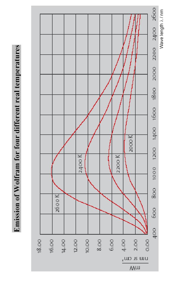
3 2.4.7 Main Setting Menu Temperature Submenu External Units Submenu Program Setting Submenu PC Access Submenu Configuration Submenu 44 Appendix A : ERROR-Codes 45/46 Appendix B : Spare parts list (electrical) 47 Appendix C : Spare parts list (mechanical) 48 Appendix D : Spare parts list (exchange) 48 Appendix E : Infrared spectrum 49 3
4 1. Operating principle, installation and first steps 1.1 Operating principle Thank you for choosing the CombiDancer Infrared Vortex Evaporator; this device has been designed to suit the most demanding requirements and to ensure the highest flexibility for the evaporation of solvents using various types of sample tubes, microtiter or deepwell plates. The operating principle is a combination of heating, vortex and vacuum as a function of time. These parameters can be combined into a maximum of 99 single-level programs, i.e. 26 multi-level programs, allowing complex solvent mixtures to evaporate quickly and gently. The CombiDancer can accommodate up to 4 deepwell plates or microtiter plates. Special racks can also accommodate HPLC-vials or other larger containers, such as Falcon tubes for instance. The vacuum can be adjusted using a diaphragm pump or a rotary vane pump. Infrared lamps located in the lid heat the samples. An independent compartment heater prevents the condensation of solvents with high boiling point in the vacuum chamber. The actual temperature can be measured directly in the sample or in the rack by means of a PTFE-coated temperature sensor. All parameters can be programmed and controlled separately. There are no rotating parts in the CombiDancer. Vortex of the samples is achieved by means of a magnetic drive. No balancing of the samples required. Picture 1.1 shows the CombiDancer with PoleStar cold trap and Vacuubrand PC-2003 VARIO diaphragm pump. 1.2 Safety instructions The CombiDancer Infrared Vortex Evaporator is a state of the art, reliable product; however, it may lead to hazards for the user or a third party if it is not used by trained personnel, if used improperly, or if the user does not observe instructions. Operating instructions of the CombiDancer must be read and observed before the device is put into operation. Besides operating instructions and regulations regarding prevention of accidents, the universally recognized technical standards for safe working conditions have to be observed at all times. In addition to the operating instructions, the current national regulations concerning prevention of accidents and environmental care also have to be observed. 4

5 Picture 1.1: CombiDancer with Vacuubrand PC-2003 VARIO diaphragm pump and the PoleStar cold trap Only connect devices to a grounded electrical outlet, using power cords corresponding to the instructions. Never use damaged cables. Damaged or insufficient grounding involves danger of life. Attention must be paid to the instructions concerning AC power and power consumption. When the CombiDancer is transferred from a cold place to the laboratory, condensation may appear on the device. In such a case, allow it to acclimatize before operating. Attention must be paid to allowable ambient operating temperature and to air supply, especially during installation of the device. A vacuum is generated by the vacuum pump during solvent evaporation. Observe safety rules to generate and measure vacuum. Operating instructions of the utilized vacuum pump also have to be observed. Only qualified personnel are authorized to service this equipment. Use only genuine parts and accessories. The use of components from another manufacturer may affect the functionality i.e. the safety of the device and its electromagnetic compatibility. Do not place any solvent container or any objects on the CombiDancer. 5
6 The coolant circuit of the PoleStar cold trap is maintenance-free. A qualified refrigeration specialist should be the only person authorized to remove errors if any should appear. 1.3 Package contents Now please take the CombiDancer and its accessories out of the box. The package contents: 1x CombiDancer Infrared Vortex Evaporator 1x standard shaker plate CD.Z900 1x power cord 1x 9-pin serial cable RS-232 1:1 male / female 2x lock keys 1x emergency key (for opening the lid) 1x operation manual Should one of the above listed items be missing, please contact the manufacturer or your reseller. 1.4 The CombiDancer Infrared Vortex Evaporator Device construction Picture 1.2 shows the front view of the CombiDancer. Picture 1.2: Front view of the CombiDancer Vacuum chamber lid On/Off switch vacuum chamber light Control panel Lock switch Observation window 6


7 Shows the lid of the vacuum chamber that opens by sliding to the side, thus allowing to work with laboratory robots. All relevant parameters for operating the CombiDancer can be managed and programmed via the control panel. See section 1.6 for more details concerning the control panel. The observation window allows to see the samples even during the evaporation process. The vacuum chamber light can be switched on and off using the corresponding switch. Different positions of the key lock allow to access different user levels, which are then displayed on the screen. For more details see section Picture 1.3 shows the back of the CombiDancer. The power cord is plugged into socket. Switch allows to turn the CombiDancer on and off. Picture 1.3: CombiDancer back view Power cord socket On/Off switch Louver Serial ports Cable conduit attached to CombiDancer lid Inert gas hose adaptor Cold trap / vacuum pump DN25 connector An electrical fan is mounted behind the louver. Serial ports allow to control a PC-2003/2004 diaphragm pump, PoleStar cold trap or to connect a PC to check up the device or to update its firmware. An alarm system can also be connected (see also picture 1.4). A cable conduit is attached to the lid of the device. A hose (6 mm in diameter) can be plugged into the adaptor for delicate samples in the CombiDancer to be flushed with inert gas. Vacuum pump and PoleStar cold trap are connected through the connectors. Picture 1.4: Serial ports of the CombiDancer AL = Alarm (potentially free Relay contacts) VP = Vacuubrand PC-2003/2004 VARIO diaphragm pump port CT = PoleStar cold trap port PC = PC port (RS-232) 7
8 1.4.2 CombiDancer control panel The control panel of the CombiDancer is shown in picture 1.5 Picture1.5: Control panel LCD-display (240 x 128 signs) Input buttons Rotary knob Function buttons 7-Segment LED displays The status of the device is displayed on display. This display also enables the operating parameter input. Input buttons are located along the left and right edges of the display. Symbols corresponding to the function of each button are displayed next to them along the left and right edges of the screen. These buttons are used to input and to check the operating parameters. The rotary knob is used for the input of alphanumerical parameters. There are three buttons on the right hand side of the control panel. The CombiDancer is started by pressing the [START] button and stopped by pressing the [STOP] button. Pressing the lower button will open the lid of the CombiDancer, which will slide to the left. There are three seven-segment displays on the left hand side of the control panel, which indicate the current parameters while operating the CombiDancer: - The upper segment display indicates elapsed time since starting the program and can also display error messages (Error). - The segment display in the middle indicates actual vortex speed. In the case of an operation error, the cause is indicated by an error code, e.g. the message ERROR30 indicates that the vacuum pump is not connected. See the table listing all ERROR-codes in appendix A of the user manual. - The lower segment display indicates the actual temperature measured by the temperature sensor (T1), which can be mounted in the sample rack. Optionally, the temperature of the compartment heater (T2) and the temperature of the optional heated base plate (T3) can also be displayed, simply by pressing a second or a third time on the lower button left to the status display. See section 2 for detailed description of input parameters. 8

9 1.4.3 Vacuum chamber Press the lower function button of the control panel to open the lid of the CombiDancer. The vacuum chamber can then be accessed. Picture 1.6 shows the open vacuum chamber. Picture 1.6: Vacuum chamber insight Holes for shaker plate PT-100 Temperature sensor (PTFE) Electrical connector for heated base plate There are four circular holes in the bottom of the vacuum chamber to accommodate the shaker plate with the rack. Temperature of the samples i.e. temperature of the racks can be measured by means of the temperature sensor. When a heated base plate (Option) is utilized, its cable can be plugged into the socket in the bottom of the vacuum chamber. Rack construction is described in section

 Sample racks can also be customized to fit your specific containers or container combination. Picture 1.")
10 1.4.4 Sample racks There are various racks that can be chosen to work with the CombiDancer. All racks have the same basis plate, on which different stands for the sample containers can be mounted. Picture 1.7 shows the basis plate. Sample racks are made out of anodize aluminum and exist for almost all common sample containers. They can accommodate up to 4 deep well plates. Perfect device functionality can only be guarantied when using original racks. Picture 1.7: Shaker plate with magnet feet and FEP o-rings (upside down view) Sample racks can also be customized to fit your specific containers or container combination. Picture 1.8 shows an overview about several standard and customized racks Picture 1.8: Different racks for deepwell plates, 50ml Falcon tubes, special glass vials and a universal rack. 10

11 Picture 1.9: shows a rack for Falcon tubes and a connected heated base plate (1). The temperature sensor can also be seen on the picture, mounted in a special opening on the rack, to record sample temperature. The temperature sensor can of course be placed in a reference container. Picture 1.9: Rack for Falcon tubes with connected heated base plate and temperature probe placed in the rack. 11


12 1.4.5 PoleStar Cold Trap Picture 1.10 shows the PoleStar Cold Trap from the front. It has a three-liter capacity. Power switch turns the unit on or off. Press the defrost switch to defrost frozen solvents. The window allows to see the cooling coil on which the solvent condensates and freezes. The temperature display indicates the actual temperature in the cold trap. Tubes connected to the CombiDancer and the vacuum pump also appear in this picture. You can also see the stopcock used for draining condensed solvent. Picture 1.10: PoleStar Cold Trap (front view) Temperature display Tube connected to the CombiDancer Defrost mode switch Tube connected to the vacuum pump Cold trap window Drain stopcock Picture 1.11: PoleStar Cold Trap (back view) Power switch Power cord socket outlet (to vacuum pump PC-2003/2004) Power cord socket inlet Serial port to CombiDancer (option for robotic use only) 12
13 1.4.6 Vacuum pump The CombiDancer works in combination with diaphragm pumps. Vacuubrand PC-2003/2004 VARIO diaphragm pump can be directly controlled via the control panel of the CombiDancer. NOTE: Vacuubrand PC-2003 VARIO diaphragm pump produces a maximum vacuum of 0,6 mbar. This is sufficient even to evaporate highboiling point solvents. Rotary vane pumps can also be used as stand alone units to produce vacuum. 1.5 Installation of the CombiDancer To install the CombiDancer an additional vacuum pump is required, and optionally a cold trap. The following data refer to pictures 1.3 and 1.4 or 1.11, which show the back of the different devices, i.e. of the CombiDancer and the PoleStar cold trap. Please refer to the manual delivered with the pump for information about its connection Connecting diaphragm pump and cold trap On the CombiDancer (Pictures 1.3 and 1.4) Place the CombiDancer on a horizontal surface. Plug the power cord into the power cord socket (1). Connect the existing devices, i.e. vacuum pump and cold trap to the DN25 vacuum connector. (Accessory kit PC-2003Z) If required, connect the inert gas (nitrogen, helium) hose to the connector 6. Plug the serial cable of the pump to the VP labeled port. Plug the serial cable of the cold trap to the CT labeled port. (option) On the PoleStar Cold Trap (Picture 1.11) Place the PoleStar cold trap under the table, next to the vacuum pump. Plug the power cord into the power inlet socket (8). Plug the power cord into the power outlet socket (9) to the power inlet of the PC-2003/2004 VARIO vacuum pump Connect the vacuum tube DN25 of the CombiDancer to the vacuum connector (4). Connect the vacuum tube of the vacuum pump ø10mm to the vacuum connector (5) Then link the serial RS-232 connector (10) to the CombiDancer port VP (optional for robotic application only) 13
14 The devices can now be turned on in the following order: First turn on vacuum pump After, turn on the PoleStar cold trap (see picture 1.11) Finally turn on the CombiDancer (see picture 1.3). When using the Vacuubrand PC-2003/2004 VARIO Diaphragm Pump, the additional steps mentioned in section must be carried out, in order to allow remote operation of the pump, i.e. the pump can be controlled directly through the CombiDancer. The system is then ready to operate Activation of remote operation for the Vacuubrand PC-2003/2004 VARIO Diaphragm Pump To control and operate the Vacuubrand PC-2003/2004 VARIO diaphragm pump directly through the CombiDancer, following steps must be carried out once on the pump: Keep the second arrow button from the left pressed while turning the device on. Controller opens the setup program for interface setup Display: Set b.96 Press Start button Display: Set d.8 Press Start button Display: Set P.no Press Start button Display: Set h.no Press Start button Display: Set r.no Press the second arrow button from the left to activate remote operation Display: Set r.on Press Start button Controller is initialized (Display: Software Version) Pressure in mbar and PC are displayed CAUTION: Always turn pump and cold trap on before the CombiDancer; otherwise no communication between the devices will be possible. (Error 30) 14
.")
15 1.6 The CombiDancer Program The CombiDancer Program allows to store various operating parameters for a single evaporation process. As mentioned before, symbols along the left and right edges of the display enable you to control the CombiDancer (see picture 1.13). Symbols indicate the function of the input buttons located along the left and right edges of the display (see picture 1.5). Picture 1.13: Display with symbols along left and right edges The CombiDancer features two types of programs: SINGLE Programs and a MULTI Programs. In a SINGLE Program, parameters listed in table 1 are set. In a MULTI Program, it is possible to set the operating parameters (e.g. vortex speed, temperature, pressure) so that they vary in time. A MULTI Program is actually a succession of different SINGLE Programs. All functions that can be set in SINGLE Program are described in table 1.1. SINGLE Programs are designated by a number between 1 and 99. Evaporation of solvent mixtures often requires a program with varying operating parameters, in order to avoid boiling delay or freezing of the samples. In many cases, the evaporation process can be divided in 3 stages: In the 1 st. stage, priority is given to the degassing of the samples, since boiling delay is directly linked to gas saturation. The vacuum shall then be generated slowly and gradually. In the 2 nd. stage and in the case of a solvent mixture (e.g. water-methanol) the most volatile solvent is evaporated first, since it has the lowest boiling point. This causes the sample to cool down. A compromise must now be found between evaporation speed and temperature decrease. Vacuum, but also temperature of the different heaters (T1 T3) can be varied in order to achieve this. 15
16 Symbol Input Time Vortex Temperature Vacuum pump Program management Presets Function - Duration of the evaporation process (hh:mm:ss) - During the operation, the segment display next to this symbol (see picture 1.5) will display the remaining time for the current program. - Vortex speed (rpm) - Acceleration Lamps (T1) - Compartment heater (T2) - Optional heated base plate (T3) Auto PREC CONT STBY Frequency(Hz) Frequency (Hz) Frequency(Hz) Vacuum (mbar) - Storing and editing SINGLE and MULTI Programs - Preset for recurring parameters - Current operating parameter monitoring - Inert gas valve control Table 1.1: CombiDancer program parameters (SINGLE) In the 3 rd stage, the remaining solvent is evaporated and samples are finally dried. The pump is normally set to its maximum level. Note that the cooling effect of the evaporating solvent does not exist when a sample is dry. The thermal stability of the sample must be taken into account when setting the temperature. This can be done, if required, by programming an additional stage. As mentioned before, a MULTI Program is a succession of SINGLE Programs. For more information, see section MULTI Programs are designated by letters from A to Z. 16
17 1.7 Device specifications CombiDancer: Dimensions Width: 765 mm (lid closed) 930 mm (lid open) Depth: 695 mm Height: 470 mm Weight: 78 kg without base plate Power source: 230Vac 50/60 Hz 115Vac 50/60 Hz upon request Power consumption: 1800 VA Ports: 3 x RS232 (VP, CT, PC) Vacuum chamber Material: Stainless steel V4A Diameter: 360 mm Height: 180 mm Connector vacuum pump: DN25 Connector release / inert gas inlet 6mm stainless steel swagelok fitting Vortex speed: rpm Temperature control range: 20 to 80 C Cover material: V0 plastic UL-listed PoleStar: Dimensions Width: 520 mm Depth: 430 mm Height: 530 mm (without tubing) Weight: approx. 45 kg Power source: 230Vac 50/60 Hz 115Vac 50/60 Hz upon request Power consumption: 660 VA (3.15A) Capacity: 3.3 Liter Cooling temperature: - 45 C Material: Chamber: Aluminum FEP coated Coil: Stainless steel V4A Option: FEP coated Gas inlet / outlet PTFE, connectors V4A steel Top cover, base plate V2A stainless steel Back panel Aluminum Heated base plate: Dimensions Width: 200 mm Depth: 240 mm Height: 29 mm (without wiring) Power consumption: 48Vac 150VA Temperature control range: 20 to 80 C Security: Material: Base plate, top cover, fittings, power connector: Tubing: Isolation part: Feet: C Thermal switch with automatic reset V4A stainless steel PTFE PTFE PTFE/C
 Input buttons Rotary knob Function buttons Segment displays The status of the device and all inputs are displayed on display.")
18 2. Working with the CombiDancer 2.1 Control panel The control panel has already been introduced in section Picture 2.1: Control panel Display (240 x 128 signs) Input buttons Rotary knob Function buttons Segment displays The status of the device and all inputs are displayed on display. Symbols displayed along the left and right edges of the display correspond to the function of the input button located next to them. The rotary knob is used for the input of alphanumerical parameters. There are three function buttons (Start, Stop, Open lid) on the right hand side of the control panel. The selected program is started by pressing the [Start] button. Pressing the [Stop] button causes the current running program to stop, i.e. vortex and vacuum pump are stopped, heaters are turned off, but the pressure inside the vacuum chamber remains the same. This step is also known as partial-stop. If the [Start] button is pressed, the evaporation process continues. But if the [Stop] button is pressed a second time, the CombiDancer enters the shutdown mode, i.e. vacuum in the vacuum chamber is released. Keeping the [Stop] button pressed (for 1 sec.) will have the same effect. The Standby Mode is activated after the pressure in the vacuum chamber has been totally released and the lid opening button lights on. The current status (Stop, Shutdown, Standby) is indicated on the display, below the symbol in the middle of the left side. The status indications Single or Multi also appear, indicating if the current program is a simple program or a succession of Single Programs (see section 1.6). There are also 3 segment displays on the left hand side. While operating, the upper display indicates remaining time for the selected evaporation process. The display in the middle indicates the actual vortex speed. The lower display indicates the temperature corresponding to the sensor, which symbol appears on the bottom left corner of the central display (T1= Temperature of the temperature sensor, T2= Temperature of the compartment heater, T3= Temperature of the optional 18
. The segment display in the middle (Vortex speed) shows 0, since the shaker is switched off.")
19 heated base plate). Press the function button located next to the lower segment display to interrogate the different temperatures. When the CombiDancer is not operating, the upper segment display shows 0.00 (time). The segment display in the middle (Vortex speed) shows 0, since the shaker is switched off. The lower segment display shows as ever the actual temperature of the temperature sensor. Error messages in the case of operating failures will be reported on the upper segment display, which will show the word Error. The numerical error code shown on the segment display in the middle helps to identify the problem (See appendix A). 2.2 Operation parameter input Input buttons are used in combination with the rotary knob to enter parameters. The current functions of the input buttons are shown on the display. A symbol appears on the display next to each input button to show its function. Assignment and meaning of the symbols is discussed in section For example, the button in the middle of the left side, next to the symbol, opens a menu, in which the vortex speed can be entered. Picture 2.2 shows this menu. The current vortex speed is highlighted. The vortex speed can be selected using the rotary knob. Picture 2.2: Vortex speed input To sum it up it can be said that a parameter is selected by pressing a input button, and then modified by means of the rotary knob. Press another input button to quit the input menu. 19
. Picture 2.")
20 2.3 Display Picture 2.3 shows the default screen of the display. This default screen is always displayed provided no other input button of the CombiDancer has been pressed. The display of the CombiDancer automatically returns to default screen after more than 30 seconds of inactivity during parameter input. (Display: Timeout). Picture 2.3: Display Default screen appearance Current program number Cold trap status Pump status Valve, key-operated switch, PC-access and CombiDancer statuses Input button assignment along the left and right edges of the display (see section 2.4) Picture 2.4 shows the displayed status when a stand-alone pump is used and no cold trap is connected. As a consequence, the symbol for pump parameter input is not displayed. The different status displays will be discussed in the following sections. Picture 2.4: Displayed screen when using a stand-alone pump and no cold trap. 20
21 2.3.1 Display of the current sample number The current sample number is displayed in the field in picture 2.3. Sample number assignment is discussed in section and PoleStar cold trap status Picture 2.5 shows the current cold trap status. When no cold trap is used or when a stand-alone cold trap is connected, the message COLD. T. OFFLINE is displayed. If the cold trap is directly operated, the actual temperature is displayed. An additional symbol shows the status of the cold trap cooling-unit. The cold trap can be switched on and off, or can be in defrost mode. Picture 2.5: Display of the cold trap status = Actual temperature = Cooling-unit status Table 2.1 shows the possible statuses of the cold trap unit Symbol Meaning Cold trap unit enabled Cold trap unit disabled Defrost mode on Table 2.1: Cold trap unit statuses Pump status If the vacuum pump is not directly controlled by the CombiDancer, the message VAC. P. OFFLINE is displayed. If it is not the case, the operating parameters shown in picture 2.6 are displayed. 21
22 Picture 2.6: Vacuum pump status (for explanations about the figures, see below) Pump operation modes Actual pressure Vacuum pump status Pressure unit Set frequency Pump operation modes There are four different pump operation modes: Standby (STBY), Continuous (CONT), Pressure Control (PREC) and Automatic (AUTO): In Standby Mode (STBY), the pump is not active. The pump status displayed is STBY. In Continuous Mode (CONT) the pump works at a preset frequency. The actual value of pressure and set frequency are displayed. The displayed pump status is (Pump not active) or (Continuous operation). In Pressure Control Mode (PREC) the pump is set according to a preset pressure. Actual pressure and set pressure are compared. Following symbols can be displayed in the status field: (the pump has not yet reached the desired pressure), (the pump has reached the desired pressure), (the desired pressure is lower than the actual pressure) or (Pump not active). In Automatic Mode (AUTO) automatic pressure setting takes place with a preset maximum frequency. Actual pressure and desired frequency are displayed. Following symbols can be displayed in the status field: (the pump has not yet reached the desired pressure), (the pump has reached the desired pressure) or (Pump not active). Statuses of the vacuum pump are listed in the following table
23 Symbol Meaning Pump not active The pump has not yet reached the desired pressure The pump has reached the desired pressure The desired pressure is lower than the actual pressure Table 2.2: Pump statuses The preset frequency is displayed in [Hz]. The actual pressure is displayed in the pressure unit [mbar[ or [Torr] Statuses of the valves and the key-operated switch (LOCK), of the PCaccess and the CombiDancer The CombiDancer is equipped with a RELEASE VALVE symbolized by an R in the status field. The valve can be either closed or open. It is closed in the beginning of the evaporation process, in order to generate a vacuum in the vacuum chamber. It is opened again at the end of the evaporation process to allow atmospheric pressure to fill the sample chamber. The position of the valve is indicated using the following symbols (see table 2.3): Symbol Meaning Valve open Valve closed Table 2.3: Release / Purge valve positions The CombiDancer can also be equipped with a PURGE VALVE (optional), which allows the sample chamber to be flushed with inert gas. This allows delicate samples to be processed with the CombiDancer. A P on the display symbolizes this valve. The position of the valve is indicated by the before mentioned symbols. Three different positions of the key allow to preset different user levels, which are then displayed as LOCK 1,2 and (see Table 2.4). Display Key position Meaning LOCK 1 Left Only existing programs can be run. No programming of the CombiDancer is possible. LOCK 2 Middle Only current program can be used. No programming of the CombiDancer is possible. LOCK - Right Programs can be edited and activated according to your needs. Table 2.4: User levels (LOCK-Parameter) 23
24 The PC status field indicates if the CombiDancer can be operated via a PC (see Table 2.5). Following symbols are used for this purpose: Symbol Meaning The CombiDancer is in stand-alone - mode The CombiDancer is operated via a PC Table 2.5: PC-Operation of the CombiDancer The CombiDancer status indicates whether a program has been completed or interrupted. It also shows the different positions of the lid while operating the CombiDancer (see table 2.6) Symbol Meaning The CombiDancer is being operated, i.e. a program has been started. STOP The CombiDancer has been stopped (partial stop) Partial stop means that shaker plate and heaters have been turned off. The vacuum pump is in STBY Mode. However, the pressure in the vacuum chamber remains. Timer is stopped. a) Pressing the START button will cause the evaporation process to continue and the timer to go on. b) Press the STOP button a second time to enter SHUTDOWN Mode. SHUTDOWN The program is stopped. Vacuum in the vacuum chamber is released and the timer goes back. Lid completely closed, the lid is over the sample chamber and the glass plate is down Glass is moving and is above the sample chamber (right stop) Glass is at the top and above the sample chamber (right stop) The lid with the glass plate is moving Sample chamber is open. The glass plate is at the top and the CombiDancer is at the left stop Sample chamber lid is not completely closed. Device cannot be operated. Table 2.6: CombiDancer statuses 24
25 2.3.5 Multifunction button assignment Assignment of the multifunction buttons located along the left and right edges of the display is defined by the symbols. The possible settings are listed in table 2.7. Symbol Meaning Time RPM Temperatures Vacuum pump operating parameters Switch form Program-Number to Program-Development mode Switch to the next step of the program to the right Switch to the next step of the program downwards Confirm input (Enter) DEL Exit PROG RCL SET STO VAL Delete input Exit menu Program management Recall a stored program Confirm input Store current program Display set values and settings Table 2.7: Multifunction button assignment 2.4 Creating a program A program can be created with the Main Menu when the CombiDancer is not operating. The six symbols along the left and right edges of the display correspond to the six input buttons located next to them. The meaning of these symbols has already been described in table 2.7. Pressing the different buttons allows to create and store a complete program. Therefore inputs in the following menus are required: Time Menu Vortex Menu Temperature Menu Pump Menu Time Menu The operating period is set in the Time Menu. Therefore, press the The submenu shown in picture 2.7 appears immediately. button. 25
 Now enter the desired time by turning the rotary knob.")
26 Picture 2.7: Submenu for the input of operating period in hours and minutes Enter the desired time by turning the rotary knob. In each case, the parameters that are to be modified are highlighted. Press the time-button a second time to enter the seconds. (See picture 2.8) Now enter the desired time by turning the rotary knob. Press the time-button a third time to go back to the default screen of the display. Picture 2.8: Submenu for the input of operating period in seconds The duration in hours and minutes can be chosen between 1 minute and 99 hours 59 minutes. Seconds can be chosen from 00 to 59. For continuous operation, turn the rotary know anticlockwise until appears. 26
27 2.4.2 Vortex Menu Press the button to enter the Vortex Menu, in which you can enter the vortex speed in RPM (rotation per minute). Input values range from 00 to 1,000 RPM. Use the rotary knob to enter values. The parameter that is to be modified is highlighted (see picture 2.9). Keep the button pressed to display the maximum possible input value. Press the button again to return to the default screen of the display. Picture 2.9: Vortex speed input Press the button a second time to open a submenu, in which the vortex process acceleration can be set. Using the rotary knob, input values ranging form 1 to 5 can be set. 1 corresponds to the lowest and 5 to the highest acceleration (see picture 2.10). Picture 2.10: Acceleration input Press the button to return to default screen. 27
28 2.4.3 Temperature Menu By renewed pressing of the button you can subsequently set the temperature of the temperature sensor T1, the temperature of the compartment heater T2 and that of the optional heated base plate T3. Picture 2.11 shows setting of temperature T1. Picture 2.11: T1-value input in the Temperature Menu Corresponding values are entered by means of the rotary knob. Temperature T1: Desired temperature for the temperature sensor Settings: 20 C to 80 C, DISABLED, Temperature T2: Desired temperature for the sample chamber heater (Compartment heater) Settings: 20 C to 80 C, DISABLED, TO T1 Temperature T3: Desired temperature for the heated base plate (optional) Setting: 20 C to 80 C, DISABLED, TO T1 DISABLED means that the corresponding heater is not active. If TO T1 is selected, the temperature of the compartment heater (T2) and of the heated base plate (T3) is 5 C higher than the selected temperature for the temperature sensor T1. Corresponding values are entered by means of the rotary knob. Picture 2.12 shows T2 setting. In the present case, the setting TO T1 is selected. 28

29 Picture 2.12: Temperature T2 setting Picture 2.13 shows the setting of the heated base plate T3, which is not activated in our example (disabled). Picture 2.13: Heated base plate T3 setting: disabled Pump Menu The operating parameters of the vacuum pump are set in the Pump Menu. Press the button to access Pump Menu. The menu shown in picture 2.14 is displayed on the screen. This menu can only be selected when the vacuum pump is ONLINE. If it is not connected, you will see an OFFLINE message. In this case programming the pump parameters is not possible. 29
30 Picture 2.14: Pump Menu The different pump modes have already been discussed in section The pump mode can be set by means of the rotary knob. You have the choice between the following settings: CONT, PREC, AUTO and STBY. After confirming your choice by pressing the button, you must set the operating parameters in the selected pump mode. Table 2.8 shows the possible parameters. CONT PREC AUTO STBY Frequency Frequency Pressure Frequency No parameters Table 2.8: Operating parameters for the different pump modes Parameter input is illustrated below taking PREC Mode as an example. Screens displayed for CONT- and PREC Mode are similar, excepting the title on each screen. After selecting the PREC Mode by pressing the screen shown in picture 2.15 is displayed. Picture 2.15: Setting the pump frequency 30
31 Set the pump operating frequency by turning the rotary knob. After confirming by pressing, the vacuum must also be set in the same manner (see picture 2.16). Quit the Pump Menu by pressing again. Picture 2.16: Setting the vacuum Program Menu Programs can be stored, deleted, or loaded in the active memory. It is also possible to compile different programs (SINGLE) in a succession to create what is called a Multi Program (MULTI). This allows to create complex evaporation processes with varying frequency, pressure and temperature Accessing the Program Menu You can access the Program Menu shown below in picture 2.17 by pressing the PROG button. Picture 2.17: The Program Menu (SINGLE) 31
![You can choose between SINGLE and MULTI programs. To go from SINGLE to MULTI, press the [PROG] button a second time (see picture 2.18). Picture 2.](/docs-images/88/116997701/images/32-0.jpg "18: Program Menu (MULTI) Press the [PROG] button again to return to the default screen of the display (see picture 2.3). 2.4.5.2 Storing and recalling a SINGLE Programs As shown in picture 2.")
![17 there are two other buttons along the right edge of the display, with the assigned functions [RCL] and [STO].](/docs-images/88/116997701/images/32-1.jpg "A program that has already been stored can be recalled and activated by means of the [RCL] button. Then use the rotary knob to select the desired program, e.g. #11.")
32 You can choose between SINGLE and MULTI programs. To go from SINGLE to MULTI, press the [PROG] button a second time (see picture 2.18). Picture 2.18: Program Menu (MULTI) Press the [PROG] button again to return to the default screen of the display (see picture 2.3) Storing and recalling a SINGLE Programs As shown in picture 2.17 there are two other buttons along the right edge of the display, with the assigned functions [RCL] and [STO]. A program that has already been stored can be recalled and activated by means of the [RCL] button. Then use the rotary knob to select the desired program, e.g. #11. The active program will then immediately be displayed on the screen, in this case the program number 11 (see picture 2.19). The [STO] button allows to store a program. SINGLE program names consist of figures from 1 to 99 and can be set using the rotary knob. Picture 2.19: Display of the selected program on the screen When storing a program, if the selected number is already used for another program, the warning shown in picture 2.20 is displayed. If you press a second time on the [STO] button, the new program will overwrite the old one. This can be avoided by pressing the [PROG] button to return to the SINGLE Menu shown in picture

33 Picture 2.20: Overwriting an existing program Multi Menu As mentioned before, a MULTI Program can be created in an input window by linking different SINGLE Programs. It is then stored under a new name. MULTI Program names can be any of the letters A to Z. Use the rotary know to select a name (letters) The main screen of the MULTI Program has already been shown in picture When no program has been created or selected, the symbol is displayed on the screen Recalling an existing program (MULTI) The [RCL] button allows to select and activate an existing MULTI Program. If the desired Multi Program (consisting in a succession of different Single Programs) has already been programmed, the first Single Program is displayed. In picture 2.21 the program A has been called up, and starts with the Single Program 01. Picture 2.21: Recalling an existing Multi Program If a Multi Program is called, but has not yet been programmed, the letter corresponding to the program is displayed on the screen. However, in place of the name of the first Single Program, two underscore-signs are displayed, meaning that a start Single Program is missing. In picture 2.22, Multi Program D has been selected by means of the rotary knob. However, the program has not yet been set up. 33
 First access the Multi Mode by pressing the [PROG] button twice.")
34 Picture 2.22: Calling a Multi Program that has not yet been programmed Creating and editing a Multi Program There are two possible ways of creating and editing a Multi Program: 1) First access the Multi Mode by pressing the [PROG] button twice. You immediately access the menu shown in picture Select a program by means of the rotary knob (e.g. D) and then press the [Edit] button. In this way you can also modify an existing program. 2) Press the [PROG] button twice and immediately press the [Edit] button to directly access the menu shown in picture This is the most direct way to create a new Multi Program. Picture 2.23: Editing a Multi Program The highlighted input field indicates that you must enter a name for the Multi Program. Select a name by means of the rotary knob (letters A Z). In this example, the letter A has been selected as the name of the program. You can now go to the first line of the input field by pressing the button, i.e. access the Edit Mode (see picture 2.24). 34
35 You can access each input field in the Edit Mode by pressing the button. Picture 2.24: Multi Program Edit Mode You can now select the first step of your Multi Program, i.e. select the first Single Program. In the example shown in picture 2.25 the Single Program 04 has been selected. Picture 2.25: Setting the first step of a Multi Program Press the button to directly access the next input field (see picture 2.26). 35
36 Picture 2.26: Setting the next step (Single Program) In the example, the Single Program 01 has been selected as the next step (see picture 2.27). Picture 2.27: Selecting the next Single Program In this way a Multi Program can be set up consisting of a maximum of 20 Single Programs (see picture 2.28). 36
37 Picture 2.28: Completed Multi Program Press the button to return to the Naming Mode. In this mode, as described before, the name of the Multi Program can be set or modified if a name had already been set (see picture 2.29). Picture 2.29: Setting the name of a Multi Program Storing a Multi Program To store a Multi Program, press the [STO] button when in the Naming Menu. Then you can either edit another program by selecting a name and pressing the [RCL] button or quit the menu by pressing the [Exit] button. If a program with the same name already exists, the message OVERWRITE will be displayed on the screen. This message warns you before overwriting an existing program, (see picture 2.30). Re-press the [STO] button to store your new program. Press the [Exit] button to return to the Naming Menu (see picture 2.29). 37
38 Picture 2.30: Overwriting a Multi Program Deleting a Multi Program Press the [DEL] button to delete an existing program, as shown in picture After pressing the [DEL] button the screen shown in picture 2.23 is displayed and you can start editing again from the beginning Set value overview (VAL button) Press the [VAL] button to access the menu shown on picture 2.31 from the status screen. In this menu, set values for the current selected program are displayed, and the [VAL] button is highlighted. When the CombiDancer is operating the operation status screen can only be seen when pressing the [VAL] button. If you stop pressing the button, the display immediately returns to the status screen. When the CombiDancer is not operating, the operation status screen can be displayed for up to 30 seconds. Then the display automatically returns to the status screen. Press the VAL button second time for faster return to status screen. The current program number is shown in the first line. It can be either the number of a SINGLE Program, e.g. PROG: 12 or, as shown on picture 2.31, a MULTI Program. In this case, it is the Multi Program A with the first subprogram 01, which is in fact the SINGLE Program 04. The second line displays the total duration of the evaporation process for the selected program. The third line indicates the set vortex speed and the unit rpm (rounds per minute). 38
.")
39 Picture 2.31: The VAL Menu The lines 4-6 indicate the temperatures of the temperature sensor (T1), compartment heater (T2) and of the optional heated base plate (T3). Following parameters can be displayed here: DISABLED, a temperature in C or DIRECT TO T1. When no heated base plate is installed, line 6 remains blank (T3=). Line 7 describes the current status of the vacuum pump. The following modes are possible: VAC. P., STDBY, CONT, PREC and AUTO. In the cases of CONT and AUTO modes the set frequency of the pump is displayed in [Hz]. When in Pressure Control Mode (PREC), set pressure is displayed in mbar or Torr. Line 8 (last line) indicates the position of the pressure release valve (Rel.) and of the purge valve (Purge), which can be either closed or open. When no purge valve is connected, Purge is not displayed Main Setting Menu If you press the [VAL]-button for about 8 seconds while the CombiDancer is not operating, you access the Main Setting Menu. You can now optimize your device settings. Some important operating parameters can be set in advance, so that they do not have to be set each time you create a new program. Picture 2.32 shows the main screen of the Main Setting Menu. In this menu, the multifunction buttons along the right edge of the display have the following functions: EXIT Press the [EXIT] button to return to status screen Press the [down arrow] button to select a menu item Press the [Enter] button to confirm the selected menu item. The screen displays the corresponding submenu. 39
40 Picture 2.32: Main Setting Menu Temperature Submenu In the Temperature Submenu, you can preset the heater and set the temperature unit. The menu is shown in picture First select the desired menu item by means of the button. Then enter the desired parameter using the rotary knob. Finally confirm the input with the button. Possible settings are listed and described in table 2.9. The [EXIT] button allows you to return to the Main Setting Menu. Picture 2.33: Temperature Submenu 40
41 Menu item Choice Note HEATED BASE The optional heated base plate is PLATE T3 ENABLED - Enabled TEMPERATURE DISABLED In CELSIUS In FAHRENH. Table 2.9: Possible settings in Temperature Submenu - Disabled Temperatures are given in degrees Celsius or in degrees Fahrenheit External Units Submenu In this submenu you can preset the vacuum pump, the pressure unit and the cold trap (see picture 2.34). Picture 2.34: External Units Submenu Possible settings are listed and described in table Please refer to sections and for explanations about multifunction button assignment. 41
42 Menu item Choice Note VACUUM PUMP DISABLED There is no communication with a vacuum pump EXTERNAL PRESSURE SENSOR COLD TRAP PRESSURE REMOTE ON REMOTE HI ENABLED DISABLED ENABLED DISABLED mbar=hpa TORR The vacuum pump is connected to the serial port of the CombiDancer. Presets on the pump are therefore required (See section 1.5.1) The external pressure sensor connected to the vacuum pump can be monitored via the serial port. This line is displayed only when the function DISABLED has been selected under VACUUM PUMP Sensor is enabled Sensor is disabled The PoleStar Cold Trap can be controlled through the CombiDancer Cold trap is disabled The pressure is displayed using following units: - millibar = hectopascal - Torr Table 2.10: Possible settings in External Units Submenu Program Setting Submenu In this menu different settings of the status display can be made that will be activated once the device is turned on. The displayed start program and also the program type are set this way. The displayed menu is shown in picture Picture 2.35: Program Setting Submenu Possible settings are listed and described in table 2.11 and can be set using the rotary knob. See assignment of multifunction buttons in section or
43 Menu item Choice Note START PROGRAM PROGRAM TYPE FIRST PR. LAST PR. SINGLE MULTI The following program will be displayed after the CombiDancer is turned on: Program 01 or A Last program used The following program type is to be displayed: Single Program Multi Program Table 2.11: Possible settings in the Program Setting Submenu PC Access Submenu The PC Access Submenu allows setting up the CombiDancer to be controlled via a personal computer connected to the serial port. Therefore an address must be assigned to the computer. The menu is shown in picture The cursor is positioned in the PC address input field. Possible inputs are described in table 2.12 and can be selected using the rotary knob. Left position of the rotary knob corresponds to DISABLED. Press the [Exit] button to close the menu. Picture 2.36: PC Access Submenu Menu item Choice Note PC ACCESS Controlling the CombiDancer via a PC: ENABLED DISABLED - Enabled - Disabled ADDRESS A-Z, [, \, ] CombiDancer address input. This line is only displayed when the function ENABLED is activated. Table 2.12: Possible settings in the PC Access Submenu 43
44 Configuration Submenu In the Configuration Submenu settings can be made for the purge valve, the relay output and the maximum vortex speed of the CombiDancer. The menu is shown in picture Picture 2.37: Configuration Submenu Possible settings are described in table 2.13 and can be selected using the rotary knob. See section or 2.4 for the assignment of multifunction buttons. Menu item Choice Note MAXIMUM RPM RPM Select here the maximum vortex speed of the CombiDancer. PURGE VALVE The optional inert gas purge valve is ENABLED DISABLED - Enabled - Disabled RELAIS OUTPUT ERROR START Relay output is closed when - an error is displayed - the device is turned on Table 2.13: Possible settings in the Configuration Submenu 44
45 Appendix A: ERROR-Codes Error # Designation Description Process and configuration errors 1 ERR_MAINS_INTERRUPT Process interrupted due to mains failure 11 ERR_VP_END_SHUTDOWN Final shutdown of VP is initiated 12 ERR_VP_WATER_VALVE Water valve in VP is activated 13 ERR_VP_HI_MODE Hi Mode VP and BT are different 14 ERR_VP_RELEASE_VALVE Release valve in VP is activated 15 ERR_VP_UNIT BT and VP measure units are different 16 ERR_VP_REMOTE VP remote controlling not activated 17 ERR_VP_FU VP Converter error 18 ERR_VP_OP VP overpressure 19 ERR_VP_SENSOR Defective VP pressure sensor EEPROM errors 22 ERR_I2C_TIMEOUT No response on bus I2C, EEPROM cannot be accessed 23 ERR_PBLOCK_CORRUPTED Program block results in wrong CRC 24 ERR_PLIST_CORRUPTED Program list results in wrong CRC 25 ERR_EEPROM_DEFECT Cell n+1 is different from n Communication errors 30 ERR_VP_COMMUNICATION No communication with VP 32 ERR_CT_COMMUNICATION No communication with CT 34 ERR_BT_COMMUNICATION No communication with BT 35 ERR_BT_NOT_FOUND Network On, BT not found Positioning errors 41 ERR_POS_1 1 st positive edge not received 42 ERR_POS_2 1 st negative edge not received 43 ERR_POS_3 Positive level exceeded for too long 44 ERR_POS_4 Negative level exceeded for too long 45 ERR_POS_5 Other positioning errors Temperature measurement errors 53 ERR_SENSOR_IR HEATER Range error IR heater sensor (T1) 54 ERR_SENSOR_COMP. Range error compartment heater sensor (T2) 55 ERR_SENSOR_RACK Range error rack sensor (T3) 56 ERR_SENSOR_ELEKTRONIC Range error internal temperature (Main board) 57 ERR_LOCK_SWITCH Range error key lock switch 45
46 Error # Designation Description Drive and end stop errors 70 ERR_TIMEOUT_GLASS Glass does not reach one of the two end positions within time period 72 ERR_TIMEOUT_LID Lid does not reach one of the two end positions within time period 74 ERR_LS_UPPER/LOWER Both position switch up/down concurrent active 75 ERR_LS_LEFT_RIGHT Both position switch left/right concurrent active 77 ERR_MACHINE_OPEN Error during lid movement Shaker drive error 80 ERR_MOTOR General motor error 81 ERR_TACHO_1 Tachometer error generated when motor is jammed, or when drive or sensor is defective. Rack tachometer pulse failure 82 ERR_TACHO_2 Motor tachometer produces no pulse during operation 83 ERR_TACHO_1_2 Neither rack tachometer nor motor tachometer receive drive pulse 84 ERR_TACHO_CONTROL Rack tachometer pulse / motor tachometer pulse ratio is wrong. Possible cause: Rack sensor is not properly adjusted; single pulses fail Program related errors 90 ERR_N_GREATER_NMAX Stored rpm is greater than max. allowable rpm in settings 91 ERR_T_EQUAL_NULL A Single Program with operating period = 0 (Permanent run) is linked in a multi program 92 ERR_VP_MODE Invalid change of VP mode within a multi program 99 ERR_MAINS Mains frequency 50 Hz or 60 Hz could not be detected Overtemperature and safety switch errors 101 ERR_TEMP_IR_HEATER Heater overtemperature, switch has triggered 102 ERR_TEMP_RACK Rack overtemperature, switch has triggered 103 ERR_TEMP_COMP. HEATER Mantle overtemperature, switch has triggered 104 ERR_SAFETY_SWITCH Safety switch defective Memory test errors 126 ERR_RAM_TEST RAM test failure 127 ERR_CRC_CHECK Program test failure 46
47 Appendix B: Spare parts list (electric) Article No. Description Standard service item CD.E201 IR-Rod No CD.E202 Temperature probe PT-100 Yes (same as IRD.E202) CD.E203 Release valve No CD.E204 Halogen bulb for chamber light No CD.E205 Electronic Main board complete with software No CD.E206 Electronic Display No CD.E207 EPROM for Display No CD.E208 Ribbon cable 10p 40cm for Display No CD.E209 Choking coil No CD.E210 Transformer 92VA No CD.E211 Transformer 225VA No CD.E212 Temperature Probe PT-100 for compartment heater No CD.E213 Compartment heater Vac No CD.E214 Power socket (inlet) No CD.E215 Power switch 230V 8A No CD.E216 Power switch 115V 16A No CD.E217 Power cord No CD.E218 Ventilator No CD.E219 Motor for glass lid No CD.E220 Motor for lid No CD.E221 Motor for robotic position No CD.E222 Motor for shaker Yes CD.E223 Thermo switch 80C No CD.E224 Position switch for lid (left/right) No CD.E225 Position switch for glass (up/down) No CD.E226 Security switch No CD.E227 Key lock switch No CD.E228 Chamber light switch No CD.E229 Speed sensor for shaker unit No 47
48 Appendix C: Spare parts list (mechanic) Article No. Description Standard service item CD.M101 FEP o-rings for base plate (set with 4pc.) Yes (same as IRD.M170) CD.M102 FEP o-ring for chamber Yes (same as IRD.M104) CD.M103 Belt for shaker unit Yes CD.M104 Cover front No CD.M105 Cover top No CD.M106 Cover lid No CD.M107 Cover left No CD.M108 Cover right No CD.M109 Cover back No CD.M110 Cable conduit No CD.M111 IR-Reflector No CD.M112 Ventilator top cover with IR sockets and thermo switches (lid) No CD.M113 Display back panel No CD.M114 Borosilicate glass 19mm complete with brackets No CD.M115 Chamber complete with fittings, without temperature probe No CD.M116 Release- / Purge gas inlet fittings No CD.M117 Ferrule Swagelok 6mm No CD.M118 Release gas restriction plug No CD.M119 Belt for linear guides (Lid) No CD.M120 Drive unit left with motor complete for linear guides No CD.M121 Drive unit right without motor complete for linear guides No CD.M122 Linear guides (2pc.) No CD.M123 Slide for linear guides No CD.M124 Stretching device for belt (linear guides) No Appendix D: Spare parts list (exchange with existing units) Article No. Description Standard service item CD.A301 Electronic Main board complete with software Yes CD.A302 Shaker unit complete with motor and sensor Yes CD.A303 CD.A304 CD.A305 Base plate with turnable feet (standard) Yes CD.A306 Base plate with turnable feet (with larger amplitude) No 48
49 49
Agilent High Capacity RV Pumps & Roots Pumping Systems
 Agilent High Capacity RV Pumps & Roots Pumping Systems 2-3 MS-Series Rotary Vane Pumps 4-5 RPS-Series Roots Pumping Systems and RPK-Series Roots Pumping Kits 6-7 Typical Applications 8-15 Pump Models MS-Series
Installation and User Guide 458/CTR8 8-Channel Ballast Controller Module
 Installation and User Guide 458/CTR8 8-Channel Ballast Controller Module Helvar Data is subject to change without notice. www.helvar.com i Contents Section Page Introduction 1 Installation 2 1. Attach
Customer Responsibilities. Important Customer Information. Agilent InfinityLab LC Series Site Preparation Checklist
 Agilent Site Preparation InfinityLab Checklist LC Series Thank you for purchasing an Agilent instrument. To get you started and to assure a successful and timely installation, please refer to this specification
Model KT 53 Cooling incubators with thermoelectric cooling
 Model KT 53 Cooling incubators with thermoelectric cooling The KT series combines outstanding performance with impressive energy efficiency and environmental friendliness. The cooled incubators of the
Flash-Point with Closed Cup - Abel Method - ABA 4 (automatic)
") Flash-Point with Closed Cup - Abel Method - ABA 4 (automatic) ISO 1516, ISO 1523, ISO 13736, DIN 51755-1, DIN 53213 (obs.), EN 456 (obs.), EN 924, IP 113 (obs.), IP 170, IP 304-1 (obs.), IP 304-2 (obs.),
Flash-Point with Closed Cup - Abel Method - ABA 4 (automatic) ISO 1516, ISO 1523, ISO 13736, DIN 51755-1, DIN 53213 (obs.), EN 456 (obs.), EN 924, IP 113 (obs.), IP 170, IP 304-1 (obs.), IP 304-2 (obs.),
Instruction Manual Fixed Speed Vortex Mixer Analog Vortex Mixer Digital Vortex Mixer Pulsing Vortex Mixer
 Instruction Manual Fixed Speed Vortex Mixer Analog Vortex Mixer Digital Vortex Mixer Pulsing Vortex Mixer Table of Contents Package Contents............ 1 Warranty............ 1 Installation............
SINGLE ZONE CLIMATE ZONING SYSTEM. Technical Manual. Polyaire Pty Ltd
 SINGLE ZONE CLIMATE ZONING SYSTEM Technical Manual Polyaire Pty Ltd 11-13 White Road GEPPS CROSS South Australia, 5094 Tel: (08) 8349 8466 Fax: (08) 8349 8446 www.polyaire.com.au CONTENTS Features 1 Application
VPM2. Operation Manual
 VPM2 Operation Manual Whip Corporation 361 Farmington Ave. P.O. Box 17183 Louisville, KY 40217-0183 USA 502-637-1451 800-626-5651 Fax 502-634-4512 www.whipmix.com LISTED Features The Whip VPM2 is designed
Model KT 115 Cooling incubators with thermoelectric cooling
 Model KT 115 Cooling incubators with thermoelectric cooling The KT series combines outstanding performance with impressive energy efficiency and environmental friendliness. The cooled incubators of the
Model KT 53 Refrigerated incubators with thermoelectric refrigeration
 Model KT 53 Refrigerated incubators with thermoelectric refrigeration The KT series combines outstanding performance with impressive energy efficiency and environmental friendliness. The refrigerated incubators
HIGH VACUUM PUMPS. Hybrid Turbomolecular Pumps. ATH series. Adixen by Alcatel Vacuum Technology
 H I G H V A C U U M P U M P S Adixen by Alcatel Vacuum Technology Hybrid Turbomolecular Pumps 139 Introduction Alcatel offers the of hybrid turbomolecular pumps with pumping speeds ranging from 30 to 300
Model KBF 115 Constant climate chambers with large temperature / humidity range
 Model KBF 115 Constant climate chambers with large temperature / humidity range The BINDER KBF is the specialist for unconditionally reliable stability testing and precise maintenance of constant climate
Model KBF 1020 Constant climate chambers with large temperature / humidity range
 Model KBF 1020 Constant climate chambers with large temperature / humidity range The BINDER KBF is the specialist for unconditionally reliable stability testing and precise maintenance of constant climate
USER MANUAL. 22" Class Slim HD Widescreen Monitor L215DS
 USER MANUAL 22" Class Slim HD Widescreen Monitor L215DS TABLE OF CONTENTS 1 Getting Started Package Includes Installation 2 Control Panel / Back Panel Control Panel Back Panel 3 On Screen Display 4 Technical
This document is a reference document that shows the menus in the 5500sc, 9610sc and 9611sc analyzers. There are 3 top-level menus:
 Controller menus 5500sc, 9610sc and 9611sc analyzers DOC273.53.80566 Introduction This document is a reference document that shows the menus in the 5500sc, 9610sc and 9611sc analyzers. There are 3 top-level
Model FP 240 Drying and heating chambers Classic.Line with forced convection and program functions
 Model FP 240 Drying and heating chambers Classic.Line with forced convection and program functions A BINDER material test chamber with mechanical convection of the FP series provides reliably short drying
USER MANUAL. 27 Full HD Widescreen LED Monitor L27ADS
 USER MANUAL 27 Full HD Widescreen LED Monitor L27ADS TABLE OF CONTENTS 1 Getting Started 2 Control Panel/ Back Panel 3 On Screen Display 4 Technical Specs 5 Care & Maintenance 6 Troubleshooting 7 Safety
VPM2. Operator's Manual
 VPM2 Operator's Manual Whip Mix Corporation 361 Farmington Ave. P.O. Box 17183 Louisville, KY 40217-0183 USA 502-637-1451 800-626-5651 Fax 502-634-4512 www.whipmix.com Features The Whip Mix VPM2 is designed
SHOWLINE SL PUNCHLITE 220 LED LUMINAIRE SPECIFICATIONS.
 SHOWLINE SL PUNCHLITE 220 LED LUMINAIRE SPECIFICATIONS. GENERAL. A.) Overview. 1.) The luminaire shall be a color mixing luminaire employing nine (19) homogenized red, green, blue, and white LED engines.
SHOWLINE SL PAR 155 LED LUMINAIRE SPECIFICATIONS.
 SHOWLINE SL PAR 155 LED LUMINAIRE SPECIFICATIONS. GENERAL. A.) Overview. 1.) The luminaire shall be a color mixing luminaire employing nine (9) homogenized red, green, blue, and white LED engines. The
PLL2210MW LED Monitor
 PLL2210MW LED Monitor USER'S GUIDE www.planar.com Content Operation Instructions...1 Safety Precautions...2 First Setup...3 Front View of the Product...4 Rear View of the Product...5 Quick Installation...6
Model CB 160 CO 2 incubators with hot air sterilization and heat sterilizable CO 2 sensor
 Model CB 160 CO 2 incubators with hot air sterilization and heat sterilizable CO 2 sensor The BINDER CB series CO 2 incubator is the premium class among the CO 2 incubators. It is suitable for all sensitive
AES-402 Automatic Digital Audio Switcher/DA/Digital to Analog Converter
 Broadcast Devices, Inc. AES-402 Automatic Digital Audio Switcher/DA/Digital to Analog Converter Technical Reference Manual Broadcast Devices, Inc. Tel. (914) 737-5032 Fax. (914) 736-6916 World Wide Web:
Defrost Control Installation and Programming of Version 3.1 Cards
 Defrost Control Installation and Programming of Version 3.1 Cards INDEX 1. Introduction 2. Installation 3. Operation 4. Programming 5. Description Lists 6. Configuration Sheet NOTE: throughout the text,
SATRI AMPLIFIER AMP-51R. Owner s Manual
 SATRI AMPLIFIER AMP-51R Owner s Manual contents SAFETY INSTRUCTIONS 4 INTRODUCTION 6 OVERVIEW (FRONT PANEL) 8 OVERVIEW (REAR PANEL) 9 OVERVIEW (REMOTE CONTROL) 1 1 OPERATION 12 TROUBLESHOOTING 13 SPECIFICATION
USER MANUAL. 27" 2K QHD LED Monitor L27HAS2K
 USER MANUAL 27" 2K QHD LED Monitor L27HAS2K TABLE OF CONTENTS 1 Getting Started 2 Control Panel/ Back Panel 3 On Screen Display 4 Technical Specs 5 Troubleshooting 6 Safety Info & FCC warning 1 GETTING
Kramer Electronics, Ltd. USER MANUAL. Model: VS x 1 Sequential Video Audio Switcher
 Kramer Electronics, Ltd. USER MANUAL Model: VS-120 20 x 1 Sequential Video Audio Switcher Contents Contents 1 Introduction 1 2 Getting Started 1 2.1 Quick Start 2 3 Overview 3 4 Installing the VS-120 in
Basic Vortex Mixer Standard Vortex Mixer Advanced Vortex Mixer Pulsing Vortex Mixer
 Instruction Manual Manual Basic Vortex Mixer Standard Vortex Mixer Advanced Vortex Mixer Pulsing Vortex Mixer Table of Contents Package Contents............... 1 Warranty............... 1 Installation...............
Model ED 400 Drying and heating chambers Classic.Line with natural convection
 Model ED 400 Drying and heating chambers Classic.Line with natural convection BENEFITS Uniform drying conditions thanks to APT.line technology Identical test conditions throughout the chamber interior
Model DT-311J. And DT-311J-230V(AC) DIGITAL STROBOSCOPE INSTRUCTION MANUAL
 DIGITAL STROBOSCOPE INSTRUCTION MANUAL") Test Equipment Depot - 800.517.8431-99 Washington Street Melrose, MA 02176 - TestEquipmentDepot.com Model DT-311J And DT-311J-230V(AC) DIGITAL STROBOSCOPE INSTRUCTION MANUAL 1. GENERAL The DT-311J DIGITAL
Test Equipment Depot - 800.517.8431-99 Washington Street Melrose, MA 02176 - TestEquipmentDepot.com Model DT-311J And DT-311J-230V(AC) DIGITAL STROBOSCOPE INSTRUCTION MANUAL 1. GENERAL The DT-311J DIGITAL
Magnetic Stirrers Magnetic Stirr
 Magnetic Stirrers Heidolph Magnetic Stirrers Product Line features 0 0 0 D 1 1 K 1 K8 HG 1 HG 1 K 2 2 S8 4 safety P/N 503-000-00 504-00011-00 504-03010-00 504-00-00 504-10-00 504-10108-00 504-40000-00
SHOWLINE SL NITRO 510C LED STROBE LUMINAIRE SPECIFICATIONS.
 GENERAL. A.) Overview. SHOWLINE SL NITRO 510C LED STROBE LUMINAIRE SPECIFICATIONS. The luminaire shall be an LED strobe luminaire employing five hundred and twenty eight (528) red, green, blue and white
SHOWLINE SL NITRO 510 LED STROBE LUMINAIRE SPECIFICATIONS.
 GENERAL. A.) Overview. SHOWLINE SL NITRO 510 LED STROBE LUMINAIRE SPECIFICATIONS. 1.) The luminaire shall be an LED strobe luminaire employing one-thousand, three-hundred and fifty (1350) white LED engines.
Modular Lube Lubrication Systems System Controls
 Model 84501 Program Timer Solid State Designed to control the lubrication cycle frequency of air-operated single-stroke pumps. Timer turns pump on/off at programmed intervals via a 3-way or 4-way air solenoid
Compact and powerful. The small chamber machines by MULTIVAC.
 Compact and powerful. The small chamber machines by MULTIVAC. C 70 / C 100 / C 200 / C 250 C 300 / C 300 TWIN / C 350 / C 370 Compact table-top and floor-standing machines for professional packaging. Compact,
Sigma 4-16S Sigma 4-16KS Sigma 4-16KHS
 Sigma 4-16S Benchtop centrifuge ambient refrigerated refrigerated/ heatable 2 Sturdy, powerful and versatile The Sigma 4-16S sets the standard for universal centrifuges. High speeds with fixed-angle rotors,
Part names (continued) Remote control
 Remote control") Introduction Part names (continued) Remote control (1) STANDBY ( 25) (1) (2) ON ( 25) (3) (3) ID - 1 / 2 / 3 / 4 s ( 18) (4) (4) COMPUTER 1 ( 27) (7) (5) COMPUTER 2 * (8) (6) COMPUTER 3 * (10) (13) (7)
Introduction Part names (continued) Remote control (1) STANDBY ( 25) (1) (2) ON ( 25) (3) (3) ID - 1 / 2 / 3 / 4 s ( 18) (4) (4) COMPUTER 1 ( 27) (7) (5) COMPUTER 2 * (8) (6) COMPUTER 3 * (10) (13) (7)
Model KT 170 Cooling incubators with thermoelectric cooling
 Model KT 170 Cooling incubators with thermoelectric cooling BENEFITS Safe and reproducible incubation conditions even at high environmental conditions Disinfection routine at 100 C Energy efficient, environmentally
SPECIFICATION NO NOTE
 NOTE The Model 207-1 is a special version of the standard M-207 Power Supply. It has been altered for a special applications requiring low current operation at high arc voltages in ambient and pressurized
ROTARY EVAPORATOR BOECO ROTARY EVAPORATOR RVO 400 SD
 ROTARY EVAPORATOR BOECO ROTARY EVAPORATOR RVO 400 SD With digital display and control Water or oil bath Motorized lift Built in vacuum controler Variable inclination angle of evaporating flask With vertical
Orbit TM DIGITAL SHAKERS
 Orbit TM DIGITAL SHAKERS INSTRUCTION MANUAL Models P2, P4, M60, 300, 1000, 1900 Labnet International PO Box 841 Woodbridge, NJ 07095 Phone: 732 417-0700 Fax: 732 417-1750 email: labnet@labnetlink.com 2
SHOWLINE SL BAR 640 LINEAR WASH LUMINAIRE SPECIFICATIONS.
 GENERAL. A.) Overview. SHOWLINE SL BAR 640 LINEAR WASH LUMINAIRE SPECIFICATIONS. 1.) The luminaire shall be a color mixing luminaire employing twenty-four (24) red, green, blue, and white LED engines.
PL2410W LCD Monitor USER'S GUIDE.
 PL2410W LCD Monitor USER'S GUIDE www.planar.com Content Operation Instructions...1 Safety Precautions...2 First Setup...3 Front View of the Product...4 Rear View of the Product...5 Quick Installation...6
Model CB 60 CO 2 incubators with hot air sterilization and heat sterilizable CO 2 sensor
 Model CB 60 CO 2 incubators with hot air sterilization and heat sterilizable CO 2 sensor The BINDER CB series CO 2 incubator is the premium class among the CO 2 incubators. It is suitable for all sensitive
3B SCIENTIFIC PHYSICS
 3B SCIENTIFIC PHYSICS Complete Fine Beam Tube System 1013843 Instruction sheet 10/15 SD/ALF If it is to be expected that safe operation is impossible (e.g., in case of visible damage), the apparatus is
USER MANUAL Full HD Widescreen LED Monitor L236VA
 USER MANUAL 23.6 Full HD Widescreen LED Monitor L236VA TABLE OF CONTENTS 1 Getting Started 2 Control Panel/ Back Panel 3 On Screen Display 4 Technical Specs 5 Care & Maintenance 6 Troubleshooting 7 Safety
B. The specified product shall be manufactured by a firm whose quality system is in compliance with the I.S./ISO 9001/EN 29001, QUALITY SYSTEM.
 VideoJet 8000 8-Channel, MPEG-2 Encoder ARCHITECTURAL AND ENGINEERING SPECIFICATION Section 282313 Closed Circuit Video Surveillance Systems PART 2 PRODUCTS 2.01 MANUFACTURER A. Bosch Security Systems
SHOWLINE SL BEAM 100 LED LUMINAIRE SPECIFICATIONS.
 SHOWLINE SL BEAM 100 LED LUMINAIRE SPECIFICATIONS. GENERAL. A.) Overview. 1.) The luminaire shall be a motorized colour mixing luminaire employing seven (7) homogenized red, green, blue, and white LED
UNDER TABLE 4X1 HDMI SWITCHER
 UNDER TABLE 4X1 HDMI SWITCHER Welcome! Everyone at Altinex greatly appreciates your purchase of the UT260-041. We are confident that you will find it to be reliable and easy to use. If you need support,
RMS 8424S Quick Start
 VIEWSIZE THE WORLD RMS 8424S Quick Start Standard 4 unit rack mount size 8 inch LCD 2 1024 3 (RGB) 600 16:9 / 4:3 adjustable SDI/HDMI embedded audio output via 3.5mm earphone socket Support SDI/DVI audio
DH551C/DH550C/DL550C Double Sided Display User Manual
 DH551C/DH550C/DL550C Double Sided Display User Manual Disclaimer BenQ Corporation makes no representations or warranties, either expressed or implied, with respect to the contents of this document. BenQ
Model ED 23 Drying and heating chambers Classic.Line with natural convection
 Model ED 23 Drying and heating chambers Classic.Line with natural convection The strengths of a BINDER ED series drying chamber include routine drying and sterilization tasks up to 300 C. Thanks to the
INSTALLATION & USER GUIDE
 INSTALLATION & USER GUIDE Digidim 458 8-Channel Dimmer STEP 1 Assemble Dimmer Unit STEP 2 Mount Dimmer Chassis STEP 3 Electrical Installation STEP 4 Attach Module and Make Connections STEP 5 Replace Cover
Tube Roller Shakers. User Guide. Version 1.2
 Tube Roller Shakers User Guide Version 1.2 Control panel Rollers Side retaining panels Analog models LED display Drip tray (not visible) Digital models Power On/Off and control dial Roller retaining panel
TR6102HD HDTV/DVD/COMPONENT VIDEO TO RGBHV TRANSCODER USER S GUIDE
 MANUAL PART NUMBER: 400-0031-003 PRODUCT REVISION: 1 HDTV/DVD/COMPONENT VIDEO TO RGBHV TRANSCODER USER S GUIDE INTRODUCTION Thank you for your purchase of the Transcoder. We are certain that you will find
SPECIFICATION NO Model 207 Automatic GTAW Welding System
 1.0 Introduction The Model 207 is a completely self-contained Gas Tungsten Arc Welding (GTAW) System requiring only input power, inert gas and AMI Welding Head (or manual torch) for operation. Its small
DTV742 Installation Quick Start Guide
 DTV742 Installation Quick Start Guide The Wegener Model DTV742 8VSB 4-Channel Multiplexor receives VHF/UHF broadcast HDTV signals and provides output ASI streams for connection to cable system QAM modulators.
ivw-fd133 Video Wall Controller MODEL: ivw-fd133 Video Wall Controller Supports 3 x 3 and 2 x 2 Video Wall Array User Manual Page i Rev. 1.
 MODEL: ivw-fd133 Video Wall Controller Supports 3 x 3 and 2 x 2 Video Wall Array User Manual Rev. 1.01 Page i Copyright COPYRIGHT NOTICE The information in this document is subject to change without prior
User Manual CC DC 24 V 5A. Universal Control Unit UC-1-E. General Information SET. Universal Control Unit UC-1 Of Central Lubrication PAUSE CONTACT
 Universal Control Unit UC-1-E User Manual General Information Universal Control Unit UC-1 Of Central Lubrication CC DC 24 V 5A / M 15 SL /MK 31 M Z 30 General Information Contents Universal Control Unit
USER MANUAL Full HD Widescreen LED Monitor L215ADS
 USER MANUAL 21.5 Full HD Widescreen LED Monitor L215ADS TABLE OF CONTENTS 1 Getting Started 2 Control Panel/ Back Panel 3 On Screen Display 4 Technical Specs 5 Care & Maintenance 6 Troubleshooting 7 Safety
User Manual. Adjustable Speed Vortex. Fixed Speed Vortex
 User Manual MX-S MX-F Adjustable Speed Vortex Fixed Speed Vortex Please read the User Manual carefully before use, and follow all operating and safety instructions! Technical specifications and outline
Sensopress LCD Special English
 Sensopress LCD Special English edition 2-09/2004 - code 5878 1/16 Sensopress LCD with sensor Power Supply Voltage 117 V~ 50 60 Hz 230V~ 50 60 Hz Code TSL00X0100 TSL00Y0100 Consumption 5,5 VA Display LCD
STX Stairs lighting controller.
 Stairs lighting controller STX-1795 The STX-1795 controller serves for a dynamic control of the lighting of stairs. The lighting is switched on for consecutive steps, upwards or downwards, depending on
USER MANUAL. 28" 4K Ultra HD Monitor L28TN4K
 USER MANUAL 28" 4K Ultra HD Monitor L28TN4K TABLE OF CONTENTS 1 Getting Started 2 Control Panel/ Back Panel 3 On Screen Display 4 Technical Specs 5 Care & Maintenance 6 Troubleshooting 7 Safety Info &
USER MANUAL Full HD Widescreen LED Monitor L215IPS
 USER MANUAL 21.5 Full HD Widescreen LED Monitor L215IPS TABLE OF CONTENTS 1 Getting Started 2 Control Panel/ Back Panel 3 On Screen Display 4 Technical Specs 5 Care & Maintenance 6 Troubleshooting 7 Safety
Customer Responsibilities. Important Customer Information Infinity LC/1260 Infinity LC Site Preparation Checklist
 1290 Site Preparation Infinity LC/1260 Checklist Infinity LC Thank you for purchasing an Agilent instrument. To get you started and to assure a successful and timely installation, please refer to this
A6 OPERATING INSTRUCTIONS
 Amerec s A6 control for the AX steamer is a touch screen control intended to be mounted on a wall, generally in or near the steam bath. It may be mounted directly on the wall surface or, using an optional
HICUBE. The modular pumping stations for all applications in high and ultra-high vacuum
 HICUBE The modular pumping stations for all applications in high and ultra-high vacuum HICUBE The modular pumping stations for all applications in high and ultra-high vacuum Ideal for any application Intelligent
Installation Operation Maintenance
 Installation Operation Maintenance Rooftop Energy Recovery Module for TKD / TKH / WKD / WKH YKD / YKH / DKD / DKH # 125-155-175-200 250 265-290-340 # 275-300-350-400-500-600 April 2011 RT-SVX42B-E4 General
ivw-fd122 Video Wall Controller MODEL: ivw-fd122 Video Wall Controller Supports 2 x 2 Video Wall Array User Manual Page i Rev. 1.
 MODEL: ivw-fd122 Video Wall Controller Supports 2 x 2 Video Wall Array User Manual Rev. 1.01 Page i Copyright COPYRIGHT NOTICE The information in this document is subject to change without prior notice
T2210HD/T2210HDA 21.5 Wide-Screen LCD Monitor User Manual
 T2210HD/T2210HDA 21.5 Wide-Screen LCD Monitor User Manual Table of Contents Package contents...3 Installation...4 To connect the monitor to your PC... 4 Adjusting your monitor...5 Functions of the buttons
Litile34 OPERATION MANUAL
 Litile34 OPERATION MANUAL Seamless Tiled Panel Wall Solution for Large Area Digital Signage Display (1st Edition 3/25/2009) All information is subject to change without notice. Approved by Checked by Prepared
Sample BD Tech Concepts LLC
 XYZ Corp. Fry Controller FC-1234 Operating Specification Copyright 2014 Brian Dunn BD Tech Concepts LLC Contents Last Modified: 00/00/0000 Introduction 2 Interface 3 Idle 5 Cooking Cycle 5 Displaying and
Okta 1000, Roots pump without motor
 Okta 1000, Roots pump without motor Okta 1000, Roots pump without motor Similar Image High-performance Roots pump with a pumping speed of 590 to 1,775 m 3 /h Without motor (coupling and motor lantern are
J6 User Manual. User Manual. Multi-Screen Splicing Processor J6. Xi an NovaStar Tech Co., Ltd. Rev1.0.1 NS
 J6 User Manual User Manual Multi-Screen Splicing Processor J6 Rev1.0.1 NS160110162 Statement Dear users, You are welcome to use the J6, a multi-screen splicing processor of Xi'an NovaStar Tech Co., Ltd.
ACCESSORIES MANUAL PART NUMBER: TNP500. Universal Tilt N Plug Interconnect Box USER'S GUIDE
 MANUAL PART NUMBER: 400-0091-003 TNP500 Universal Tilt N Plug Interconnect Box USER'S GUIDE INTRODUCTION Your purchase of the TNP100 Tilt N Plug Interconnect Box is greatly appreciated. We are sure you
Optical Cryostat - Omniplex TM
 The Omniplex TM, DE204*F-FMX-19OP, is a top loading optical cryostat with the ARS manufactured DE-204 cryocooler. The ARS Omniplex TM systems features large optical access and quick sample change. The
DIGITAL STROBOSCOPE OPERATION MANUAL. Model : DT-2239A
 DIGITAL STROBOSCOPE Model : DT-2239A Your purchase of this DIGITAL STROBOSCOPE marks a step forward for you into the field of precision measurement. Although this STROBOSCOPE is a complex and delicate
ACCESSORIES MANUAL PART NUMBER: PRODUCT REVISION: 1 PNP202. Interconnect Box USER'S GUIDE
 MANUAL PART NUMBER: 400-0109-001 PRODUCT REVISION: 1 PNP202 Interconnect Box USER'S GUIDE INTRODUCTION Your purchase of the PNP202 Interconnect Box is greatly appreciated. We are sure you will find it
USER MANUAL. 27 Full HD Widescreen LED Monitor L270E
 USER MANUAL 27 Full HD Widescreen LED Monitor L270E TABLE OF CONTENTS 1 Getting Started 2 Control Panel/ Back Panel 3 On Screen Display 4 Technical Specs 5 Care & Maintenance 6 Troubleshooting 7 Safety
Quick Operation Guide of LTN7700/7600 Series NVR
 Quick Operation Guide of LTN7700/7600 Series NVR UD.6L0202B0042A02 Thank you for purchasing our product. If there is any question or request, please do not hesitate to contact dealer. This manual is applicable
PXL2470MW LED LCD Monitor
 PXL2470MW LED LCD Monitor USER'S GUIDE www.planar.com Content Operation Instructions...1 Unpacking Instructions...2 Safety Precautions...2 Package Overview...3 First Setup...4 Front View of the Product...5
AES-404 Digital Audio Switcher/DA/Digital to Analog Converter
 Broadcast Devices, Inc. AES-404 Digital Audio Switcher/DA/Digital to Analog Converter Technical Reference Manual Broadcast Devices, Inc. Tel. (914) 737-5032 Fax. (914) 736-6916 World Wide Web: www.broadcast-devices.com
PXL2760MW LED LCD Monitor
 PXL2760MW LED LCD Monitor USER'S GUIDE www.planar.com Content Operation Instructions...1 Safety Precautions...2 Package Overview...3 First Setup...4 Front View of the Product...5 Rear View of the Product...6
MG-XV operating instruction. Measuring of norm signals, 4-8-digit. Panel instrument type MG-BV Construction instrument type MG-AV
 MG-XV operating instruction Measuring of norm signals, 4-8-digit Panel instrument type MG-BV Construction instrument type MG-AV Contents 1. Brief description... 3 2. Safety instructions... 3 2.1. Proper
Model KBF P 240 Humidity test chambers with ICH-compliant light source
 Model KBF P 240 Humidity test chambers with ICH-compliant light source The KBF P humidity test chamber, equipped with ICH-compliant light source, is an expert when it comes to photostability tests and
2002 Martin Professional A/S, Denmark.
 Freekie user manual 2002 Martin Professional A/S, Denmark. All rights reserved. No part of this manual may be reproduced, in any form or by any means, without permission in writing from Martin Professional
2013, 2014 Hewlett-Packard Development Company, L.P.
 User Guide 2013, 2014 Hewlett-Packard Development Company, L.P. The only warranties for HP products and services are set forth in the express warranty statements accompanying such products and services.
PLL2710W LED LCD Monitor
 PLL2710W LED LCD Monitor USER'S GUIDE www.planar.com Content Operation Instructions...1 Safety Precautions...2 Package Overview...3 First Setup...4 Front View of the Product...5 Rear View of the Product...6
AHP-1200CPV Cold/Warm Plate Product Manual Volume 1.3
 AHP-1200CPV Cold/Warm Plate Product Manual Volume 1.3 Page Table of Contents Description 1 Cover Page 2 Left Intentionally Blank 3 Table of Contents 4 AHP-1200CPV 5 What s in the Box? 6 Safety Features
LED Thunder S-150 Code 1097
 LED Thunder S-150 Code 1097 User Manual 1 1 SAFETY INSTRUCTIONS This device has left the factory in perfect condition. In order to maintain this condition and to ensure a safe operation, it is absolutely
28 & 32 & 40 & 55 & 65 & 84-INCH TFT-LCD 4K MONITOR
 28 & 32 & 40 & 55 & 65 & 84-INCH TFT-LCD 4K MONITOR INSTRUCTION MANUAL Please read this manual thoroughly before use, and keep it handy for future reference. TABLE OF CONTENTS 1, General information...
Control Unit CU 2.1 User Manual V6850A HPLC
 Control Unit CU 2.1 User Manual V6850A HPLC 3 Table of Contents Control Unit... 5 Control... 5 Start Screen... 6 Main Menu... 6 Programs and Links... 7 General Settings... 8 Choosing the Network... 8 Setting
A PASSION FOR PERFECTION. OktaLine. The Power Pump Portfolio. Roots Pumps for Every Low and Medium Vacuum Application.
 A PASSION FOR PERFECTION OktaLine The Power Pump Portfolio. Roots Pumps for Every Low and Medium Vacuum Application. OktaLine The Power Pump Portfolio. Roots Pumps for Every Low and Medium Vacuum Application.
SHOWLINE SL epar 180 LUMINAIRE SPECIFICATIONS.
 SHOWLINE SL epar 180 LUMINAIRE SPECIFICATIONS. GENERAL. A.) Overview. 1.) The luminaire shall be a color mixing luminaire employing nineteen (19) homogenized red, green, blue, and white LED engines. The
Automatic Transfer Switch Control PLC Operator s Manual
 MTS Power Products MIAMI FL 33142 ATS-22AG Automatic Transfer Switch Control PLC Operator s Manual Dedicated Single Phase Transfer Switch ATS-22AG Automatic Transfer Switch INTRODUCTION 1.1 Preliminary
Up to 85% higher Service Life due to efficient sealing method.
 Robot Accessories Feeding through Up to 85% higher Service Life due to efficient sealing method. 346 Robot Accessories Feeding through Feeding through DDF 2 Rotary Feed-through Series Size Page DDF 2 348
USER GUIDE 3. For more information visit
 USER GUIDE 3 For more information visit www.caldigit.com Table of Contents Section 1 : General Information Introduction 3 General Use Warnings 3 Safety Warnings 3 System Requirements 4 In the Box 4 TS3
Software Manual Control Panel for Professional Single Booster Units Models: MM3 BW3
 Software Manual Control Panel for Professional Single Booster Units Models: MM3 BW3 EN Software Manual.. 1-14 1 1. DESCRIPTION 3 2. DISPLAY LAYOUT 4 3. MODES 5 3.1 Power On 5 3.2 Standby 5 3.3 Power off
CH1 CH2 CH3 CH4. Master /Fade CH5. 600s CH6. 60s SC1 SC2 SC4 SC3 SC5. SC6 Off/Pro. AL Fade 6 Pro. User guide
 1 1 CH1 CH2 1 1 CH4 CH 1 CH3 6s Master /Fade CH6 1 SC1 6s SC4 SC2 SC SC3 SC6 Off/Pro AL Fade 6 Pro User guide CONTENTS INTRODUCTION...2 Welcome 2 Safety 2 Supplied items 3 INSTALLATION...4 Mounting 4