Office of Traffic Operations Signal Design Reference Packet
|
|
|
- James Higgins
- 5 years ago
- Views:
Transcription

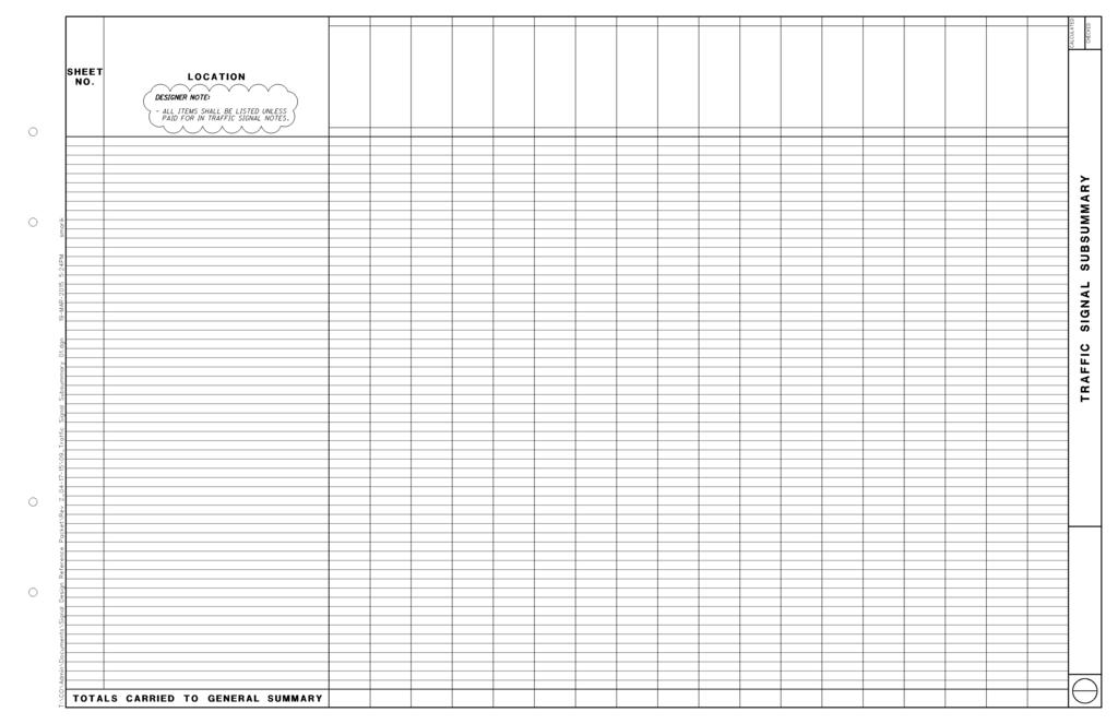
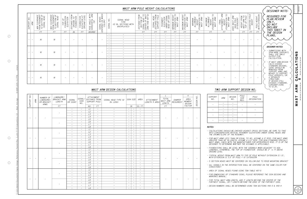
1 Office of Traffic Operations Signal Design Reference Packet Rev-2 04/17/2015 Contents The purpose of this packet is to provide guidance on designing and reviewing traffic signal plans. The format, legends, TEM tables/charts, page layouts, and sample details presented shall be used and followed as shown. Additionally, auto table/cadig shall be used to fill in all tables (including calculation spreadsheets). Failure to provide in such format may result in submittals not being approved. References for Traffic Signal Design Projects Detailed Design Review Submission Stages Signal Design/Review Checklist Traffic Signal Plan o Traffic Signal General Notes o Plan View o Plan Details o Coordination Plan o Subsummary Calculation Tables o Clearance Intervals o Conduit Sizing o Mast Arm Pole Height o Mast Arm Design No Typical Signal Head Placements Design files and spreadsheets are available for download and use on the Office of Traffic Operations website: Signal-Design-Reference-Packet.aspx
2 REFERENCES FOR TRAFFIC SIGNAL DESIGN PROJECTS ODOT Signals Documents and Publications Office of Traffic Operations Handbook* Traffic Authorized Products List (TAP)* ODOT Qualified Products List (QPL) Traffic Academy Ohio Manual of Uniform Traffic Control Devices (OMUTCD) Ed. Part 4, Highway Traffic Signals Part 5, Traffic Control Devices for Low-Volume Roads Part 6, Temporary Traffic Control (corrected page numbers for Chapters 6H and 6I 1/31/12) Part 7, Traffic Control for School Areas Part 8, Traffic Control for Railroad and Light Rail Transit Grade Crossings Part 9, Traffic Control for Bicycle Facilities Traffic Engineering Manual (TEM) Part 4 Signals Part 12 Zones and Traffic Engineering Studies Part 13 Intelligent Transportation Systems (Fiber Optics) Sign Designs and Markings Manual (SDMM) Construction & Material Specifications* 632 Traffic Signal Equipment 633 Traffic Signal Controllers 732 Traffic Signal Material 733 Traffic Signal Controller Material Supplements 1063 Signal Construction Personnel Requirements (631, 632, 633) 1076 Conflict Monitors for Use with Model 2070 Controllers/Cabinets Supplemental Specifications 800 Revisions to CMS 819 Railroad Preemption Interface 804 Fiber Optic Cable and Components 903 GPS Clock Assembly 805 GPS Clock Assembly 904 Fiber Optic Cable and Components 809 ITS Devices and Components 906 Spread Spectrum Radio 815 Spread Spectrum Radio 907 Video Detection System 816 Video Detection System 919 Railroad Preemption Interface Standard Construction Drawings - Highway Lighting (HL) HL HL HL HL HL HL Standard Construction Drawings - Maintaining Traffic (MT) MT MT Standard Construction Drawings - Traffic Control (TC) TC TC TC TC TC TC TC TC TC TC TC TC TC TC TC TC TC Traffic Signal Plan Insert Sheets (PIS) Foundations Protective Coating of Overhead Sign Support Sections Controller Cabinet Generator Power Panel Battery Backup System (BBS) Generator Power Panel Prepare to Stop When Flashing (PTSWF) Sign Installation Sepac Input File Information for 332 and 336 Cabinets Typical Pole Entrance Fitting Aerial Cable Placement Methods Cable Storage Details I Cable Storage Details II Miscellaneous Fiber Optic Details Typical Loose Tube Cable Installation Cable Construction Radio Interconnect Details Uninterruptible Power Supply (UPS) and Controller Cabinet Foundation Uninterruptible Power Supply (UPS) Foundation Retrofit Breakaway Transformer Base Connector Design Diamond Interchange 3-Phase Operation Diamond Interchange 4-Phase Operation Traffic Standard Drawings (Available upon request to the Office of Traffic Operations) Strain Pole and Mast Arm Camera Mount Location & Design Manual Volume 1 - Roadway Design Location & Design Manual Volume 2 - Drainage Design Location & Design Manual Volume 3 - Highway Plans *Note: Refer to the most current version.
3 DETAILED DESIGN/REVIEW SUBMISSION STAGES SCOPE Is consultant pre-qualified for basic and/or signal system design? Were the plans reviewed, submitted and stamped by the prequalified individual? Developer Signal Agreement (Completed and Accepted) Village Signal Permit (Documentation and Approvals) Does the project involve any if the following: Emergency Vehicle Preemption Rail Road Coordination/Preemption Coordinated with Rail Commission PTZ Cameras HAWK Signals STAGE 1 Title Sheet Plan and Profile Sheets Signal Warrants Signal Pole Locations Conceptual Maintenance of Traffic Revised Systems Engineering Analysis for Intelligent Transportation Systems (ITS) Projects (TEM ) Proprietary Item Approval(s) Coordination with Utilities (If poles are to be used for interconnect) Determine type of detection (radar, video, loops) STAGE 2 Title Sheet Maintenance of Traffic Sequence of Operations Revised Systems Engineering Analysis for Intelligent Transportation Systems (ITS) Projects (TEM ) Signal Plan Sheets Base plan drawn to scale of 1:20 including: Roadway base lines Underground and overhead utilities Overhead power lines should include their voltage Check stop bar locations with WB-62 turning template Traffic signal pole locations and skew angles, if required Identify reference numbers for all poles Signal head locations and direction; Identify the following: Signal heads having turn arrow lenses Louvers or special optically programmed features Signal head sizes Reference numbers for all signal heads Signal controller location and orientation Detector Locations Radar detection chart Traffic signal detector chart (Form 496-4) Underground conduit and pull boxes Overhead sign locations, whether on signal spans, mast arms, or located on separate supports Check cross sections for placement of poles/cabinets (in a ditch, with a steep slope, etc.) Legend for symbols used Pavement marking pertinent to the signal operation Signal phasing diagram, method of addressing yellow trap (where applicable) or field hookup chart (see Forms and ) and signal timing (see Forms and for typical signal timing charts) Handicap ramp locations Right-of-Way lines Corporation lines Any existing features to be incorporated into the new signal. Location of Power Service Any decision to reuse equipment must be based on a field check of the structural integrity and condition of the devices and agreement with the maintaining agency. Other physical features within the intersection and sidewalk area which may conflict with traffic flow, pedestrian flow, or sight distance Synchro files Design Calculations (use ODOT spreadsheets) Clearance Intervals Pedestrian Yellow All Red Conduit Sizing Pole loading calculations/swiss/mast Arm (TEM) Mast arm attachment height calculations ITS Plan Sheets Fiber Optic Cable Cost Estimate STAGE 3 Systems Engineering Analysis for Intelligent Transportation Systems (ITS) Projects (TEM ) Signal Plan Sheets General Notes Estimated quantities Special details Pole orientation chart Wiring diagram; Shall indicate the following: Type of cable Number of conductors connecting each signal head, pedestrian head, detector, push button, etc. Coordination timing (Shall be in seconds) Timing summary (coordination) Railroad preemption Interconnection Cost Estimate
4 SIGNAL DESIGN/REVIEW CHECKLIST SUPPLEMENTAL SPECS Number Title 800 Revisions to the 2013 Construction and Material Specifications [Date 8 weeks before letting] 804 Fiber Optic Cable and Components 805 GPS (Global Positioning System) Clock Assembly [Project w/ alternative to time base coord] 809 Intelligent Transportation System (ITS) Devices and Components 815 Spread Spectrum Radio (Serial Radios) 816 Video Detection System 819 Railroad Preemption Interface 903 GPS (Global Positioning System) Clock Assembly [For use on all projects using SS 805] 904 Fiber Optic Cable and Components 906 Spread Spectrum Radio 907 Video Detection System 919 Railroad Preemption Interface STANDARD CONSTRUCTION DRAWINGS (TYPICAL) Number Title HL Light Pole Styles HL Light Pole Details HL Pull Box Details I HL Roadway Conduit Details I HL Roadway Conduit Details II HL Pole Wiring I MT Typical Wiring Diagram for One Signal Head and One Detector MT New Signal Activation TC Foundations TC Miscellaneous Overhead Sign Support Details TC Sign Attachment Assemblies TC Yielding Post TC Typical Flat Sheet Sign Placement TC Strain Pole Details TC Single Arm Overhead Signal Support TC Vehicle Detector Installation Details TC Pole Mountings for Controllers and Power Service TC Cabinet Foundations and Pedestals TC Messenger Wire Details I TC Messenger Wire Details II TC Pole Mountings for Signal Heads TC Overhead Signal Attachment - Mast Arm TC Signal Tether Attachment TC Overhead Signal Attachments, Span Wire TC Railroad Preemption Interface Panel PLAN INSERT SHEETS Number Title Foundations Protective Coating of Overhead Sign Support Sections Controller Cabinet Generator Power Panel Battery Backup System (BBS) Generator Power Panel Prepare to Stop When Flashing (PTSWF) Sign Installation Sepac Input File Information for 332 and 336 Cabinets Typical Pole Entrance Fitting Aerial Cable Placement Methods Cable Storage Details I Cable Storage Details II Miscellaneous Fiber Optic Details Typical Loose Tube Cable Installation Cable Construction Radio Interconnect Details Uninterruptible Power Supply (UPS) and Controller Cabinet Foundation Uninterruptible Power Supply (UPS) Foundation Retrofit Breakaway Transformer Base Connector Design Diamond Interchange 3-Phase Operation Diamond Interchange 4-Phase Operation TRAFFIC STANDARD DRAWINGS Number Title TBD Strain Pole and Mast Arm Camera Mount FHWA PROPRIETARY EQUIPMENT APPROVALS (FOR ODOT USE ONLY) Type Title Cellular Modem Sierra Wireless 3G Airlink Raven X Cellular Modem Sierra Wireless 4G Airlink GX440 Detector Wavetronix Matrix (Model SS-225) Detector Wavetronix Smartsensor Advance (Model SS-200E)
5 SIGNAL DESIGN/REVIEW CHECKLIST TEM GENERAL NOTES (TYPICAL) Number Name Power Supply for Traffic Signals 442-3* Signal Activation Removal of Traffic Signal Installation Interconnect Cable, Misc.: (by Size), with Support Messenger, As Per Plan Loop Detector Units, by Type, As Per Plan Detection Maintenance 442-8* Work Inspection Loop Detector Lead-In Cable, Direct Burial Combination Signal Support, Type TC and Sign Support, TC- (with Light Pole Extension) , Combination Strain Pole, Type TC and Sign Support. TC- (with Light Pole Extension) Strain Pole and Pedestal Foundation Elevations Vehicular Signal Head, LED, Black, (By Type), With Backplate, As Per Plan * Guarantee Alternate Bid Item Pedestrian Signal Head (LED), (Countdown), Type D2, As Per Plan Relamp Existing Signal Section with LED Lamp Unit, By Lens Type, As Per Plan Controller Unit, Type 2070E, with Cabinet, By Type, As Per Plan Controller, Master, Traffic Responsive, As Per Plan Controller Unit, Type TS2/A2, with Cabinet, Type TS2, As Per Plan Preemption Preemption Receiving Unit Preemption Detector Cable Preempt Phase Selector Preempt Confirmation Light, LED Pull Box, 24 X 35 X Pole Entrance Fitting * Grounding and Bonding Uninterruptible Power Supply (UPS), Battery Replacement Uninterruptible Power Supply (USP), 1000 Watt, As Per Plan Signal Support, Mechanical Damper for TC Mast Arm (Greater Than 59 in Length), As Per Plan Signal Support, (By Type), As Per Plan Signalization, Misc.: Unlash and Relash Messenger Wire General Electrical Requirements for Solar-Powered Devices * Maintenance of Traffic Signal/Flasher Installation * Designates REQUIRED Signal Notes SPECIALTY NOTES Number OTO OTO OTO OTO OTO TEM FORMS AND FIGURES Number Name Signal Operation Changed 632 Signal Support Foundation 632 Signalization, Misc.: Cellular Modem, Furnish Only 809 Advance Radar Detection 809 Stop-Bar Radar Detection Name Traffic Signal Controller Timing Chart for Actuated Signals Traffic Signal Detector Chart Radar Detection Chart Coordination Timing Chart Field Wiring Hook-Up Chart Vehicular/Ped Volume Chart Plan Details for Strain Poles Plan Details for Signal Supports - Arm Lengths Plan Details for Signal Supports - Mast Arm Orientation Wiring Diagram Phasing Diagram DESIGNER NOTES: - FOR OTO NOTES, PLEASE CONTACT THE OFFICE OF TRAFFIC OPERATIONS. - AS PER PLAN NOTES AND ITEMS ARE USED WHEN MODIFICATIONS ARE MADE TO THE BASE ITEM/STANDARD NOTE. TYPICAL EXTENSION NUMBERS ARE 1 HIGHER THAN THE ORIGINAL ITEM. CHECK CONSTRUCTION ITEM MASTER FOR EXACT NUMBERS. Construction/Forms/ItemMaster.aspx
6 SIGNAL DESIGN/REVIEW CHECKLIST PAY ITEMS (TYPICAL) Item Ext. Unit Description SQ FT Curb Ramp SQ FT Truncated Domes EACH Connection, Fused Pull Apart EACH Connection, Unfused Permanent 625 VARIES EACH Bracket Arm, XX', As Per Plan 625 VARIES FT No. XX AWG 600 Volt Distribution Cable 625 VARIES FT No. XX AWG Pole And Bracket Cable FT Conduit, 2", FT Conduit, 3", FT Conduit, 4", FT Conduit, Jacked Or Drilled, (Specify Size) EACH Luminaire, Conventional, 250w HPS, 120 Volt, As Per Plan FT Trench EACH Pull Box, , 18" EACH Pull Box, , 24" EACH Ground Rod 632 VARIES EACH Vehicular Signal Head, (LED), Black, X-Section, 12" Lens, 1-Way, Polycarbonate With Backplate, As Per Plan EACH Pedestrian Signal Head (LED), (Countdown), Type D2, As Per Plan EACH Covering Of Vehicular Signal Head EACH Covering Of Pedestrian Signal Head EACH Pedestrian Pushbutton, As Per Plan EACH Detector Loop 632 VARIES FT Signal Cable, X Conductor, No. X AWG EACH Signal Support Foundation EACH Pedestal Foundation FT Loop Detector Lead-In Cable 632 VARIES FT Power Cable, X Conductor, No. X AWG 632 VARIES FT Service Cable, X Conductor, No. X AWG EACH Power Service, As Per Plan 632 VARIES EACH Signal Support, Type TC-81.21, Design XX, As Per Plan 632 VARIES EACH Combination Signal Support, Type TC-81.21, Design XX, As Per Plan EACH Signal Support, Mechanical Damper For Tc Mast Arm (Greater Than 59 In Length) 632 VARIES EACH Strain Pole, Type TC-81.10, Design XX 632 VARIES EACH Combination Strain Pole, Type TC-81.10, Design XX, As Per Plan 632 VARIES EACH Pedestal, X', Transformer Base EACH Removal Of Traffic Signal Installation, As Per Plan EACH Signalization, Misc.: CDMA Modem, Furnish Only EACH Controller Unit, Type TS2/A2, With Cabinet, Type TS2, As Per Plan PAY ITEMS (TYPICAL) EACH Controller Unit, Type TS2/A2, With Cabinet, Type TS EACH Controller Unit, Type 2070E, With Cabinet, Type 332, As Per Plan EACH Controller Unit, Type 2070E, With Cabinet, Type 336, As Per Plan EACH Cabinet Riser EACH Cabinet Foundation EACH Controller Work Pad EACH Flasher Controller EACH Uninterruptible Power Supply (UPS), 1000 Watt, As Per Plan FT Fiber Optic Cable, 18 Fiber FT Fiber Optic Cable, 24 Cable FT Fiber Optic Cable, 48 Cable FT Fiber Optic Cable, Armored, 18 Fiber FT Fiber Optic Cable, Armored, 24 Fiber FT Fiber Optic Cable, Armored, 36 Fiber FT Fiber Optic Cable, Armored, 48 Fiber EACH Fiber Optic Patch Cord, 2 Fiber EACH Termination Panel, 12 Fiber EACH Termination Panel, 24 Fiber EACH Termination Panel, 36 Fiber EACH Termination Panel, 48 Fiber EACH Splice Enclosure EACH Global Positioning System Clock Assembly EACH Closed Loop Arterial Traffic Signal System EACH Centrally Controlled Arterial Traffic Signal System EACH Highway Rail/Traffic Signal Pre-Emption EACH Traffic Signal System With Emergency Vehicle Pre-Emption EACH Traffic Signal System With Transit Priority EACH Adaptive Traffic Signal Control System EACH Side-Fired Radar Detector EACH Advance Radar Detection EACH Stop-Bar Radar Detection EACH Stop-Bar And Advance Radar Detection EACH Spread Spectrum Radio Note: Pay Items listed are TYPICAL. Go to the ODOT Item Master for complete list. DESIGNER NOTE: - PLANS THAT INCLUDE FIBER OPTIC CABLE SHALL BE SUBMITTED TO OTO ITS SECTION FOR REVIEW
7
8
9
10
11
12
13
14
15
16
17
18
19
20 ODOT Typical Signal Head Placements 3 UNIT SIGNAL HEAD 3 UNIT PROTECTED LEFT TURN SIGNAL HEAD 5 UNIT PROTECTED/PERMISSIVE LEFT TURN SIGNAL HEAD 5 UNIT SIGNAL HEAD FOR RIGHT TURN OVERLAPS NOTES A MINIMUM OF TWO THROUGH SIGNAL FACES IS ALWAYS REQUIRED FOR THE PRIMARY MOVEMENT. THE REQUIRED SIGNAL FACES FOR THROUGH TRAFFIC ON AN APPROACH SHALL BE LOCATED NOT LESS THAN 8 FEET APART MEASURED HORIZONTALLY PERPENDICULAR TO THE APPROACH BETWEEN CENTERS OF THE SIGNAL FACES. IF A PROTECTED-PERMITTED LEFT-TURN MODE IS USED WITH SHARED SIGNAL FACE [IT] SHALL BE LOCATED OVER THE PROJECTION OF THE LANE LINE BETWEEN THE LEFT-TURN AND THROUGH LANES. ANY PRIMARY SIGNAL FACE FOR AN EXCLUSIVE TURN LANE SHOULD BE LOCATED OVER THE CENTER OF EACH EXCLUSIVE TURN LANE. IT SHALL NOT BE POSITIONED ANY FURTHER TO THE RIGHT OF THE EXTENSION OF THE RIGHT-HAND EDGE OF THE EXCLUSIVE TURN LANE OR ANY FURTHER TO THE LEFT THAN THE EXTENSION OF THE LEFT-HAND EDGE OF THE EXCLUSIVE TURN LANE. FOR APPROACHES OF 45 MPH OR GREATER, WITH TWO OR MORE THROUGH LANES, PROVIDE ONE SIGNAL FACE PER THROUGH LANE. (SEE TABLE 4D-1 OF OMUTCD) FOR APPROACHES OF 45 MPH OR GREATER, WITH TWO OR MORE TOTAL APPROACH LANES, ADD A SUPPLEMENTAL SIGNAL HEAD. SIGNAL FACES MOUNTED AT THE SIDE OF THE ROADWAY WITH CURBS AT LESS THAN 15 FEET FROM THE BOTTOM OF THE HOUSING OR ATTACHMENTS SHALL HAVE A HORIZONTAL OFFSET OF NOT LESS THAN 2 FEET FROM THE FACE OF VERTICAL CURB OR EDGE OF SHOULDER IF NO CURB. NEAR SIDED, SUPPORT POLE MOUNTED, SUPPLEMENTAL HEADS SHOULD BE CONSIDERED WHEN TRUCK VOLUMES ARE GREATER THAN 20%, OR IF SIGHT DISTANCE IS LIMITED. * See 2012 OMUTCD Section 4D.10 for additional layouts
21 ODOT Typical Signal Head Placements 3 UNIT SIGNAL HEAD 3 UNIT PROTECTED LEFT TURN SIGNAL HEAD 5 UNIT PROTECTED/PERMISSIVE LEFT TURN SIGNAL HEAD 5 UNIT SIGNAL HEAD FOR RIGHT TURN OVERLAPS 2' inside center line Over edge line Center over lane line Over edgeline 2' inside center line Center over lane line * Spacing could vary depending on lane width, 8' minimum. * * Spacing could vary depending on lane width, 8' minimum. 3 or 5 unit head * Spacing could vary depending on lane width, 8' minimum. * 3 or 5 unit head 2' 2' Single Lane Approach Protected/permissive left, thru/right or Unprotected left, thru/right Thru/left, protected/permissive right (overlap) or Thru/left, permissive right Center head over approach lane 2' right of lane line Over edgeline Center heads over approach lanes 2' left of lane line Over center line Center head over approach lane * Spacing could vary depending on lane width, 8' minimum. * 2' Protected only left, thru/right Two Lane Approach Notes: Signal head configuration may vary depending on preference. Per OMUTCD 4D.11, a minimum of two primary signal faces shall be provided for the signalized turning movement that is considered to be the major movement from the approach. 2' 2 Lane T Intersection/Ramp * * Spacing could vary depending on lane width, 8' minimum. * See 2012 OMUTCD Section 4D.10 for additional layouts
22 ODOT Typical Signal Head Placements 3 UNIT SIGNAL HEAD 3 UNIT PROTECTED LEFT TURN SIGNAL HEAD 5 UNIT PROTECTED/PERMISSIVE LEFT TURN SIGNAL HEAD 5 UNIT SIGNAL HEAD FOR RIGHT TURN OVERLAPS Center heads over approach lanes Center over lane lines Center heads over approach lanes 5 unit w/lt & RT Arrows 3 or 5 unit head 3 Lane T Intersection Protected/permissive left, thru, right turn lane Protected only left, thru, right turn lane Center head over approach lane 2' right of lane line Center over lane line Center over lane lines Center heads over approach lanes 2' Protected only left, thru, right turn lane (w/ overlap) Protected/permissive left, thru, thru/right Protected only left, thru, thru/right * See 2012 OMUTCD Section 4D.10 for additional layouts
23 ODOT Typical Signal Head Placements 3 UNIT SIGNAL HEAD 3 UNIT PROTECTED LEFT TURN SIGNAL HEAD 5 UNIT PROTECTED/PERMISSIVE LEFT TURN SIGNAL HEAD 5 UNIT SIGNAL HEAD FOR RIGHT TURN OVERLAPS Center heads over approach lanes 2' right of lane line Over edgeline 2'* left of lane line Over center line Center heads over approach lanes Center over lane lines * Spacing could vary depending on lane width, 8' minimum. * * * Spacing could vary depending on lane width, 8' minimum. 3 or 5 unit head 2' 2' Dual left, thru/right Thru/Left, Double Right Protected/permissive left, 2 thru, right turn lane Center heads over approach lanes Center head over approach lane 3'* left of lane line * * Center over lane line * Distance between heads shall be consistent; 8' minimum. Center heads over approach lanes 3'* Protected only left, 2 thru, right turn lane Protected only left, 2 thru, right turn lane (w/ overlap) Dual left, thru, thru/right * See 2012 OMUTCD Section 4D.10 for additional layouts

 * See 2012 OMUTCD Section 4D.")
24 ODOT Typical Signal Head Placements 3 UNIT SIGNAL HEAD 3 UNIT PROTECTED LEFT TURN SIGNAL HEAD 5 UNIT PROTECTED/PERMISSIVE LEFT TURN SIGNAL HEAD 5 UNIT SIGNAL HEAD FOR RIGHT TURN OVERLAPS Center heads over approach lanes Dual left, 2 thru, right turn lane Center heads over approach lanes 3' left of lane line Center over lane line * * * Distance between heads shall be consistent. 3' Dual left, 2 thru, right turn lane (w/ overlap) * See 2012 OMUTCD Section 4D.10 for additional layouts
SECTION 5900 TRAFFIC SIGNALS CITY OF LEE S SUMMIT, MISSOURI DESIGN CRITERIA
 SECTION 5900 TRAFFIC SIGNALS CITY OF LEE S SUMMIT, MISSOURI DESIGN CRITERIA TABLE OF CONTENTS Section Title Page 5901 GENERAL... 2 5902 DESIGN CRITERIA... 2 5902.1 Codes and Standards... 2 5902.2 Signal
400 TRAFFIC SIGNALS Traffic Engineering Manual
 TABLE OF CONTENTS Part 4 - SIGNALS 400 GENERAL... 4-9 400-1 Introduction... 4-9 400-2 Construction Projects... 4-9 400-3 Force Account (ODOT Operations) Work... 4-9 401 TRAFFIC CONTROL SIGNALS - GENERAL...
TRAFFIC SIGNAL DESIGN GUIDELINES
 TRAFFIC SIGNAL DESIGN GUIDELINES January, 2006 INDEX PLAN APPROVAL PROCESS 1 1. Designer Prequalification 1 2. Items Available from the County 1 3. Plan Submittals 1 4. Final Submittal 1 5. Checklist for
CHAPTER 14 WIRING SIGNALS AND LIGHTING FIELD GUIDE Wiring Requirements WIRING
 WIRING CHAPTER 14 WIRING The installation of all wiring, including electrical cables and conductors, must conform to the National Electrical Code (NEC). The Code represents the minimum required standard.
Work Type Definition and Submittal Requirements. Work Type Definition: Traffic Signal Design
 The first section, Work Type Definition, provides a detailed explanation of the work type. The second section, Work Type Submittal Requirements, identifies the requirements a firm must meet to become pre-qualified
STATE OF OHIO DEPARTMENT OF TRANSPORTATION SUPPLEMENTAL SPECIFICATION 872 LIGHT EMITTING DIODE TRAFFIC SIGNAL LAMP UNITS JULY 19, 2002
 STATE OF OHIO DEPARTMENT OF TRANSPORTATION SUPPLEMENTAL SPECIFICATION 872 LIGHT EMITTING DIODE TRAFFIC SIGNAL LAMP UNITS JULY 19, 02 872.01 Description 872.02 Prequalification 872.03 Material Requirements
CONSTRUCTION SPECIFICATION FOR TRAFFIC SIGNAL EQUIPMENT
 ONTARIO PROVINCIAL STANDARD SPECIFICATION METRIC OPSS.PROV 620 APRIL 2017 CONSTRUCTION SPECIFICATION FOR TRAFFIC SIGNAL EQUIPMENT TABLE OF CONTENTS 620.01 SCOPE 620.02 REFERENCES 620.03 DEFINITIONS 620.04
March 4 th, Addendum No. 1. Brooklyn College Systems Integrator Broadcast Television Equipment Project No: BY019/
 Facilities Planning, Construction, and Management Office of Financial Management Procurement Services 555 West 57 th Street 11 th Floor New York, New York 10019 CUNY.Builds@mail.cuny.edu March 4 th, 2013
Special Provision Fiber Optic Cable Section 643. The Contractor shall install fiber optic cable in conduit where shown on the plan sheets.
 Special Provision Fiber Optic Cable Section 643 The Contractor shall install fiber optic cable in conduit where shown on the plan sheets. ATRC Fiber Optic Specifications: To ensure compatibility and proper
September 28, 2018 CITY OF BERKELEY JOHN MUIR SCHOOL CROSSING IMPROVEMENTS SPECIFICATION NO C ADDENDUM NO. 2
 Department of Public Works Transportation Division September 28, 2018 CITY OF BERKELEY JOHN MUIR SCHOOL CROSSING IMPROVEMENTS ADDENDUM NO. 2 Dear Bidder: The following amendments are hereby made to the
SECTION FIVE COBB COUNTY TRAFFIC SIGNAL SPECIFICATIONS
 SECTION FIVE COBB COUNTY TRAFFIC SIGNAL SPECIFICATIONS COBB COUNTY DOT TRAFFIC SIGNAL SPECIFICATIONS OCTOBER 2017 Table of Contents Section 647 Traffic Signal Installation 4 Section 687 Signal Timing 35
SPECIAL SPECIFICATION 8311 LED Countdown Pedestrian Signal Module
 2004 Specifications CSJ 0542-06-041, Etc. SPECIAL SPECIFICATION 8311 LED Countdown Pedestrian Signal Module 1. Description. Furnish and install LED Walking Person and Hand icon pedestrian signal modules
Coastal Carolina University RE-BID WILLIAMS BRICE RENOVATION AND REPAIR October 19, 2018 Construction Documents
 PART 1 - GENERAL 1.1 SUMMARY SECTION 271500 COMMUNICATIONS HORIZONTAL CABLING A. Section Includes: 1. UTP cabling. 2. Telecommunications outlet/connectors. 3. Cabling system identification products. 1.2
SECTION COMMUNICATIONS HORIZONTAL CABLING
 SECTION 271500 COMMUNICATIONS HORIZONTAL CABLING PART 1 - GENERAL 1.1 SUMMARY A. Section Includes: 1. UTP cabling. 2. Telecommunications outlet/connectors including patch panels. 3. Cabling identification
BILOXI PUBLIC SCHOOL DISTRICT. Biloxi Junior High School
 BILOXI PUBLIC SCHOOL DISTRICT Biloxi Junior High School Request for Proposals E-Rate 2014-2015 - Internal Connections Submit Proposals To: Purchasing Department Attn: Traci Barnett 160 St. Peter Street
TEO Signal Committee Meeting Minutes Meeting Date: 05/19/2009 Waters Edge Conference Rm 176 Meeting Time: 9:00am - Noon
 TEO Signal Committee Meeting Minutes Meeting Date: 05/19/2009 Waters Edge Conference Rm 176 Meeting Time: 9:00am - Noon Meeting Attendees: Kile Holm Sue Zarling Curt Krohn Mike Schroeder Tim Bangsund Jeff
Old Business. TEO Signal Committee Meeting Minutes Waters Edge Conf. Room C September 16, 2004
 Attendees: Jerry Kotzenmacher Ray Star Mike Wolf Marlin Reinardy Kevin Schwartz Greg Gruber Roger Sowder Mike Gerbenski Jim Deans Tom Dumont Kile Holm Ben Osemenam Old Business TEO Signal Committee Meeting
IndyGo Facility Upgrades Project 35671EE
 SECTION 260553 IDENTIFICATION FOR ELECTRICAL SYSTEMS PART 1 - GENERAL 1.1 SUMMARY A. Section Includes: 1. Identification for raceways. 2. Identification of power and control cables. 3. Identification for
U-verse Outside Plant Cabinets AT&T Knowledge Ventures. All rights reserved. AT&T and the AT&T logo are trademarks of AT&T Knowledge Ventures.
 U-verse Outside Plant s U-verse Outside Plant (OSP) Certifications AT&T certifies that Lightspeed cabinets, wiring and equipment have been inspected for and are compliant to the following industry standards:
Mediacom Upgrade/Splicing Procedures (based on original document from Corporate dated 4/16/98)
") Mediacom Upgrade/Splicing Procedures (based on original document from Corporate dated 4/16/98) 1. Splicing specifications are provided by Mediacom, but due to resplice conditions, many locations become
Mediacom Upgrade/Splicing Procedures (based on original document from Corporate dated 4/16/98) 1. Splicing specifications are provided by Mediacom, but due to resplice conditions, many locations become
2.1 SIGNAL DESIGN ELEMENTS
 SECTION 2 2.0 TRAFFIC SIGNAL DESIGN GUIDELINES 2.1 SIGNAL DESIGN ELEMENTS Any traffic signal proposed for installation on City streets shall meet the minimum criteria as outlined in the Manual on Uniform
JAMAR TRAX RD Detector Package Power Requirements Installation Setting Up The Unit
 JAMAR TRAX RD The TRAX RD is an automatic traffic recorder designed and built by JAMAR Technologies, Inc. Since the unit is a Raw Data unit, it records a time stamp of every sensor hit that occurs during
SPECIAL SPECIFICATION 8540 Telecommunication Cable
 2004 Specifications CSJ 0914-00-307 & CSJ 0914-25-003 SPECIAL SPECIFICATION 8540 Telecommunication Cable 1. Description. This specification governs the materials, installation, termination, splicing, testing,
Special Specification 6002 Video Imaging Vehicle Detection System
 6002 Special Specification 6002 Video Imaging Vehicle Detection System 1. DESCRIPTION 2. DEFINITIONS Install a Video Imaging Vehicle Detection System (VIVDS) that monitors vehicles on a roadway via processing
ACADEMIC SUCCESS CENTER THE COLLEGE AT BROCKPORT STATE UNIVERSITY OF NEW YORK PROJECT NO
 SECTION 270536 - CABLE TRAYS FOR COMMUNICATIONS SYSTEMS PART 1 - GENERAL 1.1 RELATED DOCUMENTS A. Drawings and general provisions of the Contract, including General and Supplementary Conditions and Division
All Dielectric Self Supporting (ADSS) Fiber Optic Cable Installation
 Fiber Optic Cable Installation") All Dielectric Self Supporting (ADSS) Fiber Optic Cable Installation Underground Installation M P - 1012 Issue #3 March 2011 DISCLAIMER OF WARRANTIES AND LIMITATION OF LIABILITIES The practices contained
All Dielectric Self Supporting (ADSS) Fiber Optic Cable Installation Underground Installation M P - 1012 Issue #3 March 2011 DISCLAIMER OF WARRANTIES AND LIMITATION OF LIABILITIES The practices contained
SPECIAL SPECIFICATION 6559 Telecommunication Cable
 2004 Specifications CSJ 0015-09-147, etc. SPECIAL SPECIFICATION 6559 Telecommunication Cable 1. Description. This specification governs the materials, installation, termination, splicing, testing, training,
Aerial Cable Installation Best Practices
 Aerial Cable Installation Best Practices Panduit Corp. 2007 BEST PRACTICES Table of Contents 1.0 General... 3 2.0 Introduction... 3 3.0 Precautions... 4 4.0 Pre-survey... 5 5.0 Materials and Equipment...
The University of Texas at Austin September 30, 2011
 SECTION 27 08 20 COPPER TESTING PART 1 - GENERAL 1.1 SUMMARY A. Test measurements shall be taken for all balanced-twisted pair cabling, including horizontal and backbone copper cables and wall-to-rack
NEXT/RADIUS Shelf Mount CCU
 2018 NEXT/RADIUS Shelf Mount CCU The Next / Radius shelf mount CCU is open for orders and is available to ship mid September. CCU information on pages 3 and 7. September 11, 2018 VantageRadius Radar technology
Reno A & E, 4655 Aircenter Circle, Reno, NV (775)
") Product: MMU-1600 Title: Monitoring Flashing Yellow Arrow Left Turns Release Date: February 06, 2009 Scope: All Reno A&E Monitors. The following Reno A&E monitors now support Flashing Yellow Arrow (FYA)
Product: MMU-1600 Title: Monitoring Flashing Yellow Arrow Left Turns Release Date: February 06, 2009 Scope: All Reno A&E Monitors. The following Reno A&E monitors now support Flashing Yellow Arrow (FYA)
HONEYWELL VIDEO SYSTEMS HIGH-RESOLUTION COLOR DOME CAMERA
 Section 00000 SECURITY ACCESS AND SURVEILLANCE HONEYWELL VIDEO SYSTEMS HIGH-RESOLUTION COLOR DOME CAMERA PART 1 GENERAL 1.01 SUMMARY The intent of this document is to specify the minimum criteria for the
Primex Wireless, Inc. July, Wells Street Lake Geneva, WI
 Division 0 0 0 0 Primex Wireless, Inc. July, 00 Wells Street Lake Geneva, WI 00--0 www.primexwireless.com Product Guide Specification Specifier Note: This product specification is written according to
Identification - electrical services
 Identification - electrical services Aesthetic All live phase cable sheathing to be brown coloured and neutral phase cable sheathing to be blue coloured, all labelled L1, L2, L3 & N respectively in accordance
SPECIAL SPECIFICATION 6911 Fiber Optic Video Data Transmission Equipment
 2004 Specifications CSJ 3256-02-079 & 3256-03-082 SPECIAL SPECIFICATION 6911 Fiber Optic Video Data Transmission Equipment 1. Description. Furnish and install Fiber Optic Video Data Transmission Equipment
GS122-2L. About the speakers:
 Dan Leighton DL Consulting Andrea Bell GS122-2L A growing number of utilities are adapting Autodesk Utility Design (AUD) as their primary design tool for electrical utilities. You will learn the basics
Special Specification 6293 Adaptive Traffic Signal Control System
 Special Specification Adaptive Traffic Signal Control System 1. DESCRIPTION 2. MATERIALS Furnish, install, relocate, or remove adaptive traffic signal control (ATSC) system software and equipment at locations
SPECIAL SPECIFICATION 1291 Fiber Optic Video Data Transmission Equipment
 1993 Specifications CSJ 0500-01-117 SPECIAL SPECIFICATION 1291 Fiber Optic Video Data Transmission Equipment 1. Description. This Item shall govern for the furnishing and installation of Fiber Optic Video
Minimum qualifications for the Telecommunications Engineer are: A. Texas Licensed Profession Engineer (PE)
") PART 1: GENERAL 1.01 Telecommunications Engineer Minimum qualifications for the Telecommunications Engineer are: A. Texas Licensed Profession Engineer (PE) B. Registered Communications Distribution Designer
PART 1: GENERAL 1.01 Telecommunications Engineer Minimum qualifications for the Telecommunications Engineer are: A. Texas Licensed Profession Engineer (PE) B. Registered Communications Distribution Designer
Guidelines for Wiring, Electronic Timing and Scoring Systems Table of Contents
 Guidelines for Wiring, Electronic Timing and Scoring Systems Table of Contents 1. INTRODUCTION PAGE 2 2. VELORESULTS PAGE 2 3. 250 METER TRACK PAGE 2 4. STARTERS STAND PAGE 2-3 5. JUDGES STAND PAGE 3 6.
TruePlate Structural Plate
 TruePlate Structural Plate Galvanized Steel and Aluminum Alloy Sizes, Shapes and Height of Cover Tables TrueNorthSteel.com info@truenorthsteel.com 866-82-511 TruePlate Structural Plate Many drainage and
>> By Jason R. Kack, LS
 hen the Utah Department of Transportation (UDOT) set out to rebuild Interstate 15 south of Salt Lake City, the department needed accurate one-foot contour interval mapping and a digital terrain model (DTM).
OptiTect Premier Local Convergence Cabinet An Evolant Solutions Product
 Description The OptiTect Premier Local Convergence Cabinet family provides everything necessary to manage 44, 288 and 432 distribution fibers for an outside plant FTTx application. The OptiTect Premier
SPECIAL SPECIFICATION 6740 Video Imaging Vehicle Detection System
 1995 Metric CSJ s 0918-45-344 & 0008-08-059 SPECIAL SPECIFICATION 6740 Video Imaging Vehicle Detection System 1. Description. Install a Video Imaging Vehicle Detection System (VIVDS) that monitors vehicles
ROAD COMMISSION FOR OAKLAND COUNTY SPECIAL PROVISION FOR LIGHT EMITTING DIODE (LED) VEHICLE TRAFFIC SIGNALS
 VEHICLE TRAFFIC SIGNALS") ROAD COMMISSION FOR OAKLAND COUNTY SPECIAL PROVISION FOR LIGHT EMITTING DIODE (LED) VEHICLE TRAFFIC SIGNALS RCOC/TOC: DD Page 1 of 9 RCOC12TOC820E a. General Requirements Furnish all labor, equipment,
ROAD COMMISSION FOR OAKLAND COUNTY SPECIAL PROVISION FOR LIGHT EMITTING DIODE (LED) VEHICLE TRAFFIC SIGNALS RCOC/TOC: DD Page 1 of 9 RCOC12TOC820E a. General Requirements Furnish all labor, equipment,
Target Interface / Construction Compliance Inspection Checklist
 A. Targets Quantities meet DD, applicable TC -, and CEHNC Design Guide 0-- (Standard is single UTOs and Double UTOs) B. Roads-Service, Lanes Adequate access is provided to the and AAR D. Testing Results-provided
SATELLITE TV OPERATION / TECHNICAL MANUAL. Eagle II Controller
 SATELLITE TV OPERATION / TECHNICAL MANUAL Eagle II Controller 10 May 2018 2 Index Warnings... 4 Mount Definitions... 5 Controller Views... 6 Configuration and Software Versions... 8 Menus and Operations...
ADDENDUM NO. 6 PORT OF NOME SECURITY CAMERA PROJECT RFP
 P.O. Box 281 o Nome, Alaska 99762 ADDENDUM NO. 6 DATE: May 22, 2017 TO: Proposers FROM: Joy Baker, Project Manager RE: PORT OF NOME SECURITY CAMERA PROJECT RFP NOTES TO PROPOSERS: The Proposal submittal
Structural Plate Design Guide. 5 th Edition MULTI-PLATE. Aluminum Structural Plate. Aluminum Box Culvert SUPER-SPAN SUPER-PLATE.
 ENGINEERED SOLUTIONS Structural Plate Design Guide 5 th Edition MULTI-PLATE Aluminum Structural Plate SUPER-SPAN SUPER-PLATE BridgeCor Table of Contents Steel and Aluminum Structural Plate design guide.
Film-Tech. The information contained in this Adobe Acrobat pdf file is provided at your own risk and good judgment.
 Film-Tech The information contained in this Adobe Acrobat pdf file is provided at your own risk and good judgment. These manuals are designed to facilitate the exchange of information related to cinema
Azatrax Model Railroad Track Signal Control - Single Track
 Installation Guide Azatrax Model Railroad Track Signal Control - Single Track TS2 What it is: The TS2 operates one or two trackside block signals (one in each direction) on one track to simulate the block
Cambria County Association for the Blind and Handicapped 175 Industrial Park Road Ebensburg, PA Prepared for: Prepared by:
 Cable Management in Solar PV Arrays: A Review of Requirements in the National Electrical Code and how CAB Cable Rings and Saddles Meet These Requirements Prepared for: Cambria County Association for the
Public Works Division Lighting District Fiber Optic Specifications April 2009
 Public Works Division Lighting District Fiber Optic Specifications April 2009 7000 Florida Street Punta Gorda, Florida 33950 Tele: 941.575.3600 Fax : 941.637.9265 www.charlottecountyfl.com/publicworks
MMU2-16LE FYA Overview
 2016 MMU2-16LE FYA Overview The history of the Flashing Yellow Arrow (FYA), how it came about and what you need to know to program an intersection for the feature. March 15, 2016 MMU2-16LE FYA Overview
Traffic Signal Timing Maintenance. Division of Traffic Control Services. Organization. Division of Traffic Control Systems
 Traffic Signal Timing Maintenance Division of Traffic Control Systems Division of Traffic Control Services Tasked with: Assisting the District Traffic Systems Engineers with retiming coordinated signals
Request for Proposals Fiber Optic Network Backbone Upgrades
 Introduction Request for Proposals Fiber Optic Network Backbone Upgrades RFP Released on February 18, 2015 The Dexter R-11 Public School District is seeking proposals from qualified service providers to
SATELLITE TV OPERATION / TECHNICAL MANUAL. Eagle II Controller
 SATELLITE TV OPERATION / TECHNICAL MANUAL Eagle II Controller 8 Nov 2017 2 Index Warnings... 4 Mount Definitions... 5 Controller Views... 6 Configuration and Software Versions... 8 Menus and Operations...
210E - 210ECL ECL ECL
 210E - 210ECL - 2010ECL - 2018ECL RMS Signal Monitor Operations Manual THIS MANUAL CONTAINS TECHNICAL INFORMATION FOR THE FOLLOWING SERIES OF MODEL 210/2010/2018 SIGNAL MONITORS, PCB Issue G: 210E, 210ECL,
1993 Specifications CSJ , etc. SPECIAL SPECIFICATION ITEM CCTV Central Equipment
 1993 Specifications CSJ 0922-33-042, etc. SPECIAL SPECIFICATION ITEM 8549 CCTV Central Equipment 1. Description. This Item shall govern for the furnishing and installation of closed circuit television
MILITARY SPECIFICATION SHEET
 INCH POUND MIL-S-22885/100A 16 May 2003 SUPERSEDING MIL-S-22885/100 (USAF) 27 August 1982 MILITARY SPECIFICATION SHEET SWITCH, PUSH BUTTON, ILLUMINATED, 4-LAMP, SPDT AND DPDT, 7.5 AMPERES, SILVER CONTACTS,
MATERIAL SPECIFICATION FOR SIGNAL HEADS
 ONTARIO PROVINCIAL STANDARD SPECIFICATION METRIC OPSS 2461 NOVEMBER 2007 MATERIAL SPECIFICATION FOR SIGNAL HEADS TABLE OF CONTENTS 2461.01 SCOPE 2461.02 REFERENCES 2461.03 DEFINITIONS 2461.04 DESIGN AND
OCC Installation Round Messenger Guidelines Excerpt from Optical Cable Corporation s INSTALLATION GUIDE
 Installation Round Messenger Guidelines Excerpt from Optical Cable Corporation s INSTALLATION GUIDE Round Messenger (ADSS) A round messenger fiber optic cable is designed for use in aerial installations
MonitorKey Operation Manual: content/uploads/ MonitorKey Operation Manual.pdf
 Additional Resources: MonitorKey Operation Manual: www.editraffic.com/wp content/uploads/888 1212 001 MonitorKey Operation Manual.pdf CMUip 2212 Operation Manual: www.editraffic.com/wp content/uploads/888
INSTALLATION INSTRUCTIONS FOR
 INSTALLATION INSTRUCTIONS FOR MODEL 2240LED www.sportablescoreboards.com 1 Table of Contents 8 X 7 INDOOR SCOREBOARD... 3 THE SCOREBOARD SYSTEM SHOULD INCLUDE THE FOLLOWING PARTS:... 3 INSTRUCTIONS FOR
SECTION 683 VIDEO OPTICAL TRANSCEIVER WITH BI-DIRECTIONAL DATA CHANNEL DESCRIPTION
 683 SECTION 683 VIDEO OPTICAL TRANSCEIVER WITH BI-DIRECTIONAL DATA CHANNEL DESCRIPTION 683.01.01 GENERAL A. The Contractor shall furnish the designated quantity of Video Optical Transceiver (VOTR) pairs
ENGINEER S REPORT. of the SAFETY OF MAW COMMUNICATIONS FIBER OPTIC CABLE INSTALLATION
 ENGINEER S REPORT of the SAFETY OF MAW COMMUNICATIONS FIBER OPTIC CABLE INSTALLATION Prepared by: Daryl L. Ebersole, P.E. Jeffrey M. Kobilka, P.E. January 7, 2018 1 SAFETY OF MAW COMMUNICATIONS FIBER OPTIC
National Wire and Cable and National Cable Molding Headquarters Los Angeles California
 National Wire and Cable and National Cable Molding Headquarters Los Angeles California CAPABILITIES Medical Business Machines Communications Equipment Computer Equipment Audio Systems General Instrumentation
UNIVERSITY of NORTH DAKOTA LOW VOLTAGE COMMUNICATIONS STANDARDS FOR CABLING, PATHWAYS, AND SPACE
 UNIVERSITY of NORTH DAKOTA LOW VOLTAGE COMMUNICATIONS STANDARDS FOR CABLING, PATHWAYS, AND SPACE Prepared in cooperation and approval from BICSI Building Industry Consulting Services International and
DESIGN STANDARD FOR AUDIOVISUAL SYSTEMS
 DESIGN STANDARD FOR AUDIOVISUAL SYSTEMS General: The SCC is intent on moving to 21 st century unified communications and data systems, consistent with industry standards and best practices as they evolve.
2.0 TRAFFIC SIGNAL DESIGN GUIDELINES
 SECTION 2 2.0 TRAFFIC SIGNAL DESIGN GUIDELINES 2.1 SIGNAL DESIGN ELEMENTS Any traffic signal proposed for installation on City streets shall meet the minimum criteria as outlined in the Manual on Uniform
SPECIAL SPECIFICATION 2344 TMC Support Equipment
 2004 Specifications CSJ 0912-00-488 SPECIAL SPECIFICATION 2344 TMC Support Equipment 1. Description. Furnish Traffic Management Center (TMC) support equipment in the City of Missouri City TMC location
Model 6527 & 6827 Single Line Scoreboard Owner s Manual
 Model 6527 & 6827 Single Line Scoreboard Owner s Manual Portatree Eliminator 2000 Compatible Rev C RaceAmerica Corp. 280 Martin Ave. Unit#1 Santa Clara, CA 95050 (408) 988-6188 www.raceamerica.com info@raceamerica.com
GATOR PATCH. The ultimate fiber distribution terminal
 The ultimate fiber distribution terminal PRODUCT OVERVIEW Rugged, Fast, Reliable! Trust the original Gator Patch for all your fiber distribution needs The Gator Patch is a unique, rugged, factory terminated
Special Specification 6083 Video Imaging and Radar Vehicle Detection System
 Special Specification Video Imaging and Radar Vehicle Detection System 1. DESCRIPTION This specification sets forth the minimum requirements for a system that detects vehicles on a roadway using a multi-sensor
Colorado River Union High School District 1004 Hancock Rd Bullhead City, AZ (928)
") Colorado River Union High School District 1004 Hancock Rd Bullhead City, AZ 86442 (928) 758-3961 NOTICE OF REQUEST FOR PROPOSAL RFP NAME: 2018 MHS Office Low Voltage. MATERIAL OR SERVICE: CRUHSD is seeking
Colorado River Union High School District 1004 Hancock Rd Bullhead City, AZ 86442 (928) 758-3961 NOTICE OF REQUEST FOR PROPOSAL RFP NAME: 2018 MHS Office Low Voltage. MATERIAL OR SERVICE: CRUHSD is seeking
1.0 DESCRIPTION. This specification covers roll-up signs to be used in temporary traffic control zones.
 (Page 1 of 10) ROLL-UP SIGNS (MGS-04-01O) 1.0 DESCRIPTION. This specification covers roll-up signs to be used in temporary traffic control zones. 2.0 MATERIAL. 2.1 SIGNS AND OVERLAYS. 2.1.1 SUBSTRATES.
SPECIAL SPECIFICATION 6686 BSIF CCTV Central Equipment
 2004 Specifications CSJ 0922-00-025, 0921-02-173 & 0921-06-208 SPECIAL SPECIFICATION 6686 BSIF CCTV Central Equipment 1. Description. Furnish and install closed circuit television (CCTV) central equipment
1.8 METER SERIES 1183 Az/El MOUNT ANTENNA SYSTEM
 REVISION G January 11, 2002 ASSEMBLY MANUAL 1.8 METER SERIES 1183 Az/El MOUNT ANTENNA SYSTEM PRODELIN CORPORATION 1500 Prodelin Drive Newton NC 28658 1.8 METER SERIES 1183 Az/El MOUNT ANTENNA SYSTEM G
All Dielectric Self Supporting (ADSS) Fiber Optic Cable Installation
 Fiber Optic Cable Installation") All Dielectric Self Supporting (ADSS) Fiber Optic Cable Installation Underground Installation Install 22 June 23, 2017 DISCLAIMER OF WARRANTIES AND LIMITATION OF LIABILITIES The practices contained herein
All Dielectric Self Supporting (ADSS) Fiber Optic Cable Installation Underground Installation Install 22 June 23, 2017 DISCLAIMER OF WARRANTIES AND LIMITATION OF LIABILITIES The practices contained herein
Site Installation Model MP-8433
 Site Installation Model MP- Rev. //0 SCOREBOARD SITE INSTALLATION INSTRUCTIONS CAUTION: All American Scoreboards (AAS) recommends the sign be installed by a licensed contractor, and must meet all local
CASS COUNTY, MICHIGAN CASSOPOLIS, MI REQUEST FOR PROPOSAL SPECIFICATIONS
 CASS COUNTY, MICHIGAN CASSOPOLIS, MI REQUEST FOR PROPOSAL SPECIFICATIONS Cass County, Michigan invites qualified vendors to submit proposals for the purchase, installation, and programming of: a door card
SIGNAL CONTROLLER PEER-TO-PEER COMMUNICATIONS
 SIGNAL CONTROLLER PEER-TO-PEER COMMUNICATIONS Using advanced controller features to improve operations Matt Luker, P.E., PTOE Utah Department of Transportation WHY PEER-TO-PEER 2 3 The Problem We re Trying
SECTION INTERCOMMUNICATIONS AND PROGRAM SYSTEMS
 SECTION 27 51 23 SPEC WRITER NOTES: 1. Use this section only for NCA projects. Delete text between // // not applicable to project. Edit remaining text to suit project. 2. Contact Department of Veterans
8341LS PRODUCT SPECIFICATIONS MODEL 8341LS LED BASEBALL SCOREBOARD OUTDOOR SCOREBOARD. Baseball 10-Inning Line Score
 OUTDOOR SCOREBOARD 8341LS Baseball 10-Inning Line Score OVERALL DIMENSION INFORMATION DISPLAYED DIGITS INDICATORS CAPTIONS HORN CONSTRUCTION STANDARD COLORS (Custom Colors Available) 9 1/2 high x 32 wide
A.D. Engineering International Pty Ltd - Product Range
 A.D. Engineering International Pty Ltd - Product Range Over the last thirty five years A.D. Engineering International has specialised in the design and manufacture of high quality electronic equipment
A. Section Includes: Division 1 applies to this section. Provide GPS wireless clock system, complete.
 SPECIFICATIONS GPS Wireless Clock System Section 16730 TIME SYSTEM PART 1 - GENERAL 1.01 SUMMARY A. Section Includes: Division 1 applies to this section. Provide GPS wireless clock system, complete. B.
Student resource files
 Chapter 4: Actuated Controller Timing Processes CHAPTR 4: ACTUATD CONTROLLR TIMING PROCSSS This chapter includes information that you will need to prepare for, conduct, and assess each of the seven activities
Installation Instructions
 SuperBus 2000 Concord 4 GSM Module 466-2262A October 2006 Copyright 2006, GE Security Inc. Introduction This is the GE SuperBus 2000 Concord 4 GSM Module Installation Instructions for part number 600-1053.
SECTION MEDIUM VOLTAGE CABLE INSTALLATION. 1. Section Underground Ducts and Manholes.
 SECTION 33 71 49.23 MEDIUM VOLTAGE CABLE INSTALLATION PART 1 GENERAL 1.1 SCOPE A. Work included in this Section: Medium Voltage Cable (4 kv and 12 kv) Installation and Termination. Removal and return of
SECTION FIBER OPTIC STATION CABLES
 PART 1 GENERAL 1.01 DESCRIPTION A. The work covered by this section of the Specifications shall include all labor necessary to perform and complete such construction, all materials and equipment incorporated
City of Winter Springs, FL
 City of Winter Springs, FL Request for Quote RFQ/006/17/LS Commission Chambers Audio Visual System Upgrades The City of Winter Springs will be upgrading its Commission Chambers (Chambers) audio visual
Small System Packages. Strand Dimming Systems
 12 Dimmer System Model 98502 Two SD 6C dimmer packs 12/24 channel lighting console Rack with locking front door Six 23-50 Zoom spotlights Six 6 inch Fresnels Three 15 foot circuit strips Applications:
EXLUX ECOLUX 6480 Series
 EXLUX ECOLUX 6480 Series L I G H T I N G 6000 6008 6400 6408 6600 6608 6480 Explosion Protected Fluorescent Luminaires for Hazardous and Corrosive Applications Features: Electronic Ballasts For Fluorescent
Mar11 Rev E
 Product Specification 108-1832 11Mar11 Rev E MT-RJ Patch Panel and Outlet Jacks (Standard, XG, SECURE and SECURE XG) 1. SCOPE 1.1. Content This specification, which meets the Optical Fiber Cabling Components
2010ECL / 2018ECL / 2018KCL 33X Cabinet Flashing Yellow Arrow Overview
 2010ECL / 2018ECL / 2018KCL 33X Cabinet Flashing Yellow Arrow Overview 090916 Copyright EDI 2016 Flashing Yellow Arrow Need for FYA FHWA issued Interim Approval for use in March of 2006, dropping the experimental
SPECIAL SPECIFICATION 1987 Single Mode Fiber Optic Video Transmission Equipment
 1993 Specifications CSJ 0027-12-086, etc. SPECIAL SPECIFICATION 1987 Single Mode Fiber Optic Video Transmission Equipment 1. Description. This Item shall govern for the furnishing and installation of color
BL Page 1 of 40 INVITATION TO BID BL All companies submitting a bid will be notified in writing of award.
 BL136-08 Page 1 of 40 January 28, 2016 INVITATION TO BID BL019-16 The Gwinnett County Board of Commissioners is soliciting competitive sealed bids from qualified suppliers for the Purchase of Traffic Signal
Telecommunciations Infrastructure Project September 20, A. Broadband radio frequency active and passive components
 PART 1 - GENERAL 1.1 SECTION INCLUDES A. Broadband radio frequency active and passive components B. Broadband optical active and passive components C. Coaxial cable and connectors D. Support and termination
CASS COUNTY, MICHIGAN CASSOPOLIS, MI REQUEST FOR PROPOSAL SPECIFICATIONS
 CASS COUNTY, MICHIGAN CASSOPOLIS, MI REQUEST FOR PROPOSAL SPECIFICATIONS Cass County, Michigan invites qualified vendors to submit proposals for the purchase, installation, and programming of a centralized
Part 4 High Voltage Overhead DISTRIBUTION CONSTRUCTION STANDARDS HANDBOOK
 DISTRIBUTION CONSTRUCTION STANDARDS HANDBOOK Drawing Register Number Revision DESCRIPTION H01-1 H 3 PHASE INTERMEDIATE WITH RUNNING EARTH H01-3 J 3 PHASE INTERMEDIATE ANTI-SWAN CROSSARM GUIDE H01-4 A 3