Single Channel Linear SD/HD/3G/UHDTV1 Converter with Analog and AES Audio Connectors. Single Channel Linear SD/HD/3G/12G/UHDTV1 Converter
|
|
|
- Magnus Hamilton
- 5 years ago
- Views:
Transcription

1 User Manual Kudos Pro UHD1100 Single Channel Linear SD/HD/3G/UHDTV1 Converter Kudos Pro UHD1100 Audio Single Channel Linear SD/HD/3G/UHDTV1 Converter with Analog and AES Audio Connectors Kudos Pro UHD G Single Channel Linear SD/HD/3G/12G/UHDTV1 Converter Kudos Pro UHD G Audio Single Channel Linear SD/HD/3G/12G/UHDTV1 Converter with Analog and AES Audio Connectors
2 Information and Notices Information and Notices Copyright and Disclaimer Copyright protection claimed includes all forms and matters of copyrightable material and information now allowed by statutory or judicial law or hereinafter granted, including without limitation, material generated from the software programs which are displayed on the screen such as icons, screen display looks etc. Information in this manual and software are subject to change without notice and does not represent a commitment on the part of SAM. The software described in this manual is furnished under a license agreement and can not be reproduced or copied in any manner without prior agreement with SAM or their authorized agents. Reproduction or disassembly of embedded computer programs or algorithms prohibited. No part of this publication can be transmitted or reproduced in any form or by any means, electronic or mechanical, including photocopy, recording or any information storage and retrieval system, without permission being granted, in writing, by the publishers or their authorized agents. SAM operates a policy of continuous improvement and development. SAM reserves the right to make changes and improvements to any of the products described in this document without prior notice. Contact Details Customer Support For details of our Regional Customer Support Offices please visit the SAM website and navigate to Support/24/7-Support. Customers with a support contract should call their personalized number, which can be found in their contract, and be ready to provide their contract number and details. Issue 1 Rev 1 Page SAM


3 Safety Information Safety Information Issue 1 Rev 1 Page SAM

4 Safety Information Issue 1 Rev 1 Page SAM


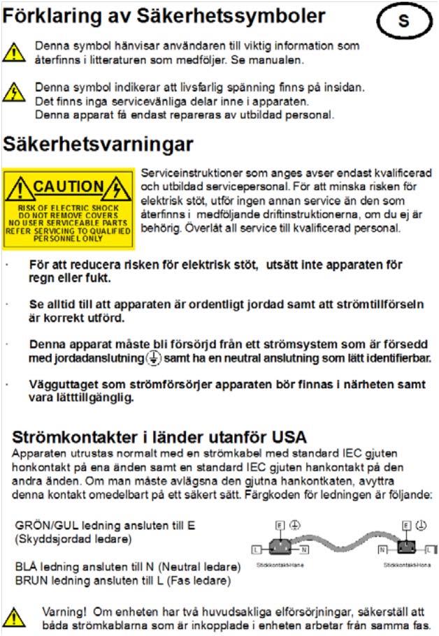
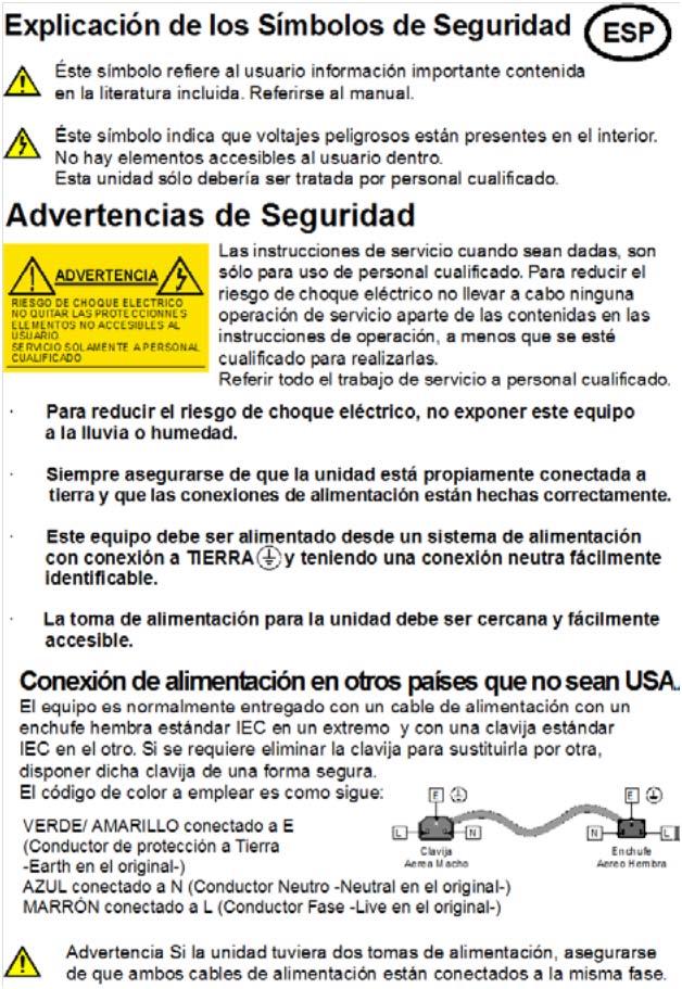
5 Safety Information Mains Power Supplies This equipment has two 3-pin IEC power sockets, one for the main power supply unit and one for the redundant power supply unit. The power supply is auto switching for input voltages in the ranges of 100 V to 240 V nominal. No voltage adjustment procedure is required. This equipment has more than one power supply. To reduce the risk of electric shock, plug each power supply into separate branch circuits employing separate service grounds. Before performing any servicing or maintenance, disconnect and isolate the unit from the mains inputs and from any product outputs. Do not operate this unit without an earth connection. Laser Safety This product operates with Class 1 laser products. Caution: Use of controls or adjustments or performance of procedures other than those specified herein may result in hazardous radiation exposure. Ventilation Although the unit is constructed to meet normal environmental requirements, ensure that there is a free flow of air at the front, rear, and sides of the unit to dissipate the heat produced during operation. Installations should be designed to allow for this. Issue 1 Rev 1 Page SAM

 Electromagnetic Compatibility of Multimedia Equipment - Emission Requirements.")
6 Safety Information Do not obstruct the ventilation holes on the right-hand side of the unit. Damage to the equipment may result. Compliance Standards This equipment conforms to the following standards: EN : 2006 Safety of Information Technology Equipment Including Electrical Business Equipment. UL1419 (4th Edition) - UL File E Standard for Safety Professional Video and Audio equipment. EMC Standards This equipment conforms to the following standards: EN 55032:2012 (Class A) Electromagnetic Compatibility of Multimedia Equipment - Emission Requirements. EN :2014 (Class A) Limits for Harmonic Current Emissions. EN :2013 Limitation of Voltage Changes, Voltage Fluctuations and Flicker in Public Low-Voltage Supply Systems. FCC/CFR 47:Part 15, Class A Federal Communications Commission Rules Part 15, Subpart B, Class A. EMC Environment The product(s) described in this manual conform to the EMC requirements for, and are intended for use in, the controlled EMC environment (for example, purpose-built broadcasting or recording studios), and the rural outdoor environment (far away from railways, transmitters, overhead power lines, etc.) E4. Warning: This equipment is compliant with Class A of CISPR 32. In a residential environment this equipment may cause radio interference. EMC Performance of Cables and Connectors Snell products are designed to meet or exceed the requirements of the appropriate European EMC standards. In order to achieve this performance in real installations it is essential to use cables and connectors with good EMC characteristics. All signal connections (including remote control connections) shall be made with screened cables terminated in connectors having a metal shell. The cable screen shall have a large-area contact with the metal shell. Issue 1 Rev 1 Page SAM
7 Safety Information Coaxial Cables Coaxial cables connections (particularly serial digital video connections) shall be made with high-quality double-screened coaxial cables such as Belden 1694 or BBC type PSF1/2M. D-type Connectors D-type connectors shall have metal shells making good RF contact with the cable screen. Connectors having indents which improve contact between the plug and socket shells are recommended. Issue 1 Rev 1 Page SAM
8 Contents Contents Information and Notices Copyright and Disclaimer Contact Details Safety Information Mains Power Supplies Laser Safety Compliance Standards EMC Standards EMC Environment EMC Performance of Cables and Connectors Introduction Description Front Panel View Rear Panel View Feature Summary Block Diagram Order Codes Technical Specification Installation Unpacking the Unit Rack Mounting the Unit Ventilation Connections Input and Output Connections Fiber Connectivity Audio Connection Pin Numbers (Option) Front Panel Features Front Panel Layout Front Panel Controls Turning the Unit On The Home Screen Video Monitoring Using the Front Panel - Basics Entering Numeric Characters from the Front Panel Entering Numeric Characters from the Rotary Control Selecting an Action Using On/Off Resetting Menu Options to Default Values Front Panel Buttons Input Output Video Audio Memory Home Convert SDR/HDR ARC Enhance System Control Lock Operation Using RollCall Issue 1 Rev 1 Page SAM
9 Contents Template Pages Setting Values Input/Output Video Processing Convert Processing ARC Audio Routing Audio Shuffle Audio Control Genlock Timecode Metadata Network Setup Operation Via Web Browser Browser-only Operations Issue 1 Rev 1 Page SAM
10 Introduction 1 Introduction 1.1 Description Kudos Pro UHD units are motion-adaptive up/down format converters for a range of applications, including: Integration of HD programming into UHDTV productions. Provision of HD simultaneous transmissions alongside UHDTV services. Mixed usage of four quadrant square-division and pixel-interleaved UHDTV content. These converters are ideal for customers who need to manage both HD and UHD content within their production or transmission workflow. 1.2 Front Panel View Rotary control for quick menu navigation Function buttons Standby button Visual confidence monitor screen Press to select menu items Home button Status indicators 1.3 Rear Panel View Ethernet 12G Fiber (option) 12G In/Out Dual PSU Reference 3G Fiber (option) SDI inputs SDI outputs Balanced AES and analog audio 1.4 Feature Summary The UHD format converter range provides the following features: Linear motion adaptive SD/HD/3G/UHDTV up/down/cross conversion at the same frame rate. Linear motion adaptive frame rate conversion available when up or down converting. 4 x SDI inputs, 4 x SDI outputs. Analog and AES audio inputs and outputs (option). 1 x 12G SDI input, 1 x 12G SDI output (option). 2 x SFP+ (option). 16-channel embedded audio processing. Dolby E guard-band alignment. Synchronization to a bi/tri-level reference. Issue 1 Rev 1 Page SAM
 and BT2020 wide color gamut support, along with video proc and powerful picture enhancement tools, including edge enhance and noise reduction. User-friendly front panel.")
11 Introduction Quad link (2SI and QSD). Rec709/2020 color. Dual PSU as standard. Automatic Aspect Ratio Conversion (AFD, VI, L23). HDR (PQ, HLG, Slog3) and BT2020 wide color gamut support, along with video proc and powerful picture enhancement tools, including edge enhance and noise reduction. User-friendly front panel. Web interface remote control. Closed caption, teletext subtitle, and timecode handling. 1.5 Block Diagram 1.6 Order Codes The following product order codes are covered by this manual: FGAFA X - UHD G UHD/HD/SD converter. FGAFA X - UHD G UHD/HD/SD converter with analog and AES audio I/O. FGAFA X - UHD1100 3G UHD/HD/SD converter (base model). FGAFA X - UHD1100 Audio 3G UHD/HD/SD converter with analog and AES audio I/O. Issue 1 Rev 1 Page SAM
12 Technical Specification 2 Technical Specification Inputs and Outputs Signal Inputs Serial Digital Inputs Input Standards 4 x 75 Ohm SD/HD/3Gb/s serial digital with embedded audio 1 x 75 Ohm UHD6G/UHD12G/HD/3Gb/s serial digital with embedded audio UHDTV1 video interfaces: Square division (4 x 1.5Gbps links) for <= 30fps Square division (4 x 3Gbps links) for > 30fps Sample interleaved SMPTE ST425-3 (2 x 3Gbps links) for <=30fps Sample interleaved SMPTE ST425-5 (4 x 3Gbps links) for > 30fps 12Gb/s UHD-4K SDI, SMPTE ST Gb/s HD-SDI, SMPTE425 level A, dual-link level B 1.5 Gb/s HD-SDI SMPTE292M/SMPTE299M Reference Audio AES (option) Audio Analog (option) Signal Outputs Serial Digital Outputs Output standards 270 Mbit/s SD-SDI SMPTE259M 1 x loop-through HDTV Tri-/SD Bi- (black and burst) SMPTE 240M/274M, with auto selection dependant on output standard Up to 4 1 balanced AES inputs via 25-way D-type 1 AES audio connector may be configured as input or output. 2 x stereo analog inputs via 25-way D-type 4 x 75 Ohm SD/HD/3Gb/s serial digital with embedded audio UHDTV1 video interfaces: Square division (4 x 1.5Gbps links) for <= 30fps Square division (4 x 3Gbps links) for > 30fps Sample interleaved SMPTE ST425-3 (2 x 3Gbps links) for <=30fps Sample interleaved SMPTE ST425-5 (4 x 3Gbps links) for > 30fps 3Gb/s HD-SDI, SMPTE425 level A, dual-link level B 1.5 Gb/s HD-SDI SMPTE292M/SMPTE299M 270 Mbit/s SD-SDI SMPTE259M Audio AES (option) Up to 4 1 balanced AES outputs via 25-way D-type 1 AES audio connectors may be configured as input or output. Audio Analog (option) 2 x stereo analog outputs via 25-way D-type Issue 1 Rev 1 Page SAM
13 Technical Specification Standards Input/Output Standards Supported i i p p p p p p p p p p p p p i i i psf psf psf psf psf p-A p-A p-A p-B p-B p-B p p p p p p-A p-A p-A p-B p-B p-B Note: Input standards are auto-detected, but may also be defined manually. see section Interface Formats SD HD 3G Level A 3G Level B 625i, 525i 720p, 1080i, 1080p 1080p 1080p 6G 2160p 2-sample interleaved ST G 2160p 2-sample interleaved ST Dual Link 2SI 2160p 2-sample interleaved ST Quad Link 2SI 2160p 2-sample interleaved ST Quad Link SQD 2160p Square Division 1.5G, 3G Issue 1 Rev 1 Page SAM
14 Technical Specification Input Capabilities Input Conn SD HD 720p (23-60) 1080i (50-60) 1080p (<=30) 3G 1080p-A 1080p-B 6G 2160p (<=30) 12G 2160 (>30) Dual Link 2160p 2SI (<=30) Quad Link 2160p 2SI (>30) SQD (23-60) SDI 1 Ch1 Ch1 SDI 2 Ch2 Ch2 SDI 3 Ch3 SDI 4 Ch4 12G SDI SFP 1 (Rx) SFP 2 (Rx) SFP 3 (Rx) SFP 4 (Rx) Output Capabilities Output Conn SD HD 720p (23-60) 1080i (50-60) 1080p (<=30) 3G 1080p-A 1080p-B 6G 2160p (<=30) 12G 2160 (>30) Dual Link 2160p 2SI (<=30) Quad Link 2160p 2SI (>30) Quad Link 2160p SQD (23-60) SDI 1 Ch1 Ch1 Ch1 SDI 2 Ch2 Ch2 Ch2 SDI 3 Ch1 Ch3 Ch3 SDI 4 Ch2 Ch4 Ch4 12G SDI 12G or 6G 3G Ch 4 Ch4 SFP 1 (Tx) Ch1 Ch1 Ch1 SFP 2 (Tx) Ch2 Ch2 Ch2 SFP 3 (Tx) 12G or 6G Ch3 Ch3 SFP 4 (Tx) 12G or 6G Ch4 Ch4 Note: Simultaneous outputs of dual/quad link and 6/12G via BNC are available only when the UHD output interface is set to 2SI/12G. SFP inputs will show as available if any module is fitted, although will only report the detection of video if an Rx module is fitted. Issue 1 Rev 1 Page SAM
15 Technical Specification Conversion Functions Modes Conversion Aspect Ratio Conversion (Manual or Auto) Audio Embedded Audio Throughput Delay SD/HD/3G/UHDTV Up, Down, and Cross Conversion Linear/Motion Adaptive AFD (SMPTE 2016), VI (RP186), WSS (L23) Each processing channel includes 16-channel embedded audio processing. PCM audio processing includes channel level gain and delay compensation, as well as pair level routing with L/R swap and phase invert feature. With frame rate conversion, the average delay is< 130ms. Note: Sync Mode (see section ) applies only when the input and output are the same format, e.g i to i. Note: The ARC feature (see section 6.4.8) is not available in UHD to UHD conversion, but is always active for UHD up/down. Audio Processing Delay Power Input voltage range (primary & secondary) Power Consumption Mechanical Temperature Range Cooling Weight Case Type Input Output Min Delay Max Delay UHD SQD UHD SQD 0.1 Min plus 1 field UHD SQD UHD 2SI <10ms Min plus 1 field UHD 2SI UHD 2SI 0.1 Min plus 1 field UHD 2SI UHD SQD <10ms Min plus 1 field UHD SQD 3G/HD <18ms Min plus 1 field UHD 2SI 3G/HD <8ms Min plus 1 field UHD SQD SD <20ms Min plus 1 field UHD 2SI SD <10ms Min plus 1 field 3G/HD UHD SQD <15ms Min plus 1 field 3G/HD UHD 2SI <7ms Min plus 1 field SD UHD SQD <16ms Min plus 1 field SD UHD 2SI <8ms Min plus 1 field Automatically tracks video processing delay. 100 to 240VAC, 47 to 63Hz, 1A, via three-pin IEC power socket 68W 0 to 40 C operating Internal fan, side venting 2.4 kg 1RU, rack mounting Dimensions 44mm x 430mm x 170mm (H x W x D) Note: The AES audio connector may be assigned as either input or output. Issue 1 Rev 1 Page SAM
16 Installation 3 Installation Important: Refer to Safety Information on page 3 before installing and connecting power to the unit. 3.1 Unpacking the Unit The unit is packed in a single cardboard box. Unpack the box carefully and check for any shortages or shipping damage. Report any shortages or shipping damage to SAM immediately. The box contains the following items: 1 x UHD converter unit. Note: Retain the product packaging. It may be required if returning the unit to SAM. 3.2 Rack Mounting the Unit Ensure that sufficient space is available for the unit. When installing the unit, place on a suitably specified and installed rack shelf and secure the unit using the front rack ears. 3.3 Ventilation Ensure that there is a free flow of air at the front, rear, and sides of the unit in order to dissipate the heat produced during operation. Installations should be designed to allow for this. Important: Do not obstruct the ventilation holes on the right-hand side of the unit. Damage to the equipment may result. Issue 1 Rev 1 Page SAM
17 Connections 4 Connections This section describes the physical input and output connections provided by the UHD range. 4.1 The rear panel accommodates a variety of different connections, depending on the model. The illustration below shows the fully loaded 12G + audio option model. Ethernet 12G Fiber (option) 12G In/Out Dual PSU Reference 3G Fiber (option) SDI inputs SDI outputs Balanced AES and analog audio 4.2 Input and Output Connections Label Description Connector 12G SDI in 12G SDI input 1 x BNC 12G SDI out 12G SDI output 1 x BNC SDI in 1, 2, 3, 4 SDI inputs 4 x BNC SDI out 1, 2, 3, 4 SDI outputs 4 x BNC Network 10/100 BaseT Ethernet connection 1 x RJ45 Reference Reference input 2 x BNC Option I/O Signal input/output 2 x dual SFP compatible AES Audio I/O (option) AES audio input/output 1 x 25-way D-type Analog Audio I/O (option) Analog audio input/output 1 x 25-way D-type Power A, B PSU inputs (primary, secondary) 2 x 3-pin IEC Note: If one of the reference connectors is not in use, it must be fitted with a 75 Ohm BNC terminating plug. If not terminated correctly, genlock performance may be degraded. Note: The option sockets allow for up to two dual Small Form Factor Pluggable (SFP) transceiver modules. The SFP modules can be used to add optional fiber connectivity, or optional I/O using HD BNC connectors. Issue 1 Rev 1 Page SAM
18 Connections 4.3 Fiber Connectivity A dual fiber port is available as an option. The port can be configured as one of the following: Dual HD/3G receiver (RX/RX) Single HD/3G/12G receiver (RX) Dual transmitter (TX/TX) Transceiver (RX/TX) Not fitted If no fiber option is fitted on the rear panel, do not remove the safety covers from the option slots. Issue 1 Rev 1 Page SAM
19 Connections 4.4 Audio Connection Pin Numbers (Option) AES audio and analog audio support are available as an option. Connection is via 25-way D-type. Balanced AES audio I/O connectors can be configured as either input or output. Channel Analog Audio I/O 25 Way D-Type Pin 25 Way D-Type Connector Channel AES Audio I/O 25 Way D-Type Pin Chassis 1 Chassis 1 GND1 14 GND1 14 Analog Out 4+ 2 Port 8+ 2 Analog Out 4-15 Port 8-15 Analog Out 3+ 3 Port 7+ 3 Analog Out 3-16 Port 7-16 GND2 4 GND2 4 GND3 17 GND3 17 Analog Out 2+ 5 Port 6+ 5 Analog Out 2-18 Port 6-18 Analog Out 1+ 6 Port 5+ 6 Analog Out 1-19 Port 5-19 GND4 7 GND4 7 GND5 20 GND5 20 Analog In 4+ 8 Port 4+ 8 Analog In 4-21 Port 4-21 Analog In 3+ 9 Port 3+ 9 Analog In 3-22 Port 3-22 GND6 10 GND6 10 GND7 23 GND7 23 Analog In Port Analog In 2-24 Solder Pin Side Port 2-24 Analog In Port Analog In 1-25 Port 1-25 GND8 13 GND8 13 Issue 1 Rev 1 Page SAM
20 Front Panel Features 5 Front Panel Features The front panel provides a user-friendly interface for complete control of the unit. Various buttons provide easy access to the unit s features. 5.1 Front Panel Layout Rotary Control for fast scrolling through menus Function/numeric entry buttons Standby Function/numeric entry buttons Screen for visual confidence monitoring Press to select menu items Home button Status indicators 5.2 Front Panel Controls Item Display Rotary control Description Shows either the output video or the menu options. Scrolls through the menu lists, selects menu options, and adjusts values. Rotate clockwise or anti-clockwise to scroll down or up through a menu list or to adjust values on a menu option. Press to select a menu option or confirm changes. Press and hold to jump to the Back option under a menu list. Press and hold when entering parameter values to return the parameter to default value. When at the Home screen, press to toggle between status display and video monitoring. Home button Function/Numeric buttons Standby button Rotate to display the 4 UHD quadrants on the front panel screen when using SQD input. Press to return to the default Home screen at any time. When on the Home screen, press the Home button to toggle between status display and video monitoring. Provide direct access to menus. Turns the unit on or puts the unit into standby mode. Press and hold to turn the unit on. Press and hold to put the unit into standby mode. When the unit is in standby mode, the corresponding PSU LEDs are illuminated red. Issue 1 Rev 1 Page SAM
21 Front Panel Features Item Control Lock button PSU Status LEDs Control Status LEDs Description Press to lock the front panel controls. Press and hold for three seconds to unlock the front panel controls. Shows the status of the dual PSUs. PSU A illuminated green: PSU A (primary) in use. PSU B illuminated green: PSU B (secondary) in use. PSU illuminated red: unit in standby (power saving) mode. Shows the monitoring status. Local illuminated: local control enabled. Remote illuminated: browser-based UI may be in use. Issue 1 Rev 1 Page SAM
22 6 The UHD range can be controlled directly, using the front panel hardware buttons, or remotely, using a software UI in a browser window. All operations are possible from either interface. The operating instructions given here focus on operation via the front panel. Operation via the browser-based UI follows the same basic control sequences, and should be self-explanatory. 6.1 Turning the Unit On Press and hold the Standby button. The PSU LED turns green and the splash screen is shown on the display. After a short period, the Home screen is displayed. 6.2 The Home Screen The Home screen shows the following status information: Unit name; IP address; Input and output standard; Reference standard. The Home screen can be displayed at any time by pressing the Home button. Note: If no controls are used, the unit will automatically return to the Home screen after a few minutes Video Monitoring To view the output video on the front panel monitor screen, first press the Home button to return to the Home screen. From here, pressing the rotary control or the Home button will toggle between Home screen and video monitor. Issue 1 Rev 1 Page SAM
23 6.3 Using the Front Panel - Basics The front panel buttons provide access to the UHD control menus. Turn the rotary control clockwise to scroll down through a menu list, or anti-clockwise to scroll up. When on the required menu item, press the rotary control to select it. When a menu option that offers adjustment is selected, such as audio gain, the value can be adjusted by turning the rotary control. This allows control for fine-tuning values in small increments. When the desired value has been entered, press the rotary control to set the value. Select Back at the bottom of each menu page go back up a level, or simply select another front panel button to change to a different menu. To return to the Home screen, press the Home front panel button. Note: Press and hold the rotary control for a few seconds to jump to the Back option when in any menu list. To reset any parameter back to its default value: from the parameter selected, press and hold the rotary control for a few seconds Entering Numeric Characters from the Front Panel Fields requiring numeric input are displayed with a cursor. Use the rotary control to move the cursor to the required position, then press the appropriate front panel button to enter a value. Press the rotary control when complete Entering Numeric Characters from the Rotary Control Where a parameter may be set from a range of values with only certain specific steps, numeric entry is via the rotary control: 1. Press the rotary control to show the current value, e.g. contrast. 2. Rotate the control clockwise to increment the value by each step, e.g. contrast increments in steps of 0.2 db. Likewise, rotate the control counter-clockwise to decrement the value. 3. The value will not pass beyond its defined range, e.g. valid contrast adjustments are from -6.0 db to 6.0 db. 4. To return to default, press and hold the rotary control. The values are reset. 5. When the value is set as required, press the rotary control again to confirm and return to the last menu Selecting an Action Using On/Off Where an action is available to turn a feature on or off using the rotary control: 1. Scroll the rotary control to the required item, e.g. Video > Enable proc amp. 2. Press the rotary control to view the current status, e.g. On. 3. To change the action, turn the rotary control until the desired action is visible, e.g. Off. Press the rotary control to select. Issue 1 Rev 1 Page SAM
24 6.3.4 Resetting Menu Options to Default Values To reset a menu option to its default value: With the menu option selected, press and hold the rotary control for a few seconds. Issue 1 Rev 1 Page SAM
25 6.4 Front Panel Buttons Input Press Input to specify a video input source. Available functions are: Menu Option Input select Operation Choose from: SDI 1 SDI 2 SDI 3 SDI 4 (SD, HD and 3G support only) Note: Audio and metadata are processed from Input 1 only. Audio and metadata on Inputs 2-4 are ignored. Quad SDI input - Selects UHD input via BNC inputs 1-4 (Quad link) or inputs 1-2 (Dual link). 12G SDI UHD - Selects 12G BNC Input. Accepts HD, 3G, UHD 6G and UHD 12G. SFP1 (if RX module fitted to slot 1). Accepts SD, HD and 3G. SFP2 (if RX module fitted to slot 2). Accepts SD, HD and 3G. SFP3 (if RX module fitted to slot 3). Accepts HD, 3G. SFP4 (if RX module fitted to slot 4). Accepts HD, 3G, UHD 6G and UHD 12G. UHD Interface SDI 1-4 std status The currently selected input is highlighted. Input format setting for Dual/Quad link interface only (BNCs 1-4). Choose from: Auto (default) - use embedded PID to identify Sample Interleaved format. If ST425-3/5 PID (0x96,0x97,0x98) is not detected, Square Division is enabled. SQD - manually selects Square Division. 2SI - manually selects ST425-3/5 format. Reports interface standard on each input, e.g p-A, i, etc. Loss = missing input. SDI 1-4 conn status Reports UHD status of SDI Inputs 1-4. UHD std status Valid values are: None: No UHD connection detected. OK: UHD connection present. Reports interface standard on each input, e.g p-A, i, etc. Loss = missing input. Issue 1 Rev 1 Page SAM
26 Menu Option Operation UHD conn status SDI Inputs 1-4 Valid values are: None: UHD has not been detected. Inconsistent: The detected input is a possible UHD format but does not match the other inputs. 2SI input [n]: Two-Sample Interleaved UHD has been detected. n indicates the channel number contained in the PID. Where this does not match the input number, it will be necessary to reconnect the inputs in the correct order. SQD: Square Division UHD has been detected. Error: [Inputs 2-4 only]. Indicates a timing error relative to input 1. UHD Inputs (Quad SDI, 12G SDI and SFP 3) 12G BNC std status 12G BNC conn status SFP 1-4 std status Valid values are: OK None Reports interface standard on each input, e.g p-A, i, etc. Loss = missing input. Reports interface standard on each input, e.g p-A, i, etc. Loss = missing input. Reports interface standard on each SFP, e.g p-A, i, etc. Loss = missing input. Note: The UHD range automatically detects the input standard. Issue 1 Rev 1 Page SAM
27 6.4.2 Output Press Output to make settings and adjustments to the video output signal. Available functions are: Menu Option Out std-sd/hd in (Output standard with SD/HD input) Operation Use this control to set the required output standard when the input is SD, HD or 3Gbps. Note: p-30p outputs are carried on 4 x 1.5Gbps links in Square Division, or 2 x 3Gbps Level C links (outputs A1 and A2) in Sample Interleaved p-60p outputs are carried on 4 x 3Gbps links. Single-link 12G output is available via the 12G BNC connector (see 2SI Mode, below). Out std-uhd in (Output standard with UHD input) Scroll through the list until the required output standard is reached, then press to select. Press the rotary control again to confirm and return to the Output menu. Use this control to set the required output standard when the input is UHD. Scroll through the list to the required output standard, then press to select. Press the rotary control again to confirm and return to the Output menu. Current out std UHD interface 2SI Mode UHD 2SI PID Note: When input and output are both UHD, the output frame rate will follow the input frame rate. Displays the output standard currently applied to the spigot. Selects the output format. Choose from: 2SI: Sample-interleaved format. Allows 6G/12G output via the 12G BNC. SQD (quad link): Square division format. Available only via output BNCs 1-4 and SFPs 1-4. When selected, the 12G output is not available as the 12G BNC is a duplicate of link 4. When UHD Interface is set to 2SI, the output available on SFP3/4 and the 12G BNC can be selected as either 12G or Quad-link fibre: 12G - 12G BNC and SFP3/4 output UHD in 12G single-link format. Quad SFP - SFP3/4 are set to output 3G quad-link channels 3 & 4 (channels 1 & 2 are output from SFP1/2). The 12G BNC outputs a copy of quad-link channel 4. Sets the embedded Payload ID for Sample Interleaved. Choose from: UHD - some quad link monitors may not operate with UHD PID. In these cases, select HD/3G. Note that 12G monitors will require a UHD PID. HD/3G Issue 1 Rev 1 Page SAM
28 Menu Option UHD ANC embed Legalization Test pattern Operation Sets whether ANC (VANC + HANC) data is inserted on all links or just link 1. For non-uhd output standards, ANC is inserted on all output BNCs. The Legalizer ensures that the output video stays within the legal RGB gamut limit, making it suitable for the broadcast signal chain. To achieve this, the legalizer reduces the gain equally on all channels. Anything in the RGB space above the selected value (e.g. 700mV) is scaled down to that value. Anything in the RGB space below 0mV is clipped to 0mV. This is a good compromise between minimizing hue change and raising apparent brightness. Legalizer choices are: Off 700mV 721mV 735mV 746mV Choose from: Off Black Ramp Bars Video Press Video for controls allowing various types of signal processing to be applied to the signal being converted. Available functions are: Process Amplifier (Proc Amp) Allows video inconsistencies to be corrected. Menu Option Enable proc amp Black level Contrast Saturation Y gamma Color correct Operation Select On to activate Proc Amp functions. Adjusts the black level from -100mV to +100mV in 0.8mV steps. Default is 0mV. Adjusts the contrast from -6dB to +6dB in 0.2dB steps. Default is 0dB. Adjusts the color saturation from -6dB to +6dB in 0.2dB steps. Default is 0dB. Adjusts the luma gamma from 0.4 to 1.7 in 0.1 steps. Preset is 1.0. Allows corrections to be made to the video color. See section Issue 1 Rev 1 Page SAM
29 Color Correct Menu Option Enable correct Red lift Red gain Green lift Green gain Blue lift Blue gain Operation Select On to activate Color correct functions. Red channel offset can be adjusted from -200mV to +200mV in steps of 0.8mV. Default is 0mV. Red gain can be adjusted from -6dB to +6dB in steps of 0.2dB. Default is 0dB. Green channel offset can be adjusted from -200mV to +200mV in steps of 0.8mV. Default is 0mV. Green gain can be adjusted from -6dB to +6dB in steps of 0.2dB. Default is 0dB. Blue channel offset can be adjusted from -200mV to +200mV in steps of 0.8mV. Default is 0mV. Blue gain can be adjusted from -6dB to +6dB in steps of 0.2dB. Default is 0dB Audio The Audio button allows you to access audio routing, shuffling and control menus. Note: Embedded audio is supported by all models. Analog and AES audio are available only if the audio option has been purchased. Terminology in this section: Source audio (input pairs or channels) refers to audio associated with the incoming source material, which could be embedded audio, balanced AES (audio option only) or analog audio (audio option only); Process pairs or channels (sometimes abbreviated to process pr in the menus) refer to audio processing channels, to which input audio pairs may be assigned; Output pairs or channels refer to audio coming from the processing channels which is routed to the unit outputs. Output audio can be embedded, balanced AES (audio option only) or analog (audio option only). Audio menus are: Audio routing Audio shuffle Audio control Analog I/O (audio option only) AES I/O (audio option only) In pair status Out pair status These are described in the sections below. Issue 1 Rev 1 Page SAM
30 Audio Routing To select the audio source to be passed to each audio processor, first select the process channel from the list of process pairs (1 to 8), then select the source audio pair from the list below to assign to the chosen channel. Source Audio Available Choices Embedded audio Embedded 1-8 AES AES 1-8 Analog Analog 1-2 For example, to use source audio from SDI Embedded 3 in audio processing channel 2: Audio Shuffle Press the Audio button on the front panel. Scroll to Audio routing then press the rotary control. Scroll to Process pair 2 in the process pair list, then press the rotary control. Scroll to Embedded 3 in the input pair list, then press the rotary control. Press the rotary control again to return to the previous menu. Scroll to the Back menu item and press the rotary control to return to the Audio menu. Audio shuffle allows routing from each process pair to the output. Facilities to invert audio phase and insert tone or silence are also available from this menu. Assigning an output from a processing channel Select the required output channel from the list of channels (Channel 1 to Channel 16). A menu of choices for the selected channel is displayed. For example, if Channel 1 is selected, the menu choices are: Audio Shuffle Available Choices Ch [x] source Select process channel from 1 to 16. Invert phase Ch [x] output Causes the phase of left and right audio channels to be inverted. This is useful for dealing with input audio discrepancies. Choices are: Off On (default) Choices are: Use routing (default). Tone (inserts tone into the chosen audio channel). Silence (mutes the chosen audio channel). Selecting Ch [x] source displays the available process pairs. From the list of process channels, choose the process channel to route to the chosen output channel (1 to 16): Issue 1 Rev 1 Page SAM
31 Example 1: To assign process channel 2 to output SDI embedded channel 8: Press the Audio button on the front panel. Scroll to Audio shuffle then press the rotary control. Scroll to Channel 8 in the output pair list, then press the rotary control. Scroll to Ch 8 source in the list, then press the rotary control. Scroll to 2 in the list, then press the rotary control. Scroll to the Back button, then press the rotary control again to return to the Audio shuffle main menu. Example 2: To invert phase for a chosen audio channel: Select the required output channel from the list of channels (Channels 1 to 16) Turn Invert phase to On. Note: Phase invert is available only for PCM audio. Note: The Audio Shuffle menu allows any configuration of audio channels to be routed to the output. Illegal combinations will result in the output being forced to silence. If both audio channels of an audio pair have been derived from non-pcm audio channels, there are two possible states, Non-PCM or Forced silence. To be recognized as valid non-pcm (N), both channels must: Have come from the same input pair; Have the left and right channels the correct way round; Not have the phase inverted. A failure of any of these conditions will cause the pair to be muted and the status to be reported as Forced silence Audio Control Audio control adjusts the audio on each processing channel. Audio Control Audio gain Available Choices Audio gain can be adjusted from -18dB to +18dB in steps of 0.1dB. Default is 0dB. Select the required output channel from the list of channels (Out Ch 1 to Out Ch 16), then adjust the gain using the rotary control. Alternatively, use the Master control to adjust the gain for all channels at once: individual channel gain offsets are preserved and limited at the maximum and minimum gain values. Issue 1 Rev 1 Page SAM
32 Audio Control Pair delay Available Choices Pair delay can be adjusted for each of the eight audio channel pairs. The adjustment range is -40ms to +200ms in 1ms steps. The default value is 0ms. Pair delay status Video delay status Dolby E align Tone freq To adjust delay offset, first select the process pair from the process pair list (Process pair 1 to Process pair 8) then select the required delay offset using the rotary control. Alternatively, use the Master control to adjust the delay for all pairs at once: individual pair delay offsets are preserved and limited at the maximum and minimum delay values. With delay set to zero, the audio will be co-timed with the video. Shows the total delay per pair in ms. Select the required pair from the audio status list (Pair 1 total to Pair 8 total) to view the total delay applied to that pair. Shows the current total video delay through the unit in ms. Dolby E alignment offset can be selected from -10 lines to +10 lines in steps of 1 line. Default is 0 lines. Tone frequency can be selected from 100Hz to 10000Hz in steps of 100Hz. Default is 1000Hz. Note: Global delay is applied to all channels. Individual pair delays are added/subtracted from this delay. Pair delay is added instantaneously and will produce an audible disturbance. Global delay is added or subtracted at the rate of 2ms/s, and does not produce an audible disturbance. Allow time for the global delay to settle to the desired value. The maximum audio delay (video processing delay + added audio delay) is limited to 260ms Analog I/O (audio option only) The Analog I/O menu allows output audio pairs to be mapped to the outgoing analog pairs. Analog I/O Out 1 source Out 2 source Out 1 level Out 2 level Available Choices Ch1 Pair 1 to Pair 8 Ch2 Pair 1 to Pair 8 Ch1 Pair 1 to Pair 8 Ch2 Pair 1 to Pair 8 Adjusts the analog audio DAC level for analog audio output Pair 1, from 12dB to 24dB in steps of 0.5dB. Default is 18dB. Adjusts the analog audio DAC level for analog audio output Pair 2, from 12dB to 24dB in steps of 0.5dB. Default is 18dB. Issue 1 Rev 1 Page SAM
33 Analog I/O In 1 headroom In 2 headroom Available Choices Adjusts the analog audio ADC headroom level for analog audio input Pair 1, from 12dB to 24dB in steps of 0.5dB. Default is 18dB. Adjusts the analog audio ADC headroom level for analog audio input Pair 2, from 12dB to 24dB in steps of 0.5dB. Default is 18dB AES I/O (audio option only) Balanced AES audio I/O is available via 25-way D-type connectors, configurable as input or output. See section 4.3 for AES audio connector pin numbers. Each AES port can be selected in turn from the AES port list (Port 1 to Port 4), and can then be assigned as: Input (default). Any of output Ch1 Pair 1 to Pair 4, Ch2 Pair 1 to Pair Input Pair Status Options available for each input pair: Source Audio Press the rotary control to view the input pair status: PCM: audio is PCM. Loss: no audio detected. Data: data detected on audio channel. DolbyE: DolbyE audio detected Out Pair Status Status information is available for each output pair from the output pair list (Output pair 1 to Output pair 8). PCM Muted Test tone Non-PCM Forced silence Options Available Embedded audio Embedded 1-8 AES AES 1-8 Analog Analog 1-2 Issue 1 Rev 1 Page SAM
34 Note: The Audio Shuffle menu allows any configuration of audio channels to be routed to the output. Illegal combinations will result in the output being forced to silence. If both audio channels of an audio pair have been derived from non-pcm audio channels, there are two possible states, Non-PCM or Forced silence. To be recognized as valid non-pcm, both channels must satisfy 3 conditions: have come from the same input pair; have the left and right channels the correct way round; not have the phase inverted. Failure of any of these conditions will cause the pair to be muted and the status to be reported as Forced silence Memory The Memory button allows the unit to be reset to one of 10 previously saved configurations. Available functions are: Menu Option Memory Select Recall Memory Save Memory Clear Memory Reset to Defaults Factory Reset Operation Press to select a memory to recall, save or clear. Press to load the contents of the selected memory. Press to save current configuration to the selected memory. Please note network settings are NOT saved. Press to clear the selected memory. All controls are reset to their default values, except for network configuration and IP addresses. All controls are reset to their default values, including network configuration and IP addresses Home Causes the Home page to be displayed Convert Convert provides a set of solutions to enable optimized conversion of film-originated content. Film-originated content may be transported by standards supporting the original film frame rate, such as p. Film-originated content may also be packed into interlaced standards using a rule-based method to map source frames to interlaced fields. In this case, the interlaced standard's content is described as having a film cadence. In order to perform high quality conversion of film-originated content, the cadence must be identified and used to adapt the interpolation process. Film mode (see section ) also permits the synthesis of film cadence in the output Clean cut Clean cut processing detects scene changes and prevents interpolation across the cut. Only permitted if film cadence is off. Default = On. Issue 1 Rev 1 Page SAM
35 Film mode Use Film mode if input is interlaced (1080i or 525 or 625) and contains film-originated content. This adjusts the conversion aperture to give maximum vertical bandwidth. Default = Off. Note: This mode is relevant only for film originated content where the cadence is carried in an interlaced format. Where film-originated content is carried in a progressive format, Film mode should not be used Input cadence The Input cadence menu allows the user to define any cadence associated with the input video. Status Displays the current cadence. Enable If the input content is film-originated with a 2:3 cadence, or simulates film-originated content, Enable should be set to On. Otherwise, it should be set to Off. This feature is not available when converting UHD 59p to UHD 23p, or UHD 60p to UHD 24p. Default = Off. Example 1: Input UHD 59p (with embedded 3:2 cadence), Output p. Input frame sequence: A, A, B, B, B, C, C, D, D, D When cadence is On the output frame sequence will be: A, B, C, D When cadence is Off the output will be a linear frame rate conversion. 2:3 Source When set to Automatic (default) the input cadence will be determined by the cadence detection circuit. This feature is useful when the source material contains mixed cadences.when set to Input timecode, the user defines the relationship between timecode and the 2:3 sequence. This feature is useful when the source material contains known continuous 2:3. This setting removes any uncertainty that may be associated by use of the sequence detector (automatic mode). 2:3 Start hour This control allows the user to define the position of timecode when the 2:3 sequence begins. The assumption is made that the start of the 2:3 sequence is aligned with the start of program and under normal working practices, that the start of program is coincident with an integer hour value. This control is active only when 2:3 is set to Input timecode and Drop-Frame Timecode is present. For non-drop Frame Timecode sources this control has no effect. Control is available from 1 hour to 23 hours, in steps of 1 hour. The default is 1 hour. Issue 1 Rev 1 Page SAM
36 Insert cadence Allows the insertion of film cadence on the output. Output frame rate must be 50, 59 or 60Hz. For all other output frame rates, cadence processing is automatically disabled. Example 1: Input p, Output UHD 59p. Input frame sequence: A, B, C, D When cadence is On the output frame sequence will be A, A, B, B, B, C, C, D, D, D When cadence is Off the output will be a linear frame rate conversion. Example 2: Input p, Output UHD 50p Input frame sequence: A, B, C, D When cadence is On the output frame sequence will be: A, A, B, B, C, C, D, D When cadence is Off the output will be a linear frame rate conversion. Enable If the output content is required to have a film cadence associated with it, Enable should be set to On. Default = Off 2:3 Source If the output is 59Hz (60Hz) and a 2:3 cadence style is selected, this control allows the sequence to be locked to output timecode. When set to Free run (default) the output 2:3 cadence starting point is not defined. The output will have continuous 2:3, but may vary from conversion to conversion. When set to Output timecode, the user defines the point where the 2:3 sequence starts relative to timecode. 2:3 Start hour This control allows the user to define the starting position of the 2:3 sequence with respect to timecode. It is active only when 2:3 is set to Output timecode and the Timecode generator is set to Drop-Frame, or, when following input timecode, the source has Drop-Frame Timecode present. When operating with non-drop Frame Timecode this control has no effect. Control is available from 1 hour to 23 hours, in steps of 1 hour. Default is 1 hour. Issue 1 Rev 1 Page SAM
37 Colorimetry Select Colorimetry to display the Colorimetry menu. Available functions are: Menu Option Input colorimetry Gamma Output colorimetry Operation Input colorimetry setting for HD, 3G and UHD. SD is fixed at BT.601. Colorimetry in use is reported as shown:. Auto - Sample interleaved: use embedded PID to identify colorimetry. Square Division: selects BT.709. BT.709 BT.2020 Sets the gamma used in the color conversion process. A gamma of 2.0 gives a better color match between 2020 and 709 cameras, while 2.4 gives a better color match between 2020 and 709 displays. See ITU-R BT.2087 for more information. Choose from: Sets the output color standard for HD, 3G and UHD. Colorimetry in use is reported as shown: Follow Input: Output colorimetry will be the same as the input colorimetry (as detected or forced). BT.709 BT SDR/HDR The SDR/HDR menu allows HDR parameters to be configured. HDR adjustments are available for some conversions only: SDR Out HLG Out PQ Out S-Log3 Out SDR In HLG In Clip PQ Level (out) PQ In Clip PQ Level (in) 3 PQ Level (out) 2 Clip 1 S-Log3 In Clip Clip PQ Level (out) Notes: 1. A clip is applied for PQ levels (in) beyond 4000cd/m 2. Inputs graded at 4000cd/m 2 or less will not be clipped. 2. Where the selected PQ level (out) is less than the incoming PQ level, soft clipping is applied as recommended in BT Use the PQ Level control to set the grading level of the incoming PQ signal. Setting the PQ level to 10k when the content is graded at 1k will result in a low-brightness output. Issue 1 Rev 1 Page SAM
38 Input Format Input gamma is set manually. Select from: SDR HLG PQ S-log Output Format Clip Select the output format to be used. Select from: SDR HLG PQ S-log3 With some HDR conversions, the maximum supported output level is lower than the source level. The Clip tool is provided to address this. Select from: PQ Level Hard - High brightness levels not supported in the selected output format are hard clipped to the maximum supported brightness level. Soft - Brightness levels close the maximum supported in the selected output format are progressively attenuated to avoid an abrupt cut-off. Soft clipping is a non-reversible process. Sets the grading level (L w ) of the input (PQ > HLG) or output (PQ > PQ). Select from: 1k (1000cd/m 2 ) 2k 4k 10k (10000cd/m 2 ) See SMPTE ST 2084: Dynamic Range Electro-Optical Transfer Function of Mastering Reference Displays for more information on PQ SDR Enhance When converting SDR to any HDR mode, automatically increases the brightness of SDR content near peak white. Select from: Off - SDR is converted into HDR format without alteration. Low - High-brightness content is slightly increased in level. Medium - High-brightness content is increased in level further. High - High-brightness content is significantly raised in level. Issue 1 Rev 1 Page SAM
39 6.4.9 ARC Click ARC (Aspect Ratio Control) to specify the aspect ratio of a picture from a range of options, or to adjust the size and position of the picture manually Sync Mode The Sync mode control reduces processing latency if there is no ARC (same format input to output, i.e. the unit is operating as a synchronizer). This gives the lowest latency. Options are: Off (default): normal operation. The ARC controls will function. On: If scaler features are inactive (no aspect ratio conversion) and Sync mode enabled, the scaler is bypassed, so reducing the processing latency. It is possible to bypass the scaler only when up-converting 1080p to UHD, down-converting UHD to 1080p or synchronizing (same standard/uhd format in and out). In all other modes the scaler is active and this control will have no effect on latency. The Vertical Filter controls are disabled when Sync Mode is active Signalling Detected Displays the currently detected signalling Post Scale The Post scaling control enables the size and position of the picture to be adjusted manually. Menu Option Post scale enable Operation Off (default) On - Enables manual adjustment of aspect ratio. Size Note: These controls do not operate in UHD to UHD mode. Adjusting the picture size in any down or cross-conversion mode can increase the amount of visible alias. To avoid this it is recommended that the Horizontal and Vertical filters are set to Narrow 1. Adjusts the size of the whole output image while maintaining the aspect ratio. Range is 80% to 120% in steps of 1%. Default is 100%. Aspect Adjusts the aspect ratio of the output image. Range is 70% to 150% in steps of 1%. Pan Default is 100%. Adjusts the horizontal position of the output image. Range is -50 to +50 pixels in steps of 1 pixel. Default is 0 pixels. Tilt Adjusts the vertical position of the output image. Range is -50 to +50 lines in steps of 1 line. Default is 0 lines. Issue 1 Rev 1 Page SAM
40 Scaler Config The Scaler offers preset controls for management of the aspect ratio. The following controls are available: Scaler Presets Use presets: Enables all presets SD input is 702: Use for SD incoming content that uses a 702 sample line rather than a 720 sample line. SD output is 702: Generates SD output with a 702 sample active line. Up convert: Sets the SD to UHD aspect ratio conversion. Available up convert presets are: From (SD) To (UHD) 4:3 16:9 vcrop (default) 4:3 4:3 PB 16:9 LB 16:9 16:9 An 16:9 14:9 LB 14:9 PB 14:9 PB 16:9 vcrop 4:3 PB 16:9 vcrop 4:3 PB 14:9 PB vcrop LB = Letterbox, PB = Pillarbox, Vcrop = Vertical Crop, An = Anamorphic Down convert: Sets the UHD to SD aspect ratio conversion. Available down convert presets are: From (UHD) To (SD) 16:9 4:3 hcrop (default) 16:9 16:9 LB 16:9 16:9 An 4:3 PB 4:3 14:9 PB 14:9 LB 14:9 PB 16:9 vcrop 4:3 PB 16:9 vcrop 4:3 PB 14:9 PB vcrop LB = Letterbox, PB = Pillarbox, Hcrop = Horizontal Crop, An = Anamorphic SD/HD Cross convert: Sets the SD to HD aspect ratio conversion. Available cross convert presets are: From (SD) To (HD) 4:3 16:9 vcrop 4:3 4:3 PB Issue 1 Rev 1 Page SAM
41 From (SD) To (HD) 16:9 LB 16:9 16:9 An 16:9 14:9 LB 14:9 PB 16:9 4:3 hcrop 16:9 16:9 LB 16:9 16:9 An 4:3 PB 4:3 14:9 PB 14:9 LB 16:9 LB 4:3 hcrop 16:9 LB 16:9 An 16:9 LB 14:9 LB 16:9 An 4:3 hcrop 16:9 An 16:9 LB 16:9 An 14:9 LB 14:9 PB 16:9 vcrop 4:3 PB 16:9 vcrop 4:3 PB 14:9 PB vcrop LB = Letterbox, PB = Pillarbox, Hcrop = Horizontal Crop, An = Anamorphic In Config Configures the unit to respond to aspect signaling control. If input signaling is not present, Force input format (see below) can be used. Signaling Src When an SD source contains more than one style of signalling, select the appropriate item: SMPTE 2016 (default) L23 ETSI L23 AFD VI SMPTE VI AFD Alternate Center Cut Alternate center cut is Off by default. When off, behavior on receipt of certain specific AFD codes ignores protected regions. When Alternate center cut is On, the ARC behavior for these six specific codes will be to remove any black bars and also remove the gray bars that will leave the Alternative Center. The Alternative center will therefore be stretched to fit the screen so that the whole white area fills the screen. This will override Fit to width, 14:9 and Fit to height settings, so that all three give the same output result. It also overrides the SD Output format control (Anamorphic or Normal). See SMPTE ST :2009 Format for Active Format Description and Bar Data, pages 7-9. Behavior with Alternate center cut on and off is shown in the table below: Issue 1 Rev 1 Page SAM
42 AFD Format Interpretation with Alt Center Cut = Off Interpretation with Alt Center Cut = On 4:3 AFD 13 4:3 4:3 Alt 14:9 4:3 AFD 14 16:9 LB 16:9 LB Alt 14:9 4:3 AFD 15 16:9 LB 16:9 LB Alt 4:3 16:9 AFD 13 4:3 PB 4:3PB Alt 14:9 16:9 AFD 14 16:9 16:9 Alt 14:9 16:9 AFD 15 16:9 16:9 Alt 4:3 Force in format Off (default) On - Forces the input format to that selected below. Will be active when input signalling is not present. SD in format For SD inputs, manually select forced format from the list: Normal - use default aspect ratio 16:9 anamorphic - horizontally squeezes a widescreen image to fit a standard 4:3 aspect ratio 16:9 letterbox - preserves the original aspect ratio of film shot in a widescreen 16:9 aspect ratio, with bars visible at the top and bottom of the screen. 14:9 letterbox - preserves the original aspect ratio of film shot in a widescreen 14:9 aspect ratio, with bars visible at the top and bottom of the screen. HD/UHD in format For HD/UHD inputs, manually select a format to force: Normal (default): use default aspect ratio 14:9 pillarbox: preserves the original aspect ratio of HD content with a 14:9 aspect ratio, with bars visible at the sides of the screen. 4:3 pillarbox: preserves the original aspect ratio of HD content with a 4:3 aspect ratio, with bars visible at the sides of the screen. Out config Convert scaling Fit to height: Scales the image to fit the height of the screen while maintaining the aspect ratio. Fit to width: Scales the image to fit the width of the screen while maintaining the aspect ratio. 14:9: Can scale either a 4:3 image for viewing on a 16:9 screen, or a 16:9 image for viewing on a 4:3 screen. This is a compromise in order to maintain the aspect ratio of the image, but will crop some of the image in the process (top and bottom when viewing 16:9, and left and right when viewing 4:3). SD out format Normal (default): Use default aspect ratio Anamorphic: Horizontally squeezes a widescreen image to fit a standard 4:3 aspect ratio. Issue 1 Rev 1 Page SAM
43 Out signalling Controls the signalling defined on the output. SMPTE 2016 Uses SMPTE 2016 signaling. Available controls are: ST2016 mode - Auto: automatically sets the conversion based on a combination of the input and output standards. Pass: passes SMPTE 2016 information through the unit unchanged. Force: forces the conversion specified on the output. Delete: deletes SMPTE 2016 information from the output signal. Out line - Selects the output line on which SMPTE 2016 information is placed. Out line status - Displays the line number on which SMPTE 2016 information is placed. Note: In the SD domain, take care to avoid a line clash if embedded VITC and SMPTE 2016 are both enabled. In the event of both VITC and SMPTE being required: For SD 625 signals, SMPTE2016 is relocated to the line before the VITC line, i.e. if VITC is at default 19 and 21, SMPTE2016 will be placed on either 18 or 20 respectively when there is a clash. For SD 525 signals, SMPTE2016 is relocated to the line between the two VITC lines, i.e. if default VITC is on lines 14 and 16, SMPTE2016 will be placed on line 15 in the event of a clash Video Index Configures Video Index (VI) signaling. Available controls are: Control Options VI mode Auto (default): Automatically sets the conversion based on a combination of the input and output standards. Pass: Passes VI information through the unit unchanged. Force: Forces the conversion specified on the output. Delete: Deletes VI information from the output signal. Out format SMPTE (default): Outputs Video Index information according to SMPTE RP186. AFD: Outputs Video Index information according to ARDSPEC1 VI pass data Off (default): VI data other than coded frame and AFD are blanked. On: User data from the source VI are passed from the input to the output. Issue 1 Rev 1 Page SAM
44 Line 23 Configures Line 23 (L23) signaling. Available controls are: Control Options L23 mode Auto (default) - Automatically sets the conversion based on a combination of the input and output standards. Pass - Passes L23 information through the unit unchanged. Force - Forces the conversion specified on the output. Delete - Deletes L23 information from the output signal. L23 out format ETSI (default) - Outputs L23 information according to ETSI EN v In line AFD - Outputs L23 information according to West Country TV/HTV/Central TV L23_SPEC.doc Selects the input line from which the L23 information is read. The range is from line 10 to line 23 in one-line steps. Default = line 23 Out line Selects the output line on which L23 information is placed. The range is from line 10 to line 23 in one-line steps. Default = line 23 Out line status Displays line number of where the signaling is placed. Force AFD user bits Off (default). On - Enables up to four user-defined bits to be inserted. AFD user bits value From 0 to 15 in steps of 1. Preset = Force mode Inserts specific signaling codes regardless of the source aspect ratio. SMPTE 2016: When enabled, inserts valid SMPTE 2016 data when none is present on the input. Available codes are: 4:3 AFD 0 16:9 AFD 0 4:3 AFD 1 16:9 AFD 1 4:3 AFD 2 16:9 AFD 2 4:3 AFD 3 16:9 AFD 3 4:3 AFD 4 16:9 AFD 4 4:3 AFD 5 16:9 AFD 5 4:3 AFD 6 16:9 AFD 6 4:3 AFD 7 16:9 AFD 7 4:3 AFD 8 16:9 AFD 8 4:3 AFD 9 16:9 AFD 9 4:3 AFD 10 16:9 AFD 10 4:3 AFD 11 16:9 AFD 11 4:3 AFD 12 16:9 AFD 12 4:3 AFD 13 16:9 AFD 13 4:3 AFD 14 16:9 AFD 14 4:3 AFD 15 16:9 AFD 15 Issue 1 Rev 1 Page SAM
45 SMPTE RP-186: When enabled, inserts valid RP-186 data when none is present on the input and. Available codes are: 4:3 (default) 16:9 AFD: When enabled, inserts valid AFD codes when none are present on the input. Available codes are: 4:3 AFD 0 16:9 AFD 0 4:3 AFD 1 16:9 AFD 1 4:3 AFD 2 16:9 AFD 2 4:3 AFD 3 16:9 AFD 3 4:3 AFD 4 16:9 AFD 4 4:3 AFD 5 16:9 AFD 5 4:3 AFD 6 16:9 AFD 6 4:3 AFD 7 16:9 AFD 7 ETSI: When enabled, inserts valid ETSI codes when none are present on the input. Available codes are: 4:3 FF 14:9 Center 14:9 Top 16:9 Center 16:9 Top > 16:9 Center 4:3 SP 14:9 16:9 FF FF = Full Format Enhance The Enhance button provides horizontal and vertical enhancement tools. The main uses of the enhancer functions are to control aliasing in down-conversion, and to add a subjective impression of sharpness in up-conversion. Individual controls are available to make separate adjustments to horizontal and vertical detail, over different frequency bands, in order to achieve the desired subjective effect. If no enhancement is required, ensure that Preset is selected. Note: With the web browser interface, Enhancer controls are available from the Video processing menu UHD Up Convert Note: These settings apply only when converting from SD/HD to UHD. Preset Confirm to set all enhancers to default preset values. Cancel to leave enhancers at the current values. Issue 1 Rev 1 Page SAM
46 Vertical Filter Narrow: Reduces vertical bandwidth of the HD source prior to up-conversion. May be useful when HD source contains excessive enhancement (ringing), which may be unacceptable in UHD. Normal (default): Passes all source vertical frequencies without attenuation or boost. Boost 1: Applies a small amount of boost within the HD frequency band. This can increase the visual sharpness of the up-converted image. Boost 2: Applies a larger amount of boost beginning at a lower frequency. Boost 3: Maximum boost. Transient overshoot will be visible. Horizontal Filter Narrow 2: Reduces horizontal bandwidth of HD source prior to up-conversion. May be useful when HD source contains excessive enhancement (ringing), which may be unacceptable in UHD. Narrow 1: Applies a small reduction in horizontal bandwidth of HD source prior to up-conversion. May be useful when HD source contains some enhancement, which may be unacceptable in UHD. Normal (default): Passes all source horizontal frequencies without attenuation. H Enhance Level Applies horizontal frequency boost to make image visually sharper. Adaptive processing prevents an increase in noise level and excessive boost on textures. Off (default) H Enhance Freq Selects the frequency band to which the H enhance filter is applied. Mid (default) High UHD Noise Reduce Multi-band noise reduction reduces noise visibility in up-converted images, without introducing visual artefacts. This process will not reduce noise that is already visible in the HD source. Off (default) 1 2 Clean Edge Adaptive processing to remove 'ringing' often evident in up-conversion processing. Normally enabled. Off (default) On Issue 1 Rev 1 Page SAM
47 UHD Transient H Sharp vertical edge detail in the HD source, such as captions and graphics, is identified. The gradient of these transients is increased to occupy the full UHD bandwidth. Adaptive processing ensures that textures are preserved. Off UHD Transient V Sharp horizontal edge detail in the HD source, such as captions and graphics, is identified. The gradient of these transients is increased to occupy the full UHD bandwidth. Some degradation of fine textures may be evident when using higher settings. Off UHD Down Convert Note: These settings apply only when converting from UHD to SD/HD. Preset Confirm to set all enhancers back to default preset values. Cancel to leave enhancers at the current values. Vertical Filter Narrow 3: Reduces vertical bandwidth of the down-conversion process. May be useful when the UHD source contains high levels of mid-frequency content. Narrow 2: As above, but with less bandwidth reduction. Narrow 1: As above, but with minimal bandwidth reduction. Normal (default): Optimized bandwidth setting. Passes all vertical frequencies compatible with the HD output. Wide 1: Allows some alias frequencies to pass, which may give an apparent increase in picture sharpness. Wide 2: Allows a wider band of alias frequencies to pass. Horizontal Filter Narrow 2: Reduces horizontal bandwidth of the down-conversion process. May be useful when the UHD source contains high levels of mid-frequency content. Narrow 1: As above, but with less bandwidth reduction. Normal (default): Optimized bandwidth setting. Passes all horizontal frequencies compatible with the HD output. Wide 1: Allows some alias frequencies to pass, which may give an apparent increase in picture sharpness. Wide 2: Allows a wider band of alias frequencies to pass. Issue 1 Rev 1 Page SAM
48 H Enhance Level Applies horizontal frequency boost to make image visually sharper. Adaptive processing prevents an increase in noise level and excessive boost on textures. Off (default) H Enhance Freq Boost can be set to operate on either the highest or mid frequencies. Mid (default) High SD/HD Convert Note: These settings apply only when converting between SD and HD. Preset Confirm to set all enhancers back to preset values. Cancel to leave enhancers at the current values. Vertical Filter Narrow 2: Reduces the vertical bandwidth of the conversion process. Narrow 1: As above but with less bandwidth reduction. Normal (default): Optimized bandwidth setting. Passes all vertical frequencies. Wide: For some down conversion modes, Wide allows extended bandwidth to pass. This may give an apparent increase in picture sharpness. In up conversion modes, this setting is the same as Normal. Boost 1: Boosts high frequencies with SD-HD or HD-HD conversions. For HD-SD, the bandwidth is increased further to allow more alias frequencies to pass. Boost 2: As Boost 1, but giving greater boost or more alias. Horizontal Filter Narrow 2: Reduces the horizontal bandwidth of the conversion process. May be useful when down converting HD material containing high levels of mid-frequency content which results in interline flicker in the SD output. Narrow 1: As above but with less bandwidth reduction Normal: Optimized bandwidth setting. Passes all horizontal frequencies compatible with the output format. Wide 1: For HD to SD conversion, allows some alias frequencies to pass which may give an apparent increase in picture sharpness. Will have limited effect in HD to HD conversion. Wide 2: Allows more alias frequencies to pass with HD to SD. Issue 1 Rev 1 Page SAM
49 H Enhance Level Applies horizontal frequency boost to make image visually sharper. Adaptive processing prevents an increase in noise level and excessive boost on textures. Off (default) H Enhance Freq Boost can be set to operate on either the highest or mid frequencies. Mid (default) High System The System button enables you to access the unit's genlock, metadata and system parameters, such as network and RollCall settings. Menu Option Genlock Operation Locks the output video clock to the genlock source (see section ). Timecode Controls the unit's timecode options (see section ). Metadata Controls closed caption and teletext information (see section ). Network Controls network settings (see section ) Serial number Unit temperature PSU A status PSU B status Software version Displays unit serial number. Displays unit temperature. State and measured voltage (e.g. OK: 12Vdc; or FAIL:missing) of PSU A. State and measured voltage (e.g. OK: 12Vdc; or FAIL:missing) of PSU B. Displays current software version Genlock Genlock locks the output video clock to the genlock source (input or reference), regardless of the video standard. If the genlock source and the video output are the same frame rate, for example, 50 Hz or Hz, Genlock locks the output to the vertical phase of the genlock source, giving consistent and repeatable delay. If the video output frame rate differs from the genlock source frame rate, the output will 'clock lock' to the genlock source. Clock lock ensures that the output audio 48kHz clock remains locked to the genlock source. When attempting to pass non-pcm audio (other than Dolby-E), ensure that Genlock is enabled. If using an external reference, it must be clock-locked to the input video. Issue 1 Rev 1 Page SAM
50 Menu Option Operation Genlock source Reference (default): locks to the incoming reference. Reference status Mode status V timing Input: Locks output to input. When input and output frame rates are integer related, selecting Input will force the unit to a fixed processing delay. Free run: locks the output video to an internal reference clock. Shows the status of the currently assigned reference. For example, if genlock is assigned to input, status shows Input followed by the current status of the input. If there is no signal on the assigned reference, status shows REF Loss. Reports: Selected lock mode, Output format, lock status (genlock, clocklock, freerun). Adjusts the vertical timing of the output signal with respect to the reference signal, from line to line 1125 in steps of 1 line. H timing Default = 0 lines Adjusts the horizontal timing of the output signal with respect to the reference signal, from pixel to pixel 2640 in steps of 1 pixel. Default = 0 pixels Note: Genlock timing adjustments will take effect only when the Genlock source is set to Reference Timecode The Timecode menu enables you to set up and control the unit's timecode options for VITC (Vertical Interval Timecode), LTC (Linear Timecode), and ATC (Ancillary Timecode). In the HD domain, both Embedded VITC and Embedded LTC are supported. In the SD domain, VITC, ATC LTC, and ATC VITC are supported. When present, timecode can be handed over from the input or internally generated. Where the input frame rate is fps, both drop frame and non-drop frame modes are supported. For 29.97fps outputs, timecode can be configured as either drop frame or non-drop frame. Menu Option TC Status Operation Reports the output line containing timecode. HD/UHD source Embedded LTC (default) Embedded VITC SD source VITC (Default) Embedded LTC Embedded VITC Issue 1 Rev 1 Page SAM
51 Menu Option TC mode Follow input (default): When active, only the selected source type of ANC packet is inserted into the output video. So, the action on timecode loss is applicable only to the selected ATC type. Gen TC Entry Gen TC load Generate: Allows the user to generate timecode using the value entered in Gen TC Entry as a start point. The action taken on selection of the Generate mode depends on the previous timecode handling state: If the mode was Input trigger, the output timecode will jump to the timecode value in Gen TC Entry when Gen TC load is selected. If the mode was Follow input, the output timecode will jump to the timecode value in Gen TC Entry as soon as the mode is changed to Generate. When Generate mode is selected, both ATC, LTC and ATC VITC are embedded in the output. The value to be used as a start point when generating timecode. Enter as appropriate. Click Confirm to load the value entered in Gen TC Entry. Cancel will cancel the load. On TC loss Freeze (default): freezes output timecode Non-drop frame Free run: timecode free runs from the current timecode value Sets the timecode format. options are: Drop frame Non-drop frame (default) VITC enable On (default) VITC line 525 Operation Off Selects the output line on which VITC is placed when the output is 525. The range is from line 11 to line 17 in steps of 1 line. VITC line 625 VITC line status Default is line 14. Selects the output line on which VITC is placed when the output is 625. The range is from line 7 to line 20 in steps of 1 line. Default is line 19. Reports the output line containing timecode Metadata The Metadata menu allows control of all closed caption and teletext information. When upconverting or downconverting at the same frame rate, incoming SD or HD closed captions and subtitles are converted to the correct format in the HD or SD output. There are three sub-menu choices: Closed captions Teletext SMPTE 2020 Issue 1 Rev 1 Page SAM
52 Closed Captions The Closed captions controls allow closed captions to be enabled or disabled, and the input and output lines used to be specified. Menu Option In status Operation CEA-608 out Off (default) Reports the captions that have been detected. On CEA-708 out Off (default) CEA-708 out line On Selects the output line on which to insert CEA-708 packets; the range is from line 8 to line 20 in one-line steps. CEA-708 out status The default is line 10. Reports on which output line the captions are being inserted. Teletext The unit can pass World System Teletext (WST) for SD and RDD-08 teletext for HD. Teletext output can be enabled or disabled, and the input and output lines to be used specified. SMPTE RDD08 - Up to 15 lines can be encoded in the OP47 packet. A maximum of three packets are allowed on the output, each with individual line number controls. The number of output OP47 packets is decided by the number of valid WST lines decoded on the input. The first five WST lines are encoded in the first OP47 packet, the next five in the second OP47 packet, and so on. SMPTE Up to 5 SMPTE 2031 packets are allowed to be inserted on the output, with each packet containing data from one SD teletext line. The first five lines selected on the input are encoded in the 2031 packet. All packets will be placed on the line selected by the Out line controls. Menu Option Sub-Option SD VBI setup WST Origin WST origin line selection. Choose: Off (default) On for each of Line 7 - Line 22. In SD, the line number corresponds to the VBI line where the teletext data is present. WST In Status WST Out Status In HD, the line number corresponds to the line number encapsulated within the RDD08 (OP47)/S2031 packet and not the line number on which the packets are present. Reports status for each of input Line 7 - Line 22. Reports status for each of output Line 7 - Line 22. Issue 1 Rev 1 Page SAM
53 Menu Option Sub-Option RDD08/ST2031 In Packet Type SMPTE RDD08 (default) SMPTE 2031 Out Packet Enable Off (default) On Out Packet Type SMPTE RDD08 (default) RDD08 SMPTE 2031 Out line pkt 1: select line from 8 to 20. Default is line 10. Out line pkt 1 status: reports selected output line number. Out line pkt 2: select line from 8 to 20. Default is line 10. Out line pkt 2 status: reports selected output line number. Out line pkt 3: select line from 8 to 20. Default is line 10. ST2031 Out line pkt 3 status: reports selected output line number. Data UID select: for each of out packets 1 to 5, select from: EBU Teletext subtitle EBU Teletext non-subtitle Inverted teletext Out line - all packets: select line from 8 to 20. Default is line 10. Out line - status: reports selected line number. Issue 1 Rev 1 Page SAM
54 SMPTE 2020 The UHD range allows insertion of SMPTE2020 Dolby metadata packets. Available controls are: Control Output enable Output line Packet type Output line - status Function Enables the insertion of SMPTE 2020 Dolby metadata packets. Selects the output line on which to insert Dolby metadata. The range is from line 8 to line 20 in one-line steps. Default is line 12. Selects ST-2020 packet type. A SMPTE B SMPTE Reports on which output line the metadata is being inserted. If no line number is selected, OFF is displayed. Note: If the line selected is already in use (by VITC, for example), the VANC embedding hierarchy will embed the SMPTE 2020 packet on the nearest available line Network Control IP configuration Current IP address Current IP gateway Current IP netmask IP status Set IP address Function Select: Fixed for the unit to use a fixed IP address. DHCP for the unit to use an IP address assigned by DHCP. Reports the IP address currently assigned to the unit. Reports the IP address of the gateway currently used by the unit. Reports the IP netmask currently used by the unit. Reports whether the unit is using an IP address set manually or via DHCP. Possible values are: Fixed address DHCP To manually assign an IP address: Press the rotary control to select Set IP address; an input field is displayed. Enter the required IP address, using the rotary control to move the cursor and the front panel buttons to enter numbers. Press the rotary control when complete. Note: this will not take effect until Apply IP changes is selected. Issue 1 Rev 1 Page SAM
55 Set IP gateway Set IP netmask Apply IP changes Interface status MAC address To specify the IP gateway which the unit is to use: Press the rotary control to select Set IP gateway; an input field is displayed. Enter the IP address of the required gateway, using the rotary control to move the cursor and the front panel buttons to enter numbers. Press the rotary control when complete. Note: this will not take effect until Apply IP changes is selected. To specify the IP gateway which the unit is to use: Press the rotary control to select Set IP netmask; an input field is displayed. Enter the netmask to be used, using the rotary control to move the cursor and the front panel buttons to enter numbers. Press the rotary control when complete. Note: this will not take effect until Apply IP changes is selected. Select: Confirm to commit the changes made to IP settings. Cancel to leave IP settings at the current values. Reports network connection status. Reports the MAC number of the unit Serial Number Displays the unit serial number Unit Temperature Displays the current temperature of the unit. This should not be allowed to exceed 60 deg.c PSU A Status Displays the voltage currently being output by PSU A PSU B Status Displays the voltage currently being output by PSU B Software Version Displays version number of the software installed on the unit Control Lock The front panel buttons can be disabled if required. Press Control Lock and hold for three seconds to lock the front panel controls. Repeat to unlock. Issue 1 Rev 1 Page SAM
56 6.5 Operation Using RollCall This section contains information on using the UHD range with RollCall Template Pages The following pages are available for the UHD range. Please note that what is displayed on these pages is dependant on the unit s capabilities. So, the illustrations in this manual may differ somewhat from what is seen in your environment. Input/Output - see section Video Processing - see section Convert Processing - see section ARC - see section Audio Routing - see section Audio Shuffle - see section Audio Control - see section Genlock - see section Timecode - see section Metadata - see section Network - see section Setup - see section Setting Values Many of the settings within the templates have values, either alpha or numeric. When setting a value in a field, the value, whether text or a number, must be set by pressing the ENTER key, or clicking the Save Value button. Clicking an associated setting. Preset Value button returns the value to the factory default Issue 1 Rev 1 Page SAM

57 6.5.3 Input/Output The Input/Output page allows input sources and output destinations to be selected. Figure 1 Input/Output Page The following facilities are available from this page: Issue 1 Rev 1 Page SAM
58 Option Input Operation Choose from: SDI 1 SDI 2 SDI 3 SDI 4 (HD and 3G support only) Note: Audio and metadata are processed from Input 1 only. Audio and metadata on Inputs 2-4 are ignored. Quad UHD - Selects UHD input via BNC inputs 1-4 (Quad link) or inputs 1-2 (Dual link). 12G UHD - Selects 12G BNC Input. Accepts HD, 3G, UHD 6G and UHD 12G. SFP1 (if RX module fitted to slot 1). Accepts SD, HD and 3G. SFP2 (if RX module fitted to slot 2). Accepts SD, HD and 3G. SFP3 (if RX module fitted to slot 3). Accepts HD, 3G. SFP4 (UHD) (if RX module fitted to slot 4). Accepts HD, 3G, UHD 6G and UHD 12G. UHD Interface Input format setting for Dual/Quad link interface (BNCs 1-4). Choose from: Colorimetry Input Status SDR-SDR Color Conversion Auto (default) - use embedded PID to identify Sample Interleaved format. If ST425-3/5 PID (0x96,0x97,0x98) is not detected, Square Division is enabled. SQD - manually selects Square Division. 2SI - manually selects ST425-3/5 format. HD/UHD Input - Displays input colorimetry setting for HD, 3G and UHD. SD is fixed at BT.601. Colorimetry in use is reported as shown:. Auto - Sample interleaved: use embedded PID to identify colorimetry. Square Division: selects BT.709. BT.709 BT.2020 Displays the current input colorimetry standard. Sets the gamma used in the color conversion process. A gamma of 2.0 gives a better color match between 2020 and 709 cameras, while 2.4 gives a better color match between 2020 and 709 displays. See ITU-R BT.2087 for more information. Choose from: Issue 1 Rev 1 Page SAM
59 Option HD/UHD output Output Status Output standard with SD/HD input Operation Sets the output colorimetry standard for HD, 3G and UHD. Choose from: Follow Input: Output colorimetry will be the same as the input colorimetry (as detected or forced). BT.709 BT.2020 Displays the current output colorimetry standard. Use this control to set the required output standard when the input is SD, HD or 3Gbps. Note: p-30p outputs are carried on 4 x 1.5Gbps links in Square Division, or 2 x 3Gbps Level C links (outputs A1 and A2) in Sample Interleaved. Output standard with UHD input Output standard UHD interface 2SI Mode Sample Interleaved PID UHD ANC embed p-60p outputs are carried on 4 x 3Gbps links. Use this control to set the required output standard when the input is UHD. Note: When input and output are both UHD, the output frame rate will follow the input frame rate. Displays the output standard currently selected. Selects the output format. Choose from: 2SI/12G: Sample-interleaved format. Allows 6G/12G output via the 12G BNC. SQD (quad link): Square division format. Available only via output BNCs 1-4 and SFPs 1-4. When selected, the 12G output is not available as the 12G BNC is a duplicate of link 4. When UHD Interface is set to 2SI, the output available on SFP3/4 and the 12G BNC can be selected as either 12G or Quad-link fibre: 12G - 12G BNC and SFP3/4 output UHD in 12G single-link format. Quad SFP - SFP3/4 are set to output 3G quad-link channels 3 & 4 (channels 1 & 2 are output from SFP1/2). The 12G BNC outputs a copy of quad-link channel 4. Sets the embedded Payload ID for Sample Interleaved. Choose from: UHD - some quad link monitors may not operate with UHD PID. In these cases, select HD/3G. Note that 12G monitors will require a UHD PID. HD/3G Sets whether ANC (VANC + HANC) data is inserted on all links or just link 1. For non-uhd output standards, ANC is inserted on all output BNCs. Issue 1 Rev 1 Page SAM
60 Option Legalization Test Pattern SDR/HDR Operation The Legalizer ensures that the output video stays within the legal RGB gamut limit, making it suitable for the broadcast signal chain. To achieve this, the legalizer reduces the gain equally on all channels. Anything in the RGB space above the selected value (e.g. 700mV) is scaled down to that value. Anything in the RGB space below 0mV is clipped to 0mV. This is a good compromise between minimizing hue change and raising apparent brightness. Legalizer choices are: Off 700mV 721mV 735mV 746mV Choose from: Off Black Ramp Bars Allows SDR/HDR parameters to be set. HDR adjustments are available for some conversions only; see section for more information. Input format - Input gamma is set manually. Select from: SDR HLG PQ S-log3 Output Format - Select the output format to be used. Select from: SDR HLG PQ S-log3 Clip - With some HDR conversions, the maximum supported output level is less than the source level. The Clip tool is provided to address this. Select from: Hard - High brightness levels not supported in the selected output format are hard clipped to the maximum supported brightness level. Soft - Brightness levels close the maximum supported in the selected output format are progressively attenuated to avoid an abrupt cut-off. Soft clipping is a non-reversible process. Issue 1 Rev 1 Page SAM
61 Option Operation PQ Level - Sets the grading level (L w ) of the input (PQ > HLG) or output (PQ > PQ). Select from: 1k (1000cd/m 2 ) 2k 4k 10k (10000cd/m 2 ) See SMPTE ST 2084: Dynamic Range Electro-Optical Transfer Function of Mastering Reference Displays for more information on PQ. SDR Enhance - When converting SDR to any HDR mode, automatically increases the brightness of SDR content near peak white. Select from: Off - SDR is converted into HDR format without alteration. Low - High-brightness content is slightly increased in level. Medium - High-brightness content is further increased in level. High - High-brightness content is significantly raised in level. Issue 1 Rev 1 Page SAM

62 6.5.4 Video Processing Provides controls allowing various types of signal processing to be applied to the signal being converted. Figure 2 Video Processing Page (1) Issue 1 Rev 1 Page SAM

63 Figure 3 Video Processing Page (2) The following facilities are available from this page: Issue 1 Rev 1 Page SAM
64 Process Amplifier (Proc Amp) Allows video inconsistencies to be corrected. Menu Option Enable Contrast Saturation Black level Y gamma Operation Select checkbox to activate Proc Amp functions. Adjusts the contrast from -6dB to +6dB in 0.2dB steps. Default is 0dB. Adjusts the color saturation from -6dB to +6dB in 0.2dB steps. Default is 0dB. Adjusts the black level from -100mV to +100mV in 0.8mV steps. Default is 0mV. Adjusts the luma gamma from 0.4 to 1.7 in 0.1 steps. Preset is Color Correct Menu Option Enable Red lift Red gain Green lift Green gain Blue lift Blue gain Operation Select checkbox to activate Color correct functions. Red channel offset can be adjusted from -200mV to +200mV in steps of 0.8mV. Default is 0mV. Red gain can be adjusted from -6dB to +6dB in steps of 0.2dB. Default is 0dB. Green channel offset can be adjusted from -200mV to +200mV in steps of 0.8mV. Default is 0mV. Green gain can be adjusted from -6dB to +6dB in steps of 0.2dB. Default is 0dB. Blue channel offset can be adjusted from -200mV to +200mV in steps of 0.8mV. Default is 0mV. Blue gain can be adjusted from -6dB to +6dB in steps of 0.2dB. Default is 0dB. Issue 1 Rev 1 Page SAM
65 UHD Up Convert Note: These settings apply only when converting from SD/HD to UHD. Menu Option Preset Vertical filter Horizontal filter Horizontal enhance filter Frequency band Operation Click to set all enhancers to default preset values. Select as required: Narrow: Reduces vertical bandwidth of the HD source prior to up-conversion. May be useful when HD source contains excessive enhancement (ringing), which may be unacceptable in UHD. Normal (default): Passes all source vertical frequencies without attenuation or boost. Boost 1: Applies a small amount of boost within the HD frequency band. This can increase the visual sharpness of the up-converted image. Boost 2: Applies a larger amount of boost beginning at a lower frequency. Boost 3: Maximum boost. Transient overshoot will be visible. Select as required: Narrow 2: Reduces horizontal bandwidth of HD source prior to up-conversion. May be useful when HD source contains excessive enhancement (ringing), which may be unacceptable in UHD. Narrow 1: Applies a small reduction in horizontal bandwidth of HD source prior to up-conversion. May be useful when HD source contains some enhancement, which may be unacceptable in UHD. Normal (default): Passes all source horizontal frequencies without attenuation. Applies horizontal frequency boost to make the image visually sharper. Adaptive processing prevents an increase in noise level and excessive boost on textures. Select a level as required. Off (default) Selects the frequency band to which the Horizontal enhance filter is applied. Select as required: Mid (default) High Issue 1 Rev 1 Page SAM
66 Menu Option Noise reduce Operation Multi-band noise reduction reduces noise visibility in up-converted images, without introducing visual artefacts. Select a level as required. Note this process will not reduce noise that is already visible in the HD source. Off (default) 1 2 Edge enhance Clean edge - Enable the checkbox to activate adaptive processing designed to remove 'ringing', often evident in up-conversion processing. Horizontal transient enhance - Sharp vertical edge detail in the HD source, such as captions and graphics, is identified, and the gradient of these transients is increased to occupy the full UHD bandwidth. Adaptive processing ensures that textures are preserved. Select a level as required. Off Vertical transient enhance - Sharp horizontal edge detail in the HD source, such as captions and graphics, is identified, and the gradient of these transients is increased to occupy the full UHD bandwidth. Some degradation of fine textures may be evident when using higher settings. Select a level as required. Off Issue 1 Rev 1 Page SAM
67 UHD Down Convert Note: These settings apply only when converting from UHD to SD/HD. Menu Option Preset Vertical filter Horizontal filter Operation Click to set all enhancers to default preset values. Select as required: Narrow 3: Reduces vertical bandwidth of the down-conversion process. May be useful when the UHD source contains high levels of mid-frequency content. Narrow 2: As above, but with less bandwidth reduction. Narrow 1: As above, but with minimal bandwidth reduction. Normal (default): Optimized bandwidth setting. Passes all vertical frequencies compatible with the HD output. Wide 1: Allows some alias frequencies to pass, which may give an apparent increase in picture sharpness. Wide 2: Allows a wider band of alias frequencies to pass. Select as required: Narrow 2: Reduces horizontal bandwidth of the down-conversion process. May be useful when the UHD source contains high levels of mid-frequency content. Narrow 1: As above, but with less bandwidth reduction. Normal (default): Optimized bandwidth setting. Passes all horizontal frequencies compatible with the HD output. Wide 1: Allows some alias frequencies to pass, which may give an apparent increase in picture sharpness. Wide 2: Allows a wider band of alias frequencies to pass. Issue 1 Rev 1 Page SAM
68 Menu Option Horizontal enhance Frequency band Operation Applies horizontal frequency boost to make image visually sharper. Adaptive processing prevents an increase in noise level and excessive boost on textures. Select a level as required. Off (default) Boost can be set to operate on either the highest or mid frequencies. Select a level as required. Mid (default) High SD/HD Convert Note: These settings apply only when converting between SD and HD. Menu Option Preset Vertical filter Operation Click to set all enhancers to default preset values. Select as required: Narrow 2: Reduces the vertical bandwidth of the conversion process. Narrow 1: As above but with less bandwidth reduction. Normal (default): Optimized bandwidth setting. Passes all vertical frequencies. Wide: For some down conversion modes, Wide allows extended bandwidth to pass. This may give an apparent increase in picture sharpness. In up conversion modes, this setting is the same as Normal. Boost 1: Boosts high frequencies with SD-HD or HD-HD conversions. For HD-SD, the bandwidth is increased further to allow more alias frequencies to pass. Boost 2: As Boost 1, but giving greater boost or more alias. Issue 1 Rev 1 Page SAM
69 Menu Option Horizontal filter Horizontal enhance Frequency band Operation Select as required: Narrow 2: Reduces the horizontal bandwidth of the conversion process. May be useful when down converting HD material containing high levels of mid-frequency content which results in interline flicker in the SD output. Narrow 1: As above but with less bandwidth reduction Normal: Optimized bandwidth setting. Passes all horizontal frequencies compatible with the output format. Wide 1: For HD to SD conversion, allows some alias frequencies to pass which may give an apparent increase in picture sharpness. Will have limited effect in HD to HD conversion. Wide 2: Allows more alias frequencies to pass with HD to SD. Applies horizontal frequency boost to make image visually sharper. Adaptive processing prevents an increase in noise level and excessive boost on textures. Select a level as required. Off (default) Boost can be set to operate on either the highest or mid frequencies. Select a level as required. Mid (default) High Issue 1 Rev 1 Page SAM

70 6.5.5 Convert Processing The Convert Processing page provides a set of solutions to enable optimized conversion of film-originated content. Film-originated content may be transported by standards supporting the original film frame rate, such as p. Film-originated content may also be packed into interlaced standards using a rule-based method to map source frames to interlaced fields. In this case, the interlaced standard's content is described as having a film cadence. In order to perform high quality conversion of film-originated content, the cadence must be identified and used to adapt the interpolation process. Film mode (see section ) also permits the synthesis of film cadence in the output. Figure 4 Convert Processing Page The following facilities are available from this page: Issue 1 Rev 1 Page SAM
71 Interlaced Inputs Menu Option Clean cut Operation Clean cut processing detects scene changes and prevents interpolation across the cut. Permitted only if Film cadence is not enabled (see section ). Default = Off. Film mode Use Film mode if input is interlaced (1080i or 525 or 625) and contains film-originated content. This adjusts the conversion aperture to give maximum vertical bandwidth. Default = Off. Note: This mode is relevant only for film-originated content where the cadence is carried in an interlaced format. Where film-originated content is carried in a progressive format, Film mode should not be used Input cadence (23 24p/PsF outputs only) The Input Cadence controls allow the user to define any cadence associated with the input video. Menu Option Status Film Cadence Operation Displays the current cadence. If the input content is film-originated with a 2:3 cadence, or simulates film-originated content, the Film cadence check box should be enabled. Otherwise, it should be disabled. Note: This feature is not available when converting UHD 59p to UHD 23p, or UHD 60p to UHD 24p. Default = Disabled. Example 1: Input UHD 59p (with embedded 3:2 cadence), Output p. Input frame sequence: A, A, B, B, B, C, C, D, D, D When cadence is On the output frame sequence will be: A, B, C, D When cadence is Off the output will be a linear frame rate conversion. 2:3 Source When set to Automatic (default) the input cadence will be determined by the cadence detection circuit. This feature is useful when the source material contains mixed cadences.when set to Input timecode, the user defines the relationship between timecode and the 2:3 sequence. This feature is useful when the source material contains known continuous 2:3. This setting removes any uncertainty that may be associated by use of the sequence detector (automatic mode). Issue 1 Rev 1 Page SAM
72 2:3 Start hour This control allows the user to define the position of timecode when the 2:3 sequence begins. The assumption is made that the start of the 2:3 sequence is aligned with the start of program, and under normal working practices, that the start of program is coincident with an integer hour value. This control is active only when 2:3 is set to Input timecode and Drop-Frame Timecode is present. For non-drop Frame Timecode sources this control has no effect. Control is available from 1 hour to 23 hours, in steps of 1 hour. The default is 1 hour Insert cadence (23~30p/PsF inputs only Allows the insertion of film cadence on the output. Output frame rate must be 50, 59 or 60Hz. For all other output frame rates, cadence processing is automatically disabled. Example 1: Input p, Output UHD 59p. Input frame sequence: A, B, C, D When the Film cadence check box is enabled, the output frame sequence will be A, A, B, B, B, C, C, D, D, D When the Film cadence check box is disabled, the output will be a linear frame rate conversion. Example 2: Input p, Output UHD 50p Input frame sequence: A, B, C, D When the Film cadence check box is enabled, the output frame sequence will be: A, A, B, B, C, C, D, D When the Film cadence check box is disabled, the output will be a linear frame rate conversion. Default = Disabled Menu Option Status Operation Displays the current cadence. 2:3 Source If the output is 59Hz (60Hz) and a 2:3 cadence style is selected, this control allows the sequence to be locked to output timecode. When set to Free run (default) the output 2:3 cadence starting point is not defined. The output will have continuous 2:3, but may vary from conversion to conversion. When set to Output timecode, the user defines the point where the 2:3 sequence starts relative to timecode. Issue 1 Rev 1 Page SAM
73 Menu Option Operation 2:3 Start hour This control allows the user to define the starting position of the 2:3 sequence with respect to timecode. It is active only when 2:3 is set to Output timecode and the Timecode generator is set to Drop-Frame, or, when following input timecode, the source has Drop-Frame Timecode present. When operating with non-drop Frame Timecode this control has no effect. Control is available from 1 hour to 23 hours, in steps of 1 hour. Default is 1 hour. Issue 1 Rev 1 Page SAM

74 6.5.6 ARC The ARC (Aspect Ratio Control) page allows the user to specify the aspect ratio of a picture from a range of options, or to adjust the size and position of the picture manually. Figure 5 ARC Page Issue 1 Rev 1 Page SAM
75 Master The following facilities are available from this page: Menu Option Sync mode Operation When Sync mode is enabled, processing latency is reduced if there is no ARC (same format input to output, i.e. the unit is operating as a synchronizer). This gives the lowest latency. Options are: Disabled (default): normal operation. The ARC controls will function. Enabled: If scaler features are inactive (no aspect ratio conversion) and Sync mode enabled, the scaler is bypassed, so reducing the processing latency. It is possible to bypass the scaler only when up-converting 1080p to UHD, down-converting UHD to 1080p or synchronizing (same standard/uhd format in and out). In all other modes the scaler is active and this control will have no effect on latency. Signaling detected Vertical filter controls are disabled when Sync mode is active. Displays the currently detected signalling Scaler Config The Scaler offers preset controls for management of the aspect ratio. The following controls are available: Menu Option Presets Operation Select as required: Use presets: Enables presets. SD input is 702: Use for incoming SD content that uses a 702 sample line rather than a 720 sample line. SD output is 702: Generates SD output with a 702 sample line. Issue 1 Rev 1 Page SAM
76 Menu Option Up conversion Operation Sets the SD to UHD aspect ratio conversion. Down conversion Available up-convert presets are: From (SD) To (UHD) 4:3 16:9 vcrop (default) 4:3 4:3 PB 16:9 LB 16:9 16:9 An 16:9 14:9 LB 14:9 PB 14:9 PB 16:9 vcrop 4:3 PB 16:9 vcrop 4:3 PB 14:9 PB vcrop LB = Letterbox, PB = Pillarbox, Vcrop = Vertical Crop, An = Anamorphic Sets the UHD to SD aspect ratio conversion. Available down convert presets are: From (UHD) To (SD) 16:9 4:3 hcrop (default) 16:9 16:9 LB 16:9 16:9 An 4:3 PB 4:3 14:9 PB 14:9 LB 14:9 PB 16:9 vcrop 4:3 PB 16:9 vcrop 4:3 PB 14:9 PB vcrop LB = Letterbox, PB = Pillarbox, Vcrop = Vertical Crop, An = Anamorphic Issue 1 Rev 1 Page SAM
77 Menu Option SD/HD Cross conversion Operation Sets the SD to HD aspect ratio conversion. Available cross convert presets are: From (SD) To (HD) 4:3 16:9 vcrop 4:3 4:3 PB 16:9 LB 16:9 16:9 An 16:9 14:9 LB 14:9 PB 16:9 4:3 hcrop 16:9 16:9 LB 16:9 16:9 An 4:3 PB 4:3 14:9 PB 14:9 LB 16:9 LB 4:3 hcrop 16:9 LB 16:9 An 16:9 LB 14:9 LB 16:9 An 4:3 hcrop 16:9 An 16:9 LB 16:9 An 14:9 LB 14:9 PB 16:9 vcrop 4:3 PB 16:9 vcrop 4:3 PB 14:9 PB vcrop LB = Letterbox, PB = Pillarbox, Vcrop = Vertical Crop, An = Anamorphic Issue 1 Rev 1 Page SAM
78 Input Config Configures the unit to respond to aspect signaling control. If input signaling is not present, Force input format (see below) can be used. Menu Option Input signaling source Operation When an SD source contains more than one style of signaling, select the appropriate item: SMPTE 2016 (default) L23 ETSI L23 AFD VI SMPTE VI AFD Alternate center cut - Disabled by default. When disabled, behavior on receipt of certain specific AFD codes ignores protected regions. When Alternate center cut is enabled, the ARC behavior for these six specific codes will be to remove any black bars and also remove the gray bars that will leave the alternative center. The alternative center will therefore be stretched to fit the screen so that the whole white area fills the screen. This will override Fit to width, 14:9 and Fit to height settings, so that all three give the same output result. It also overrides the SD Output format control (Anamorphic or Normal). See SMPTE ST :2009 Format for Active Format Description and Bar Data, pages 7-9. Behavior with Alternate center cut enabled and disabled is shown in the table below: AFD Format Interpretation - Alt Center Cut Disabled Interpretation - Alt Center Cut Enabled 4:3 AFD 13 4:3 4:3 Alt 14:9 4:3 AFD 14 16:9 LB 16:9 LB Alt 14:9 4:3 AFD 15 16:9 LB 16:9 LB Alt 4:3 16:9 AFD 13 4:3 PB 4:3PB Alt 14:9 16:9 AFD 14 16:9 16:9 Alt 14:9 16:9 AFD 15 16:9 16:9 Alt 4:3 LB = Letterbox, PB = Pillarbox Issue 1 Rev 1 Page SAM
79 Menu Option If signaling input not present Operation Select as required: Force input format - This control allows an SD input format to be applied if a signaling input is not present. It is disabled by default. When enabled, the input format is forced to that selected from the SD Input Format and HD/UHD Input Format lists. Formats available are: SD Input Format Normal - use default aspect ratio. 16:9 Anamorphic - horizontally squeezes a widescreen image to fit a standard 4:3 aspect ratio. 16:9 Letterbox - preserves the original aspect ratio of film shot in a widescreen 16:9 aspect ratio, with bars visible at the top and bottom of the screen. 14:9 Letterbox - preserves the original aspect ratio of film shot in a widescreen 14:9 aspect ratio, with bars visible at the top and bottom of the screen. HD/UHD Input Format Normal (default): use default aspect ratio. 14:9 pillarbox: preserves the original aspect ratio of HD content with a 14:9 aspect ratio, with bars visible at the sides of the screen. 4:3 pillarbox: preserves the original aspect ratio of HD content with a 4:3 aspect ratio, with bars visible at the sides of the screen Output config Select the required output from the Conversion Scaling and SD Output Format lists: Menu Option Operation Conversion scaling Fit to height: Scales the image to fit the height of the screen while maintaining the aspect ratio. Fit to width: Scales the image to fit the width of the screen while maintaining the aspect ratio. 14:9: Can scale either a 4:3 image for viewing on a 16:9 screen, or a 16:9 image for viewing on a 4:3 screen. This is a compromise in order to maintain the aspect ratio of the image, but will crop some of the image in the process (top and bottom when viewing 16:9, and left and right when viewing 4:3). SD output format Normal (default): Use default aspect ratio Anamorphic: Horizontally squeezes a widescreen image to fit a standard 4:3 aspect ratio. Issue 1 Rev 1 Page SAM
80 Post Scaling Control The Post scaling control enables the size and position of the picture to be adjusted manually. Option Manual Control Operation Disabled (default) Enabled - Enables manual adjustment of aspect ratio. Size Note: These controls do not operate in UHD to UHD mode. Adjusting the picture size in any down or cross-conversion mode can increase the amount of visible alias. To avoid this it is recommended that the Horizontal and Vertical filters are set to Narrow 1 (see section ). Adjusts the size of the whole output image while maintaining the aspect ratio. Range is 80% to 120% in steps of 1%. Default is 100%. Aspect Adjusts the aspect ratio of the output image. Range is 70% to 150% in steps of 1%. Pan Default is 100%. Adjusts the horizontal position of the output image. Range is -50 to +50 pixels in steps of 1 pixel. Default is 0 pixels. Tilt Adjusts the vertical position of the output image. Range is -50 to +50 lines in steps of 1 line. Default is 0 lines Output Signaling Config Controls the signaling applied to the output. Option SMPTE 2016 Operation Available options are: Mode: Auto - Automatically sets the conversion based on a combination of the input and output standards. Pass - Passes SMPTE 2016 information through the unit unchanged. Force - Forces the conversion specified on the output. Delete - Deletes SMPTE 2016 information from the output signal. Output line - Selects the output line on which SMPTE 2016 information is placed. Output line status - Displays the line number on which SMPTE 2016 information is placed. Issue 1 Rev 1 Page SAM
81 Note: In the SD domain, take care to avoid a line clash if embedded VITC and SMPTE 2016 are both enabled. In the event of both VITC and SMPTE being required: For SD 625 signals, SMPTE2016 is relocated to the line before the VITC line, i.e. if VITC is at default 19 and 21, SMPTE2016 will be placed on either 18 or 20 respectively when there is a clash. For SD 525 signals, SMPTE2016 is relocated to the line between the two VITC lines, i.e. if default VITC is on lines 14 and 16, SMPTE2016 will be placed on line 15 in the event of a clash Video Index Configures Video Index (VI) signaling. Available controls are: Option Operation Mode Auto (default): Automatically sets the conversion based on a combination of the input and output standards. Pass: Passes VI information through the unit unchanged. Force: Forces the conversion specified on the output. Delete: Deletes VI information from the output signal. Output format SMPTE (default): Outputs Video Index information according to SMPTE RP186. AFD: Outputs Video Index information according to ARDSPEC1. VI pass data Disabled (default): VI data other than coded frame and AFD are blanked. Enabled: User data from the source VI are passed from the input to the output Line 23 Configures Line 23 (L23) signaling. Available controls are: Option Operation Mode Auto (default) - Automatically sets the conversion based on a combination of the input and output standards. Pass - Passes L23 information through the unit unchanged. Force - Forces the conversion specified on the output. Delete - Deletes L23 information from the output signal. Output format ETSI (default) - Outputs L23 information according to ETSI EN v Input line AFD - Outputs L23 information according to West Country TV/HTV/Central TV L23_SPEC.doc Selects the input line from which the L23 information is read. The range is from line 10 to line 23 in one-line steps. Default = line 23. Issue 1 Rev 1 Page SAM
82 Option Output line Operation Selects the output line on which L23 information is placed. The range is from line 10 to line 23 in one-line steps. Output line status Default = line 23. Displays line number of where the signaling is placed. AFD user bits Force user bits value - allows user-defined bits to be inserted. Options are: AFD user bits value Disabled (default). Enabled - Allows up to four user-defined bits to be inserted. From 0 to 15 in steps of 1. Set as required. Default = Force mode config Inserts specific signaling codes regardless of the source aspect ratio. SMPTE 2016: When enabled, inserts valid SMPTE 2016 data when none is present on the input. Available codes are: 4:3 AFD 0 16:9 AFD 0 4:3 AFD 1 16:9 AFD 1 4:3 AFD 2 16:9 AFD 2 4:3 AFD 3 16:9 AFD 3 4:3 AFD 4 16:9 AFD 4 4:3 AFD 5 16:9 AFD 5 4:3 AFD 6 16:9 AFD 6 4:3 AFD 7 16:9 AFD 7 4:3 AFD 8 16:9 AFD 8 4:3 AFD 9 16:9 AFD 9 4:3 AFD 10 16:9 AFD 10 4:3 AFD 11 16:9 AFD 11 4:3 AFD 12 16:9 AFD 12 4:3 AFD 13 16:9 AFD 13 4:3 AFD 14 16:9 AFD 14 4:3 AFD 15 16:9 AFD 15 SMPTE RP-186: When enabled, inserts valid RP-186 data when none is present on the input. Available codes are: 4:3 (default) 16:9 Issue 1 Rev 1 Page SAM
83 AFD: When enabled, inserts valid AFD codes when none are present on the input. Available codes are: 4:3 AFD 0 16:9 AFD 0 4:3 AFD 1 16:9 AFD 1 4:3 AFD 2 16:9 AFD 2 4:3 AFD 3 16:9 AFD 3 4:3 AFD 4 16:9 AFD 4 4:3 AFD 5 16:9 AFD 5 4:3 AFD 6 16:9 AFD 6 4:3 AFD 7 16:9 AFD 7 ETSI: When enabled, inserts valid ETSI codes when none are present on the input. Available codes are: 4:3 FF 14:9 Center 14:9 Top 16:9 Center 16:9 Top > 16:9 Center 4:3 SP 14:9 16:9 FF FF = Full Format Issue 1 Rev 1 Page SAM

84 6.5.7 Audio Routing Provides control of audio routing. Note: Embedded audio is supported by all models. Analog and AES audio are available only if a UHD with audio option has been purchased. Figure 6 Audio Routing page Issue 1 Rev 1 Page SAM
 refers to audio associated with the incoming source material, which could be embedded audio, balanced AES (audio option only) or analog audio (audio")
85 Audio Terminology: Operation Source audio (input pairs or channels) refers to audio associated with the incoming source material, which could be embedded audio, balanced AES (audio option only) or analog audio (audio option only); Process pairs or channels (sometimes abbreviated to process pr in the menus) refer to audio processing channels, to which input audio pairs may be assigned; Output pairs or channels refer to audio coming from the processing channels which is routed to the unit outputs. Output audio can be embedded, balanced AES (audio option only) or analog (audio option only). To select the audio source to be passed to each audio processor, select the process channel from the list of process pairs (1 to 8), and select the source audio to assign to the chosen channel: Source Audio Available Choices Embedded audio Embedded 1-8 AES AES 1-8 Analog Analog 1-2 For example, to use source audio from SDI Embedded 3 in audio processing channel 2: Open the Audio routing page. In the Mapping section, select the button in the position where the Process pair 2 column intersects with the Embedded 3 row: Figure 7Audio Routing Selection Input Status Displays the status of each input. Possible values are: PCM: audio is PCM. Loss: no audio detected. Data: data detected on audio channel. DolbyE: DolbyE audio detected. Issue 1 Rev 1 Page SAM

86 AES I/O AES audio I/O is available via 8 bi-directional ports, each of which can be configured as either an input or an output. Figure 8 AES I/O Configuration To configure a port, locate it on the AES x port lists, then select either: Use As Input, or A pair to set as an output. Analog Output The Analog Output lists allow output audio pairs to be mapped to outgoing analog pairs. Select an output pair for each analog audio output as required. Analog Levels Allows adjustment of analog audio levels. Analog Level In 1 ADC headroom In 2 ADC headroom Operation Adjusts the analog audio ADC headroom level for analog audio input Pair 1, from 12 db to 24 db in steps of 0.5 db. Preset is 18 db. Adjusts the analog audio ADC headroom level for analog audio input Pair 2, from 12 db to 24 db in steps of 0.5 db. Preset is 18 db. Out 1 DAC level Adjusts the analog audio DAC level for analog audio output Pair 1, from 12 db to 24 db in steps of 0.5 db. Preset is 18 db. Out 2 DAC level Adjusts the analog audio DAC level for analog audio output Pair 2, from 12 db to 24 db in steps of 0.5 db. Preset is 18 db. Issue 1 Rev 1 Page SAM

87 6.5.8 Audio Shuffle Audio shuffle allows routing from each process pair to the output. Facilities to invert audio phase and insert tone or silence are also available here. Figure 9 Audio Shuffle page Note: The Audio Shuffle menu allows any configuration of audio channels to be routed to the output. Illegal combinations will result in the output being forced to silence. If both audio channels of an audio pair have been derived from non-pcm audio channels, there are two possible states, Non-PCM or Forced silence. To be recognized as valid non-pcm (N), both channels must: Have come from the same input pair; Have the left and right channels the correct way round; Not have the phase inverted. A failure of any of these conditions will cause the pair to be muted and the status to be reported as Forced silence. Assigning an output from a processing channel To use source audio from Input 3 in Output 3: Open the Audio Shuffle page. In the Mapping section, select the button in the position where the Input Channel 3 column intersects with the Output Channel 3 row: Issue 1 Rev 1 Page SAM


88 Figure 10 Audio Shuffle Selection Additional processing options are available: Invert Phase - Causes the phase of left and right audio channels to be inverted. This is useful when dealing with input audio discrepancies. Enable channel check boxes as required. Note: Phase invert is available only for PCM audio. Router Output: Routing - Passes audio to output without performing additional processing. Router Output: Tone - Inserts a tone into the selected audio channel. Router Output: Silence - Mutes the selected audio channel. The settings made here are displayed on the Embedded Audio Output pane: Figure 11 Embedded Audio Output pane Possible values are: Routed Tone Forced Silence Issue 1 Rev 1 Page SAM

89 6.5.9 Audio Control The Audio Control page provides tools to adjust the audio on each processing channel. Figure 12 Audio Control page Issue 1 Rev 1 Page SAM
90 Audio Control Gain Pair delay Available Choices Audio gain can be adjusted from -18dB to +18dB in steps of 0.1dB. Default is 0dB. Use the channel sliders to adjust the gain on individual channels. Alternatively, use the Master control to adjust the gain for all channels at once. Pair delay can be adjusted for each of the eight audio channel pairs. The adjustment range is -40ms to +200ms in 1ms steps. The default value is 0ms. Delay statuses Video delay Tone frequency Dolby E alignment offset Use the channel sliders to adjust the delay on channel pairs. Alternatively, use the Master control to adjust the delay on all channel pairs at once. Shows the total delay per pair in ms. Shows the current total video delay through the unit. Tone frequency can be selected from 100Hz to 10000Hz in steps of 100Hz. Default is 1000Hz. Dolby E alignment offset can be selected from -10 lines to +10 lines in steps of 1 line. Default is 0 lines. Note: Global delay is applied to all channels. Individual pair delays are added/subtracted from this delay. Pair delay is added instantaneously and will produce an audible disturbance. Global delay is added or subtracted at the rate of 2ms/s, and does not produce an audible disturbance. Allow time for the global delay to settle to the desired value. The maximum audio delay (video processing delay + added audio delay) is limited to 260ms. Issue 1 Rev 1 Page SAM
, regardless of the video standard.")
91 Genlock The Genlock page provides control over system interaction with timing references. Figure 13 Genlock page Genlock locks the output video clock to the genlock source (input or reference), regardless of the video standard. If the genlock source and the video output are the same frame rate, for example, 50 Hz or Hz, Genlock locks the output to the vertical phase of the genlock source, giving consistent and repeatable delay. If the video output frame rate differs from the genlock source frame rate, the output will 'clock lock' to the genlock source. Clock lock ensures that the output audio 48kHz clock remains locked to the genlock source. When attempting to pass non-pcm audio (other than Dolby-E), ensure that Genlock is enabled. If using an external reference, it must be clock-locked to the input video. The following facilities are available from this page: Menu Option Operation Source Reference (default): locks to the incoming reference. Status Mode Input: Locks output to input. When input and output frame rates are integer related, selecting Input will force the unit to a fixed processing delay. Free run: locks the output video to an internal reference clock. Shows the status of the currently assigned reference. For example, if genlock is assigned to input, status shows Input followed by the current status of the input. If there is no signal on the assigned reference, status shows Loss. Reports: Selected lock mode, Output format, lock status (genlock, clocklock, freerun). Issue 1 Rev 1 Page SAM
92 Menu Option V timing H timing Operation Adjusts the vertical timing of the output signal with respect to the reference signal, from line to line 1125 in steps of 1 line. Default = 0 lines Adjusts the horizontal timing of the output signal with respect to the reference signal, from pixel to pixel 2640 in steps of 1 pixel. Default = 0 pixels Note: Genlock timing adjustments will take effect only when the Genlock source is set to Reference. Issue 1 Rev 1 Page SAM

93 Timecode The Timecode page enables setup and control of the unit's timecode options for VITC (Vertical Interval Timecode), LTC (Linear Timecode), and ATC (Ancillary Timecode). In the HD domain, both Embedded VITC and Embedded LTC are supported. In the SD domain, VITC, ATC LTC and ATC VITC are supported. Figure 14 Timecode page When present, timecode can be handed over from the input or internally generated. Where the input frame rate is fps, both drop frame and non-drop frame modes are supported. For 29.97fps outputs, timecode can be configured as either drop frame or non-drop frame. The following facilities are available from this page: Issue 1 Rev 1 Page SAM
94 Menu Option Source Status Processing Operation HD/UHD: SD: Embedded LTC (default) Embedded VITC VITC (Default) Embedded LTC Embedded VITC Reports the output line containing timecode. Mode: Follow input (default): When active, only the selected source type of ANC packet is inserted into the output video. So, the action on timecode loss is applicable only to the selected ATC type. Generate: Allows the user to generate timecode using the value entered in Generator Timecode Entry as a start point. The action taken on selection of the Generate mode depends on the previous timecode handling state: if the mode was Input trigger, the output timecode will jump to the timecode value in Generator Timecode Entry when Generator Timecode Load is selected. If the mode was Follow Input, the output timecode will jump to the timecode value in Generator Timecode Entry as soon as the mode is changed to Generate. When Generate mode is selected, both ATC, LTC and ATC VITC are embedded in the output. On Timecode Loss: Freeze (default): freezes output timecode. Free run: timecode free runs from the current timecode value. Generator Timecode Entry: The value to be used as a start point when generating timecode. Enter as appropriate. Drop Frame Timecode Load: Click to load the value entered in Generator Timecode Entry. Select: Drop Frame Non-drop Frame (default) Issue 1 Rev 1 Page SAM
95 Menu Option SD Embedding Operation VITC enable: Select as required. Enabled (default) Disabled Output line (625): Selects the output line on which VITC is placed when the output is 625. The range is from line 7 to line 20 in steps of 1 line. Default is line 19. Output line (525): Selects the output line on which VITC is placed when the output is 525. The range is from line 11 to line 17 in steps of 1 line. Default is line 14. Output line status: Reports the output line containing timecode. Issue 1 Rev 1 Page SAM

96 Metadata The Metadata page provides control of closed caption and teletext information. When upconverting or downconverting at the same frame rate, incoming SD or HD closed captions and subtitles are converted to the correct format in the HD or SD output. Figure 15 Metadata page The following facilities are available from this page: Teletext The unit can pass World System Teletext (WST) for SD and RDD-08 teletext for HD. Teletext output can be enabled or disabled, and the input and output lines to be used specified. Issue 1 Rev 1 Page SAM
97 SMPTE RDD08 - Up to 15 lines can be encoded in the OP47 packet. A maximum of three packets are allowed on the output, each with individual line number controls. The number of output OP47 packets is decided by the number of valid WST lines decoded on the input. The first five WST lines are encoded in the first OP47 packet, the next five in the second OP47 packet, and so on. SMPTE Up to 5 SMPTE 2031 packets are allowed to be inserted on the output, with each packet containing data from one SD teletext line. The first five lines selected on the input are encoded in the 2031 packet. All packets will be placed on the line selected by the Out line controls. Menu Option Sub-Option SD VBI setup WST Origin & Status Choose: SMPTE RDD08/SMPTE ST2031 VANC Packet SD Output Status Input Packet Type Output Packet Enable Output Packet Type SMPTE RDD08 Disabled (default) Enabled for each of Line 7 - Line 22. Reports status for each of output Line 7 - Line 22. Select as required: SMPTE RDD08 (default) SMPTE 2031 Select as required: Disabled (default) Enabled Choose: SMPTE RDD08 (default) SMPTE 2031 Select: Output Line Packet 1: select line from 8 to 20. Default is line 10. Output Line Status Packet 1: reports line number. Output Line Packet 2: select line from 8 to 20. Default is line 10. Output Line Status Packet 2: reports line number. Output Line Packet 3: select line from 8 to 20. Default is line 10. Output Line Status Packet 3: reports line number. Issue 1 Rev 1 Page SAM
98 Menu Option Sub-Option SMPTE ST2031 Data Unit ID Select: for each of output packets 1-5, select from: Teletext subtitle Teletext non-subtitle Inverted teletext Output Line All Packets: select line from 8 to 20 as required. Default is line 10. Output Line Status All Packets: reports output line number. Closed Captions The Closed Captions controls allow closed captions to be enabled or disabled, and the input and output lines used to be specified. Available controls are: Menu Option Input status CEA-608 CEA-708 out Operation Reports captions that have been detected. Select whether to enable SD Output: Off (default) On Select whether to enable HD/UHD Output: Disabled (default) Enabled CEA-708 output line Selects the output line on which to insert CEA-708 packets; the range is from line 8 to line 20 in one-line steps. CEA-708 output line status The default is line 10. Reports output line on which the captions are being inserted. Issue 1 Rev 1 Page SAM
99 SMPTE 2020 The UHD range allows insertion of SMPTE2020 Dolby metadata packets. Available controls are: Control Output Enable Output Line Output Line Status Packet Type Function Enables the insertion of SMPTE 2020 Dolby metadata packets. Choose: Disabled (default) Enabled for each of Line 7 - Line 22. Selects the output line on which to insert Dolby metadata. The range is from line 8 to line 20 in one-line steps. Default is line 12. Reports on which output line the metadata is being inserted. If no line number is selected, OFF is displayed. Select ST-2020 packet type: A SMPTE B SMPTE Note: If the line selected is already in use (by VITC, for example), the VANC embedding hierarchy will embed the SMPTE 2020 packet on the nearest available line. Issue 1 Rev 1 Page SAM

100 Network The Network page allows network settings to be configured. Figure 16 Network page The following functions are available: Issue 1 Rev 1 Page SAM
101 Control Ethernet: IP Config Current IP Config IP Address Current IP Address IP Gateway Current IP Gateway IP Netmask Current IP Netmask Interface Status MAC Address Apply IP Changes SNMP: Read Community Write Community MIB2 SysContact MIB2 SysName MIB2 SysLocation Read/Write Port Trap 1 - Input change Trap 2 - Reference change Apply SNMP Changes Options Function Select: Fixed Address for the unit to use a fixed IP address. DHCP for the unit to use an IP address assigned by DHCP. Select whether the unit should use an IP address set manually or via DHCP. Choose from: Fixed address DHCP Enter the IP address to be used when Fixed Address is selected. Reports the IP address currently assigned to the unit. Enter the IP address of the gateway to be used when Fixed Address is selected. Reports the IP address of the gateway currently used by the unit. Enter the IP netmask to be used when Fixed Address is selected. Reports the IP netmask currently used by the unit. Reports status of the IP interface. Reports the MAC address of the UHD unit. Click to apply changes to IP config. Enter the read community string. Default is public. Enter the write community string. Default is private. Enter the name of the person responsible for the managed node. Enter the name of the managed node. Enter the physical location of the node. Select the UDP read/write port for sending and receiving requests. Reports changes to input. To activate, set IP Address, Port and Community details as required, and click Enable. Reports changes to the reference. To activate, set IP Address, Port and Community details as required, and click Enable. Click to apply changes to SNMP. Allows SNMP controls and traps to be enabled or disabled. Select check boxes as required. Resend all Traps - Click to send current SNMP status. Note: Each SNMP Agent needs to be configured with Read and Write community values. The community provides a very rudimentary level of security. If a GET request is received from an SNMP Manager and the Read community value in the GET message matches the read community value set in the agent, the agent will respond with the value requested. Similarly, when an agent receives a SET command, the Write community value must match.by default most SNMP Agents have a read community value of Public and a write community value of Private. To prevent unauthorized access to a device, these values should be changed by the user. Issue 1 Rev 1 Page SAM

102 Setup The Setup page displays basic information about the module, such as the serial number and software version. Use the functions on the page to restart the module or to return all settings to their factory or default settings. Figure 17 Setup page Control Status: Model number Function Unit model number. Issue 1 Rev 1 Page SAM
103 Control Serial number Software version Temperature Unit serial number. Currently installed software version number. Current unit temperature. PSU A Displays the voltage currently being output by PSU A. PSU B Displays the voltage currently being output by PSU B. Front panel - Lock Reset Memories Last Recalled Memory Function Enable check box to lock the front panel controls. Click to reset the unit. Choose from: Default - All controls are reset to their default values, except for network configuration and IP addresses. Factory - All controls are reset to their default values, including network configuration and IP addresses. Allows the unit to be reset to one of 10 previously saved configurations. Available functions are: Memory - Select a memory to recall, save or clear. Recall - Click to load the contents of the selected memory. Save - Click to save current configuration to the selected memory. Note network settings are NOT saved. Clear - Click to clear the selected memory. Displays the last memory to be recalled. Issue 1 Rev 1 Page SAM

104 6.6 Operation Via Web Browser The UHD range can be operated from a web browser as well as from the front panel. Simply type the unit's IP address, shown on the bottom of the Home screen, into a browser address bar. This will open a user interface allowing control of the UHD unit: Figure 18 Browser Control Interface - UI Input and Output The buttons at the top of the screen correspond to the buttons on the front panel, and offer the same functionality. Layout of the controls is a little different to those on the unit - sliders are used to set values for instance, and audio routing and shuffling are set by selecting items in a matrix - but the UI is intuitive and easy to use Browser-only Operations System Software Upgrade Currently, upgrading the unit s software can be performed via the browser GUI only. Follow the instructions below to install these updates. Note: The browser UI utilizes HTML5, and therefore requires the use of a modern browser. The UI has been tested with Chrome, Firefox and Internet Explorer/Edge. Please be aware that, at the time of writing, Internet Explorer does not allow the update package to be uploaded to the unit, although the upgrade itself can be performed using IE. Until this has been resolved, we recommend that Firefox or Chrome be used when upgrading units. Some minor cosmetic changes may be noticed in the web UI depending on the web browser.. Note: Ensure that the upgrade package is readily accessible before beginning the upgrade. The upgrade process will take around 15 minutes. The unit will not be able to be used until the process is complete. 1. Open a suitable browser window, type the unit s IP address into the address bar and press RETURN. The browser connects to the unit and the UI is displayed. 2. Click Setup; the Setup page is displayed:. Scroll down to the Upgrade section: Issue 1 Rev 1 Page SAM


105 Figure 19 Browser Control Interface - Software Upgrade 3. Click Choose File; a standard Windows Browse dialog is displayed. Navigate to the upgrade package, select it and click Open; the Browse dialog is closed, and the package name is displayed next to Choose File. 4. Click Send to Unit; the software is copied to the unit. When the copy is complete, the user is prompted to start the upgrade; click Upgrade Unit to begin. Progress of the upgrade is displayed in the Status field; note that the unit will reboot as part of the process. 5. When the upgrade is complete, a confirmatory message will be displayed. Successful completion is also confirmed by the Software Version field at the top of the Setup page, which should reflect the new software version. Recovery Mode If the upgrade fails, because of network failure for instance, the UHD unit will restart in Recovery mode. In this case, repeat the upgrade installation procedure described above Defining a Fixed IP Address 1. Open a suitable browser window, type the unit s IP address into the address bar and press RETURN. The browser connects to the unit and the UI is displayed. 2. Click Network; the Network page is displayed: Figure 20 Browser Control Interface - Ethernet 3. Set IP Configuration to Fixed Address. 4. Enter IP Address, IP Gateway and IP Netmask details as required. Factory default values can be restored by clicking Default. 5. Click Apply IP Changes to update the network configuration. Issue 1 Rev 1 Page SAM

106 Setting a Timecode Start Point 1. Open a suitable browser window, type the unit s IP address into the address bar and press RETURN. The browser connects to the unit and the UI is displayed. 2. Click Timecode; the Timecode page is displayed: Figure 21 Browser Control Interface - Timecode Processing 3. Enter the required Timecode Entry, and click Timecode Load; the new start point is set. Issue 1 Rev 1 Page SAM
User Manual. Kudos Pro UHD1000. Single Channel Linear SD/HD/3G/UHDTV1 Converter.
 User Manual Kudos Pro UHD1000 Single Channel Linear SD/HD/3G/UHDTV1 Converter www.s-a-m.com Information and Notices Information and Notices Copyright and Disclaimer Copyright protection claimed includes
IQUDC33. 3G/HD/SD-SDI Dual Up, Down and Cross Converter with AES I/O. Inputs & Outputs - IQH3A/1A/3B enclosures. Features
 The provides two channels of multi-rate format conversion and AES embedding and de-embedding for 3G/HD/ SD-SDI signals. Using high quality motion adaptive de-interlacing and flexible scaling technology
3G/HD/SD-SDI Universal Up, Down and Cross Converter
 Having both analog and digital interfacing along with multi-rate format conversion for G/HD/SD-SDI digital video signals gives the a high level of flexibility and ability to handle a wide range of interfacing
KudosPro & KudosPro-IQ Single, Dual and Quad Channel Format and Frame Rate Conversion
 Datasheet KudosPro & KudosPro-IQ Single, Dual and Quad Channel Format and Frame Rate Conversion Supporting all broadcast formats, offering the widest range of I/O connectivity, including IP, and delivering
User Instruction Manual IQSDA30/IQSDA32. Intelligent Reclocking High Performance HD-SDI/SD-SDI Distribution Amplifiers. snellgroup.
 User Instruction Manual IQSDA30/IQSDA32 Intelligent Reclocking High Performance HD-SDI/SD-SDI Distribution Amplifiers snellgroup.com IQSDA30/IQSDA32 www.snellgroup.com Information and Notices Information
FS3. Quick Start Guide. Overview. FS3 Control
 FS3 Quick Start Guide Overview The new FS3 combines AJA's industry-proven frame synchronization with high-quality 4K up-conversion technology to seamlessly integrate SD and HD signals into 4K workflows.
2GS100/110-2HS100/110 / Dual channel 3Gb/s, HD down-converter with color corrector and optional cross input audio shuffler
 2GS100/110-2HS100/110 / Dual channel 3Gb/s, HD down-converter with color corrector and optional cross input audio shuffler A Synapse product COPYRIGHT 2018 AXON DIGITAL DESIGN BV ALL RIGHTS RESERVED NO
V pro8 QUICK START GUIDE
 QUICK START GUIDE Welcome to your V pro8 FIRST STEPS POWERING ON CONNECTING YOUR COMPUTER Thank you for buying the Lawo V pro8, a true high-quality product developed and manufactured in Rastatt, Germany.
FS4 Quick Start Guide
 FS4 Quick Start Guide Overview FS4 is AJA s flagship frame synchronizer and converter, offering incredible versatility and connectivity in a sleek and compact 1RU frame for all your 4K/ UltraHD/2K/HD/SD
User Instruction Manual IQMUX34. 3G/HD/SD-SDI Multiplexer for 8 Analog Channels.
 User Instruction Manual IQMUX34 3G/HD/SD-SDI Multiplexer for 8 Analog Channels www.s-a-m.com Information and Notices Information and Notices Copyright and Disclaimer Copyright protection claimed includes
FS1-X. Quick Start Guide. Overview. Frame Rate Conversion Option. Two Video Processors. Two Operating Modes
 FS1-X Quick Start Guide Overview Matching up and synchronizing disparate video and audio formats is a critical part of any broadcast, mobile or post-production environment. Within its compact 1RU chassis,
RPAN. Router Control Panel
 RPAN Router Control Panel Operator s Manual June 00 www.snellwilcox.com Snell & Wilcox Ltd., Southleigh Park House, Eastleigh Road, Havant, Hants, PO9 PE, United Kingdom. For technical assistance contact:
COPYRIGHT 2017 AXON DIGITAL DESIGN BV
 UXU400 UXU410 / High End 4k (UHD), 3Gb/s, HD, SD up/down/cross converter with based color space and dynamic range converter Synchronizer with optional audio shuffler A Synapse product COPYRIGHT 2017 AXON
CPLUS-V2PE 4K UHD+ HDMI to Dual HDMI Scaler with Audio De-Embedding & Test Patterns
 CPLUS-V2PE 4K UHD+ HDMI to Dual HDMI Scaler with Audio De-Embedding & Test Patterns Operation Manual DISCLAIMERS The information in this manual has been carefully checked and is believed to be accurate.
CP-255ID Multi-Format to DVI Scaler
 CP-255ID Multi-Format to DVI Scaler Operation Manual DISCLAIMERS The information in this manual has been carefully checked and is believed to be accurate. Cypress Technology assumes no responsibility
COPYRIGHT 2011 AXON DIGITAL DESIGN BV ALL RIGHTS RESERVED
 GFS-HFS-SFS100/110 3Gb/s, HD, SD frame synchronizer with optional audio shuffler A Synapse product COPYRIGHT 2011 AXON DIGITAL DESIGN BV ALL RIGHTS RESERVED NO PART OF THIS DOCUMENT MAY BE REPRODUCED IN
SUPERSCALE Multi-Format to HDMI Scaler
 SUPERSCALE Multi-Format to HDMI Scaler Operation Manual DISCLAIMERS The information in this manual has been carefully checked and is believed to be accurate. SPATZ assumes no responsibility for any infringements
AES-402 Automatic Digital Audio Switcher/DA/Digital to Analog Converter
 Broadcast Devices, Inc. AES-402 Automatic Digital Audio Switcher/DA/Digital to Analog Converter Technical Reference Manual Broadcast Devices, Inc. Tel. (914) 737-5032 Fax. (914) 736-6916 World Wide Web:
AES-404 Digital Audio Switcher/DA/Digital to Analog Converter
 Broadcast Devices, Inc. AES-404 Digital Audio Switcher/DA/Digital to Analog Converter Technical Reference Manual Broadcast Devices, Inc. Tel. (914) 737-5032 Fax. (914) 736-6916 World Wide Web: www.broadcast-devices.com
FS-HDR Quick Start Guide
 FS-HDR Quick Start Guide Overview FS-HDR, a 1RU, rack-mount, universal converter/frame synchronizer, is designed specifically to meet the HDR (High Dynamic Range) and WCG (Wide Color Gamut) needs of broadcast,
BVM-X300 4K OLED Master Monitor
 BVM-X300 4K OLED Master Monitor 4K OLED Master Monitor Indispensable for 4K Cinematography and Ultra-HD (UHD) Production Sony proudly introduces the BVM-X300 30-inch* 1 4K OLED master monitor the flagship
IQDEC01. Composite Decoder, Synchronizer, Audio Embedder with Noise Reduction - 12 bit. Does this module suit your application?
 The IQDEC01 provides a complete analog front-end with 12-bit composite decoding, synchronization and analog audio ingest in one compact module. It is ideal for providing the bridge between analog legacy
BrightEye NXT Frame Synchronizers
 BrightEye NXT Frame Synchronizers More Function. More Integration. More Performance. More Function. More Integration. More Performance. 12 Frame Syncs in 1RU Amazing Features And Amazingly Compact The
FS-HDR Quick Start Guide
 FS-HDR Quick Start Guide Overview FS-HDR, a 1RU, rack-mount, universal converter/frame synchronizer, is designed specifically to meet the HDR (High Dynamic Range) and WCG (Wide Color Gamut) needs of broadcast,
CLUX-SDI2VS. SDI to PC/HD Scaler with Audio. Operation Manual CLUX-SDI2VS
 CLUX-SDI2VS SDI to PC/HD Scaler with Audio Operation Manual CLUX-SDI2VS Disclaimers The information in this manual has been carefully checked and is believed to be accurate. Cypress Technology assumes
3G/HD/SD dual channel audio embedder/de-embedder
 3G/ dual channel audio embedder/de-embedder Dual channel audio embedder/de-embedder, with two independent video channels Being dual channel makes the audio embedder/de-embedder perfect for those pricesensitive
3Gb/s, HD, SD 16ch digital audio embedder with embedded domain audio shuffler, mixer and framesync COPYRIGHT 2018 AXON DIGITAL DESIGN BV
 3Gb/s, HD, SD 16ch digital audio embedder with embedded domain audio shuffler, mixer and framesync A Synapse product COPYRIGHT 2018 AXON DIGITAL DESIGN BV ALL RIGHTS RESERVED NO PART OF THIS DOCUMENT MAY
PRO-3GSDIHDMI. 3G-SDI Extender with HDMI Scaler OPERATION MANUAL
 PRO-3GSDIHDMI 3G-SDI Extender with HDMI Scaler OPERATION MANUAL Safety Precautions Please read all instructions before attempting to unpack or install or operate this equipment, and before connecting the
IQORX30 / IQORX31. Single Mode Fiber Optic Receivers for 3G/HD/SD-SDI Signals
 IQORX30 / IQORX3 Single Mode Fiber Optic Receivers for 3G/HD/SD-SDI Signals Operator s Manual May 009 Snell & Wilcox Ltd., Southleigh Park House, Eastleigh Road, Havant, Hants, PO9 PE, United Kingdom.
3Gb/s, HD, SD embedded domain Dolby E/D/D+ decoder and to Dolby E encoder with audio shuffler and optional audio description processor
 GEE200/230 HEE200/230 3Gb/s, HD, SD embedded domain Dolby E/D/D+ decoder and to Dolby E encoder with audio shuffler and optional audio description processor A Synapse product COPYRIGHT 2016 AXON DIGITAL
LCD Racks Monitor PRM-483A MULTI-CHANNEL LCD MONITOR
 LCD Racks Monitor PRM-483A MULTI-CHANNEL LCD MONITOR Contents PRM-483A Warnings... 3 Features... 4 Name & Function of Each Part... 5 OSD Menu Organization & Adjustment... 7 Other Functions... 14 System
Part 2. LV5333 LV5381 LV5382 LV7390 LV7770 LV7330 LV5838 LT4610 LT4600 LT4446 LT4100 LT4110 Accessories
 Part 2 LV5333 LV5381 LV5382 LV7390 LV7770 LV7330 LV5838 LT4610 LT4600 LT4446 LT4100 LT4110 Accessories LT4610SER01 OPTION LTC IN/OUT GPS IN CW IN AES/EBU/OUT SILENCE OUT WCLK OUT ETHERNET GENLOCK
PRO-SDIVGA. SDI Extender with PC/HD Scaler & Audio OPERATION MANUAL
 PRO-SDIVGA SDI Extender with PC/HD Scaler & Audio OPERATION MANUAL Safety Precautions Please read all instructions before attempting to unpack or install or operate this equipment, and before connecting
User Instruction Manual IQOTR31. 3G/HD/SD-SDI Single Mode Fiber Optic Transceiver. snellgroup.com
 User Instruction Manual IQOTR31 3G/HD/SD-SDI Single Mode Fiber Optic Transceiver snellgroup.com IQOTR31 www.snellgroup.com Information and Notices Information and Notices Copyright and Disclaimer Copyright
3G, HD & SD-SDI. Embedders & De-Embedders. Catalogue
 3G, HD & SD- s & De-s 2016 Catalogue & Video Interfaces - Video s & De-s 3G, HD & SD- s & De-s Still in the familiar Redbox chassis offering rackmounting as standard and a universal AC power supply, these
Ultra TQ V3.4 Update 4KTQ Ultra TQ Update 1
 Ultra TQ Ultra TQ Update 1 About this Document Notice This documentation contains proprietary information of Omnitek. No part of this documentation may be reproduced, stored in a retrieval system or transmitted
Chapter 10. SDI & HD-SDI SWITCHERS MSW 4V SDI rs Four Input SDI Video Switcher SW4 3G HD-SDI Four Input Multi-Rate SDI Switcher...
 Chapter 0 SDI & SDI & EXTENDERS G 0 Cable Equalizer for Multi-Rate SDI................................................................................ 56 FOX Fiber Optic Extender for Multi-Rate SDI...............................................................
OPERATION MANUAL. USF-1013DEMUX Digital Audio Demultiplexer. 2 nd Edition. Software Version Higher
 OPERATION MANUAL USF-1013DEMUX Digital Audio Demultiplexer 2 nd Edition Software Version 2.00 - Higher Precautions Important Safety Warnings [Power] Stop [Circuitry Access] Do not place or drop heavy or
AES Channel Digital/Analog Audio Switcher/DA/Digital to Analog Converter
 Broadcast Devices, Inc. AES-408 8 Channel Digital/Analog Audio Switcher/DA/Digital to Analog Converter Technical Reference Manual Broadcast Devices, Inc. Tel. (914) 737-5032 Fax. (914) 736-6916 World Wide
3G/HD/SD-SDI Frame Synchronizer with Advanced Audio Processing. 3G/HD/SD-SDI Multiplexer and Frame Synchronizer with AES/EBU and Analog Audio Inputs
 User Instruction Manual IQSYN33 3G/HD/SD-SDI Frame Synchronizer with Advanced Audio Processing IQMUX33 3G/HD/SD-SDI Multiplexer and Frame Synchronizer with AES/EBU and Analog Audio Inputs IQDMX33 3G/HD/SD-SDI
Model 7600 HD/SD Embedder/ Disembedder Data Pack
 Model 7600 HD/SD Embedder/ Disembedder Data Pack E NSEMBLE D E S I G N S Revision 2.1 SW v2.0.1 This data pack provides detailed installation, configuration and operation information for the 7600 HD/SD
HDR & WIDE COLOR GAMUT
 HDR & WIDE COLOR GAMUT How do we get there and remaining backwards compatible Peter Schut, CTO VP of R&D peter.schut@axon.tv www.axon.tv IN THIS PRESENTATION Some Basics Stuff that puzzled me, maybe puzzles
QRF5000 MDU ENCODER. Data Sheet
 Radiant Communications Corporation 5001 Hadley Road South Plainfield NJ 07080 Tel (908) 757-7444 Fax (908) 757-8666 WWW.RCCFIBER.COM QRF5000 MDU ENCODER Data Sheet Version 1.1 1 Caution Verify proper grounding
Model 7130 HD Downconverter and Distribution Amplifier Data Pack
 Model 7130 HD Downconverter and Distribution Amplifier Data Pack E NSEMBLE D E S I G N S Revision 1.0 SW v1.0 www.ensembledesigns.com 7130-1 Contents MODULE OVERVIEW 3 Audio Handling 3 Control 3 Metadata
3G-HD/SD SDI Pattern Generator. User Manual
 3G-HD/SD SDI Pattern Generator User Manual The 1B-SDI-PTG 3G-HD/SD SDI Pattern Generator has been tested for conformance to safety regulations and requirements, and has been certified for international
31 4K / UHD HDR Reference Monitor
 31 4K / UHD HDR Reference Monitor HDR : PQ, HLG, S-Log3 1,000cd/m² High Brighthness 1,000,000:1 High Contrast ratio 12G-SDI Single Link 4K 6G-SDI Dual Link 2-S.I. 4K 3G-SDI Quad Link Square Division &
CSLUX-300I Multi-Format to HDMI Scaler
 CSLUX-300I Multi-Format to HDMI Scaler Operation Manual DISCLAIMERS The information in this manual has been carefully checked and is believed to be accurate. Cypress Technology assumes no responsibility
4K (3840x2160) Ultra HD 4 wire toolbox with LUT based color space and dynamic range converter And optional Dolby E processing
 Ultra HD 4 wire toolbox with LUT based color space and dynamic range converter And optional Dolby E processing") 4K (3840x2160) Ultra HD 4 wire olbox with based color space and dynamic range converter And optional Dolby E processing A Synapse product COPYRIGHT 2017 AXON DIGITAL DESIGN BV ALL RIGHTS RESERVED NO PART
4K (3840x2160) Ultra HD 4 wire olbox with based color space and dynamic range converter And optional Dolby E processing A Synapse product COPYRIGHT 2017 AXON DIGITAL DESIGN BV ALL RIGHTS RESERVED NO PART
C8491 C8000 1/17. digital audio modular processing system. 3G/HD/SD-SDI DSP 4/8/16 audio channels. features. block diagram
 features 4 / 8 / 16 channel LevelMagic2 SDI-DSP with level or loudness (ITU-BS.1770-1/ ITU-BS.1770-2, EBU R128) control 16 channel 3G/HD/SD-SDI de-embedder 16 in 16 de-embedder matrix 16 channel 3G/HD/SD-SDI
HDB
 GDB990-950-900-550-500 HDB990-950-900-550-500 3Gb/s, HD, SD digital or analog audio de-embedder with TWINS dual A Synapse product COPYRIGHT 2012 AXON DIGITAL DESIGN BV ALL RIGHTS RESERVED NO PART OF THIS
Dual channel HD/SD integrity checking probe with clean switch over function and wings or split screen creation capabilities
 Dual channel HD/SD integrity checking probe with clean switch over function and wings or split screen creation capabilities A Synapse product COPYRIGHT 2009 AXON DIGITAL DESIGN BV ALL RIGHTS RESERVED NO
MX/HD-SDI-3G. Transmit HD-SDI-3G signals over Fiber
 MX/HD-SDI-3G Transmit HD-SDI-3G signals over Fiber Key Features Transmit ASI or SDI signal over one single-mode Fiber Support data rate from 19.4Mb/s to 3Gb/s SMPTE 424M, SMPTE 292M, SMPTE 344M and SMPTE
MediaKind RX8200 SkyUK CA
 MediaKind RX8200 SkyUK CA Advanced Modular Receiver - SkyUK CA The MediaKind RX8200 Advanced Modular Receiver is the industry standard Integrated Receiver Decoder (IRD) for decoding content feeds. RX8200
3G/HD/SD audio embedder/de-embedder
 3G/ audio embedder/de-embedder is a very powerful embedding/ de-embedding product: working with 3Gb/s, HD and SD sources and providing flexible embedding and de-embedding of external audio. Using piggybacks
CSLUX-300I Multi-Format to HDMI Scaler
 CSLUX-300I Multi-Format to HDMI Scaler Operation Manual SAFETY PRECAUTIONS Please read all instructions before attempting to unpack, install or operate this equipment and before connecting the power supply.
C Module Description
 IQMMX -Input Router & ASI Distribution Amplifier C Module Description The IQMMX is an ASI to 1 switch, distribution amplifier and transport stream switcher with up to 8 outputs in double width form or
EL-5500 Advanced HDMI/VGA Presentation Switch OPERATION MANUAL
 EL-5500 Advanced HDMI/VGA Presentation Switch OPERATION MANUAL DISCLAIMERS The information in this manual has been carefully checked and is believed to be accurate. CYP (UK) Ltd assumes no responsibility
NVISION Compact Space and cost efficient utility routers
 Space and cost efficient utility routers DESCRIPTION The NVISION Compact range is highly versatile, and ideally suited to utility routing applications. They are available for all core formats, including
IQACO Changeover Switch
 IQACO Changeover Switch C Module Description The IQACO is a passive changeover switch with composite video presence detection. Both inputs are monitored for sync presence, sync amplitude and line standard.
3Gb/s, HD, SD stereoscopic production (extreme low latency) and transmission tool for 3D applications ALL RIGHTS RESERVED
 and transmission tool for 3D applications ALL RIGHTS RESERVED") G3D100 H3D100 3Gb/s, HD, SD stereoscopic production (extreme low latency) and transmission tool for 3D applications A Synapse product COPYRIGHT 2010 AXON DIGITAL DESIGN BV ALL RIGHTS RESERVED NO PART OF
G3D100 H3D100 3Gb/s, HD, SD stereoscopic production (extreme low latency) and transmission tool for 3D applications A Synapse product COPYRIGHT 2010 AXON DIGITAL DESIGN BV ALL RIGHTS RESERVED NO PART OF
Marshall Electronics. Pro A/V Communications VMV-402-SH. 3G/HD/SD-SDI Quad-viewer/Switcher with Audio Meter Display. User Manual.
 Marshall Electronics Pro A/V Communications VMV-402-SH 3G/HD/SD-SDI Quad-viewer/Switcher with Audio Meter Display User Manual Table of Contents 1. Introduction... 3 2. Features... 3 3. Package Contents...
TECHNICAL MANUAL INTEGRITY 600 SERIES MDX644 HD/SD, AES/DOLBY E AUDIO DE-EMBEDDER/EMBEDDER
 TECHNICAL MANUAL INTEGRITY 600 SERIES MDX644 HD/SD, AES/DOLBY E AUDIO DE-EMBEDDER/EMBEDDER Publication: 81-9059-0633-0, Rev. A July, 2008 Thank You!! for purchasing your new A/V Processing Equipment from
Real-time HDR/WCG Conversion with Colorfront Engine Video Processing
 Real-time HDR/WCG Conversion with Colorfront Engine Video Processing $7,995 US MSRP* Find a Reseller FS-HDR is a HDR to SDR, SDR to HDR and HDR to HDR universal converter/frame synchronizer, designed specifically
MediaKind RX8320 Receiver
 MediaKind RX8320 Receiver ATSC Broadcast Design As local terrestrial broadcasters begin to phase out their analog broadcasts and transition to an all-digital environment, the need to maintain access to
Model: S-1071H 7" Broadcast On-camera 3GSDI&HDMI LCD Monitor. User Manual. Please read this User Manual throughout before using.
 Model: S-1071H 7" Broadcast On-camera 3GSDI&HDMI LCD Monitor User Manual Please read this User Manual throughout before using. Preface Congratulations on your purchase of this product. Please read this
SCHD24K 4K UHD + HDMI to HDMI Scaler
 SCHD24K 4K UHD + HDMI to HDMI Scaler Operation Manual DISCLAIMERS The information in this manual has been carefully checked and is believed to be accurate. Ampronix assumes no responsibility for any infringements
CLUX-SDI2HCA 3G-SDI to HDMI Converter with External Audio OPERATIONS MANUAL
 CLUX-SDI2HCA 3G-SDI to HDMI Converter with External Audio OPERATIONS MANUAL Disclaimers The information in this manual has been carefully checked and is believed to be accurate. CYP (UK) Ltd assumes no
IP LIVE PRODUCTION UNIT NXL-IP55
 IP LIVE PRODUCTION UNIT NXL-IP55 OPERATION MANUAL 1st Edition (Revised 2) [English] Table of Contents Overview...3 Features... 3 Transmittable Signals... 3 Supported Networks... 3 System Configuration
National Park Service Photo. Utah 400 Series 1. Digital Routing Switcher.
 National Park Service Photo Utah 400 Series 1 Digital Routing Switcher Utah Scientific has been involved in the design and manufacture of routing switchers for audio and video signals for over thirty years.
OPERATION MANUAL. UFM-30UDC Digital Up/Down/Cross Converter. 2 nd Edition
 OPERATION MANUAL Digital Up/Down/Cross Converter 2 nd Edition Edition Revision History Edit. Rev. Ver. Date Description Where 1-1.02 2010/01/19 2-2.02 2010/06/10 UFM-30CTL control supported Precautions
Installation and Operation Manual. Teranex Processors
 Installation and Operation Manual Teranex Processors February 2016 Welcome Thank you for purchasing a Blackmagic Design Teranex converter for your facility. The Teranex converter you have purchased is
IQBSFR AES/EBU Digital Audio ReMapper with Stereo Combiner and Gain Control
 IQBSFR AES/EBU Digital Audio ReMapper with Stereo Combiner and Gain Control C Module Description The IQBSFR accepts two isosynchronous AES/EBU inputs (4 input subframes). Digital audio sample rates of
CEDAR Series. To learn more about Ogden CEDAR series signal processing platform and modular products, please visit
 CEDAR Series The CEDAR platform has been designed to address the requirements of numerous signal processing modules. Easily-installed components simplify maintenance and upgrade. To learn more about Ogden
Datasheet Densité XIP-3901 Agile Modular SDI/IP Processing Platform for Densité 3+
 Datasheet Densité XIP-3901 Agile Modular SDI/IP Processing Platform for Densité 3+ Reprogrammable FPGA pre-configured with 4K UHD processing applications. The Densité 3+ XIP-3901 from Grass Valley, a Belden
CH-2538TXWPKD 4K UHD HDMI/VGA over HDBaseT Wallplate Transmitter. CH-2527RX 4K UHD HDMI over HDBaseT Receiver. Operation Manual
 CH-2538TXWPKD 4K UHD HDMI/VGA over HDBaseT Wallplate Transmitter CH-2527RX 4K UHD HDMI over HDBaseT Receiver Operation Manual DISCLAIMERS The information in this manual has been carefully checked and
Truck router (3Gbps/HD/SD/ASI)
") NVISION 8288 Truck router (3Gbps/HD/SD/ASI) The ultra-compact NVISION 8288 truck video routers are the world s smallest large routers with full broadcast quality, resilience and advanced control systems.
NVISION 8288 Truck router (3Gbps/HD/SD/ASI) The ultra-compact NVISION 8288 truck video routers are the world s smallest large routers with full broadcast quality, resilience and advanced control systems.
Model 7500 HD Video Processing Frame Synchronizer Data Pack
 Model 7500 HD Video Processing Frame Synchronizer Data Pack E NSEMBLE D E S I G N S Revision 2.1 SW v2.2.0 This data pack provides detailed installation, configuration and operation information for the
3G Multi-Rate Digital Video Optical Transmitter/Receiver/ Transceiver/Repeater. Installation and Operations. Manual
 Manual DigiLink DLC103A Function module 3G Multi-Rate Digital Video Optical Transmitter/Receiver/ Transceiver/Repeater Installation and Operations Manual WWW.ARTEL.COM ii DLC103A Function Module Installation
CMSDI G-SDI Matrix
 CMSDI-44 4 4 3G-SDI Matrix Operation Manual DISCLAIMERS The information in this manual has been carefully checked and is believed to be accurate. Cypress Technology assumes no responsibility for any infringements
UTAH 100/UDS Universal Distribution System
 UTAH 100/UDS Universal Distribution System The UTAH-100/UDS is a revolutionary approach to signal distribution, combining the flexibility of a multi-rate digital routing switcher with the economy of simple
Dual HD input, frame synchronizer, down converter, embedder, CVBS encoder ALL RIGHTS RESERVED
 Dual HD input, frame synchronizer, down converter, embedder, CVBS encoder A Synapse product COPYRIGHT 2013 AXON DIGITAL DESIGN BV ALL RIGHTS RESERVED NO PART OF THIS DOCUMENT MAY BE REPRODUCED IN ANY FORM
Model: S-4904T/R. Wireless HD Transmission System. User Manual. Please read this User Manual throughout before using.
 Model: S-4904T/R Wireless HD Transmission System User Manual Please read this User Manual throughout before using. Preface Congratulations on your purchase of this product. Please read this user manual
Analog to digital A/V (12 bit) bridge with SDI & embedded audio bypass/processing input COPYRIGHT 2010 AXON DIGITAL DESIGN BV ALL RIGHTS RESERVED
 bridge with SDI & embedded audio bypass/processing input COPYRIGHT 2010 AXON DIGITAL DESIGN BV ALL RIGHTS RESERVED") Analog to digital A/V (12 bit) bridge with SDI & embedded audio bypass/processing input A Synapse product COPYRIGHT 2010 AXON DIGITAL DESIGN BV ALL RIGHTS RESERVED NO PART OF THIS DOCUMENT MAY BE REPRODUCED
Analog to digital A/V (12 bit) bridge with SDI & embedded audio bypass/processing input A Synapse product COPYRIGHT 2010 AXON DIGITAL DESIGN BV ALL RIGHTS RESERVED NO PART OF THIS DOCUMENT MAY BE REPRODUCED
CSLUX-300 Multi-Format to HDMI Scaler
 CSLUX-300 Multi-Format to HDMI Scaler Operation Manual DISCLAIMERS The information in this manual has been carefully checked and is believed to be accurate. Cypress Technology assumes no responsibility
8 Port HD/SD-SDI Video Switch with 2 Port Splitter
 8 Port HD/SD-SDI Video Switch with 2 Port Splitter User s Guide Models SW-HDSDI-8X2 2008 Avenview Inc. All rights reserved. The contents of this document are provided in connection with Avenview Inc. (
Premium quality HD to SD down converter with frame synchronizer COPYRIGHT 2008 AXON DIGITAL DESIGN BV ALL RIGHTS RESERVED
 Premium quality HD to SD down converter with frame synchronizer A Synapse product COPYRIGHT 2008 AXON DIGITAL DESIGN BV ALL RIGHTS RESERVED NO PART OF THIS DOCUMENT MAY BE REPRODUCED IN ANY FORM WITHOUT
Connevans.info. DeafEquipment.co.uk. This product may be purchased from Connevans Limited secure online store at
 Connevans.info Solutions to improve the quality of life Offering you choice Helping you choose This product may be purchased from Connevans Limited secure online store at www.deafequipment.co.uk DeafEquipment.co.uk
3Gb/s, HD, SD embedded domain watermarking encoder based on Kantar technology A Synapse product COPYRIGHT 2016 AXON DIGITAL DESIGN BV
 GAW-HAW-SAW300 3Gb/s, HD, SD embedded domain watermarking encoder based on Kantar technology A Synapse product COPYRIGHT 2016 AXON DIGITAL DESIGN BV ALL RIGHTS RESERVED NO PART OF THIS DOCUMENT MAY BE
SERIAL DIGITAL VIDEO FIBER OPTIC TRANSPORT & DISTRIBUTION MODULAR SYSTEM FOR HDTV & SDTV
 INSTRUCTION MANUAL HD-4000 Series OPENGEAR SERIAL DIGITAL VIDEO FIBER OPTIC TRANSPORT & DISTRIBUTION MODULAR SYSTEM FOR HDTV & SDTV MultiDyne Video at Light Speed 191 FOREST AVENUE LOCUST VALLEY, NY 11560-2132
Operator s Manual. Alchemist Ph.C-HD LIVE. Motion Compensated Conversion Platform. snellgroup.com
 Operator s Manual Alchemist Ph.C-HD LIVE Motion Compensated Conversion Platform snellgroup.com Alchemist Ph.C-HD LIVE www.snellgroup.com Information and Notices Information and Notices About this Manual
MediaKind RX
 MediaKind RX8330 The MediaKind RX8330 Distribution Receiver provides feature-rich multi-format standard definition decoding capability with high quality SDI output for video distribution applications.
Noise Detector ND-1 Operating Manual
 Noise Detector ND-1 Operating Manual SPECTRADYNAMICS, INC 1849 Cherry St. Unit 2 Louisville, CO 80027 Phone: (303) 665-1852 Fax: (303) 604-6088 Table of Contents ND-1 Description...... 3 Safety and Preparation
3G/HD/SD-SDI to HDMI Converter
 3G/HD/SD-SDI to HDMI Converter Model #: 3G/HD/SD-SDI to HDMI Converter 2010 Avenview Inc. All rights reserved. The contents of this document are provided in connection with Avenview Inc. ( Avenview ) products.
Product model and standard
 Preface Thank you for purchasing the Ikan Blitz 400 HD Wireless Video System. This system features uncompressed high definition video with zero delay. Before using the product, please read this user s
CP-255ID CV, SV, VGA and DVI to DVI Scaler / Converter OPERATION MANUAL
 CP-255ID CV, SV, VGA and DVI to DVI Scaler / Converter OPERATION MANUAL DISCLAIMERS The information in this manual has been carefully checked and is believed to be accurate. CYP (UK) Ltd assumes no responsibility
National Park Service Photo TSG-460 & CO 465. Universal SPG/TPG, Time Reference and Changeover Series.
 National Park Service Photo TSG-460 & CO 465 Universal SPG/TPG, Time Reference and Changeover Series www.utahscientific.com Utah Scientific TSG-460 Universal SPG/TPG and Time Reference The Utah Scientific
HDR PRODUCTION CONVERTER UNIT HDRC OPERATION MANUAL 1st Edition. [English]
![HDR PRODUCTION CONVERTER UNIT HDRC OPERATION MANUAL 1st Edition. [English]](/thumbs/72/67876266.jpg "HDR PRODUCTION CONVERTER UNIT HDRC OPERATION MANUAL 1st Edition. [English]") HDR PRODUCTION CONVERTER UNIT HDRC-4000 OPERATION MANUAL 1st Edition [English] Table of Contents Overview... 3 Features...3 System Configuration...4 Name and Function of Parts... 5 Front Panel...5 Rear
HDR PRODUCTION CONVERTER UNIT HDRC-4000 OPERATION MANUAL 1st Edition [English] Table of Contents Overview... 3 Features...3 System Configuration...4 Name and Function of Parts... 5 Front Panel...5 Rear
PRO-SDI44/84/124/164. 4x4/8x4/12x4/16x4 3G-SDI Matrix Switchers OPERATION MANUAL
 PRO-SDI44/84/124/164 4x4/8x4/12x4/16x4 3G-SDI Matrix Switchers OPERATION MANUAL Disclaimers The information in this manual has been carefully checked and is believed to be accurate. CYP (UK) Ltd assumes
COPYRIGHT 2016 AXON DIGITAL DESIGN BV ALL RIGHTS RESERVED
 HD, SD SDI VBI/VANC encoder A Synapse product COPYRIGHT 2016 AXON DIGITAL DESIGN BV ALL RIGHTS RESERVED NO PART OF THIS DOCUMENT MAY BE REPRODUCED IN ANY FORM WITHOUT THE PERMISSION OF AXON DIGITAL DESIGN
CP-259HN HDMI to HDMI Scaler
 CP-259HN HDMI to HDMI Scaler Operation Manual DISCLAIMERS The information in this manual has been carefully checked and is believed to be accurate. Cypress Technology assumes no responsibility for any