Solutions for a Real Time World. Unigen Corp. Wireless Module Products. PAN Radio Modules Demonstration & Evaluation Kit UGWxxxxxxxxx (Part Number)
|
|
|
- Kelly Goodman
- 5 years ago
- Views:
Transcription
1 Unigen Corp. Wireless Module Products PAN Radio Modules Demonstration & Evaluation Kit UGWxxxxxxxxx (Part Number) Issue Date: November 19, 2008 Revision: 1.0-1
2 REVISION HISTORY Rev. No. History Issue Date Remarks 0.1 Draft Nov. 19, 2008 This document is provided as is with no warranties whatsoever, including any warranty of merchantability, non-infringement, fitness for any particular purpose, or any warranty otherwise arising out of any proposal, specification or sample. Unigen Corporation disclaims all liability, including liability for infringement of any proprietary rights, relating to use of information in this document. No license, expressed or implied, by estoppel or otherwise, to any intellectual property rights is granted herein. *Third-party brands, names, and trademarks are the property of their respective owners. - 2
3 TABLE OF CONTENTS REVISION HISTORY 2 PRODUCT INTRODUCTION 4 PAN DEMO KIT CONTENTS 4 HARDWARE CONNECTION 5 DEMONSTRATION KIT BLOCK DIAGRAM 7 ESTABLISH COMMUNICATIONS 8 Setup HyperTerminal 8 SETUP RF CONNECTION 14 Setup the Receiver 14 Setup the Transmitter 15 COMMAND PROTOCOL 17 Parameters and values 17 Commands 17 Acknowledgments 19 SUPPORT 20 Forums 20-3
4 PRODUCT INTRODUCTION Unigen s PAN is a completed UHF Radio Transceiver Module operating in the license-free ISM (Industrial, Scientific and Medical) bands. The PAN module are pre-tuned for 433MHz, 868MHz or 915MHz. These modules are based on Semtech s XE1203 trancseivers. The PAN module offers high power, excellent sensitivity, wide band FSK and DSS encoding/decoding for robust long range communications. The PAN demonstration and Evaluation kit will allow developers to setup a connection between two PAN modules by the use of a personal computer and send data across. The range and performance can be evaluated in real world conditions. PAN DEMO KIT CONTENTS The PAN kit should include the following items. If you are missing any items below, please contact Unigen Sales for replacements. QTY Item Description 2 PAN Modules 2 Vesta Motherboards PAN modules with interface adapter to the Vesta Motherboard 2 Radio Antennas SMA style pole antennas 2 Serial cables Vesta Motherboards interface the PAN modules with a PC via a serial interface and also supplies power to the module Straight thru serial cables with opposite genders on the ends 6 AAA Batteries Battery supply for powering the Vesta and Pan modules 2 Pan Module Plastic Stand-offs Support stands for the module on top of Vesta 4 Vesta board Stand-offs Support stands for the Vesta Motherboard - 4
5 HARDWARE CONNECTION 1.) Insert the PAN module with carrier board onto the Vesta motherboard as seen on Figure 1. 2.) Insert batteries into the Vesta board. 3.) Connect the serial cable to a personal computer and the Vesta board as seen on Figure 2. 4.) Attach antenna to the PAN module - 5

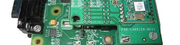
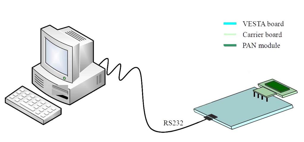
6 Figure 1 Figure 2-6
7 DEMONSTRATION KIT BLOCK DIAGRAM Figure 3-7

8 ESTABLISH COMMUNICATIONS To communicate to the each end of the PAN modules HyperTerminal is used to sends and received commands and data over the serial cable via the Vesta motherboard. The terminal window can be used to display the commands and data sent and received from the module. You can use any other terminal programs as long as they match and support the settings used with HyperTerminal. Setup HyperTerminal 1.) Open a HyperTerminal session. HyperTerminal can be found in Windows under Accessories and Communications. 2.) Type in a Terminal Name for this session, then press OK to continue. Figure 4-8
9 3.) Select the corresponding serial port the serial cable is connected on the PC to the Vesta board, then press OK to continue. Your COM choice maybe different from what is illustrated in Figure 5. Figure 5-9

10 4.) Set the Port Settings to the following parameters and then click Apply and OK a Bits per second; 8 Data bits; No Parity; 1 Stop Bit; No Flow Control Figure 6-10

11 5.) Set the terminal ACII data properties. Go to File and select properties and set the following then click OK. a. Check Echo typed Characters Locally b. Check Append line feeds to incoming line ends c. The rest leave to default. Figure 7-11

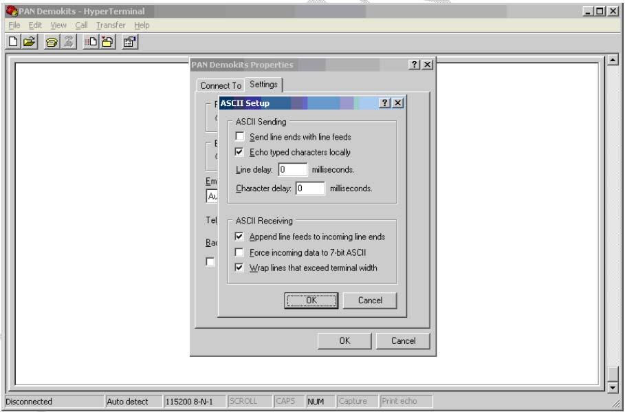
12 Figure 8 Figure 9-12
13 6.) Click the Call icon on the top of the menu bar to start the HyperTeminal session. Figure 10-13
14 SETUP RF CONNECTION A RF connection can be created between the two Vesta boards with the PAN modules attached. Two personal computers can be used or one personal computer with 2 separate serial ports can be used as well. One module will need to be setup as the transmitter while the other will need to be set as the receiver. Setup the Receiver The following setup of commands will need to be sent using HyperTerminal. After each command typed press Enter to send the command down. An acknowledgment will be sent back and displayed in the Hyperterminal window. Commands: a) ATR7 ; Reads the module name b) ATR8 ; Reads the Vesta board firmware version c) ATW12 ; Sets the PAN baseband frequency to MHz d) ATW22 ; Set the radio into receiver mode Figure 11-14
15 Setup the Transmitter Commands: a) ATR7 ; Reads the module name b) ATR8 ; Reads the Vesta board firmware version c) ATW12 ; Sets the PAN baseband frequency to MHz d) ATW ; Sets the transmit offset to Zero e) ATW5Hello World ; Sets HELLO WORLD to be transmitted over the air f) ATW23 ; Turns on the transmitter Figure 12-15
16 When you set the transmitter on with the ATW23 command, the data will immediately start to transmit. The HyperTerminal session connected to your receiving module will start to display the data. Figure 13-16
17 COMMAND PROTOCOL The Vesta board interprets commands by text strings sent from HyperTerminal and executes the command once it is received. If the command was received successfully, the Vesta board will send back an acknowledgement regarding the success, failure or data requested from the received command. The commands are read/write operations that are immediately executed once received by the Vesta board. There is a small set of commands to control PAN and the kit. The list of commands and acknowledgments can be found in the three tables below. Parameters and values Each write command and read acknowledgment must contain the write parameters or acknowledgment values. For write commands the parameter will need to be appended to the command. For read acknowledgments the returned acknowledgment will have the value appended to it. Examples: Command or Ack ATW1 ATR1 Parameter or Value ATW12 = Write baseband frequency to 868~870MHz ATw12 = Baseband frequency is 868~879MHz Commands Table 1: Commands Command Description Ack Details ATR1 Read Baseband ATw1 Reads the frequency operation of the baseband. Returns ATw1 with a value response. ATR2 Read RF State ATw2 Reads the RF state of the radio. Returns the RF state of the radio with a value response. ATR3 Read Transmit Power ATw3 Reads the Transmit Power of the radio in the TX state. Returns the power with a value response. ATR4 Reads Frequency Offset ATw4 Read the frequency offset of the radio. Returns with a value response. - 17
18 ATR5 Read RSSI Value ATw5 ATR6 Reads Frequency Error Indicator ATw6 ATR7 Read Radio Module ATw7 ATR8 Read Firmware Version ATw8 ATR9 ATW1 ATW2 ATW3 ATW4 ATW5 Read Transmit Buffer Select Baseband Frequency Write RF State Write Transmit Power Write Frequency Offset Write Transmit Content ATr11 ATr10 ATr21 ATr20 ATr30 ATr31 ATr40 ATr41 ATr50 ATr51 Reads the RSSI value of the radio in the RX state. Returns the RSSI in a value response. Reads the frequency error indicator. Returns the value of the error Reads the name of the radio module. Return a text string of the name of the module. Reads the firmware version of the Vesta motherboard. Reads the contents in the transmit buffer and the data to be transmitted over the radio. Selects the Baseband Frequency. Values: a) 0 = 216~218MHz b) 1 = 433~435MHz c) 2 = 767~870MHz d) 3 = 902~928MHz Writes and executes new RF state. Values: a) 0 = Sleep Mode b) 1 = Standby Mode c) 2 = Receive Mode d) 3 = Transmit Mode Writes and executes the new transmit power state in dbm Values: a) 0 = 0 dbm b) 1 = 5 dbm c) 2 = 10 dbm d) 3 = 15 dbm Writes and executes the new frequency offset. Value = ± XXXX KHz XXXX is 4 bytes long Writes the contents of data to be transmitted over the air. The content is a text string. i.e Hello World - 18
19 Acknowledgments Table 2: Acknowledgment Ack Description Description ATw1 Ack for ATW1 Returns the baseband frequency. Response values: a) 0 = Sleep Mode b) 1 = Standby Mode c) 2 = Receive Mode d) 3 = Transmit Mode ATw2 Ack for ATW2 Returns the RF State of the radio. Response values: a) 0 = Sleep Mode b) 1 = Standby Mode c) 2 = Receive Mode d) 3 = Transmit Mode ATw3 Ack for ATW3 Returns the transmit power of the radio. Response values: a) 0 = 0 dbm b) 1 = 5 dbm c) 2 = 10 dbm d) 3 = 15 dbm ATw4 Ack for ATW4 Returns the frequency offset of the radio. Response value: Value = ± XXXX KHz XXXX is 4 bytes long ATw5 Ack for ATW5 Returns the RSSI value. ATw6 Ack for ATW6 Returns the frequency error indicator ATw7 Ack for ATW7 Returns the name of the radio module. ATw8 Ack for ATW8 Returns the firmware version on the Vesta board. ATr11 ATr11 = Command Failed Ack for ATR1 ATr10 ATr10 = Command successful ATr21 ATr21 = Command Failed Ack for ATR2 ATr20 ATr20 = Command successful ATr30 ATr31 Ack for ATR3 ATr31 = Command Failed ATr30 = Command successful ATr40 ATr41 = Command Failed ATr41 ATr50 ATr51 Ack for ATR4 Ack for ATR5 ATr40 = Command successful ATr51 = Command Failed ATr50 = Command successful - 19
20 SUPPORT Please contact support on Unigen website if you have any problems setting up the demo. Forums For active discussions on PAN demo kits, you can visit to ask questions in regards to Unigen s products. - 20
RF Solution for LED Display Screen
 RF Solution for LED Display Screen Introduction RF is a kind of wireless telecommunication technology, now standard IEEE802.11B is much popular. Communication speed between server and terminal can reach
ATA8520D Production and EOL Testing. Features. Description ATAN0136 APPLICATION NOTE
 ATAN0136 ATA8520D Production and EOL Testing APPLICATION NOTE Features Test application for production and EOL testing of ATA8520-EK1-E/ EK2-E/ EK3-E evaluation kits PCB component tests, i.e., MCU, temperature
STEVAL-IKR001V7D. Sub Ghz transceiver daughterboard with power amplifier based on the SPIRIT1. Features. Description
 Sub Ghz transceiver daughterboard with power amplifier based on the SPIRIT1 Data brief Features SPIRIT1 low power sub GHz transceiver in a standalone RF module tuned for 169 MHz band with external power
RF4432 wireless transceiver module
 RF4432 wireless transceiver module 1. Description RF4432 adopts Silicon Lab Si4432 RF chip, which is a highly integrated wireless ISM band transceiver. The features of high sensitivity (-121 dbm), +20
Mini Gateway USB for ModFLEX Wireless Networks
 Mini Gateway USB for ModFLEX Wireless Networks FEATURES Compatible with all modules in the ModFLEX family. USB device interface & power Small package size: 2.3 x 4.9 External high performance antenna.
Control Commands VIDEO WALLS VIDEO PROCESSORS VIDEO MATRIX SWITCHES EXTENDERS SPLITTERS WIRELESS CABLES & ACCESSORIES. Control Your Video
 Control Your Video VIDEO WALLS VIDEO PROCESSORS VIDEO MATRIX SWITCHES EXTENDERS SPLITTERS WIRELESS CABLES & ACCESSORIES Control Commands Model #: SC-MLT-DVI-4 2015 Avenview Inc. All rights reserved. The
RF4432F27 wireless transceiver module
 RF4432F27 wireless transceiver module 1. Description RF4432F27 is 500mW RF module embedded with amplifier and LNA circuit. High quality of component, tightened inspection and long term test make this module
UG147: Flex Gecko 2.4 GHz, 20 dbm Range Test Demo User's Guide
 UG147: Flex Gecko 2.4 GHz, 20 dbm Range Test Demo User's Guide This user's guide provides an easy way to evaluate the link budget of the Wireless Gecko EFR32 devices using Silicon Labs Radio Abstraction
Anritsu Setup Procedure for GSP-1720 Measurements
 GS 09-1313 Rev. 1.0 11-April-2009 Purpose: This procedure demonstrates how to use the Anritsu MT8803G to place a GSP-1720 modem into a call state. After the lab technician becomes familiar with this process,
IMPORTANT NOTICE. Company name - STMicroelectronics NV is replaced with ST-NXP Wireless.
 IMPORTANT NOTICE Dear customer, As from August 2 nd 2008, the wireless operations of STMicroelectronics have moved to a new company, ST-NXP Wireless. As a result, the following changes are applicable to
SPSGRF-868 / 915 SubGiga (868 or 915 MHz) programmable transceiver module Datasheet
 programmable transceiver module Datasheet") -868 / 915 SubGiga (868 or 915 MHz) programmable transceiver module Datasheet Features Programmable Radio features - Modulation schemes: 2-FSK, GFSK, MSK, GMSK, OOk, ASK - Air data rate from 1 to 500 kbps
-868 / 915 SubGiga (868 or 915 MHz) programmable transceiver module Datasheet Features Programmable Radio features - Modulation schemes: 2-FSK, GFSK, MSK, GMSK, OOk, ASK - Air data rate from 1 to 500 kbps
Configuration Vestas VMP3500
 Configuration Vestas VMP3500 1. Table of contents 1. Table of contents... 2 2. Introduction... 3 3. Vestas turbines (RCS)... 4 3.1. VMP 3500 controller... 4 3.2. Communication with the CT3230 current loop
Datasheet. airmax ac CPE with Dedicated Management Radio. Model: LBE-5AC-Gen2. Lightweight, Low-Cost Solution. Full Adjustment Flexibility
 airmax ac CPE with Dedicated Management Radio Model: LBE-5AC-Gen2 Lightweight, Low-Cost Solution Full Adjustment Flexibility Quick Assembly and Installation Overview Ubiquiti Networks launches the latest
AT780PCI. Digital Video Interfacing Products. Multi-standard DVB-T2/T/C Receiver & Recorder & TS Player DVB-ASI & DVB-SPI outputs
 Digital Video Interfacing Products AT780PCI Multi-standard DVB-T2/T/C Receiver & Recorder & TS Player DVB-ASI & DVB-SPI outputs Standard Features - PCI 2.2, 32 bit, 33/66MHz 3.3V. - Bus Master DMA, Scatter
VT5365. Single-chip optical mouse sensor for wireless applications. Features. Applications. Technical specifications. Description.
 Single-chip optical mouse sensor for wireless applications Data Brief Features One chip solution with internal micro and minimal external circuitry 1.8V (single battery) or 2.0 V to 3.2 V (serial batteries)
M24SR-DISCOVERY. Discovery kit for the M24SR series Dynamic NFC/RFID tag. Features
 Discovery kit for the M24SR series Dynamic NFC/RFID tag Data brief Features Ready-to-use printed circuit board (PCB) including: M24SR64-Y Dynamic NFC/RFID tag 31 mm x 30 mm 13.56 MHz double layer inductive
AY-U910 UHF Integrated Long-Range Reader Installation and User Manual
 AY-U910 UHF Integrated Long-Range Reader Installation and User Manual Copyright 2016 by Rosslare. All rights reserved. This manual and the information contained herein are proprietary to ROSSLARE ENTERPRISES
N+1 Redundancy with the VCom HD4040 Upconverter
 N+1 Redundancy with the VCom HD4040 Upconverter Document ID: 47164 Contents Introduction Prerequisites Requirements Components Used Conventions Set Up Communication with the Upconverter VCom Dual4040D
ROBOT-M24LR16E-A. Evaluation board for the M24LR16E-R dual interface EEPROM. Features. Description
 Features Evaluation board for the M24LR16E-R dual interface EEPROM 20 mm x 40 mm 13.56 MHz inductive antenna etched on PCB M24LR16E-R dual interface EEPROM I²C connector Energy harvesting output (V OUT
EVM Data Guide. (Preliminary)
") EVM-915-250 Data Guide (Preliminary) Table of Contents 1 Description 2 Ordering Information 2 Electrical Specifications 4 Pin Assignments 5 Pin Descriptions 6 PCB Footprint 7 Schematic Diagram 8 Usage
EVM-915-250 Data Guide (Preliminary) Table of Contents 1 Description 2 Ordering Information 2 Electrical Specifications 4 Pin Assignments 5 Pin Descriptions 6 PCB Footprint 7 Schematic Diagram 8 Usage
Copyright 2013 ACURA Global. UHF860 RFID READER. User s manual. English draft TM970180
 Copyright 03 ACURA Global. UHF860 RFID READER User s manual English draft TM97080 April 0, 03 Copyright 03: without a written approval from ACURA Global Inc, this document is not allowed to be duplicated
Implementing Audio IP in SDI II on Arria V Development Board
 Implementing Audio IP in SDI II on Arria V Development Board AN-697 Subscribe This document describes a reference design that uses the Audio Embed, Audio Extract, Clocked Audio Input and Clocked Audio
GM60028H. DisplayPort transmitter. Features. Applications
 DisplayPort transmitter Data Brief Features DisplayPort 1.1a compliant transmitter HDCP 1.3 support DisplayPort link comprising four main lanes and one auxiliary channel Output bandwidth sufficient to
Obsolete Product(s) - Obsolete Product(s)
 - Obsolete Product(s)") Bluetooth low energy development kit based on the STBLC01 Features STBLC01 Bluetooth low energy controller in a standalone RF module STM32L Discovery board, including STLINK Associated STBLC01 development
Bluetooth low energy development kit based on the STBLC01 Features STBLC01 Bluetooth low energy controller in a standalone RF module STM32L Discovery board, including STLINK Associated STBLC01 development
PD18-73/PD18-73LF: GHz Two-Way 0 Power Splitter/Combiner
 DATA SHEET PD18-73/PD18-73LF: 1.71-1.99 GHz Two-Way 0 Power Splitter/Combiner Applications Signal distribution/combining GSM, WCDMA, PCS/DCS Features Low cost Low profile Small SOT-6 package (MSL1, 260
MENU EXECUTE Shiloh Road Alpharetta, Georgia (770) FAX (770) Toll Free
 FAX (770) Toll Free") Instruction Manual Model 2584-31 Combiner May 2011, Rev. A RF MONITOR GAIN = -15 MENU MODEL 2584 COMBINER CROSS TECHNOLOGIES INC. ALARM REMOTE POWER EXECUTE Data, drawings, and other material contained
Instruction Manual Model 2584-31 Combiner May 2011, Rev. A RF MONITOR GAIN = -15 MENU MODEL 2584 COMBINER CROSS TECHNOLOGIES INC. ALARM REMOTE POWER EXECUTE Data, drawings, and other material contained
Modbus for SKF IMx and Analyst
 User manual Modbus for SKF IMx and SKF @ptitude Analyst Part No. 32342700-EN Revision A WARNING! - Read this manual before using this product. Failure to follow the instructions and safety precautions
STEVAL-CCM003V1. Graphic panel with ZigBee features based on the STM32 and SPZBE260 module. Features. Description
 Graphic panel with ZigBee features based on the STM32 and SPZBE260 module Data brief Features Microsoft FAT16/FAT32 compatible library JPEG decoder algorithm S-Touch -based touch keys for menu navigation
Syntor X Flash Memory Module Revision C
 Syntor X Flash Memory Module Revision C The PIEXX SynXFlash memory module, along with the supplied PC software, replaces the original SyntorX code plugs and allows you to easily set modify and update your
User manual. Long Range Wireless HDMI/SDI HD Video Transmission Suite
 User manual Long Range Wireless HDMI/SDI HD Video Transmission Suite Preface Thanks for purchasing our Long Range Wireless HDMI/SDI HD Video Transmission Suite. Before using this product, read this user
Long Range Wireless HDMI/SDI HD Video Transmission Suite LINK-MI LM-SWHD01. User manual
 Long Range Wireless HDMI/SDI HD Video Transmission Suite LINK-MI LM-SWHD01 User manual Preface... 1 1. Cautions... 2 2. About... 3 3. Installation... 4 4. Operation instruction... 5 5. Maintenance... 6
Product model and standard
 Preface Thank you for purchasing the Ikan Blitz 400 HD Wireless Video System. This system features uncompressed high definition video with zero delay. Before using the product, please read this user s
WDP02 Wireless FHD Kit User Manual
 WDP02 Wireless FHD Kit User Manual Copyright Copyright 2015 by BenQ Corporation. All rights reserved. No part of this publication may be reproduced, transmitted, transcribed, stored in a retrieval system
Obsolete Product(s) - Obsolete Product(s)
 - Obsolete Product(s)") Features Camera with ZigBee connectivity based on the STM32 STM32-based camera with ZigBee connectivity Includes microsd card and ZigBee module Works with monitoring unit (order code STEVAL-CCM003V1) Camera
Features Camera with ZigBee connectivity based on the STM32 STM32-based camera with ZigBee connectivity Includes microsd card and ZigBee module Works with monitoring unit (order code STEVAL-CCM003V1) Camera
User Manual Published October 2015 Software Version 3.66 QRX200. The Ultimate in Receiver Flexibility
 User Manual Published October 2015 Software Version 3.66 QRX200 The Ultimate in Receiver Flexibility 1 KNOWING YOUR QRX200 RECEIVER... 4 FRONT... 4 REAR... 5 SIDE... 6 HOME SCREEN EXPLAINED... 7 MAIN MENU...
OEM Version. 1.0 INTRODUCTION Retail Version: Includes reader, USB cable and five peel & stick RFID tags
 DLP-RFID1 *LEAD-FREE* OEM Version FEATURES: ISO 15693 Tag-it HF-I Compatible Read UID of Up to 15 Tags Simultaneously 13.56MHz Reader/Writer Built-in Antenna: Up to 4-Inch Read Range FCC/IC/CE Modular
AT660PCI. Digital Video Interfacing Products. DVB-S2/S (QPSK) Satellite Receiver & Recorder & TS Player DVB-ASI & DVB-SPI outputs
 Satellite Receiver & Recorder & TS Player DVB-ASI & DVB-SPI outputs") Digital Video Interfacing Products AT660PCI DVB-S2/S (QPSK) Satellite Receiver & Recorder & TS Player DVB-ASI & DVB-SPI outputs Standard Features - PCI 2.2, 32 bit, 33/66MHz 3.3V. - Bus Master DMA, Scatter
Digital Video Interfacing Products AT660PCI DVB-S2/S (QPSK) Satellite Receiver & Recorder & TS Player DVB-ASI & DVB-SPI outputs Standard Features - PCI 2.2, 32 bit, 33/66MHz 3.3V. - Bus Master DMA, Scatter
STEVAL-ISB008V1. Standalone USB Li-Ion battery charger demonstration board based on the STw4102 and STM32F103C6. Features.
 Features Standalone USB Li-Ion battery charger demonstration board based on the STw4102 and STM32F103C6 Data brief The STw4102 Li-Ion battery charger IC: supports battery charging by USB or external DC
STEVAL-SPBT2ATV2. USB Dongle for the Bluetooth class 2 SPBT2532C2.AT module. Features. Description
 USB Dongle for the Bluetooth class 2 SPBT2532C2.AT module Data brief Features Bluetooth V2.1 board USB connection SMD antenna onboard RoHS compliant Description The demonstration board is a design tool
Dragon. manual version 1.6
 Dragon manual version 1.6 Contents DRAGON TOP PANEL... 2 DRAGON STARTUP... 2 DRAGON STARTUP SCREEN... 2 DRAGON INFO SCREEN... 3 DRAGON MAIN SCREEN... 3 TURNING ON A TRANSMITTER... 4 CHANGING MAIN SCREEN
Long Range Wireless HDMI/SDI HD Video Transmission Suite LINK-MI LM-SWHD01. User manual
 Long Range Wireless HDMI/SDI HD Video Transmission Suite LINK-MI LM-SWHD01 User manual Preface... 1 1. Cautions... 2 2. About... 3 3. Installation... 4 4. Operation instruction... 5 5. Maintenance... 6
User Instruction Manual IQDBT105. DVB-T/T2 Terrestrial Receiver & Monitor.
 User Instruction Manual IQDBT105 DVB-T/T2 Terrestrial Receiver & Monitor www.s-a-m.com Information and Notices Information and Notices Copyright and Disclaimer Copyright protection claimed includes all
Projection Display. Serial Interface Specification
 Projection Display Serial Interface Specification Version: 2.0 Projection Display Serial Interface Spec. 1/1 Table of Contents 1. RS232 SETTING...3 2. CONTROL COMMAND STRUCTURE...3 3. CONTROL SEQUENCE...3
AW900mT. User s Manual. Point-to-multipoint. Industrial-grade, ultra-long-range 900 MHz non-line-of-sight wireless Ethernet systems
 User s Manual Point-to-multipoint Industrial-grade, ultra-long-range 900 MHz non-line-of-sight wireless Ethernet systems User s Manual Non-line-of-sight :: 900 MHz Thank you for your purchase of the multipoint
DEMO MANUAL DC2668A LTC5552 3GHz to 20GHz Microwave Mixer with Wideband DC to 6GHz IF BOARD PHOTO
 DESCRIPTION LTC5552 3GHz to 20GHz Microwave Mixer with Wideband DC to 6GHz IF ABSOLUTE MAXIMUM INPUTS Demonstration circuit 2668A is optimized for evaluation of the LTC 5552 passive double-balanced mixer.
Check our knowledge base at
 USER MANUAL Check our knowledge base at www.paralinx.net/support Copyright 2015 Paralinx LLC All Rights Reserved TABLE OF CONTENTS 1 Important Notice 10 LCD Screen 2 Safety Instructions 11 Indicators 3
SatLabs Recommendation for a Common Inter-Facility Link for DVB-RCS terminals
 SatLabs Recommendation for a Common Inter-Facility Link for DVB-RCS terminals Version 1.6-06/01/2005 This document is the result of a cooperative effort undertaken by the SatLabs Group. Neither the SatLabs
STEVAL-ICB004V1. Advanced resistive touchscreen controller demonstration board based on the STMPE811. Features. Description
 Advanced resistive touchscreen controller demonstration board based on the STMPE811 Data brief Features Four-wire resistive touch-sensing demonstration GUI Configurable touch-sensing parameters STMPE811
ТМ-04 Multichannel long range UHF alarm transmitter Operating manual. Sectron Ltd.
 Office: 52 G.M.Dimitrov blvd. 1125 Sofia tel: 02 91982 fax: 02 732576 TM-04 revision V1.0. ТМ-04 Multichannel long range UHF alarm transmitter Operating manual Sectron Ltd. www.sectron.com TM-04 description
AT2700USB. Digital Video Interfacing Products. DVB-C QAM-A/B/C IF and RF ( VHF & UHF ) Output DVB-ASI & DVB-SPI Inputs
 Output DVB-ASI & DVB-SPI Inputs") Digital Video Interfacing Products AT2700USB DVB-C QAM-A/B/C IF and RF ( VHF & UHF ) Output DVB-ASI & DVB-SPI Inputs Standard Features DVB-C Modulator with VHF & UHF up converter. - High Speed USB 2.0.
Digital Video Interfacing Products AT2700USB DVB-C QAM-A/B/C IF and RF ( VHF & UHF ) Output DVB-ASI & DVB-SPI Inputs Standard Features DVB-C Modulator with VHF & UHF up converter. - High Speed USB 2.0.
Intel Ethernet SFP+ Optics
 Product Brief Intel Ethernet SFP+ Optics Network Connectivity Intel Ethernet SFP+ Optics SR and LR Optics for the Intel Ethernet Server Adapter X520 Family Hot-pluggable SFP+ footprint Supports rate selectable
Cat5 DVI-D Extender. User s Guide Avenview Inc. All rights reserved.
 Cat5 DVI-D Extender User s Guide 2007 Avenview Inc. All rights reserved. The contents of this document are provided in connection with Avenview Inc. ( Avenview ) products. Avenview makes no representations
GM68020H. DisplayPort receiver. Features. Applications
 DisplayPort receiver Data Brief Features DisplayPort 1.1a compliant receiver HDCP 1.3 support DisplayPort link comprising four main lanes and one auxiliary channel Input bandwidth sufficient to receive
AT270USB, imod. Digital Video Interfacing Products. Stand alone DVB-C Modulator IF and RF ( VHF & UHF ) Output DVB-ASI Input
 Output DVB-ASI Input") Digital Video Interfacing Products AT270USB, imod Stand alone DVB-C Modulator IF and RF ( VHF & UHF ) Output DVB-ASI Input Standard Features DVB-C Modulator with VHF & UHF Up converter. - High Speed USB
Digital Video Interfacing Products AT270USB, imod Stand alone DVB-C Modulator IF and RF ( VHF & UHF ) Output DVB-ASI Input Standard Features DVB-C Modulator with VHF & UHF Up converter. - High Speed USB
AT278USB, imod. Digital Video Interfacing Products. DVB-T/H/C & ATSC Modulator IF and RF ( VHF & UHF ) Output DVB-ASI Input
 Output DVB-ASI Input") Digital Video Interfacing Products AT278USB, imod DVB-T/H/C & ATSC Modulator IF and RF ( VHF & UHF ) Output DVB-ASI Input Standard Features DVB-T/H/C Modulator with VHF & UHF Up converter. - High Speed
Digital Video Interfacing Products AT278USB, imod DVB-T/H/C & ATSC Modulator IF and RF ( VHF & UHF ) Output DVB-ASI Input Standard Features DVB-T/H/C Modulator with VHF & UHF Up converter. - High Speed
Instruction Manual Model
 Instruction Manual Model 4115-267 Ka-Band Block Upconverter May 2015, Rev. C Data, drawings, and other material contained herein are proprietary to Cross Technologies, Inc., but may be reproduced or duplicated
USB-TG124A Tracking Generator User Manual
 USB-TG124A Tracking Generator User Manual Signal Hound USB-TG124A User Manual 2017, Signal Hound, Inc. 35707 NE 86th Ave La Center, WA 98629 USA Phone 360.263.5006 Fax 360.263.5007 This information is
APM CALIBRATION PROCEDURE Rev. A June 3, 2015
 APM CALIBRATION PROCEDURE Rev. A June 3, 2015 Calibration of the APM allows system parameters such as coupler coupling values, interconnecting cable losses and system feeder losses to be programmed into
GM69010H DisplayPort, HDMI, and component input receiver Features Applications
 DisplayPort, HDMI, and component input receiver Data Brief Features DisplayPort 1.1 compliant receiver DisplayPort link comprising four main lanes and one auxiliary channel HDMI 1.3 compliant receiver
Booya16 SDR Datasheet
 Booya16 SDR Radio Receiver Description The Booya16 SDR radio receiver samples RF signals at 16MHz with 14 bits and streams the sampled signal into PC memory continuously in real time. The Booya software
Altum Series DATASHEET
 DS-1034-J 1 of 5 Altum Series Overview Altum AC is a multi-functional, 2x2 MIMO, long-range, outdoor WiFi router, access point, and client station for wireless Ethernet bridge applications as well as outdoor
USB Mini Spectrum Analyzer User s Guide TSA5G35
 USB Mini Spectrum Analyzer User s Guide TSA5G35 Triarchy Technologies, Corp. Page 1 of 21 USB Mini Spectrum Analyzer User s Guide Copyright Notice Copyright 2011 Triarchy Technologies, Corp. All rights
User Manual Wireless HD AV Transmitter & Receiver Kit
 Ma User Manual Wireless HD AV Transmitter & Receiver REV.1.0 Thank you for purchasing this Wireless HD AV Transmitter & Receiver. Please read the following instructions carefully for your safety and prevention
HawkEye 1500 Series Quick Start Guide V2.4.1, Nov 2008
 HawkEye 1500 Series Quick Start Guide V2.4.1, Nov 2008 EM-40390-1V241 Copyright and Disclaimer Copyright 2008 by Microscan Systems, Inc. 1201 S.W. 7th Street, Renton, WA, U.S.A. 98057 (425) 226-5700 FAX:
Instruction Manual Model Block Up/Downconverter
 Instruction Manual Model 4117-14 Block Up/Downconverter Weather Resistant Unit March 2017, Rev. J Data, drawings, and other material contained herein are proprietary to Cross Technologies, Inc., but may
Yellow Frog. Manual Version 1.1
 Yellow Frog Manual Version 1.1 1 YellowFrog Contents PC Requirements...... 2 YellowFrog Power Meter Measurement.... 3 YellowFrog PC Software..... 3 Main Screen....... 4 Input Overload....... 5 Battery
Concise NFC Demo Guide using R&S Test Equipment Application Note
 Concise NFC Demo Guide using R&S Test Equipment Application Note Products: R&S SMBV100A R&S SMBV-K89 R&S FS-K112PC R&S RTO R&S RTO-K11 R&S CSNFC-B8 R&S FSL R&S FSV R&S FSW R&S ZVL This concise NFC Demo
VJ 6040 UHF Chip Antenna for Mobile Devices
 End of Life Last Available Purchase Date: 2-Aug-217 VJ 64 UHF Chip Antenna for Mobile Devices VJ 64 The company s products are covered by one or more of the following: WO5262 (A1), US2833 (A1), US283575
Extra long-range RFID (proximity) card reader
 card reader") GP90A Extra long-range RFID (proximity) card reader (1) Features: Extra long reading range of up to 90 cm with ISO-size passive RFID cards*, over 100 cm with special optimized passive cards High-precision
GP90A Extra long-range RFID (proximity) card reader (1) Features: Extra long reading range of up to 90 cm with ISO-size passive RFID cards*, over 100 cm with special optimized passive cards High-precision
AT720USB. Digital Video Interfacing Products. DVB-C (QAM-B, 8VSB) Input Receiver & Recorder & TS Player DVB-ASI & DVB-SPI outputs
 Input Receiver & Recorder & TS Player DVB-ASI & DVB-SPI outputs") Digital Video Interfacing Products AT720USB DVB-C (QAM-B, 8VSB) Input Receiver & Recorder & TS Player DVB-ASI & DVB-SPI outputs Standard Features - High Speed USB 2.0. - Windows XP, Vista, Win 7 ( 64bit
Digital Video Interfacing Products AT720USB DVB-C (QAM-B, 8VSB) Input Receiver & Recorder & TS Player DVB-ASI & DVB-SPI outputs Standard Features - High Speed USB 2.0. - Windows XP, Vista, Win 7 ( 64bit
Netzer AqBiSS Electric Encoders
 Netzer AqBiSS Electric Encoders AqBiSS universal fully digital interface Application Note (AN-101-00) Copyright 2003 Netzer Precision Motion Sensors Ltd. Teradion Industrial Park, POB 1359 D.N. Misgav,
ST30HPT User Manual. Contents SUNTOR ELECTRONICS CO., LIMITED
 ST30HPT User Manual TX on Board RX on Ground Contents I. Disclaimer...2nd II. Precautions for integration...2nd III. List of in-box items...3rd IV. Interface Definition... 5th 1. TX Interface Definition...5th
iosd (On Screen Display)
") iosd (On Screen Display) User Manual V1.4 2012-12-04 www.dji-innovations.com 2012 DJI Innovations. All Rights Reserved. 1 Disclaimer Thank you for purchasing product(s) from DJI Innovations. Please read
iosd (On Screen Display) User Manual V1.4 2012-12-04 www.dji-innovations.com 2012 DJI Innovations. All Rights Reserved. 1 Disclaimer Thank you for purchasing product(s) from DJI Innovations. Please read
QPC6222SR GENERAL PURPOSE DPDT TRANSFER SWITCH. Product Overview. Key Features. Functional Block Diagram. Applications. Ordering Information
 Product Overview The is a dual-pole double-throw transfer switch designed for general purpose switching applications where RF port transfer (port swapping) control is needed. The low insertion loss along
4X1 Gefen TV Switcher. GTV-HDMI N. User Manual
 4X1 Gefen TV Switcher GTV-HDMI1.3-441N User Manual www.gefentv.com ASKING FOR ASSISTANCE Technical Support: Telephone (818) 772-9100 (800) 545-6900 Fax (818) 772-9120 Technical Support Hours: 8:00 AM to
Setting up the communication between a Total Station and SiteMaster range of products
 Setting up the communication between a Total Station and SiteMaster range of products Before we set up the communication, one important thing to know.. Please NOTE that to check any setup and take measurements
DSM GHz Linear Chirping Source
 DSM202 2.0 GHz GENERAL DESCRIPTION The DSM202 is a linear chirping waveform module that generates two types of chirping waveforms at 32 clocks per frequency update. The DSM202 can be controlled using a
Noise Detector ND-1 Operating Manual
 Noise Detector ND-1 Operating Manual SPECTRADYNAMICS, INC 1849 Cherry St. Unit 2 Louisville, CO 80027 Phone: (303) 665-1852 Fax: (303) 604-6088 Table of Contents ND-1 Description...... 3 Safety and Preparation
5V +10V. Figure 1. DC2622A Connection Diagram
 Description Demonstration circuit 2622A features the amplifier. The DC2622A includes two of these amplifiers and is designed to drive the inputs of the DC2290 demo board. The DC2290 features the LTC 2387
AT2780USB. Digital Video Interfacing Products. DVB-T/H/C & ATSC Modulator IF and RF ( VHF & UHF ) Output DVB-ASI & DVB-SPI Inputs
 Output DVB-ASI & DVB-SPI Inputs") Digital Video Interfacing Products AT2780USB DVB-T/H/C & ATSC Modulator IF and RF ( VHF & UHF ) Output DVB-ASI & DVB-SPI Inputs Standard Features DVB-T/H/C Modulator with VHF & UHF Up converter. - High
Digital Video Interfacing Products AT2780USB DVB-T/H/C & ATSC Modulator IF and RF ( VHF & UHF ) Output DVB-ASI & DVB-SPI Inputs Standard Features DVB-T/H/C Modulator with VHF & UHF Up converter. - High
MyM-3S Micro Master. Installation Guide. English. design for TV
 MyM-3S Micro Master Installation Guide design for TV 1 CONTENT 1. Introduction 2. Unpacking the unit 3. Connections and indications 4. IP settings 5. Menus and settings 5.1 Overview menu 5.2 Input settings
HV-122-DCA DVB-T 2-Way Diversity Receiver Box Quick Installation Guide
 HV-122-DCA DVB-T 2-Way Diversity Receiver Box Quick Installation Guide PACKAGE CONTENTS 4 FRONT PANEL VIEW 4 BACK PANEL VIEW 4 BOARD VIEW 5 IR REMOTE CONTROLLER-TYPE A 6 FILL BATTERY TO IR CONTROLLERS:
4X1 Gefen TV Switcher GTV-HDMI N. User Manual
 4X1 Gefen TV Switcher GTV-HDMI1.3-441N User Manual INTRODUCTION Congratulations on your purchase of the 4x1 GefenTV Switcher. Your complete satisfaction is very important to us. GefenTV GefenTV is a unique
SERDES Eye/Backplane Demo for the LatticeECP3 Serial Protocol Board User s Guide
 for the LatticeECP3 Serial Protocol Board User s Guide March 2011 UG24_01.4 Introduction This document provides technical information and instructions on using the LatticeECP3 SERDES Eye/Backplane Demo
10MHz Source/Inserter
 Instruction Manual Model 2099-218 10MHz Source/Inserter Redundant 18V January 2011, Rev. A RX 0.32 A TX 0.86 A REF ON REF OFF MENU MODEL 2099 SOURCE/INSERTER CROSS TECHNOLOGIES INC. PS1 PS2 REMOTE ALARM
AT70XUSB. Digital Video Interfacing Products
 Digital Video Interfacing Products AT70XUSB DVB-C (QAM-A) Cable TV Input DVB-C to DVB-ASI Converter Receiver, Recorder & Converter Small Handheld size No External Power Supply needed Standard Features
Operating Manual. 50mW C-Band EDFA with GPIB and RS232 Interface
 Fibotec Fiberoptics GmbH Herpfer Str. 40 98617 Meiningen Germany Tel. +49 3693 8813-200 Fax. +49 3693 8813-201 www.fibotec.com Operating Manual 50mW C-Band EDFA with GPIB and RS232 Interface (Version 1.1
2W Wireless Mobile Video Transmitter (ST6000TKMD) User Manual
 User Manual") 2W Wireless Mobile Video Transmitter (ST6000TKMD) User Manual TENG YUANZHI SHENZHEN ELECTRONICS CO.,LTD. 2010.10.23 1 Features Low system latency COFDM modulation, Stable transmission MPEG-2 video compression,
2W Wireless Mobile Video Transmitter (ST6000TKMD) User Manual TENG YUANZHI SHENZHEN ELECTRONICS CO.,LTD. 2010.10.23 1 Features Low system latency COFDM modulation, Stable transmission MPEG-2 video compression,
TransitHound Cellphone Detector User Manual Version 1.3
 TransitHound Cellphone Detector User Manual Version 1.3 RF3 RF2 Table of Contents Introduction...3 PC Requirements...3 Unit Description...3 Electrical Interfaces...4 Interface Cable...5 USB to Serial Interface
Instruction Manual Model
 Instruction Manual Model 4116-275 Ka-Band Block Downconverter Weather Resistant Unit April 2015, Rev. B Data, drawings, and other material contained herein are proprietary to Cross Technologies, Inc.,
IEEE802.11a Based Wireless AV Module(WAVM) with Digital AV Interface. Outline
 with Digital AV Interface. Outline") IEEE802.11a Based Wireless AV Module() with Digital AV Interface TOSHIBA Corp. T.Wakutsu, N.Shibuya, E.Kamagata, T.Matsumoto, Y.Nagahori, T.Sakamoto, Y.Unekawa, K.Tagami, M.Serizawa Outline Background
IEEE802.11a Based Wireless AV Module() with Digital AV Interface TOSHIBA Corp. T.Wakutsu, N.Shibuya, E.Kamagata, T.Matsumoto, Y.Nagahori, T.Sakamoto, Y.Unekawa, K.Tagami, M.Serizawa Outline Background
User Manual Published September 2015 Software Version RX2-405 RX200. Goes Anywhere
 User Manual Published September 2015 Software Version RX2-405 RX200 Goes Anywhere 1 RX200... 4 FRONT... 4 REAR... 5 SIDE... 6 HOME SCREEN... 7 MAIN MENU... 8 NAVIGATING THE MAIN MENU... 8 EXITING THE MAIN
Datasheet. 5 GHz airmax AC AP. Models: LAP-120, LAP-GPS. High-Performance Sector AP. Up To 450+ Mbps Real TCP/IP Throughput
 5 GHz airmax AC AP Models: LAP-120, High-Performance Sector AP Up To 450+ Mbps Real TCP/IP Throughput Lightweight, Low-Cost Solution Application Examples Introducing the airmax LiteAP AC, the latest high-performance
VDT-100 User Manual 1
 VDT-100 User Manual 1 Copyright Notice The use manual, including all its contents, is copyrighted by Videa Technology Inc.. All rights are reserved. Videa Technology Inc. reserves the right to improve
Radiocrafts Embedded Wireless Solutions
 Wireless M-Bus High power N Mode RF Transceiver Module EN 13757-4:2013) Product Description The RC1701HP-MBUS is part of a compact surface-mounted Wireless M-Bus module family that measures only 12.7 x
Data Sheet. ISP WHDI Transmit Module. Features. Description
 ISP090903 WHDI Transmit Module Features Video transmission from STB, game console, Blu-ray or AV-R player, to Large Screen TV or Projector WHDI Transmitter: uncompressed Full-HD video quality. WHDI 1.0
R4 AIS Class B Transponder
 Saab TransponderTech R4 AIS Class B Transponder Configuration Manual GENERAL Page 1 i Copyright The entire contents of this manual and its appendices, including any future updates and modifications, shall
Quick Start Guide Camera Slot Dual UHF Receiver
 Quick Start Guide Camera Slot Dual UHF Receiver SRC-941 Digital Hybrid Wireless Technology U.S. Patent 7,225,135 Fill in for your records: Serial Number: Purchase Date: This guide is intended to assist
SKY : MHz High Linearity, Single Up/Downconversion Mixer
 DATA SHEET SKY73063-11: 1700 2100 MHz High Linearity, Single Up/Downconversion Mixer Applications 2G/3G base station transceivers: GSM/EDGE, CDMA, UMTS/WCDMA Wi-Fi (802.11) WiMAX (802.16) 3GPP Long-Term
DVB-T Box, USB Monheim/Germany Tel. +49 (0)9091/ Fax +49 (0)9091/ Hama GmbH & Co KG.
9091/ Fax +49 (0)9091/ Hama GmbH & Co KG.") www.hama.de Hama GmbH & Co KG Postfach 80 86651 Monheim/Germany Tel. +49 (0)9091/502-0 Fax +49 (0)9091/502-274 hama@hama.de www.hama.de 00062776-01.05 DVB-T Box, USB 2.0 00062776 L TV USB receiver User
www.hama.de Hama GmbH & Co KG Postfach 80 86651 Monheim/Germany Tel. +49 (0)9091/502-0 Fax +49 (0)9091/502-274 hama@hama.de www.hama.de 00062776-01.05 DVB-T Box, USB 2.0 00062776 L TV USB receiver User