Senior Project Manager / AEO
|
|
|
- Roland King
- 5 years ago
- Views:
Transcription

1 Kenny Liao &20 Senior Project Manager / AEO


2 Measurement Demo Prepare instrument for measurement Calibration Fixture removal Conclusion What next? Future trends Resources Acquire channel data Multi-port S-parameter measurement Live Demo Design case study Complete channel analysis TDR, PAM4 eye diagram, etc Analyze channel performance Single-ended vs. differential Eye diagrams (NRZ, PAM4), COM Q&A 2
3 Measurement Demo Prepare instrument for measurement Calibration Fixture removal Conclusion What next? Future trends Resources Acquire channel data Multi-port S-parameter measurement Live Demo Design case study Complete channel analysis TDR, PAM4 eye diagram, etc Analyze channel performance Single-ended vs. differential Eye diagrams (NRZ, PAM4), COM Q&A 3
4 Why do we have to calibrate? It is impossible to make perfect hardware (couplers, switches, etc.) Even with highest quality components, some error exists How do we get accuracy? With vector-error-corrected calibration Not the same as the yearly instrument calibration What does calibration do for us? Removes the largest contributor to measurement uncertainty: systematic errors Provides best picture of true performance of DUT Systematic error 4
5 Device Length Frequency Range Accuracy Repeatability Reciprocity Normalization SOLT Device Complexity Voltage & Temp Drift Calibration Risetime Number of Points Time Step Averaging Time Base IF BW Instrument Architectures Source Error Source Drift Rcvr BW Source Stability Noise Floor Dynamic Range Signal-to-Noise Ratio Filter Roll-off 5
6 Errors: Measured Data SYSTEMATIC RANDOM Unknown Device DRIFT Systematic errors Due to imperfections in the analyzer and test setup Assumed to be time invariant (predictable) Generally, are largest sources or error Random errors Vary with time in random fashion (unpredictable) Main contributors: instrument noise, switch and connector repeatability Drift errors Due to system performance changing after a calibration has been done Primarily caused by temperature variation and cabling 6
7 R Directivity A Crosstalk B DUT Frequency response Reflection tracking (A/R) Transmission tracking (B/R) Source Mismatch Load Mismatch Six forward and six reverse error terms yields 12 error terms for two-port devices 7
8 8

9 9


10 Short Open Load Through Electronic Calibration Module Advantages Easy, prevents cable/connector wear and SAVES TIME Disadvantages N/A Mechanical Calibration Kit More accurate Slow and tedious especially for multiport applications 10
11 We know about Short-Open-Load-Thru (SOLT) calibration... What is TRL? Good for non-coaxial environments (PCBs, fixtures, wafer probing) Characterizes same 12 systematic errors as the more common SOLT cal Other variations: Line-Reflect-Match (LRM), Thru-Reflect-Match (TRM), plus many others User must fabricate the calibration standards TRL was developed for non-coaxial microwave measurements 11


12 A good TRL cal kit is difficult to design and fabricate due to launch repeatability, PCB impedance variations, and typical PCB manufacturing tolerances 12

13 What else can be done? Make sure that the Ecal has an up-to-date factory calibration Clean all the coaxial connectors as described in the Connector Care App Note How important are the test cables? Extremely. Would you put bias ply tires on a Ferrari? Don t try to save money on test cables Any movement of test cable between calibration and measurement shift phase of measurement. Don t exceed the recommended bend radius. Tape down the test cables. Learn from the lab metrologists. 13
14 Measurement Demo Prepare instrument for measurement Calibration Fixture removal Conclusion What next? Future trends Resources Acquire channel data Multi-port S-parameter measurement Live Demo Design case study Complete channel analysis TDR, PAM4 eye diagram, etc Analyze channel performance Single-ended vs. differential Eye diagrams (NRZ, PAM4), COM Q&A 14
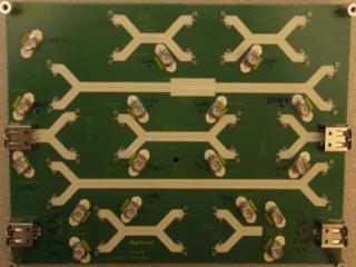
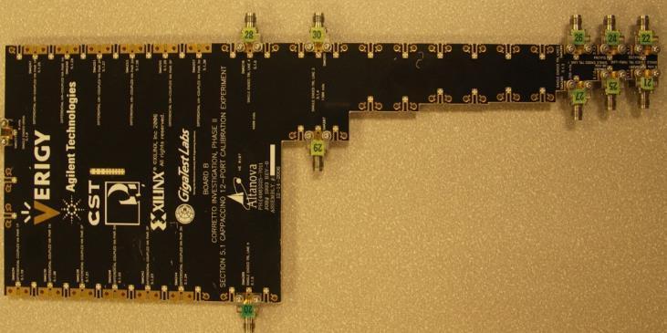
15 Determine VNA testing requirements Frequency Range? Number of Ports? Active or Passive device test? Probing system or fixturing? Accessories and specialist software tools? (aka here are some powerful PLTS features that allow you to play with data ) 15


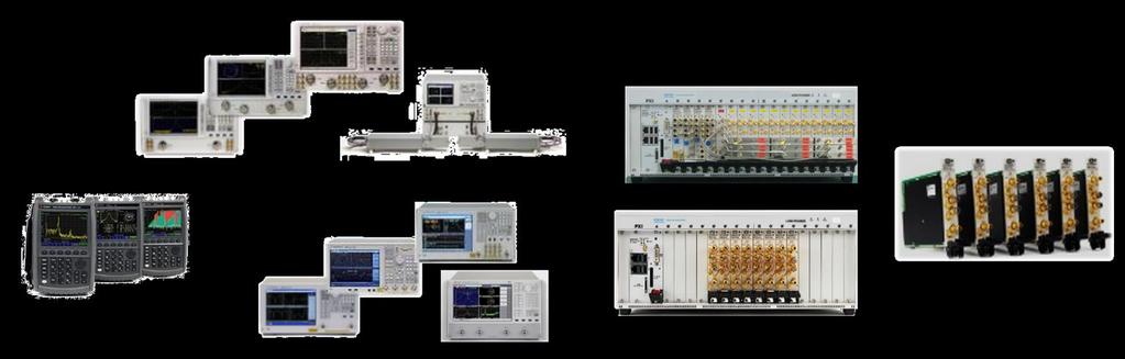
16 4-port 120GHz PNA+PLTS System 32-port 26.5GHz PXI-based PNA+PLTS System 16

17 17
18 Integration High Low Duplexers Diplexers Filters Couplers Bridges Splitters, dividers Combiners Isolators Circulators Attenuators Adapters Opens, shorts, loads Delay lines Cables Transmission lines Resonators Dielectrics R, L, C's Antennas Switches Multiplexers Mixers Samplers Multipliers Diodes RFICs MMICs T/R modules Transceivers Receivers Tuners Converters VCAs Amplifiers VTFs Modulators VCAtten s Transistors Passive Device type Active 18


19 Integration High Low Duplexers Diplexers Filters Couplers Bridges Splitters, dividers Combiners Isolators Circulators Attenuators Adapters Opens, shorts, loads Delay lines Cables Transmission lines Resonators Dielectrics R, L, C's Backplanes PCBs Cables Connectors Packages Antennas Switches Multiplexers Mixers Samplers Multipliers Diodes RFICs MMICs T/R modules Transceivers Receivers Tuners Converters VCAs Amplifiers VTFs Modulators VCAtten s Transistors Passive Device type Active 19
20 Probing Advantage Flexibility Disadvantage Expensive Need ISS calibration substrate for probe tip ref plane 20


21 Probing Advantage Flexibility Disadvantage Expensive Need ISS calibration substrate for probe tip ref plane Fixtures Advantage Easy to Use Disadvantage Each application requires different fixture Not electrically transparent, they have mismatch, loss and delay that must be characterized and removed from the DUT measurement (de-embed) 21
22 Measurement Demo Prepare instrument for measurement Calibration Fixture removal Conclusion What next? Future trends Resources Acquire channel data Multi-port S-parameter measurement Live Demo Design case study Complete channel analysis TDR, PAM4 eye diagram, etc Analyze channel performance Single-ended vs. differential Eye diagrams (NRZ, PAM4), COM Q&A 22
 Effective Return Loss")
23 Traditional analysis: IL, RL, Zo, NEXT,FEXT, Eye diagrams, etc Emerging standards proposing new test methods Complexity increases, software tools can minimize the learning curve New Figures of Merit are creating measurement challenges PAM4 eye diagram Channel Operating Margin (COM) Effective Return Loss (ERL) 23


24 For a SerDes engineer COM is: A reference chip capability SNR budget of a receiver For a channel engineer COM is: A budget between insertion loss, return loss, reflections, and crosstalk A management tool for trade offs between via stub, material selection, PCB constructions, connector choice. Courtesy of Richard Mellitz of Samtec 24
25 25

26 Measure passive channel Import data into PLTS Call MATLAB script Publish automatic results 26


27 The Challenge: Typical Issues: Solution: Scenario: >12-port VNA Data Lost track of port numbering Crosstalk data is unclear Let the tool do the memory work Use N1930B PLTS 2018 software Calibration Measurement Analysis Import data into PLTS Call MATLAB script Publish automatic results 27
 are technologies that will enable 400G")
28 Demand for increased network bandwidth in data centers 400G links will be the next step in meeting the need for speed Multi-level signaling formats such as Pulse Amplitude Modulation (PAM-N) are technologies that will enable 400G implementation 28


29 PAM4 is a next generation multilevel signaling architecture NRZ PAM4 29


30 Traditional Method PRBS pattern generator Drive DUT Measure w/scope Newer Method Measure s-parameters of DUT w/vna Synthesize PAM4 mathematically 86100D Digital Communications Analyzer N1930B Physical Layer Test System 30


31 Introduction to Hyperscale Data Centers Trends Technical Issues Design Case Study #1 56G PAM4 Channel Deembedding Methods Types of Error Correction Automatic Fixture Removal Before and After Comparison Design Case Study #2 PCI-E Memory Bus Test Fixture PAM4 Analysis Why needed? Compare to NRZ Conclusion 31


32 IC Evaluation Board IC : etopus 56G PAM-4 Connection to The Scope : MXP Connector + 50cm 2.4mm High Bandwidth cable * Device Under Test courtesy of Etopus Company 32
33 Test Point with De-Embedding Test Point without De-Embedding 50cm 2.4mm cable To Oscilloscope PAM-4 Transceiver PCB Trace MXP Connector 50cm 2.4mm cable 2X Thru calibration Trace for AFR Example: PAM4 PHY supporting 50/100/200/400 GbE Copper Interconnects for Hyperscale & Enterprise Data Centers 33
 34")
34 2X Thru Replica Trace Extract S-parameter with 2.4mmm high bandwidth cable connected to MXP connector. Test Equipment :Keysight N5225A Network Analyzer Keysight PLTS (N1930B Physical Layer Test System) 34

35 De-Embed Model Extracted By AFR / Insertion Loss 1X AFR model extracted using AFR 35


36 PAM-4 Waveform Before/After De-Embedding BEFORE AFTER Excellent Waveform! This is true IC performance. 36
37 De-Embedding is very effective to analyze true signal characteristics in composite measurement especially for ultra high speed and complex signaling such as 56G PAM-4. Even if high quality connector and cable are used, the effect from those components are not negligible in 56G PAM-4. Channel analysis and modeling for the system is very important. 37
38 Measurement Demo Prepare instrument for measurement Calibration Fixture removal Conclusion What next? Future trends Resources Acquire channel data Multi-port S-parameter measurement Live Demo Design case study Complete channel analysis TDR, PAM4 eye diagram, etc Analyze channel performance Single-ended vs. differential Eye diagrams (NRZ, PAM4), COM Q&A 38

39 Now we have accurate s-parameters, so what now? Prepare data for analysis Dissect the channel data Explore the design space Extract Dk, Loss/in/GHz Analyze TDR impedance profile Single Pulse Response Correlate measurements/models 39
40 Accurate VNA measurements require an understanding of calibration and error correction Various hardware and software configurations can optimize your time in the measurement lab De-embedding is necessary to obtain true DUT measurement Viewing the measured data in different domains reveals a lot more information Overall, given proper measurement, analysis and simulation tools, you will be able to extract the material properties, create a channel model and optimize your channel for high speed 40


41 Physical Layer Test System Home: Digital Interconnect Test System: Free Signal Integrity Book: S-parameters: Signal Integrity Analysis in the Blink of an Eye
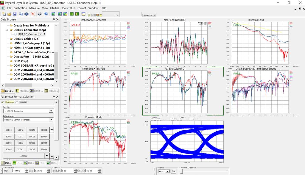
42 Theory Practical Overview Brief history Internet infrastructure Typical PCB Issues Vias, reflections, loss De-embedding Transmission Lines Differential impedance Multi-port S-parameters Real World Measurements Backplane Design Case Study Measurement Metrics Single-ended vs. differential Eye diagrams (NRZ, PAM4), Demonstration Physical Layer Test System (PLTS) USB 3.0 compliance example 42

43 XAUI extended Attachment Unit Interface 43
44 44
45 45
46 46
Practical De-embedding for Gigabit fixture. Ben Chia Senior Signal Integrity Consultant 5/17/2011
 Practical De-embedding for Gigabit fixture Ben Chia Senior Signal Integrity Consultant 5/17/2011 Topics Why De-Embedding/Embedding? De-embedding in Time Domain De-embedding in Frequency Domain De-embedding
A Simple, Yet Powerful Method to Characterize Differential Interconnects
 A Simple, Yet Powerful Method to Characterize Differential Interconnects Overview Measurements in perspective The automatic fixture removal (AFR) technique for symmetric fixtures Automatic Fixture Removal
SI Analysis & Measurement as easy as mobile apps ISD, ADK, X2D2
 SI Analysis & Measurement as easy as mobile apps ISD, ADK, X2D2 Ching-Chao Huang huang@ataitec.com Outline Can SI tools be made like mobile apps? Introduction of AtaiTec SI software Most applications in
Microwave Interconnect Testing For 12G-SDI Applications
 DesignCon 2016 Microwave Interconnect Testing For 12G-SDI Applications Jim Nadolny, Samtec jim.nadolny@samtec.com Corey Kimble, Craig Rapp Samtec OJ Danzy, Mike Resso Keysight Boris Nevelev Imagine Communications
Tutorial Session 8:00 am Feb. 2, Robert Schaefer, Agilent Technologies Feb. 2, 2009
 Tutorial Session 8:00 am Feb. 2, 2009 Robert Schaefer, Agilent Technologies Feb. 2, 2009 Objectives Present Advanced Calibration Techniques Summarize Existing Techniques Present New Advanced Calibration
SCSI Cable Characterization Methodology and Systems from GigaTest Labs
 lide - 1 CI Cable Characterization Methodology and ystems from GigaTest Labs 134. Wolfe Rd unnyvale, CA 94086 408-524-2700 www.gigatest.com lide - 2 Overview Methodology summary Fixturing Instrumentation
RF Characterization Report
 HDBNC Series RF Connector HDBNC-J-P-GN-ST-EM1 HDBNC-J-P-GN-ST-BH1 HDBNC-J-P-GN-ST-TH1 Description: 75 Ohm True 75 TM High Density BNC Straight Jack, Edge Mount or Through-hole Samtec Inc. WWW.SAMTEC.COM
Agilent Validating Transceiver FPGAs Using Advanced Calibration Techniques. White Paper
 Agilent Validating Transceiver FPGAs Using Advanced Calibration Techniques White Paper Contents Overview...2 Introduction...3 FPGA Applications Overview...4 Typical FPGA architecture...4 FPGA applications...5
Why Engineers Ignore Cable Loss
 Why Engineers Ignore Cable Loss By Brig Asay, Agilent Technologies Companies spend large amounts of money on test and measurement equipment. One of the largest purchases for high speed designers is a real
Keysight Technologies De-Embedding and Embedding S-Parameter Networks Using a Vector Network Analyzer. Application Note
 Keysight Technologies De-Embedding and Embedding S-Parameter Networks Using a Vector Network Analyzer Application Note L C Introduction Traditionally RF and microwave components have been designed in packages
GT Dual-Row Nano Vertical Thru-Hole High Speed Characterization Report For Differential Data Applications
 GT-16-97 Dual-Row Nano Vertical Thru-Hole For Differential Data Applications 891-007-15S Vertical Thru-Hole PCB 891-001-15P Cable Mount Revision History Rev Date Approved Description A 8/31/2016 R. Ghiselli/G.
Keysight N1055A Remote Head Module 35/50 GHz 2/4 Port TDR/TDT
 Keysight N1055A Remote Head Module 35/50 GHz 2/4 Port TDR/TDT For the 86100D DCA-X Series Oscilloscope Mainframe Data Sheet Engineered for easy, accurate impedance and S-parameter measurements on multi-port
PCB Probing for Signal-Integrity Measurements
 TITLE PCB Probing for Signal-Integrity Measurements Richard Zai, PacketMicro Image PCB Probing for Signal-Integrity Measurements Richard Zai, PacketMicro Richard Zai, Ph.D. CTO, PacketMicro rzai@packetmicro.com
Keysight Technologies
 Keysight Technologies A Simple, Powerful Method to Characterize Differential Interconnects Application Note Abstract The Automatic Fixture Removal (AFR) process is a new technique to extract accurate,
MILLIMETER WAVE VNA MODULE BROCHURE
 MILLIMETER WAVE VNA MODULE BROCHURE General Information OML, founded in 1991, is an expert at millimeter wave (mm-wave) measurements. Our successful foundation is built on mm-wave S-parameter measurements,
30 GHz Attenuator Performance and De-Embedment
 30GHz De-Embedment Application Note - Page 1 of 6 Theory of De-Embedment. Due to the need for smaller packages and higher signal integrity a vast majority of todays RF and Microwave components are utilizing
Monoblock RF Filter Testing SMA, In-Fixture Calibration and the UDCK
 Application Note AN1008 Introduction Monoblock RF Filter Testing SMA, In-Fixture Calibration and the UDCK Factory testing needs to be accurate and quick. While the most accurate (and universally available)
GT Dual-Row Nano Vertical SMT High Speed Characterization Report For Differential Data Applications
 GT-16-95 Dual-Row Nano Vertical SMT For Differential Data Applications 891-011-15S Vertical SMT PCB 891-001-15P Cable Mount Revision History Rev Date Approved Description A 6/3/2016 R. Ghiselli/D. Armani
RF Characterization Report
 CJT Series Circular RF Twinax Jack CJT-T-P-HH-ST-TH1 CJT-T-P-HH-RA-BH1 Mated With C28S-XX.XX-SPS8-SPS8 Description: Fully Mated Circular RF Shielded Twisted Pair Twinax Cable Assembly Samtec Inc. WWW.SAMTEC.COM
Electrical Sampling Modules Datasheet 80E11 80E11X1 80E10B 80E09B 80E08B 80E07B 80E04 80E03 80E03-NV
 Electrical Sampling Modules Datasheet 80E11 80E11X1 80E10B 80E09B 80E08B 80E07B 80E04 80E03 80E03-NV The DSA8300 Series Sampling Oscilloscope, when configured with one or more electrical sampling modules,
Microwave Interconnect Testing For 12G SDI Applications
 TITLE Microwave Interconnect Testing For 12G SDI Applications Jim Nadolny, Samtec Image Corey Kimble, Craig Rapp - Samtec OJ Danzy, Mike Resso - Keysight Boris Nevelev - Imagine Communications Microwave
DesignCon Tips and Advanced Techniques for Characterizing a 28 Gb/s Transceiver
 DesignCon 2013 Tips and Advanced Techniques for Characterizing a 28 Gb/s Transceiver Jack Carrel, Robert Sleigh, Agilent Technologies Heidi Barnes, Agilent Technologies Hoss Hakimi, Mike Resso, Agilent
Keysight Technologies High Power Ampliier Measurements Using Nonlinear Vector Network Analyzer. Application Note
 Keysight Technologies High Power Ampliier Measurements Using Nonlinear Vector Network Analyzer Application Note Introduction High-power devices are common building blocks in RF and microwave communication
Virtual Thru-Reflect-Line (TRL) Calibration
 Calibration") Virtual Thru-Reflect-Line (TRL) By John E. Penn Introduction In measuring circuits at microwave frequencies, it is essential to have a known reference plane, particularly when measuring transistors whose
Virtual Thru-Reflect-Line (TRL) By John E. Penn Introduction In measuring circuits at microwave frequencies, it is essential to have a known reference plane, particularly when measuring transistors whose
Combating Closed Eyes Design & Measurement of Pre-Emphasis and Equalization for Lossy Channels
 Combating Closed Eyes Design & Measurement of Pre-Emphasis and Equalization for Lossy Channels Why Test the Receiver? Serial Data communications standards have always specified both the transmitter and
Combating Closed Eyes Design & Measurement of Pre-Emphasis and Equalization for Lossy Channels
 Combating Closed Eyes Design & Measurement of Pre-Emphasis and Equalization for Lossy Channels Why Test the Receiver? Serial Data communications standards have always specified both the transmitter and
De-embedding Gigaprobes Using Time Domain Gating with the LeCroy SPARQ
 De-embedding Gigaprobes Using Time Domain Gating with the LeCroy SPARQ Dr. Alan Blankman, Product Manager Summary Differential S-parameters can be measured using the Gigaprobe DVT30-1mm differential TDR
Limitations of a Load Pull System
 Limitations of a Load Pull System General Rule: The Critical Sections in a Load Pull measurement setup are the sections between the RF Probe of the tuners and the DUT. The Reflection and Insertion Loss
De-embedding Techniques For Passive Components Implemented on a 0.25 µm Digital CMOS Process
 PIERS ONLINE, VOL. 3, NO. 2, 27 184 De-embedding Techniques For Passive Components Implemented on a.25 µm Digital CMOS Process Marc D. Rosales, Honee Lyn Tan, Louis P. Alarcon, and Delfin Jay Sabido IX
Measurement Accuracy of the ZVK Vector Network Analyzer
 Product: ZVK Measurement Accuracy of the ZVK Vector Network Analyzer Measurement deviations due to systematic errors of a network analysis system can be drastically reduced by an appropriate system error
Optimizing BNC PCB Footprint Designs for Digital Video Equipment
 Optimizing BNC PCB Footprint Designs for Digital Video Equipment By Tsun-kit Chin Applications Engineer, Member of Technical Staff National Semiconductor Corp. Introduction An increasing number of video
Keysight Technologies Method of Implementation (MOI) for BroadR-Reach Link Segment Tests Using E5071C ENA Option TDR
 for BroadR-Reach Link Segment Tests Using E5071C ENA Option TDR") Revision 2.00 August 28, 2014 BroadR-Reach Link Segment Keysight Technologies Method of Implementation (MOI) for BroadR-Reach Link Segment Tests Using E5071C ENA Option TDR 1 Table of Contents 1. Revision
Revision 2.00 August 28, 2014 BroadR-Reach Link Segment Keysight Technologies Method of Implementation (MOI) for BroadR-Reach Link Segment Tests Using E5071C ENA Option TDR 1 Table of Contents 1. Revision
Keysight Technologies High-Power Measurements Using the E5072A ENA Series Network Analyzer. Application Note
 Keysight Technologies High-Power Measurements Using the E5072A ENA Series Network Analyzer Application Note Table of Contents Coniguration 1 Standard 2-port coniguration... 3 Coniguration 2 Measurements
SI Design & Measurement Principles and Best Practices
 I ment Principles and Best Practices 13 May, 2015 Heidi Barnes enior Application Engineer High peed Digital Design Keysight EEof EDA Division In collaboration with: Ben Chia enior ignal Integrity Consultant
Extension kit for R&S Vector Network Analysers
 NM300 Data Sheet September 2012 Extension kit for R&S Vector Network Analysers Characterisation of Nonlinear RF/HF Components in Time and Frequency domain Extension kit for R&S Vector Network Analysers
A Proof of Concept - Challenges of testing high-speed interface on wafer at lower cost
 A Proof of Concept - Challenges of testing high-speed interface on wafer at lower cost How to expand the bandwidth of the cantilever probe card Sony LSI Design Inc. Introduction Design & Simulation PCB
Basic Verification of Power Loadpull Systems
 MAURY MICROWAVE 1 Oct 2004 C O R P O R A T I O N Basic Verification of Power Loadpull Systems Author: John Sevic, MSEE Automated Tuner System Technical Manager, Maury Microwave Corporation What is Loadpull
Designing High Performance Interposers with 3-port and 6-port S-parameters
 DesignCon 2015 Designing High Performance Interposers with 3-port and 6-port S-parameters Joseph Socha, Nexus Technology joe.socha@nexustechnology.com Jonathan Dandy, Tektronix jonathan.s.dandy@tektronix.com
Zen and the Art of On-Wafer Probing A Personal Perspective
 Zen and the Art of On-Wafer Probing A Personal Perspective Rob Sloan School E&EE, University of Manchester - after Robert Pirsig Device or Circuit Measurement at Microwave/ Millimetre-wave/ THz frequencies
Removal of Cable and Connector Dispersion in Time-Domain Waveform Measurements on 40Gb Integrated Circuits (slide presentation only)
") Jan Verspecht bvba Gertrudeveld 15 1840 Steenhuffel Belgium email: contact@janverspecht.com web: http://www.janverspecht.com Removal of Cable and Connector Dispersion in Time-Domain Waveform Measurements
Jan Verspecht bvba Gertrudeveld 15 1840 Steenhuffel Belgium email: contact@janverspecht.com web: http://www.janverspecht.com Removal of Cable and Connector Dispersion in Time-Domain Waveform Measurements
Vector Network Analyzer TTR503A/TTR506A USB Vector Network Analyzer Preliminary Datasheet. Subject to change.
 Vector Network Analyzer TTR503A/TTR506A USB Vector Network Analyzer Preliminary Datasheet. Subject to change. Applications Academic/Education Design, development and manufacturing of passive and active
Agilent 8510XF Vector Network Analyzer Single-Connection, Single-Sweep Systems Product Overview
 Agilent 8510XF Vector Network Analyzer Single-Connection, Single-Sweep Systems Product Overview Discontinued Product Information For Support Reference Only Information herein, may refer to products/services
Calibrate, Characterize and Emulate Systems Using RFXpress in AWG Series
 Calibrate, Characterize and Emulate Systems Using RFXpress in AWG Series Introduction System designers and device manufacturers so long have been using one set of instruments for creating digitally modulated
RF (Wireless) Fundamentals 1- Day Seminar
 Fundamentals 1- Day Seminar") RF (Wireless) Fundamentals 1- Day Seminar In addition to testing Digital, Mixed Signal, and Memory circuitry many Test and Product Engineers are now faced with additional challenges: RF, Microwave and
RF (Wireless) Fundamentals 1- Day Seminar In addition to testing Digital, Mixed Signal, and Memory circuitry many Test and Product Engineers are now faced with additional challenges: RF, Microwave and
Intel PCB Transmission Line Loss Characterization Metrology
 Report to IPC D24D: Intel PCB Transmission Line Loss Characterization Metrology Xiaoning Ye, Key Contributors: Jimmy Hsu, Kai Xiao, et al. 1 Background Current IPC test methods under TM-650 are not adequate
M809256PA OIF-CEI CEI-56G Pre-Compliance Receiver Test Application
 M809256PA OIF-CEI CEI-56G Pre-Compliance Receiver Test Application Find us at www.keysight.com Page 1 Table of Contents Key Features... 3 Description... 3 Calibrations and Tests Covered by M809256PA Pre-Compliance
Electrical Sampling Modules
 Electrical Sampling Modules 80E11 80E11X1 80E10B 80E09B 80E08B 80E07B 80E04 80E03 80E03-NV Datasheet Applications Impedance Characterization and S-parameter Measurements for Serial Data Applications Advanced
Analyze Frequency Response (Bode Plots) with R&S Oscilloscopes Application Note
 with R&S Oscilloscopes Application Note") Analyze Frequency Response (Bode Plots) with R&S Oscilloscopes Application Note Products: R&S RTO2002 R&S RTO2004 R&S RTO2012 R&S RTO2014 R&S RTO2022 R&S RTO2024 R&S RTO2044 R&S RTO2064 This application
Analyze Frequency Response (Bode Plots) with R&S Oscilloscopes Application Note Products: R&S RTO2002 R&S RTO2004 R&S RTO2012 R&S RTO2014 R&S RTO2022 R&S RTO2024 R&S RTO2044 R&S RTO2064 This application
Agilent 87075C 75 Ohm Multiport Test Sets for use with Agilent E5061A ENA-L Network Analyzers
 Agilent 87075C 75 Ohm Multiport Test Sets for use with Agilent E5061A ENA-L Network Analyzers Technical Overview Focus on testing, not reconnecting! Maximize production throughput of cable-tv multiport
10 Gb/s Duobinary Signaling over Electrical Backplanes Experimental Results and Discussion
 10 Gb/s Duobinary Signaling over Electrical Backplanes Experimental Results and Discussion J. Sinsky, A. Adamiecki, M. Duelk, H. Walter, H. J. Goetz, M. Mandich contact: sinsky@lucent.com Supporters John
Keysight Technologies ad Waveform Generation & Analysis Testbed, Reference Solution
 Keysight Technologies 802.11ad Waveform Generation & Analysis Testbed, Reference Solution Configuration Guide This configuration guide contains information to help you configure your 802.11ad Waveform
Switching Solutions for Multi-Channel High Speed Serial Port Testing
 Switching Solutions for Multi-Channel High Speed Serial Port Testing Application Note by Robert Waldeck VP Business Development, ASCOR Switching The instruments used in High Speed Serial Port testing are
Tech Note: How to measure additive phase noise of amplifiers using the 7000 Series
 Berkeley Nucleonics Corporation Tech Note: How to measure additive phase noise of amplifiers using the 7000 Series Additive phase noise, also known as residual phase noise, is the self phase noise of a
RF Characterization Report
 BNC7T-J-P-xx-ST-EMI BNC7T-J-P-xx-RD-BH1 BNC7T-J-P-xx-ST-TH1 BNC7T-J-P-xx-ST-TH2D BNC7T-J-P-xx-RA-BH2D Mated with: RF179-79SP1-74BJ1-0300 Description: 75 Ohm BNC Board Mount Jacks Samtec, Inc. 2005 All
SignalCorrect Software and TCS70902 Calibration Source Option SC SignalCorrect software
 SignalCorrect Software and TCS70902 Calibration Source Option SC SignalCorrect software Eye of signal after de-embed using SignalCorrect Features and benefits Measurement and de-embed: Characterize cables
Receiver Testing to Third Generation Standards. Jim Dunford, October 2011
 Receiver Testing to Third Generation Standards Jim Dunford, October 2011 Agenda 1.Introduction 2. Stressed Eye 3. System Aspects 4. Beyond Compliance 5. Resources 6. Receiver Test Demonstration PCI Express
Next Generation Ultra-High speed standards measurements of Optical and Electrical signals
 Next Generation Ultra-High speed standards measurements of Optical and Electrical signals Apr. 2011, V 1.0, prz Agenda Speeds above 10 Gb/s: Transmitter and Receiver test setup Transmitter Test 1,2 : Interconnect,
User s Guide Rev 1.0
 User s Guide Rev 1.0 Plug and Play Kit for De-Embedding Software Algorithms Verification Evaluate the Accuracy of De-Embedding Algorithms Purchase Kits Direct from DVT Solutions, LLC Brian Shumaker sales@gigaprobes.com
Application Note AN39
 AN39 9380 Carroll Park Drive San Diego, CA 92121, USA Tel: 858-731-9400 Fax: 858-731-9499 www.psemi.com Vector De-embedding of the PE42542 and PE42543 SP4T RF Switches Introduction Obtaining accurate measurement
Keysight Technologies Infiniium DCA-X 86100D Wide-Bandwidth Oscilloscope Mainframe and Modules
 Keysight Technologies Infiniium DCA-X 86100D Wide-Bandwidth Oscilloscope Mainframe and Modules 02 Keysight Infiniium DCA-X 86100D Wide-Bandwidth Oscilloscope Mainframe and Modules - Brochure See the TRUE
The high-end network analyzers from Rohde & Schwarz now include an option for pulse profile measurements plus, the new R&S ZVA 40 covers the
 GENERAL PURPOSE 44 448 The high-end network analyzers from Rohde & Schwarz now include an option for pulse profile measurements plus, the new R&S ZVA 4 covers the frequency range up to 4 GHz. News from
Advanced Test Equipment Rentals ATEC (2832)
") E stablished 1981 Advanced Test Equipment Rentals www.atecorp.com 800-404-ATEC (2832) Technical Datasheet Scalar Network Analyzer Model 8003-10 MHz to 40 GHz The Giga-tronics Model 8003 Precision Scalar
E stablished 1981 Advanced Test Equipment Rentals www.atecorp.com 800-404-ATEC (2832) Technical Datasheet Scalar Network Analyzer Model 8003-10 MHz to 40 GHz The Giga-tronics Model 8003 Precision Scalar
Agilent MOI for HDMI 1.4b Cable Assembly Test Revision Jul 2012
 Revision 1.11 19-Jul 2012 Agilent Method of Implementation (MOI) for HDMI 1.4b Cable Assembly Test Using Agilent E5071C ENA Network Analyzer Option TDR 1 Table of Contents 1. Modification Record... 4 2.
MPI Cable Selection Guide
 MPI Cable Selection Guide MPI engineers focus to provide on optimal cable solutions taking into account a number of requirements specific for wafer-level measurement systems: optimal cable length, cable
TRM Module. l TRM = Transmitter Receiver Module. l Communication to the module is essential. l Each module is individually tested
 T/R Module Test TRM Module l TRM = Transmitter Receiver Module l Communication to the module is essential l Each module is individually tested l Test equipment must be protected due to high Tx power l
DUT ATE Test Fixture S-Parameters Estimation using 1x-Reflect Methodology
 DUT ATE Test Fixture S-Parameters Estimation using 1x-Reflect Methodology Jose Moreira, Advantest Ching-Chao Huang, AtaiTec Derek Lee, Nvidia Conference Ready mm/dd/2014 BiTS China Workshop Shanghai September
How advances in digitizer technologies improve measurement accuracy
 How advances in digitizer technologies improve measurement accuracy Impacts of oscilloscope signal integrity Oscilloscopes Page 2 By choosing an oscilloscope with superior signal integrity you get the
How to overcome/avoid High Frequency Effects on Debug Interfaces Trace Port Design Guidelines
 How to overcome/avoid High Frequency Effects on Debug Interfaces Trace Port Design Guidelines An On-Chip Debugger/Analyzer (OCD) like isystem s ic5000 (Figure 1) acts as a link to the target hardware by
BRR Tektronix BroadR-Reach Compliance Solution for Automotive Ethernet. Anshuman Bhat Product Manager
 BRR Tektronix BroadR-Reach Compliance Solution for Automotive Ethernet Anshuman Bhat Product Manager anshuman.bhat@tektronix.com Agenda BroadR-Reach Automotive Market Technology Overview Open Alliance
Draft Baseline Proposal for CDAUI-8 Chipto-Module (C2M) Electrical Interface (NRZ)
 Electrical Interface (NRZ)") Draft Baseline Proposal for CDAUI-8 Chipto-Module (C2M) Electrical Interface (NRZ) Authors: Tom Palkert: MoSys Jeff Trombley, Haoli Qian: Credo Date: Dec. 4 2014 Presented: IEEE 802.3bs electrical interface
Draft Baseline Proposal for CDAUI-8 Chipto-Module (C2M) Electrical Interface (NRZ) Authors: Tom Palkert: MoSys Jeff Trombley, Haoli Qian: Credo Date: Dec. 4 2014 Presented: IEEE 802.3bs electrical interface
ELECTRICAL PERFORMANCE REPORT
 CIRCUITS & DESIGN ELECTRICAL PERFORMANCE REPORT DENSIPAC 4 ROW Date: 06-12-2006 Circuits & Design EMEA Circuits & Design 1/21 06/12/2006 1 INTRODUCTION... 3 2 CONNECTORS, TEST BOARDS AND TEST EQUIPMENT...
Keysight Technologies Achieve High-Quality Compliance Test Results Using A Top-Quality Test Fixture. Application Note
 Keysight Technologies Achieve High-Quality Compliance Test Results Using A Top-Quality Test Fixture Application Note Introduction When you perform compliance testing, you require the test results to confirm
Worst Case Alien-Near-End-Crosstalk Measurements and Analysis for IEEE 802.3bp
 Ethernet-Technology for automotive application Worst Case Alien-Near-End-Crosstalk Measurements and Analysis for data-bus-technology transmission channel UTP camera systems physical layer topology Elektronik
Agilent E4887A HDMI TMDS Signal Generator Platform
 Agilent E4887A HDMI TMDS Signal Generator Platform Data Sheet Version 1.9 Preliminary E4887A- 007 E4887A- 037 E4887A- 003 Page Convenient Compliance Testing and Characterization of HDMI 1.3 Devices The
System Quality Indicators
 Chapter 2 System Quality Indicators The integration of systems on a chip, has led to a revolution in the electronic industry. Large, complex system functions can be integrated in a single IC, paving the
Performance at the DUT: Techniques for Evaluating the Performance of an ATE System at the Device Under Test Socket
 DesignCon 2008 Performance at the DUT: Techniques for Evaluating the Performance of an ATE System at the Device Under Test Socket Heidi Barnes, Verigy, heidi.barnes@verigy.com Jose Moreira, Verigy, jose.moreira@verigy.com
Course Title: High-Speed Wire line/optical Transceiver Design
 Course Title: High-Speed Wire line/optical Transceiver Design Course Outline Introduction to Serial Communications Wire line Transceivers Transmitters Receivers Optical Transceivers Transimpedance Amplifiers
Emphasis, Equalization & Embedding
 Emphasis, Equalization & Embedding Cleaning the Rusty Channel Gustaaf Sutorius Application Engineer Agilent Technologies gustaaf_sutorius@agilent.com Dr. Thomas Kirchner Senior Application Engineer Digital
R&S ZN-Z32/-Z33 Automatic In-line Calibration Modules Ensuring high accuracy with thermal vacuum testing and multiport measurements
 R&S ZN-Z32/-Z33 Automatic In-line Calibration Modules Ensuring high accuracy with thermal vacuum testing and multiport measurements Product Brochure Version 01.01 R&S ZN-Z32/-Z33 Automatic In-Line Calibration
PCIe: EYE DIAGRAM ANALYSIS IN HYPERLYNX
 PCIe: EYE DIAGRAM ANALYSIS IN HYPERLYNX w w w. m e n t o r. c o m PCIe: Eye Diagram Analysis in HyperLynx PCI Express Tutorial This PCI Express tutorial will walk you through time-domain eye diagram analysis
Agilent 8720E Family Microwave Vector Network Analyzers
 Agilent 8720E Family Microwave Vector Network Analyzers Data Sheet 8719ET Transmission/reflection vector network analyzer 8719ES S-Parameter vector network analyzer 50 MHz to 13.5 GHz 8720ET Transmission/reflection
RF amplifier testing from wafer to design-in
 RF amplifier testing from wafer to design-in We help you reach your target: Improve efficiency Ensure RF performance Increase throughput Turn your signals into success. Benefit from 85 years of experience
RF Measurements You Didn't Know Your Oscilloscope Could Make
 RF Measurements You Didn't Know Your Oscilloscope Could Make Application Engineer Keysight Technologies gustaaf_sutorius@keysight.com Oscilloscope as Spectrum Analyzer Introduction Keysight oscilloscopes
Basic RF Amplifier Measurements using the R&S ZNB Vector Network Analyzer and SMARTerCal. Application Note
 Basic RF Amplifier Measurements using a R&S ZNB Analyzer and SMARTerCal Mark Bailey 2013-03-05, 1ES, Version 1.0 Basic RF Amplifier Measurements using the R&S ZNB Vector Network Analyzer and SMARTerCal.
R&S ZVA110 Vector Network Analyzer Specifications
 ZVA110_dat-sw_en_5214-4813-22_cover.indd 1 Data Sheet 04.00 Test & Measurement R&S ZVA110 Vector Network Analyzer Specifications 15.11.2013 14:42:28 CONTENTS Definitions... 3 Specifications... 4 Overview...
R&S ZVA-Zxx Millimeter-Wave Converters Specifications
 ZVA-Zxx_dat-sw_en_5214.2033.22_umschlag.indd 1 Data Sheet 13.00 Test & Measurement R&S ZVA-Zxx Millimeter-Wave Converters Specifications 28.01.2013 15:08:06 CONTENTS General information... 3 Definitions...
Agilent 87075C Multiport Test Set Product Overview
 Agilent 87075C Multiport Test Set Product Overview A complete 75 ohm system for cable TV device manufacturers Now, focus on testing, not reconnecting! For use with the Agilent 8711 C-Series of network
Keysight N1085A PAM-4 Measurement Application For 86100D DCA-X Series Oscilloscopes. Data Sheet
 Keysight N1085A PAM-4 Measurement Application For 86100D DCA-X Series Oscilloscopes Data Sheet Introduction Several industry groups and standards bodies are using, or actively considering using, Pulse
Keysight Method of Implementation (MOI) for VESA DisplayPort (DP) Standard Version 1.3 Cable-Connector Compliance Tests Using E5071C ENA Option TDR
 for VESA DisplayPort (DP) Standard Version 1.3 Cable-Connector Compliance Tests Using E5071C ENA Option TDR") Revision 1.00 February 27, 2015 Keysight Method of Implementation (MOI) for VESA DisplayPort (DP) Standard Version 1.3 Cable-Connector Compliance Tests Using E5071C ENA Option TDR 1 Table of Contents 1.
Revision 1.00 February 27, 2015 Keysight Method of Implementation (MOI) for VESA DisplayPort (DP) Standard Version 1.3 Cable-Connector Compliance Tests Using E5071C ENA Option TDR 1 Table of Contents 1.
Using Allegro PCB SI GXL to Make Your Multi-GHz Serial Link Work Right Out of the Box
 Using Allegro PCB SI GXL to Make Your Multi-GHz Serial Link Work Right Out of the Box Session 8.11 - Hamid Kharrati - A2e Technologies Agenda About the Project Modeling the System Frequency Domain Analysis
Advanced Skills with Oscilloscopes
 Advanced Skills with Oscilloscopes A Hands On Laboratory Guide to Oscilloscopes using the Rigol DS1104Z By: Tom Briggs, Department of Computer Science & Engineering Shippensburg University of Pennsylvania
Keysight Technologies Designing Scalable 10G Backplane Interconnect Systems Utilizing Advanced Verification Methodologies.
 Keysight Technologies Designing Scalable 10G Backplane Interconnect Systems Utilizing Advanced Verification Methodologies White Paper Introduction The design and implementation of high-speed backplanes
MM-wave Partial Information De-embedding: Errors and Sensitivities. J. Martens
 MM-wave Partial Information De-embedding: Errors and Sensitivities J. Martens MM-wave Partial Information De-embedding: Errors and Sensitivities J. Martens Anritsu Company, Morgan Hill CA US Abstract De-embedding
100G EDR and QSFP+ Cable Test Solutions
 100G EDR and QSFP+ Cable Test Solutions (IBTA, 100GbE, CEI) DesignCon 2017 James Morgante Anritsu Company Presenter Bio James Morgante Application Engineer Eastern United States james.morgante@anritsu.com
Multi-GB/s Serial Channel Design Using a Hybrid Measurement and Simulation Platform
 DesignCon 2008 Multi-GB/s Serial Channel Design Using a Hybrid Measurement and Simulation Platform Andrew Byers, Ansoft Corporation abyers@ansoft.com Dima Smolyansky, Tektronix dmitry.a.smolyansky@tektronix.com
DEPARTMENT OF ELECTRONICS AND COMMUNICATION ENGINEERING QUESTION BANK
 DEPARTMENT OF ELECTRONICS AND COMMUNICATION ENGINEERING QUESTION BANK SUBJECT NAME : MICROWAVE ENGINEERING UNIT I BASIC MICROWAVE COMPONENTS 1. State Faraday s rotation law. 2. State the properties of
New Serial Link Simulation Process, 6 Gbps SAS Case Study
 ew Serial Link Simulation Process, 6 Gbps SAS Case Study Donald Telian SI Consultant Session 7-TH2 Donald Telian SI Consultant About the Authors Donald Telian is an independent Signal Integrity Consultant.
Manual Supplement. This supplement contains information necessary to ensure the accuracy of the above manual.
 Manual Title: 9500B Users Supplement Issue: 2 Part Number: 1625019 Issue Date: 9/06 Print Date: October 2005 Page Count: 6 Version 11 This supplement contains information necessary to ensure the accuracy
NCTA Technical Papers
 EXPANDED BANDWIDTH REQUIREMENTS IN CATV APPLICATIONS DANIEL M. MOLONEY DIRECTOR, SUBSCRIBERMARKETING JOHN SCHILLING DIRECTOR, RESIDENTIAL EQUIPMENT ENGINEERING DANIELMARZ SENIOR STAFF ENGINEER JERROLD
Application Note 5098
 LO Buffer Applications using Avago Technologies ABA-3X563 Silicon Amplifiers Application Note 5098 Introduction An oscillator or a voltage-controlled oscillator (VCO) is usually buffered with an external