Probes and accessories Rohde & Schwarz digital oscilloscopes
|
|
|
- Edgar Hutchinson
- 5 years ago
- Views:
Transcription

1 Product Brochure Version Probes and accessories Rohde & Schwarz digital oscilloscopes Probes_accessories_digital_oscilloscopes_bro_en_ _v1000.indd :18:35
2 Digital oscilloscopes from Rohde & Schwarz Probes and accessories At a glance Test applications for oscilloscopes range from debugging complex electronic circuits to measuring the signal integrity of high-speed bus signals and characterizing power electronics with dangerous voltage levels. Measurement accuracy and operator safety depend on the probes and accessories that are used. Rohde & Schwarz passive probes are the perfect accessory for general measurement applications involving lowfrequency signals. The very fine, spring-loaded tip allows precise and reliable contacting of signal lines. Active broadband probes are ideal for applications where low loading on the DUT is crucial or when the measured signal contains high-frequency signal components. Rohde & Schwarz broadband probes feature a very low load and a wide dynamic range. The integrated, highprecision DC voltmeter permits fast and easy testing (both differential and single-ended) of DC voltage levels on signal lines, irrespective of the oscilloscope settings. The configurable, integrated micro button makes it easy to operate the oscilloscope when measuring with multiple probes. An extensive range of probe accessories ensures optimal contacting. Operator safety is the highest priority during measurements on power electronics. Rohde & Schwarz offers highvoltage probes and current probes for measurements up to CAT III. EMC near-field probes open a new application field for oscilloscopes. High sensitivity and the powerful spectrum analysis function make the R&S RTO digital oscilloscopes a valuable tool for analyzing EMC problems when used in conjunction with near-field probes. Key facts Probes for every application: differential or singleended voltage measurements, current measurements, EMC near-field measurements Active probes with very low load due to high input impedance of up to 1 MΩ 0.3 pf and wide dynamic range of ±8 V Modular broadband probes with low capacitive loading and flexible and configurable connectivity R&S ProbeMeter: integrated voltmeter with 0.1 % measurement uncertainty for precise DC measurements Simple operation using the configurable micro button Comprehensive accessories for maximum flexibility during contacting Passive probes included with every Rohde & Schwarz oscilloscope 2 Probes_accessories_digital_oscilloscopes_bro_en_ _v1000.indd :18:35


3 Models Passive probes Passive broadband probes Active broadband probes page 6 page 7 page 8 Modular broadband probes Power rail probe Multi-channel power probe page 14 page 16 page 18 High-voltage probes Current probes page 22 page 24 EMC near-field probes page 26 Rohde & Schwarz Probes and accessories 3 Probes_accessories_digital_oscilloscopes_bro_en_ _v1000.indd :18:40
4 Selecting the right probe The first step in selecting the right probe is to analyze the measurement task. Is a single-ended or a differential measurement needed? Which maximum frequency components need to be transferred? What is the maximum input voltage that can occur? Differential or single-ended measurement Differential probes make measurements possible when neither of the two test points is connected to ground. An example is voltage measurements on components without a connection to ground, which is necessary when characterizing switching power supplies. Differential probes are also needed for low-noise measurements on differential signals. Dynamic range The dynamic range of a probe is defined as the maximum measurable input voltage. It is specified for DC voltage and often decreases as the frequency increases. In the case of differential probes, a distinction is also made between common mode and differential mode dynamic range. The common mode dynamic range determines the valid input voltage range for a single differential input, measured with reference to ground. The differential mode dynamic range defines the maximum measurable input differential voltage. To accurately measure steep, large-amplitude slopes, a sufficiently wide dynamic range must be available at high frequencies. When measuring the residual ripple of DC switching power supplies, very small signals with a large DC component must also be measured. To make the full A/D converter resolution available, modern probes have the option to feed in a DC offset. Differential probes can in fact also be used for single- ended measurements. Single-ended probes often offer a higher input impedance, a lower input capacitance and the advantage of a wider dynamic range. In the case of high-voltage probes, operator safety is a key consideration. High-voltage probes therefore have special insulation, protection against accidental contact and other protective mechanisms. These probes are characterized by the maximum voltage to ground and by the measurement category. The measurement category defines the measurement environments in which the operator is still protected. A probe may only be used in the measurement categories for which it is defined. Bandwidth and rise time Load on the device under test Bandwidth is one of the most important parameters when selecting a probe. It defines the cutoff frequency after which a signal will be displayed more than 3 db (approx. 30 %) weaker than it actually is. For an accurate signal representation, the cutoff frequency of the measurement system (oscilloscope and probe) must be greater than the highest frequency component to be displayed. When measuring digital signals, the measurement bandwidth should be 3 to 5 times greater than the clock rate (For debugging a digital design, a bandwidth that is 3 times greater is sufficient. For conformance tests on digital interfaces, the bandwidth must be 5 times greater than the clock rate.). A measurement system must not excessively load the circuit under test, both to prevent degraded signals and to ensure that the functioning of the DUT is not impaired. The key is to use probes with a high input impedance and a low input capacitance. The resulting input impedance is highly dependent on the frequency and is typically less than 500 Ω at the probe's cutoff frequency. When measuring fast slopes, such as when characterizing switching power supplies, the critical parameter is the rise time of the measurement system (oscilloscope and probe). For precise measurements, the rise time of the measurement system should be a factor of 3 to 5 times lower than the rise time of the pulse being measured. Passive probes typically have an input impedance of 10 MΩ and an input capacitance of > 10 pf. Active probes typically have an input capacitance of < 1 pf at an input impedance of 1 MΩ and are especially suited for measurements on circuits with high-speed signals > 100 MHz. For the measurement, it is important to select the right probe accessories for contacting with the DUT. Long pins and leads increase the capacitance and inductance, lower the maximum measurement bandwidth and lead to excessive overshoot and ringing artifacts at the pulse slopes. 4 Probes_accessories_digital_oscilloscopes_bro_en_ _v1000.indd :18:40
5 Expanded functions and probe accessories In addition to the performance parameters, the supplemental functions for simplifying daily tasks must be considered. Examples include an integrated digital voltmeter or a micro button. The functionality of the micro button can be configured to allow direct control of the oscilloscope from the probe. The diverse accessories offer flexibility during test point contacting, make the operator's day-to-day work easier and help to prevent measurement errors. Available accessories include rigid and spring-loaded tips, browsers, adapters and extension leads. Rohde & Schwarz offers a comprehensive set of accessories for every probe. Oscilloscope family Interface Passive probes page 6 R&S RT-ZP1X BNC R&S RT-ZI10/10C/11 BNC R&S RT-ZP03/ZP05 BNC R&S RTM-ZP10 BNC R&S RT-ZP10 BNC Passive broadband probes page 7 R&S RT-ZZ80 SMA/BNC Active broadband probes page 8 R&S RT-ZS10L BNC R&S RT-ZS10E/10/20/30/60 R&S RT-ZD10/20/30/40 Modular broadband probes page 14 R&S RT-ZM15/30/60/90 Power rail probe page 16 R&S RT-ZPR20 Multi-channel power probe page 18 R&S RT-ZVC02/-ZVC04 R&S HMO/ R&S RTB R&S RTM R&S RTE R&S RTO Rohde & Schwarz probe interface Rohde & Schwarz probe interface Rohde & Schwarz probe interface Rohde & Schwarz probe interface R&S RTE/R&S RTO MSO interface High-voltage probes page 22 R&S RT-ZH03/10/11 BNC R&S RT-ZD01/02/08 BNC Current probes page 24 R&S RT-ZC02/03 BNC R&S RT-ZC10/20/30 BNC R&S RT-ZC05B/10B/15B/20B Rohde & Schwarz probe interface EMC near-field probes page 26 R&S HZ-15 R&S RTH BNC Recommended Usable Rohde & Schwarz Probes and accessories 5 Probes_accessories_digital_oscilloscopes_bro_en_ _v1000.indd :18:40

, they are ideal for measurements on low-frequency signals up to 100 MHz. The BNC connector allows them to be used on almost any oscilloscope.")

6 Passive probes Universal application Passive probes are standard accessories for Rohde & Schwarz oscilloscopes. They automatically detect the attenuation factor, and their springloaded tips make them precise to use. Passive probes: the all-rounders for every Rohde & Schwarz passive probes are the all-rounders in the world of probes. With an input impedance of 10 MΩ, an input capacitance of 9.5 pf and a maximum input voltage of 400 V (RMS), they are ideal for measurements on low-frequency signals up to 100 MHz. The BNC connector allows them to be used on almost any oscilloscope. A code pin on the BNC connector enables Rohde & Schwarz oscilloscopes to automatically detect the attenuation factor. The fine, spring-loaded tip ensures good contact with the DUT. oscilloscope. Individual adjustment for precise measurements Extensive R&S RT-ZA1 accessory set for optimal contacting. In order to achieve optimum measurement accuracy at the cutoff frequency, passive probes must be adjusted to the input impedance of the oscilloscope. Rohde & Schwarz offers the R&S RTM-ZP10 probe for the R&S RTM digital oscilloscope and the R&S RT-ZP10 probe for the R&S RTO digital oscilloscope. Whenever a probe is connected to a different oscilloscope input, a capacitance trimmer in the BNC connector must be used to adjust the probe to the specific oscilloscope input. Extensive accessories For optimal contacting, Rohde & Schwarz offers the R&S RT-ZA1 accessory set for passive probes. It includes spare spring-loaded tips, rigid tips, ground contact springs, ground leads and color-coded rings. R&S RT-ZA4 mini clips and R&S RT-ZA5 micro clips for reliable contacting, especially when using multiple probes. Model Bandwidth Attenuation factor Input Dynamic range impedance R&S RT-ZP1X 38 MHz 1:1 1 MΩ 39 pf 55 V (RMS) (CAT II) R&S RT-ZP MHz /1:1 10 MΩ/1 MΩ 400 V (RMS)/55 V (RMS) R&S RT-ZP MHz 10 MΩ 300 V (RMS) R&S RTM-ZP MHz 10 MΩ 9.5 pf R&S RT-ZP MHz 10 MΩ 9.5 pf 400 V (RMS), 300 V (RMS) (CAT II) 400 V (RMS), 300 V (RMS) (CAT II) Comment Order No. Probes no probe detection mm tip diameter, pre- adjusted for R&S RTM 2.5 mm tip diameter, pre- adjusted for R&S RTO R&S RT-ZA4 accessory set for R&S RTM-ZP10/R&S RT-ZP10 mini clips R&S RT-ZA5 micro clips R&S RT-ZA6 lead set Accessories R&S RT-ZA Probes_accessories_digital_oscilloscopes_bro_en_ _v1000.indd :18:42


7 Passive broadband probes Low noise, high linearity and a purely passive implementation make passive broadband probes an economical solution for measuring controlled impedance lines. The compact design facilitates measurements on densely packed printed boards. Passive broadband probes: powerful alternative Economical alternative for measurements on controlled impedance lines Passive broadband probes are an economical, yet powerful alternative to active probes for measuring high-speed signals on low impedance lines. In contrast to active probes, their input impedance is low but remains practically constant over the entire frequency range. They feature an extremely low input capacitance and particularly low noise. Their purely passive implementation renders them highly linear and therefore ideal for spectrum analysis applications. The R&S RT-ZZ80 8 GHz probe provides an attenuation factor of at an input impedance of 500 Ω 0.3 pf. Its SMA plug is connected to the oscilloscope via the provided SMA-BNC adapter. The probe can be easily selected as a predefined probe from the R&S RTO digital oscilloscope menu. And with these simple steps, the instrument is correctly configured. for measurements on controlled impedance Maximum bandwidth through customized accessories lines. The maximum probe bandwidth is typically defined by the accessories that are used. Rohde & Schwarz supplies accessories tailored to both the probe and the application to ensure that the maximum bandwidth is available for various contacting methods. The extensive standard accessories for the R&S RT-ZZ80 include solder-in pins, rigid tips, solder-in ground pins, spring-loaded ground tips and adapters for pin connectors. Because all probe tips have the same design, the R&S RT-ZZ80 accessories are compatible with both single-ended and differential active probes (R&S RT-ZS60 and R&S RT-ZD40). Input impedance versus frequency 1 MΩ RT-ZS30 RT-ZS60 RT-ZZ80 Input impedance 100 kω 10 kω 1 kω 100 Ω 10 Ω 100 Hz 1 khz Selecting predefined 10 khz 100 khz 1 MHz 10 MHz 100 MHz 1 GHz 10 GHz probes with SMA or Frequency BNC connector on the R&S RTO. Model Bandwidth Attenuation factor Input impedance Dynamic range Comment Order No. 8 GHz 500 Ω 0.3 pf 20 V (RMS) max. input voltage SMA-BNC adapter included Probes R&S RT-ZZ80 Rohde & Schwarz Probes and accessories 7 Probes_accessories_digital_oscilloscopes_bro_en_ _v1000.indd :18:43


8 Active broadband probes Rohde & Schwarz offers an extensive range of active broadband probes with high input impedance of 1 MΩ, low input capacitance of < 1 pf and a wide dynamic range. Useful supplemental functions, such as offset compensation in the probe, an integrated, high-precision voltmeter and a micro button for convenient control of the oscilloscope, set these probes apart. Designed for high bandwidths High-bandwidth probes are only possible through the use of application-specific integrated circuits (ASIC). Rohde & Schwarz designs these ASICs with particular attention to performance. Low noise, high DC accuracy and minimal drift versus temperature and time are the result. Individual laser trimming of the probes during production results in particularly high accuracy and a very flat frequency response. The design of the contact accessories also permits a high measurement bandwidth for various contacting methods, including manual contacting, solderin and plug-in connections. The compact probe head allows measurements even on densely populated printed boards, and the low weight ensures a minimal load at the contact point. Minimal influence on the measurement signal When measuring the high-speed signals used in modern electronic designs, the load from the probe must be kept low. Rohde & Schwarz active probes meet this requirement with 1 MΩ input impedance and an input capacitance of < 1 pf. As a result, the probe's influence on the circuit during measurement is minimized. The optimized design of the probe tips and accessories ensures accurate rise times and minimizes overshoot and ringing. Rohde & Schwarz active broadband probes with a variety of heads to match the application (e.g. R&S RT-ZS60/-ZD40: special head design for particularly low input capacitance). R&S RT-ZS10/20/30. R&S RT-ZS60. R&S RT-ZD10/20/30. R&S RT-ZD40. 8 Probes_accessories_digital_oscilloscopes_bro_en_ _v1000.indd :18:44

 at 1 GHz). The optional R&S RT-ZA9 N(m) adapter allows Rohde & Schwarz broadband probes to be used with spectrum and signal analyzers.")
9 Wide dynamic range and high linearity perfect for spectrum analysis R&S ProbeMeter: integrated, high-precision voltmeter All Rohde & Schwarz active broadband probes exhibit a wide dynamic range, which is also available at high frequencies. This means that even very fast signals and steep, high-amplitude pulse slopes can be measured. For measurements involving particularly stringent linearity requirements (such as FFT analyses using the R&S RTO digital oscilloscopes), an excellent choice is the R&S RT-ZS60 single-ended probe with its exceptionally high linearity (THD 70 db at 16 V (Vpp) at 1 GHz). The optional R&S RT-ZA9 N(m) adapter allows Rohde & Schwarz broadband probes to be used with spectrum and signal analyzers. The integrated voltmeter is unique to Rohde & Schwarz active probes. It operates independently of the oscillo scope and measures the DC component of a signal with an accuracy of 0.1 %. The full dynamic range of the R&S ProbeMeter is always available, irrespective of the oscilloscope settings. As a result, supply voltages and operating points can be quickly and precisely measured and, with the press of a button, the DC component can be automatically compensated for AC measurements with optimal dynamic range. In the case of differential probes, the DC components of both the differential and the common mode component of the input signal can be measured simultaneously. Integrated micro button for convenient instrument control Measuring with multiple probes often requires a third hand to operate the oscilloscope. The integrated micro button on the probe tip solves this problem. It can be configured on Rohde & Schwarz oscilloscopes to perform a variety of functions, such as run/stop, auto set or save waveform. Integrated memory and future-ready probe interface Rohde & Schwarz active broadband probes have a data memory that is loaded with probe-specific calibration data. This ensures maximum accuracy and allows automatic probe detection. Active probes have a probe interface with a precision BNC-compatible connector that can transmit signals up to 18 GHz. These probes will also work with future Rohde & Schwarz broadband oscilloscopes. R&S ProbeMeter: high DC measurement accuracy, indepenflexible configuration of the micro button function on the dent of the instrument settings and in parallel with the mea- oscilloscope. surement channel. Rohde & Schwarz Probes and accessories 9 Probes_accessories_digital_oscilloscopes_bro_en_ _v1000.indd :18:44

10 Single-ended broadband probes A particularly wide dynamic range, exceptionally low offset and gain errors and the right accessories make these probes the ideal accessory for Rohde & Schwarz oscilloscopes. High signal fidelity with active probes Single-ended active probes are an important accessory for modern broadband oscilloscopes. Rohde & Schwarz offers a variety of models with a maximum bandwidth of 6 GHz. They precisely measure both high-speed and lowfrequency signals, for which it is critical that the probe impedance places only a minimal load on the test point. Rohde & Schwarz single-ended active probes feature a high input impedance of 1 MΩ, a low input capacitance down to 0.3 pf and noise of 2 mv (RMS) referenced to the input. Wide dynamic range with additional offset compensation In addition to the wide dynamic range of ±8 V, Rohde & Schwarz single-ended active probes also offer an offset compensation of ±12 V. As a result, the DC component of the measured signal can be compensated so that the signal components of interest are displayed on the oscilloscope at maximum resolution. The maximum input voltage of 30 V ensures that the probe is not damaged by overloads. Wide dynamic range: ±8 V, expandable with additional offset compensation of ±12 V (±10 V for R&S RT-ZS60) +30 V +20 V +10 V +8 V 0V 8 V 10 V Overload Offset +10 V Dynamic range Offset range ±10 V ±8 V Offset 10 V 20 V 30 V Practical design: micro button for convenient instrument control. Diverse max. ±30 V nondestructive input voltage probe tips and ground cables are included as standard. 10 Probes_accessories_digital_oscilloscopes_bro_en_ _v1000.indd :18:45


11 Exceptionally low offset and gain errors, minimal temperature drift Extensive set of standard accessories for the R&S RT-ZS60 single-ended probe. Rohde & Schwarz single-ended active probes are characterized by impressively low offset and gain errors. The minimal gain drift coupled with the offset compensation permits precise measurements even over extended periods of time and at varying temperatures. Frequent compensation during the measurement is no longer necessary, simplifying everyday measurement tasks. Accessories for high signal fidelity All Rohde & Schwarz single-ended active probes come with high-quality accessories. The R&S RT-ZS60, for example, includes signal and ground solder-in pins and probe tips. Its design enables test point contacting with particularly low input capacitance. R&S RT-ZA9 N(m) adapter for active broadband probes for use with signal and spectrum analyzers. Model Bandwidth Attenuation Input Dynamic factor impedance range Comment Order No. R&S RT-ZS10L 1 GHz 1 MΩ 0.9 pf ±8 V BNC interface, 50 Ω output R&S RT-ZS10E 1.0 GHz 1 MΩ 0.8 pf ±8 V Rohde & Schwarz probe interface R&S RT-ZS GHz 1 MΩ 0.8 pf 1.5 GHz 1 MΩ 0.8 pf R&S RT-ZS GHz 1 MΩ 0.8 pf ±8 V R&S ProbeMeter and micro button for (±12 V offset instrument control, Rohde & Schwarz probe compensation) interface R&S RT-ZS20 R&S RT-ZS GHz 1 MΩ 0.3 pf ±8 V (±10 V offset compensation) Probes Accessories R&S RT-ZA2 accessory set for R&S RT-ZS10/20E/20/ R&S RT-ZA3 pin set for R&S RT-ZS10/10E/20/ R&S RT-ZA4 mini clips R&S RT-ZA5 micro clips R&S RT-ZA6 lead set R&S RT-ZA9 N(m) Adapter for R&S RT-Zxx oscilloscope probes Rohde & Schwarz Probes and accessories 11 Probes_accessories_digital_oscilloscopes_bro_en_ _v1000.indd :18:47

12 Differential broadband probes An extremely flat frequency response and a high input impedance with low input capacitance permit precise measurements on differential signals while keeping the loading on the DUT low. The high common mode rejection over the entire probe bandwidth ensures high immunity to interference. Special browser adapters allow flexible contacting with high signal fidelity. High common mode rejection Differential signals are used especially at high clock rates to effectively suppress common mode interference and to transmit broadband signals without errors. These signals can be measured accurately only by using differential probes. Common mode rejection is an important quality parameter. Rohde & Schwarz differential probes suppress common mode interference over the entire probe bandwidth. Low loading at DC and high frequencies In the case of DC voltage, a distinction must be made between the input impedance for differential and common mode signals. This is particularly important when measuring low-voltage differential signaling (LVDS) lines, for example. Although the differential input impedance of LVDS receivers is typically 100 Ω, the operating point is often set at high impedance. Excessive loading on the signal line can shift the operating point outside of the receiver's input voltage range and impair the functioning of the circuit. Rohde & Schwarz differential probes have a very high differential input impedance of 1 MΩ and a common mode impedance of 250 kω, ensuring that the loading remains low. Typical DC equivalent circuit in an LVDS receiver Probe 500 k 500 k Compact R&S RT-ZD40 active broadband probe. + LVDS driver + LVDS receiver In+ 100 In 60 k 60 k +1.2 V Low DC loading is key when measuring LVDS signal lines with operating points set at high impedance 12 Probes_accessories_digital_oscilloscopes_bro_en_ _v1000.indd :18:49
 at a bandwidth of 1 GHz.")


13 Wide dynamic range expands the range of applications High common mode rejection over the entire probe bandwidth; here the R&S RT-ZD40 70 The R&S RT-ZD10 active differential probe, t ogether with the included R&S RT-ZA15 external attenuator, permits the measurement of voltages up to ±60 V DC/±42.4 V AC (Vp) at a bandwidth of 1 GHz. 60 Common mode rejection in db The wide dynamic range of ±5 V with an additional offset compensation of ±5 V (differential mode) and ±22 V 1) (common mode) means that Rohde & Schwarz differential broadband probes are universal measurement tools. Highspeed, single-ended signals at DDR storage ports are just as easily measured as symmetrically fed RF signals or voltages without reference to ground in switching power supplies Focus on usability khz 1 MHz 10 MHz 100 MHz 1 GHz 10 GHz Frequency When designing the probe accessories, Rohde & Schwarz paid particular attention to usability. Clear identification of the positive and negative inputs, an extensive array of probe tips, easy and precisely adjustable pin offset and spring-loaded tips for the browser adapters are only a few of the special features. 1) R&S RT-ZD40: browser adapters to easily vary the pin offset This option is available for the R&S RT-ZD20/30/40 starting with serial number R&S RT-ZA15 external attenuator for R&S RT-ZD20/30. Model Bandwidth Attenuation Input factor impedance Dynamic range Comment ±5 V, with R&S RT-ZA15: ±60 V DC/ ±42.4 V AC (peak); offset compensation: ±5 V (differential mode), ±22 V 1) ( common mode) ±5 V Order No. Probes R&S RT-ZD10 1 GHz 1 MΩ 0.6 pf R&S RT-ZD GHz 1 MΩ 0.6 pf R&S RT-ZD GHz 1 MΩ 0.6 pf R&S RT-ZD GHz 1 MΩ 0.4 pf R&S ProbeMeter and micro button for instrument control; R&S RT-ZA15 included with the R&S RT-ZD10; Rohde & Schwarz probe interface Accessories R&S RT-ZA4 mini clips R&S RT-ZA5 micro clips R&S RT-ZA6 lead set R&S RT-ZA7 pin set for R&S RT-ZD10/20/ R&S RT-ZA8 pin set for R&S RT-ZD external attenuator for R&S RT-ZD20/ R&S RT-ZA15 2 GHz 1 MΩ 1.3 pf ±60 V DC/ ±42.4 V AC (peak) Rohde & Schwarz Probes and accessories 13 Probes_accessories_digital_oscilloscopes_bro_en_ _v1000.indd :18:49

14 Modular broadband probes The R&S RT-ZM modular probe system delivers high performance in combination with flexible and configurable connectivity. The R&S RT-ZM probe system includes probe tip modules for various measurement tasks and conditions. The probe tip modules can be connected to amplifier modules with bandwidths ranging from 1.5 GHz to 9 GHz. The modular probe system also offers multimode functionality, enabling users to switch between different measurement modes. The integrated R&S ProbeMeter functionality makes it possible to perform high-precision DC voltage measurements at the same time. R&S RT-ZM probe amplifier modules The R&S RT-ZM modular probe system is available with amplifier modules offering bandwidths from 1.5 GHz to 9 GHz. The amplifier modules come with a Rohde & Schwarz probe interface that allows automatic probe detection and configuration on Rohde & Schwarz digital oscilloscopes. The amplifier is equipped with a miniaturized high-quality and high-frequency coaxial double-socket SMP connector for flexible snap-on use with various probe tips modules (see figure on next page). R&S RT-ZM probe amplifier module with Rohde & Schwarz probe interface. The amplifier is equipped with a double-socket SMP connector. The SMP connector on the amplifier is specially designed for a bandwidth from DC to 26.5 GHz. It offers minimum return loss and ensures high repeatability for many connect/disconnect cycles. The double-socket SMP connector has built-in connector alignment to safeguard the connection between the probe amplifier module and the probe tip modules to provide highly repeatable signal transmission conditions. Addressing high-speed probing challenges The R&S RT-ZM modular probe system addresses today s probing requirements with a technically sophisticated, yet easy-to-handle solution. The various probing solutions meet the demands for high probing bandwidth and dynamic range in conjunction with the need for low capacitive load. Examples include semi-permanent solder-in probe tips for physically small probing areas or a solution for environmental tests in climatic chambers at temperatures from 55 C to +125 C. Block diagram of the R&S RT-ZM modular probe system with exchangeable R&S RT-ZM probe tip module, connected via a high-performance double-socket SMP snap-on interface to an R&S RT-ZM probe amplifier module with Rohde & Schwarz probe interface. RT-ZM probe amplifier module RT-ZM amplifier (ASIC) Multimode P RT-ZM probe tip module N P P N SMP snap-on connector + ±4 V termination voltage DC offset compensation N Micro button Interface Rohde & Schwarz probe interface ProbeMeter A/D converter 14 Probes_accessories_digital_oscilloscopes_bro_en_ _v1000.indd :18:50

 Comment Order No.")

 1419.4324.02 R&S RT-ZMA15 P/N/DM/CM length: 15 cm (5.9 in) 1419.4224.")


15 Probe tip modules for the R&S RT-ZM RT-ZMA50 Extreme temperature kit RT-ZMA11 Solder-in probe tip module for extended temperature range from 55 C to +125 C RT-ZM Probe amplifier RT-ZMA10 Solder-In probe tip module RT-ZMA12 Square-pin probe tip module up to 6 GHz RT-ZMA30 Browser module RT-ZMA15 Quick-connect probe tip module RT-ZMA40 SMA module For detailed information, see R&S RT-ZM flyer PD Model System Rise time Multimode bandwidth (10 % to 90 %) Comment Order No. Probe amplifier modules R&S RT-ZM15 > 1.5 GHz < 230 ps R&S RT-ZM30 > 3 GHz < 100 ps R&S RT-ZM60 > 6 GHz < 75 ps R&S RT-ZM90 > 9 GHz < 50 ps Probe tip modules R&S RT-ZMA10 P/N/DM/CM length: 15 cm (5.9 in) R&S RT-ZMA11 P/N/DM/CM length: 15 cm (5.9 in) R&S RT-ZMA12 P/N/DM/CM length: 15 cm (5.9 in) R&S RT-ZMA15 P/N/DM/CM length: 15 cm (5.9 in) R&S RT-ZMA30 DM R&S RT-ZMA40 P/N/DM/CM R&S RT-ZMA50 P/N/DM/CM Ω/100 Ω, suitable for SMA, 3.5 mm and 2.92 mm systems, termination voltage ±4 V, supplied from R&S RT-ZM probe amplifier module cable length: 1 m (39.37 in); consists of R&S RT-ZMA11 and a pair of matched extension cables, temperature range: 55 C to +125 C R&S RT-ZMA1 for up to 6 R&S RT-ZMAxx probe tip modules R&S RT-ZAP 3D probe positioner Probe tip module case Rohde & Schwarz Probes and accessories 15 Probes_accessories_digital_oscilloscopes_bro_en_ _v1000.indd :18:52

16 Power rail probe High bandwidth, high sensitivity, very low noise and an extra-large offset compensation make the R&S RT-ZPR20 an excellent probe for characterizing power rails. An integrated high-accuracy DC voltmeter provides instantaneous DC voltage readout. 2.0 GHz bandwidth and very low added noise Low voltages with tight tolerances make testing power rails difficult. Not only do newer power rails require more precise low-voltage measurements, but the rails are susceptible to coupling from high-speed clocks and RF sources. With a bandwidth of 2.0 GHz, excellent sensitivity due to the 1:1 attenuation ratio and low noise, the R&S RT-ZPR20 excels at precise ripple measurements. Coupled with the industry s best spectrum analysis capabilities of the R&S RTO2000 and R&S RTE digital oscilloscopes, the solution additionally helps users isolate periodic and random disturbances (PARD). The slow frequency rolloff ensures that 2.4 GHz signals are also easily visible with the power rail probe. 16 Probes_accessories_digital_oscilloscopes_bro_en_ _v1000.indd :18:54


17 Measuring small voltages riding on large DC offsets R&S ProbeMeter integrated high-accuracy DC voltmeter The oscilloscopes' built-in offset is typically not sufficient to zoom in and to accurately measure peak-to-peak voltage on DC power rails. This makes accurate ripple measurements impossible. With ±60 V offset compensation range, the R&S RT-ZPR20 allows users to zoom in on DC voltages with high offset. Whether you need to zoom in on a 1 V power rail or something much higher, the probe provides the needed offset. While other oscilloscopes are limited to showing a waveform view of power rails under test, the R&S ZPR20 probe additionally incorporates a high-accuracy DC voltmeter to quickly see rail values. The integrated DC voltmeter with an input voltage range of ±60 V monitors long-term drift of the DC level with high accuracy. Combined with the ripple voltage observed at the oscilloscope, you can see at any time whether the power supply ripple leaves the permitted operating voltage window of the DUT. Comprehensive accessories included The R&S RT-ZPR20 standardly comes with solder-in cables for broadband probing and a 350 MHz browser kit to easily measure at different places on a PCB or to verify the DC power supply using the R&S ProbeMeter. The high bandwidth of the R&S RT-ZPR20 allows you to capture even high- frequency noise components that can be easily analyzed with the R&S RTO spectrum analysis function. Accurately verify DC level and power supply load response during initial- The R&S RT-ZPR20 comes with a rich set of standard accessories for ization of a DDR3 memory with the R&S ProbeMeter and the R&S RTO probing in all scenarios. oscilloscope's flexible math functions. Model Bandwidth Attenuation Input factor impedance Dynamic range Comment Order No. R&S RT-ZPR GHz 1:1 50 kω R&S RT-ZA25 R&S RT-ZA26 ±0.85 V R&S ProbeMeter (±60 V offset compensation), optional AC coupling power rail browser kit, in cluded with R&S RT-ZPR20 pigtail cable, 15 cm, solder in, SMA for R&S RT-ZPR power rail probe Rohde & Schwarz Probes and accessories 17 Probes_accessories_digital_oscilloscopes_bro_en_ _v1000.indd :18:55

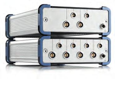
18 Multi-channel power probe Power consumption is a major concern in the Internet of things (IoT) world and for a lot of consumer electronics devices. The R&S RT-ZVC multi-channel power probe offers up to four voltage and four current channels with 18-bit resolution for high dynamic range current and voltage measurements. With up to two R&S RT-ZVC probes supported on a single R&S RTE or R&S RTO oscilloscope, it is possible to analyze eight high dynamic range voltage and eight high dynamic range current signals in parallel with signals captured by the oscilloscope. To optimize the battery life of embedded devices, the device's active, sleep and hibernate current consumption needs to be balanced. While active current consumption can reach levels of tens or hundreds of ma, sleep currents are often as low as several µa, but they still significantly influence battery life since devices are in sleep mode most of the time. Very high dynamic range with 18-bit ADC resolution With up to four current and four voltage input channels, each with 18-bit ADC resolution, the R&S RT-ZVC02/ -ZVC04 multi-channel power probe provides the dynamic range needed to analyze current consumption in all mobile device activity phases. Internal and external shunt current measurement with switchable sensitivity Three built-in shunts and an external shunt mode in combination with switchable gain factors lets you optimize the input current range. Differential inputs provide floating measurements within an input voltage operating window of ±15 V. Settings are fully controlled from the oscilloscope user interface. 18 Probes_accessories_digital_oscilloscopes_bro_en_ _v1000.indd :18:57


19 High bandwidth with flexible filtering for noise reduction Measure up to eight power rails at the same time with highest accuracy A bandwidth of 1 MHz and a sampling rate of 5 Msample/s allows you to capture fast current pulses. To analyze the overall power consumption of battery powered devices, the very low sleep-mode currents have to be captured at the same time. For very high dynamic range measurements, the integrated low-pass filter reduces the bandwidth down to 5 khz and minimizes overall system noise. One R&S RTE or R&S RTO digital oscilloscope supports up to two R&S RT-ZVC current probes so that it is possible to observe eight power domains in parallel with a DC accuracy of 0.1 % for voltage measurements and 0.2 % for current measurements. Ramp-up processes and power rail tolerances can easily be tested with this probe. The oscilloscope's SCPI remote control enables automatic testing. Digital acquisition system Current ranges Digital backend (4 in total) Lowpass Deskew 5 Msample/s A/D I 18 bit 5 Msample/s Shunt ±4.5 µa; ±45 µa 10 kω ±4.5 ma; ±45 ma 10 Ω ±4.5 A; ±10 A 10 mω ±45 mv 1); ±450 mv 1) external Current range depends on shunt value. 1) Trigger I Analog frontend V A/D V 18 bit 5 Msample/s Low-gain mode Voltage ranges The R&S RT-ZVC probe's digital acquisition system provides 18-bit resolution, a 5 Msample/s sampling rate and 1 MHz bandwidth. Each voltage and current input pair forms a high dynamic range power measurement system. ±1.88 V ±3.75 V ±7.5 V ±15 V 12 ma Voltage at DUT 30 µa Current consumption of DUT Zoom in µa range Instantaneous power consumption The R&S RT-ZVC probe provides an extraordinarily high dynamic range for measuring both active state currents and sleep currents, in this example 12 ma and 30 µa. Automated measurements make it possible to calculate the total energy consumption. Rohde & Schwarz Probes and accessories 19 Probes_accessories_digital_oscilloscopes_bro_en_ _v1000.indd :18:57

 can easily be captured and analyzed.")


20 Very low-noise frontend for measuring sensor signals The extraordinarily high dynamic range and low-noise design of the R&S RT-ZVC probe enables clear measurement of small sensor signals. Maximum sensitivity can be achieved by using the current inputs in external shunt mode which results in 18-bit resolution at 45 mv full-scale differential input voltage. A cardiac voltage pulse with a signal level of only 200 µv (Vpp) can easily be captured and analyzed. Flexible connectivity options for every application The R&S RT-ZVC multi-channel power probe comes with a set of high-quality pin connector cables and solder-in leads to connect the probe in typical embedded electronics measurement scenarios. 4 mm connector cables with different lengths are optionally available as are BNC type connector cables for connecting standard oscilloscope voltage and current probes to extend the voltage and current measurement range. Small signals such as a 200 µv cardiac pulse can easily be measured. Standard accessories include PCB connector cables for each channel and 4 mm cables with different lengths and BNC connector cables are option- solder-in leads. ally available. 20 Probes_accessories_digital_oscilloscopes_bro_en_ _v1000.indd :19:00
21 Model Input channels Bandwidth/ sampling rate Resolution Input impedance Full-scale input range R&S RT-ZVC02 2 current, 2 voltage 4 current, 4 voltage 1 MHz/ 5 Msample/s 18-bit ±15 V Voltage ±1.88 V ±3.75 V ±7.5 V ±15 V Current (internal shunt) 10 kω: ±4.5 µa, ±45 µa, 10 Ω: ±4.5 m, ±45 ma, 10 mω: ±4.5 A, ±10 A Current (external shunt, voltage range) ±45 mv, ±450 mv (all channels) R&S RT-ZVC04 Voltage channels: 10 MΩ 48 pf Current channels: 1 MΩ shunt resistor Common mode input voltage range Order No Accessory Comment Order No R&S RT-ZA30 Extended cable set for R&S RT-ZVC, PCB probing, 1 current and 1 voltage lead, length: 32 cm R&S RT-ZA31 Extended cable set for R&S RT-ZVC, 4 mm probing, 1 current and 1 voltage lead, length: 32 cm R&S RT-ZA33 Oscilloscope interface cable for R&S RT-ZVC (included with R&S RT-ZVC02/-ZVC04, /.04) R&S RT-ZA34 Extended cable set for R&S RT-ZVC, 4 mm probing, 1 current and 1 voltage lead, length: 1 m R&S RT-ZA35 Extended cable set for R&S RT-ZVC, PCB probing, 1 current and 1 voltage lead, length: 1 m R&S RT-ZA36 Solder-in cable set for R&S RT-ZVC, 4 current and voltage solder-in cables, solder-in pins R&S RT-ZA37 Extended cable set for R&S RT-ZVC, BNC connector, 1 current and 1 voltage lead, length: 16 cm R&S RTE-B1E Digital extension port for R&S RT-ZVC usage with the R&S RTE digital oscilloscope (included with R&S RTE-B1E) R&S RTO-B1E Digital extension port for R&S RT-ZVC usage with the R&S RTO digital oscilloscope (included in R&S RTO-B1E) Rohde & Schwarz Probes and accessories 21 Probes_accessories_digital_oscilloscopes_bro_en_ _v1000.indd :19:00

22 High-voltage probes The Rohde & Schwarz portfolio of high-voltage probes includes single-ended and differential probes for root mean square (RMS) voltages up to 1000 V for applications up to measurement category CAT II or CAT III. High voltages require special safety precautions Measuring voltages > 33 V (RMS)/46 V (Vp) requires special safety precautions in line with the European Low Voltage Directive. These include protective measures such as protection against accidental contact for all metal parts not connected to protective ground and protection against transient overvoltages through sufficient clearance and creepage distances. The dimensioning of these protective measures determines the measurement category and the field of application for the probe. Single-ended passive probes for RMS voltages up to 1000 V (CAT II) Rohde & Schwarz offers two probes for single-ended measurements at high voltages, the R&S RT-ZH10 and the R&S RT-ZH11. These differ in their attenuation factors of 100:1 and 1000:1, respectively. The probe with the best attenuation for maximum sensitivity can be R&S RT-ZH10 high-voltage, single-ended probe with extensive set of accessories. Maximum pulse peak voltage as a function of the RMS voltage RT-ZH10 CAT I Maximum pulse peak voltage in V AC voltage (RMS) or DC voltage in V Overview of measurement categories CAT 0 through CAT IV CAT 0 CAT II CAT III CAT IV + Power supply Socket Main fuse Transformer The probe design determines its area of application and the maximum rated voltage against protective ground. 22 Probes_accessories_digital_oscilloscopes_bro_en_ _v1000.indd :19:01
 and when used exclusively for pulse measurements for peak voltages of up to 6000 V (CAT I).")
23 selected to match the input voltage being measured. Rohde & Schwarz oscilloscopes automatically detect the attenuation factor. Both probes are designed for RMS voltages up to 1000 V (CAT II) and when used exclusively for pulse measurements for peak voltages of up to 6000 V (CAT I). Accessories include safety alligator clips, rigid and spring-loaded tips and protection caps. High-voltage differential probe for RMS voltages up to 1000 V (CAT III) Floating measurements are sometimes required during measurements on power electronics. Rohde & Schwarz offers the R&S RT-ZD01 high-voltage differential probe for measuring RMS voltages up to 1000 V (CAT III). When used with the R&S RTO and R&S RTM digital oscilloscopes, this probe can be easily selected from the menu as a predefined probe. Power is supplied via the oscilloscope's USB port. The R&S RT-ZD01 has a high input impedance of 8 MΩ and an input capacitance of 3.5 pf, ensuring low loading on the DUT. The selectable attenuation factor of 1:100 or 1:1000 allows optimal matching to the input voltage swing being measured, and also provides maximum vertical resolution on the oscilloscope. The wide common mode dynamic range of ±1400 V can be used for both attenuation factors. Dynamic range and voltage display R&S RT-ZD01 high-voltage differential probe: safe measurement up to 1000:1 100:1 Input voltage range Vdiff = +140 V Vdiff = 140 V 0V Vdiff = 1400 V 1400 V Vdiff = V category CAT III. Negative Positive input voltage limit Negative Positive input voltage limit 1400 V Model Input voltage referenced to ground at positive input Input voltage referenced to ground at negative input Input voltage range Bandwidth Attenuation factor Input impedance Dynamic range Comment Order No. R&S RT-ZH MHz 100:1 100 MΩ 6.5 pf 850 V (RMS) R&S RT-ZH MHz 100:1 50 MΩ 7.5 pf 1 kv (RMS) 1 kv (RMS) (CAT II) R&S RT-ZH MHz 1000:1 50 MΩ 7.5 pf 1 kv (RMS) 1 kv (RMS) (CAT II) Passive Active, differential R&S RT-ZD MHz 1 MΩ 3.5 pf ±20 V BNC interface, 50 Ω output R&S RT-ZD MHz 200 kω 1 pf ±15 V BNC interface, 50 Ω output R&S RT-ZD MHz 100:1/1000:1 (selectable) 8 MΩ 3.5 pf ±140 V/ ±1400 V 1 kv (RMS) (CAT III) Rohde & Schwarz Probes and accessories 23 Probes_accessories_digital_oscilloscopes_bro_en_ _v1000.indd :19:02

.")
24 Current probes Rohde & Schwarz current probes are available in different versions: compact, battery-operated probes for industrial applications to measure currents up to 1000 A and high-precision probes for lab applications, with bandwidths up to 120 MHz and a sensitivity of 1 V/A. DC and AC measurements without circuit interruption The R&S RT-ZC10 and the R&S RT-ZC20 current probes precisely measure direct and alternating current without interrupting the power circuit for the measurement. The extra-large opening on the R&S RT-ZC10 accommodates conductors of up to 20 mm in diameter. The R&S RT-ZC10 can measure peak currents up to 300 A (500 A for a single pulse). When measuring low-amplitude, high-frequency currents, the more compact R&S RT-ZC20 with a measurement bandwidth of 100 MHz is ideal. Robust design and easy operation Rohde & Schwarz current probes are characterized by their robust design and easy operation. The degauss and offset correction is easily performed directly at the probe connector. The compact R&S RT-ZA13 probe power supply supplies up to four current probes. The current probes can be selected as predefined probes on the R&S RTO and R&S RTM digital oscilloscopes. R&S RT-ZC20B current probe with Rohde & Schwarz probe interface (100 MHz, 30 A (RMS)). External power supply for up to four current probes. 24 Probes_accessories_digital_oscilloscopes_bro_en_ _v1000.indd :19:03

25 Easy deskewing for simultaneous current and voltage measurements For meaningful measurements on power electronics, there must be no time delay (skew) between the current and the voltage measurements. The R&S RT-ZF20 power deskew and calibration test fixture provides a variety of test signals that can be used to easily compensate for the skew between Rohde & Schwarz current and voltage probes. Power to the power deskew and calibration test fixture is supplied via the oscilloscope's USB port. R&S RT-ZF20 power deskew and calibration test fixture: easy deskewing for measurements on power electronics. Model Bandwidth Sensitivity Dynamic range R&S RT-ZC02 20 khz R&S RT-ZC khz 0.01 V/A, V/A 0.1 V/A R&S RT-ZC05B 2 MHz 0.01 V/A Rise time Comment Order No. ±200 A, ±2000 A 5 µs battery powered ±30 A 1 µs battery powered A (RMS), 700 A (peak) 150 A (RMS) ±300 A (peak), ±500 A (peak) (single pulse) 30 A (RMS) ±50 A (peak) 175 ns power supply via Rohde & Schwarz probe interface power supply via R&S RT-ZA ns power supply via Rohde & Schwarz probe interface ns power supply via Rohde & Schwarz probe interface power supply via R&S RT-ZA power supply via Rohde & Schwarz probe interface power supply via R&S RT-ZA power deskew and calibration test fixture external power s upply for up to four Rohde & Schwarz current probes Probes R&S RT-ZC10 10 MHz 0.01 V/A R&S RT-ZC10B 10 MHz 0.01 V/A R&S RT-ZC15B 50 MHz 0.1 V/A R&S RT-ZC MHz 0.1 V/A 3.5 ns R&S RT-ZC20B 100 MHz 0.1 V/A 3.5 ns R&S RT-ZC MHz 1 V/A 5 A (RMS) 7.5 A (peak) 35 ns 2.9 ns K K K02 Accessories R&S RT-ZF20 R&S RT-ZA Rohde & Schwarz Probes and accessories 25 Probes_accessories_digital_oscilloscopes_bro_en_ _v1000.indd :19:05

26 EMC near-field probes Powerful E and H near-field probes for the frequency range from 9 khz to 3 GHz with optional preamplifier expand the application range of the R&S RTO digital oscilloscopes to include EMI debugging. R&S RTO digital oscilloscope's powerful FFT analysis function Versatile near-field probe sets Near-field probes are a tool used to analyze EMC problems in electronic circuits and to identify their causes. Rohde & Schwarz offers the versatile R&S HZ-15 near-field probe set that includes E-field and H-field probes for use with oscilloscopes, signal and spectrum analyzers and EMI test receivers. The R&S HZ-15 passive probe set is the right choice for diagnosing EMC problems on printed boards. Designed for a frequency range of 30 MHz to 3 GHz, the R&S HZ-15 permits the detection of EMI < 30 MHz at reduced sensitivity. The compact design facilitates localization of EMI sources down to the individual conductors. The optional R&S HZ-16 preamplifier offers 20 db gain for greater sensitivity in the frequency range from 100 khz to 1 GHz. The R&S RTO digital oscilloscope's powerful FFT function permits for the first time debugging of EMI problems using an oscilloscope. Developers now have a cost-effective solution for EMI debugging right on their lab bench. Unwanted EMI can be displayed simultaneously in both the time and frequency domain, speeding up debugging. Direct acquisition and analysis of sporadically occurring EMI thanks to the R&S RTO digital oscilloscope's powerful spectrum analysis function. Model Frequency range Comment Order No. 30 MHz to 3 GHz compact E and H near-field probe set khz to 3 GHz preamplifier 3 GHz, 20 db, power adapter 100 V to 230 V Near-field probe R&S HZ-15 Accessories R&S HZ Probes_accessories_digital_oscilloscopes_bro_en_ _v1000.indd :19:05
Probes and accessories for Rohde & Schwarz oscilloscopes
 Product Brochure Version 13.01 Probes and accessories for Rohde & Schwarz oscilloscopes Probes_and_accessories_bro_en_3606-8866-12_v1301.indd 1 16.07.2018 16:25:43 Probes and accessories for Rohde & Schwarz
R&S RT-ZM Modular Probe System
 RT-ZMxx_fly_3607-5690-32_v0102.indd 3 roduct Flyer 01.02 3607.5690.32 01.02 D 1 en Test & Measurement R&S RT-ZM Modular robe System 08.11.2016 16:20:21 Addressing high-speed probing challenges Serv The
R&S RT-Zxx High-Bandwidth Probes Specifications
 R&S RT-Zxx High-Bandwidth Probes Specifications Test & Measurement Data Sheet 14.00 CONTENTS Definitions... 3 Probe/oscilloscope chart... 4 R&S RT-ZZ80 transmission line probe... 5 R&S RT-ZS10/-ZS10E/-ZS20/-ZS30
R&S RT-Zxx High-Voltage and Current Probes Specifications
 R&S RT-Zxx High-Voltage and Current Probes Specifications Test & Measurement Data Sheet 14.00 CONTENTS Definitions... 3 Probe/oscilloscope chart... 4 R&S RT-ZH10/-ZH11 high-voltage probes... 5 R&S RT-ZD01
R&S RT-Zxx Oscilloscope Adapters Specifications. Data Sheet V23.00
 R&S RT-Zxx Oscilloscope Adapters Specifications Data Sheet V23.00 CONTENTS Definitions... 3 Probe/adapter chart... 4 R&S RT-Z2T probe interface adapter... 7 R&S RT-ZA9 probe box to N/USB adapter... 9 Ordering
Oscilloscope innovation. Measurement confidence.
 Oscilloscope innovation. Measurement confidence. www.rohde-schwarz.com/oscilloscopes Applications Signal integrity The R&S RTP oscilloscopes offer various analysis and measurement tools for analyzing the
R&S RT-Zxx Standard Probes Specifications
 R&S RT-Zxx Standard Probes Specifications Test & Measurement Data Sheet 16.00 CONTENTS Definitions... 3 Probe/oscilloscope chart... 4 R&S RT-ZP03 passive probe... 5 R&S RT-ZP05(S) passive probe... 8 R&S
Oscilloscope innovation. Measurement confidence.
 Oscilloscope innovation. Measurement confidence. www.rohde-schwarz.com/oscilloscopes Applications Power analysis Analysis tools help developers verify and debug current and voltage supply circuits. The
Max. sampling rate (realtime) channel. interleaved. 1 Gsample/s. interleaved. 2.5 Gsample/s per channel 5 Gsample/s. 5 Gsample/s per channel
 channel. interleaved. 1 Gsample/s. interleaved. 2.5 Gsample/s per channel 5 Gsample/s. 5 Gsample/s per channel") /designation Bandwidth ( db) Number of s Max. sampling rate (realtime) Memory depth Input sensitivity R&S HMO1002 digital oscilloscope 50 MHz 70 MHz 100 MHz 2 s 512 Msample/s per 1 Gsample/s 512 ksample
/designation Bandwidth ( db) Number of s Max. sampling rate (realtime) Memory depth Input sensitivity R&S HMO1002 digital oscilloscope 50 MHz 70 MHz 100 MHz 2 s 512 Msample/s per 1 Gsample/s 512 ksample
R&S RT-ZVCxx Multi-Channel Power Probe Specifications
 R&S RT-ZVCxx Multi-Channel Power Probe Specifications year Data Sheet Version 03.00 CONTENTS Definitions... 3 Probe characteristics... 4 Voltmeter... 4 Amperemeter... 5 Digital backend... 7 R&S CMWrun
R&S RT-ZF20 Power Deskew Fixture User Manual
 R&S RT-ZF20 Power Deskew Fixture User Manual (B00X2) User Manual Test & Measurement 1800.0040.02 04 This manual describes the following R&S RT-ZF models: R&S RT-ZF20 (1800.0004.01) 2016 Rohde & Schwarz
R&S RTM Digital Oscilloscope Scope of the art
 RTM_bro_en_3606-8066-12_v0600.indd 1 Product Brochure 06.00 Test & Measurement R&S RTM Digital Oscilloscope Scope of the art 16.12.2015 10:16:54 R&S RTM Digital Oscilloscope At a glance Ease of use combined
Product Brochure Version HZ-15_16_17_bro_en_ _v0100.indd 1
 Product Brochure Version 1. R&S HZ-15/R&S HZ-17 Probe Sets R&S HZ-16 Preamplifier E and H near-field emission measurements with test receivers, spectrum analyzers and oscilloscopes HZ-15_16_17_bro_en_5213-6687-12_v1.indd
2 MHz Lock-In Amplifier
 2 MHz Lock-In Amplifier SR865 2 MHz dual phase lock-in amplifier SR865 2 MHz Lock-In Amplifier 1 mhz to 2 MHz frequency range Dual reference mode Low-noise current and voltage inputs Touchscreen data display
WAVEJET 300 SERIES OSCILLOSCOPES. New Cover to Come. Unmatched Performance, Portability, and Value
 WAVEJET 300 SERIES OSCILLOSCOPES New Cover to Come Unmatched Performance, Portability, and Value ALL THE TOOLS YOU NEED Automatic Measurements Save time making measurements on your signals by using the
WAVEJET 300 SERIES OSCILLOSCOPES. Unmatched Performance, Portability, and Value
 WAVEJET 300 SERIES OSCILLOSCOPES Unmatched Performance, Portability, and Value 1 WAVEJET 300 SERIES Unique Capabilities in a Low Bandwidth Oscilloscope The WaveJet 300 Series features unmatched performance
Dynamic re-referencing Microvolt-level measurements with the R&S RTO oscilloscopes
 RTO_app-bro_3607-2855-92_v0100.indd 1 Microvolt-level measurements with the R&S RTO Test & Measurement Application Brochure 01.00 Dynamic re-referencing Microvolt-level measurements with the R&S RTO oscilloscopes
Model 7330 Signal Source Analyzer Dedicated Phase Noise Test System V1.02
 Model 7330 Signal Source Analyzer Dedicated Phase Noise Test System V1.02 A fully integrated high-performance cross-correlation signal source analyzer from 5 MHz to 33+ GHz Key Features Complete broadband
MSO-28 Oscilloscope, Logic Analyzer, Spectrum Analyzer
 Link Instruments Innovative Test & Measurement solutions since 1986 Store Support Oscilloscopes Logic Analyzers Pattern Generators Accessories MSO-28 Oscilloscope, Logic Analyzer, Spectrum Analyzer $ The
Benefits of the R&S RTO Oscilloscope's Digital Trigger. <Application Note> Products: R&S RTO Digital Oscilloscope
 Benefits of the R&S RTO Oscilloscope's Digital Trigger Application Note Products: R&S RTO Digital Oscilloscope The trigger is a key element of an oscilloscope. It captures specific signal events for detailed
R&S RTA4000 Oscilloscope Power of ten
 R&S RTA4000 Oscilloscope Power of ten 200 MHz to 1 GHz 10-bit ADC 1 Gsample standard memory Product Brochure Version 01.01 year RTA4000_bro_en_5215-1776-12_v0101.indd 1 19.12.2017 13:49:04 R&S RTA4000
7000 Series Signal Source Analyzer & Dedicated Phase Noise Test System
 7000 Series Signal Source Analyzer & Dedicated Phase Noise Test System A fully integrated high-performance cross-correlation signal source analyzer with platforms from 5MHz to 7GHz, 26GHz, and 40GHz Key
Troubleshooting EMI in Embedded Designs White Paper
 Troubleshooting EMI in Embedded Designs White Paper Abstract Today, engineers need reliable information fast, and to ensure compliance with regulations for electromagnetic compatibility in the most economical
R&S RTE Digital Oscilloscope Scope of the art
 RTE_bro_en_3606-9033-12.indd 1 Product Brochure 01.00 Test & Measurement R&S RTE Digital Oscilloscope Scope of the art 03.03.2014 08:57:33 R&S RTE Digital Oscilloscope At a glance Besides the cursor functions
R&S RTO Digital Oscilloscope Scope of the art
 Test & Measurement Product Brochure 05.00 R&S RTO Digital Oscilloscope Scope of the art R&S RTO Digital Oscilloscope At a glance The R&S RTO oscilloscopes combine excellent signal fidelity, high acquisition
PicoScope 6407 Digitizer
 YE AR PicoScope 6407 Digitizer HIGH PERFORMANCE USB DIGITIZER Programmable and Powerful 1 GHz bandwidth 1 GS buffer size 5 GS/s real-time sampling Advanced digital triggers Built-in function generator
4 MHz Lock-In Amplifier
 4 MHz Lock-In Amplifier SR865A 4 MHz dual phase lock-in amplifier SR865A 4 MHz Lock-In Amplifier 1 mhz to 4 MHz frequency range Low-noise current and voltage inputs Touchscreen data display - large numeric
Meeting your needs R&S RTO2000 Digital Oscilloscope
 Meeting your needs R&S RTO2000 Digital Oscilloscope Multi Domain 3607.2684.32 03.00 PDP 1 en Turn your signals into success. RTO2000_fly_en_3607-2684-32_v0300.indd 3 01.02.2017 11:35:10 Best oscilloscope
Portable Performance for Debug and Validation
 WaveJet 300A Oscilloscopes 100 MHz 500 MHz Portable Performance for Debug and Validation A UNIQUE TOOLSET FOR PORTABLE OSCILLOSCOPES Key Features 100 MHz, 200 MHz, 350 MHz and 500 MHz bandwidths Sample
R&S ZVA110 Vector Network Analyzer Specifications
 ZVA110_dat-sw_en_5214-4813-22_cover.indd 1 Data Sheet 04.00 Test & Measurement R&S ZVA110 Vector Network Analyzer Specifications 15.11.2013 14:42:28 CONTENTS Definitions... 3 Specifications... 4 Overview...
PicoScope 6407 Digitizer
 YE AR HIGH PERFORMANCE USB DIGITIZER Programmable and Powerful 1 GHz bandwidth 1 GS buffer size 5 GS/s real-time sampling Advanced digital triggers Built-in function generator USB-connected Signals Analysis
Synthesized Clock Generator
 Synthesized Clock Generator CG635 DC to 2.05 GHz low-jitter clock generator Clocks from DC to 2.05 GHz Random jitter
R&S RTM3000 Oscilloscope Power of ten
 R&S RTM3000 Oscilloscope Power of ten 100 MHz to 1 GHz 10-bit ADC 80 Msample standard memory 10.1" capacitive touchscreen Product Brochure Version 03.00 year RTM3000_bro_en_5214-9144-12_v0300.indd 1 30.11.2017
R&S RTO Digital Oscilloscopes Scope of the art
 R&S RTO Digital Oscilloscopes Scope of the art Test & Measurement Product Brochure 01.00 R&S RTO Digital Oscilloscopes At a glance The R&S RTO oscilloscopes combine excellent signal fidelity, high acquisition
Digital Storage Oscilloscopes 2550 Series
 Data Sheet Digital Storage Oscilloscopes 2550 Series The 2550 series digital storage oscilloscopes provide high performance and value in 2-channel and 4-channel configurations. With bandwidth from 70 MHz
R&S RTO Digital Oscilloscope Scope of the art
 RTO_bro_en_5214-2327-12.indd 1 Product Brochure 15.00 Test & Measurement R&S RTO Digital Oscilloscope Scope of the art 05.11.2014 13:20:21 R&S RTO Digital Oscilloscope At a glance The R&S RTO oscilloscopes
OPTICAL POWER METER WITH SMART DETECTOR HEAD
 OPTICAL POWER METER WITH SMART DETECTOR HEAD Features Fast response (over 1000 readouts/s) Wavelengths: 440 to 900 nm for visible (VIS) and 800 to 1700 nm for infrared (IR) NIST traceable Built-in attenuator
Expect to Make Waves.
 Expect to Make Waves. The New Oscilloscope Large 10.4" LCD touch screen Long capture time Extensive communication capabilities www.lecroy.com The New Oscillos From its large 10.4" LCD touch screen to its
Spectrum Analyzer 1.6 GHz 3 GHz R&S HMS-X
 HMS-X_bro_de-en_3607-0181-3X_v0200.indd 1 Product Brochure 02.00 Test & Measurement Spectrum Analyzer 1.6 GHz 3 GHz R&S HMS-X 15.03.2016 15:24:06 1 Basic Unit + 3 Options Key facts Frequency range: 100
R&S RTE Digital Oscilloscope Scope of the art
 Test & Measurement Product Brochure 04.00 R&S RTE Digital Oscilloscope Scope of the art R&S RTE Digital Oscilloscope At a glance Truly uncompromised in performance and impressively user-friendly that s
Analyze Frequency Response (Bode Plots) with R&S Oscilloscopes Application Note
 with R&S Oscilloscopes Application Note") Analyze Frequency Response (Bode Plots) with R&S Oscilloscopes Application Note Products: R&S RTO2002 R&S RTO2004 R&S RTO2012 R&S RTO2014 R&S RTO2022 R&S RTO2024 R&S RTO2044 R&S RTO2064 This application
Analyze Frequency Response (Bode Plots) with R&S Oscilloscopes Application Note Products: R&S RTO2002 R&S RTO2004 R&S RTO2012 R&S RTO2014 R&S RTO2022 R&S RTO2024 R&S RTO2044 R&S RTO2064 This application
HP 71910A and 71910P Wide Bandwidth Receiver Technical Specifications
 HP 71910A and 71910P Wide Bandwidth Receiver Technical Specifications 100 Hz to 26.5 GHz The HP 71910A/P is a receiver for monitoring signals from 100 Hz to 26.5 GHz. It provides a cost effective combination
Measuring with digital storage oscilloscopes
 Markus Reil, Rainer Wagner 2.2016 1MAA265-1e Educational note Measuring with digital storage oscilloscopes Educational note Products: ı R&S HMO1002 This educational note covers the theory and practice
2 MHz Lock-In Amplifier
 2 MHz Lock-In Amplifier SR865 2 MHz dual phase lock-in amplifier SR865 2 MHz Lock-In Amplifier 1 mhz to 2 MHz frequency range Low-noise current and voltage inputs Touchscreen data display - large numeric
PRELIMINARY INFORMATION. Professional Signal Generation and Monitoring Options for RIFEforLIFE Research Equipment
 Integrated Component Options Professional Signal Generation and Monitoring Options for RIFEforLIFE Research Equipment PRELIMINARY INFORMATION SquareGENpro is the latest and most versatile of the frequency
Product Brochure Version R&S ENV A Four-Line V-Network RFI voltage measurements at high currents
 Product Brochure Version 01.00 200 A Four-Line V-Network RFI voltage measurements at high currents ENV4200_bro_en_5214-8390-12_v0100.indd 1 26.01.2017 15:22:54 200 A Four-Line V-Network At a glance The
G4500. Portable Power Quality Analyser. Energy Efficiency through power quality
 G4500 Portable Power Quality Analyser Energy Efficiency through power quality The BlackBox portable series power quality analyser takes power quality monitoring to a whole new level by using the revolutionary
Datasheet SHF A
 SHF Communication Technologies AG Wilhelm-von-Siemens-Str. 23D 12277 Berlin Germany Phone +49 30 772051-0 Fax ++49 30 7531078 E-Mail: sales@shf.de Web: http://www.shf.de Datasheet SHF 19120 A 2.85 GSa/s
Signal Conditioners. Highlights. Battery powered. Line powered. Multi-purpose. Modular-style. Multi-channel. Charge & impedance converters
 Signal Conditioners Highlights Battery powered Line powered Multi-purpose Modular-style Multi-channel Charge & impedance converters Industrial charge amplifiers & sensor simulators PCB Piezotronics, Inc.
Product Brochure Version R&S RSC Step Attenuator Where precise signal levels count
 Product Brochure Version 02.00 Step Attenuator Where precise signal levels count RSC_bro_en_5214-4413-12_v0200.indd 1 07.09.2018 10:36:40 Step Attenuator At a glance The is a switchable, mechanical step
What to look for when choosing an oscilloscope
 What to look for when choosing an oscilloscope Alan Tong (Pico Technology Ltd.) Introduction For many engineers, choosing a new oscilloscope can be daunting there are hundreds of different models to choose
R&S RTM3000 Oscilloscope Power of ten
 R&S RTM3000 Oscilloscope Power of ten 100 MHz to 1 GHz 10-bit ADC 80 Msample standard memory 10.1" capacitive touchscreen Product Brochure Version 04.02 year RTM3000_bro_en_5214-9144-12_v0402.indd 1 01.03.2018
R&S RTM3000 Oscilloscope Power of ten
 R&S RTM3000 Oscilloscope Power of ten 100 MHz to 1 GHz 10-bit ADC 80 Msample standard memory 10.1" capacitive touchscreen Product Brochure Version 04.00 year RTM3000_bro_en_5214-9144-12_v0400.indd 1 11.01.2018
Scope of the art Scope Rider Handheld digital oscilloscope
 Scope of the art Scope Rider Handheld digital oscilloscope Lab performance in a rugged and portable design 60 MHz to 500 MHz Isolated, CAT IV Invest 2 minutes and you ll never look back. Scope Rider Experience
Efficient analysis of power and signal integrity and EMC
 Efficient analysis of power and signal integrity and EMC Electronic design Test and measurement solutions 5215.2914.32 PDP 1 en Turn your signals into success. 21793_002_Power-Electronics_Solution_fly_en_170627_v0101.indd
R&S RTM3000 Oscilloscope Power of ten
 100 MHz to 1 GHz 10-bit ADC 80 Msample standard memory 10.1" capacitive touchscreen year Product Brochure Version 03.00 R&S RTM3000 Oscilloscope Power of ten R&S RTM3000 Oscilloscope At a glance Designed
Bluetooth Tester CBT. Specifications. Specifications. Version January 2006
 Specifications Version 03.00 Bluetooth Tester CBT January 2006 Specifications CONTENTS UNIT SPECIFICATIONS...3 TIMEBASE TCXO...3 REFERENCE FREQUENCY INPUT...3 RF GENERATOR...3 RF ANALYZER...5 Power meter
R&S ZVA-Zxx Millimeter-Wave Converters Specifications
 ZVA-Zxx_dat-sw_en_5214.2033.22_umschlag.indd 1 Data Sheet 13.00 Test & Measurement R&S ZVA-Zxx Millimeter-Wave Converters Specifications 28.01.2013 15:08:06 CONTENTS General information... 3 Definitions...
EX-IQ-Box Digital Signal Interface Module Specifications
 Test & Measurement Data Sheet 01.01 EX-IQ-Box Digital Signal Interface Module Specifications Introduction The R&S EX-IQ-Box is a digital interface module that provides flexible digital baseband inputs
PicoScope PC Oscilloscopes. User's Guide. ps2203.en r4 Copyright Pico Technology Limited. All rights reserved.
 PicoScope 2203 PC Oscilloscopes User's Guide PicoScope 2203 User's Guide I Contents 1 Welcome...1 2 Introduction...2 1 Using this guide 2 Safety symbols 3 Safety warning 4 FCC notice 5 CE notice...2...2...3...4...4...5
R&S RTB2000 Digital Oscilloscope Power of ten
 Product Brochure Version 03.00 R&S RTB2000 Digital Oscilloscope Power of ten 70 MHz to 300 MHz 10-bit ADC 10 Msample standard memory 10.1" capacitive touchscreen year R&S RTB2000 Digital Oscilloscope At
R&S ZVA-Zxx Millimeter-Wave Converters Specifications
 R&S ZVA-Zxx Millimeter-Wave Converters Specifications Data Sheet Version 19.00 CONTENTS Definitions... 3 General information... 4 Specifications... 5 Test port... 5 Source input (RF IN)... 5 Local oscillator
PROGRAMMABLE DC SOURCE VIEW RECORDERS Programmable DC Source FEATURES
 Programmable DC Source Sink and Source Capability Conventional DC sources usually have the function of power supply (source) only without power absorption (sink) function. In addition to the source function,
Agilent 5345A Universal Counter, 500 MHz
 Agilent 5345A Universal Counter, 500 MHz Data Sheet Product Specifications Input Specifications (pulse and CW mode) 5356C Frequency Range 1.5-40 GHz Sensitivity (0-50 deg. C): 0.4-1.5 GHz -- 1.5-12.4 GHz
R&S ETH Handheld TV Analyzer Portable DVB-T/H signal analysis up to 3.6/8 GHz
 R&S ETH Handheld TV Analyzer Portable DVB-T/H signal analysis up to 3.6/8 GHz Broadcast Product Brochure 02.00 R&S ETH Handheld TV Analyzer At a glance The R&S ETH handheld TV analyzer was specially designed
R&S RTC1000 Oscilloscope Great value
 R&S RTC1000 Oscilloscope Great value 50 MHz to 300 MHz Two channels Product Brochure Version 0.00 year RTC1000_bro_en_3607-87-1_v000.indd 1 10.01.018 1:5:16 R&S RTC1000 Oscilloscope At a glance High sensitivity,
R&S RTB2000 Digital Oscilloscope Power of ten
 R&S RTB2000 Digital Oscilloscope Power of ten 70 MHz to 300 MHz 10-bit ADC 10 Msample standard memory 10.1" capacitive touchscreen Product Brochure Version 04.00 year RTB2000_bro_en_3607-4270-12_v0400.indd
14 GHz, 2.2 kw KLYSTRON GENERATOR GKP 22KP 14GHz WR62 3x400V
 14 GHz, 2.2 kw KLYSTRON GENERATOR GKP 22KP 14GHz WR62 3x400V With its characteristics of power stability independent of the load, very fast response time when pulsed (via external modulated signal), low
Application Note AN-LD09 Rev. B Troubleshooting Low Noise Systems. April, 2015 Page 1 NOISE MEASUREMENT SYSTEM BASELINES INTRODUCTION
 Troubleshooting Low Noise Systems April, 2015 Page 1 INTRODUCTION The exceedingly low level of electronic noise produced by the QCL family of drivers makes narrower linewidths and stable center wavelengths
Oscilloscope Guide Tektronix TDS3034B & TDS3052B
 Tektronix TDS3034B & TDS3052B Version 2008-Jan-1 Dept. of Electrical & Computer Engineering Portland State University Copyright 2008 Portland State University 1 Basic Information This guide provides basic
GFT Channel Digital Delay Generator
 Features 20 independent delay Channels 100 ps resolution 25 ps rms jitter 10 second range Output pulse up to 6 V/50 Ω Independent trigger for every channel Fours Triggers Three are repetitive from three
Meeting Embedded Design Challenges with Mixed Signal Oscilloscopes
 Meeting Embedded Design Challenges with Mixed Signal Oscilloscopes Introduction Embedded design and especially design work utilizing low speed serial signaling is one of the fastest growing areas of digital
R&S RSC Step Attenuator Where precise signal levels count
 Test & Measurement Product Brochure 01.00 Step Attenuator Where precise signal levels count Step Attenuator At a glance The is a switchable, mechanical step attenuator. It is available in various models
Manual Supplement. This supplement contains information necessary to ensure the accuracy of the above manual.
 Manual Title: 9500B Users Supplement Issue: 2 Part Number: 1625019 Issue Date: 9/06 Print Date: October 2005 Page Count: 6 Version 11 This supplement contains information necessary to ensure the accuracy
ScopeMeter 190 Series Specifications
 Seite 1 von 7 ScopeMeter 190 Series Specifications Product Home Features Specifications Models, Options & Accessories Oscilloscope Mode Meter Mode Recorder Mode General Specifications Oscilloscope Mode
Electrical Sampling Modules Datasheet 80E11 80E11X1 80E10B 80E09B 80E08B 80E07B 80E04 80E03 80E03-NV
 Electrical Sampling Modules Datasheet 80E11 80E11X1 80E10B 80E09B 80E08B 80E07B 80E04 80E03 80E03-NV The DSA8300 Series Sampling Oscilloscope, when configured with one or more electrical sampling modules,
Oscilloscopes for debugging automotive Ethernet networks
 Application Brochure Version 01.00 Oscilloscopes for debugging automotive Ethernet networks Oscilloscopes_for_app-bro_en_3607-2484-92_v0100.indd 1 30.07.2018 12:10:02 Comprehensive analysis allows faster
Clamp 200 A AC/DC (+ V AC/DC + Ω)
") PCE-DC1 Clamp meter 200 A AC/DC & Freq. LC display 3 2/3 digits, with backlight measures AC / DC current, AC voltage & frequency Hold function / DC A zero reset function tests voltage without contact automatic
PCE-DC1 Clamp meter 200 A AC/DC & Freq. LC display 3 2/3 digits, with backlight measures AC / DC current, AC voltage & frequency Hold function / DC A zero reset function tests voltage without contact automatic
Switching Solutions for Multi-Channel High Speed Serial Port Testing
 Switching Solutions for Multi-Channel High Speed Serial Port Testing Application Note by Robert Waldeck VP Business Development, ASCOR Switching The instruments used in High Speed Serial Port testing are
18 GHz, 2.2 kw KLYSTRON GENERATOR GKP 24KP 18GHz WR62 3x400V
 18 GHz, 2.2 kw KLYSTRON GENERATOR GKP 24KP 18GHz WR62 3x400V With its characteristics of power stability whatever the load, very fast response time when pulsed (via external modulated signal), low ripple,
Digital Delay / Pulse Generator DG535 Digital delay and pulse generator (4-channel)
") Digital Delay / Pulse Generator Digital delay and pulse generator (4-channel) Digital Delay/Pulse Generator Four independent delay channels Two fully defined pulse channels 5 ps delay resolution 50 ps
Digital Delay / Pulse Generator Digital delay and pulse generator (4-channel) Digital Delay/Pulse Generator Four independent delay channels Two fully defined pulse channels 5 ps delay resolution 50 ps
Process Transmitter RMA 422
 Technical Information TI 072R/24/ae Process Transmitter RMA 422 Multi-functional 1-2 channel top hat DIN rail unit with loop power supply, alarm set point monitoring, mathematics function and 1-2 analog
Advanced Test Equipment Rentals ATEC (2832)
") E stablished 1981 Advanced Test Equipment Rentals www.atecorp.com 800-404-ATEC (2832) Technical Datasheet Scalar Network Analyzer Model 8003-10 MHz to 40 GHz The Giga-tronics Model 8003 Precision Scalar
E stablished 1981 Advanced Test Equipment Rentals www.atecorp.com 800-404-ATEC (2832) Technical Datasheet Scalar Network Analyzer Model 8003-10 MHz to 40 GHz The Giga-tronics Model 8003 Precision Scalar
SingMai Electronics SM06. Advanced Composite Video Interface: HD-SDI to acvi converter module. User Manual. Revision 0.
 SM06 Advanced Composite Video Interface: HD-SDI to acvi converter module User Manual Revision 0.4 1 st May 2017 Page 1 of 26 Revision History Date Revisions Version 17-07-2016 First Draft. 0.1 28-08-2016
Large Area, High Speed Photo-detectors Readout
 Large Area, High Speed Photo-detectors Readout Jean-Francois Genat + On behalf and with the help of Herve Grabas +, Samuel Meehan +, Eric Oberla +, Fukun Tang +, Gary Varner ++, and Henry Frisch + + University
R&S FSW-B512R Real-Time Spectrum Analyzer 512 MHz Specifications
 R&S FSW-B512R Real-Time Spectrum Analyzer 512 MHz Specifications Data Sheet Version 02.00 CONTENTS Definitions... 3 Specifications... 4 Level... 5 Result display... 6 Trigger... 7 Ordering information...
Transcom Instruments. Product Brochure TRANSCOM INSTRUMENTS. Product Brochure. 1
 TRANSCOM INSTRUMENTS Product Brochure Transcom Instruments Product Brochure www.transcomwireless.com 1 T5000 Series Bench-top Vector Network Analyzer Overview T5000 Series Bench-top Vector Network Analyzer
Application Note #63 Field Analyzers in EMC Radiated Immunity Testing
 Application Note #63 Field Analyzers in EMC Radiated Immunity Testing By Jason Galluppi, Supervisor Systems Control Software In radiated immunity testing, it is common practice to utilize a radio frequency
News from Rohde&Schwarz Number 195 (2008/I)
") BROADCASTING TV analyzers 45120-2 48 R&S ETL TV Analyzer The all-purpose instrument for all major digital and analog TV standards Transmitter production, installation, and service require measuring equipment
BROADCASTING TV analyzers 45120-2 48 R&S ETL TV Analyzer The all-purpose instrument for all major digital and analog TV standards Transmitter production, installation, and service require measuring equipment
RIGOL. Data Sheet. DS1000B Series Digital Oscilloscopes DS1074B, DS1104B, DS1204B. Product Overview. Easy to Use Design. Applications.
 RIGOL Data Sheet Product Overview DS1000B series oscilloscopes are designed with four analog channels and 1 external trigger channel, which can capture multi-channel signal simultaneously and meet industrial
R&S FPC1000 Spectrum Analyzer Specifications
 R&S FPC1000 Spectrum Analyzer Specifications year Data Sheet Version 01.00 CONTENTS Definitions... 3 Specifications... 4 Frequency... 4 Sweep time... 4 Bandwidth... 4 Level... 5 Trigger functions... 6
Microwave Counter, Power Meter and DVM in One Portable Package
 Agilent 53140 Series Microwave Counter, Power Meter and DVM in One Portable Package Product Overview Everything you need for the installation and maintenance of microwave links: A choice of frequency counter
Spectrum Analyzer 1.6 GHz 3 GHz HMS-X
 Spectrum Analyzer 1.6 GHz 3 GHz 1 Basic Unit + 3 Options Your Spectrum Analyzer Key facts Frequency range: 100 khz to 1.6 GHz/3 GHz* 1 Spectral purity greater than -100 dbc/hz (at 100 khz) SWEEP from 20
MTI-2100 FOTONIC SENSOR. High resolution, non-contact. measurement of vibration. and displacement
 A worldwide leader in precision measurement solutions MTI-2100 FOTONIC SENSOR High resolution, non-contact measurement of vibration and displacement MTI-2100 Fotonic TM Sensor Unmatched Resolution and
PicoScope 4000 Series PC Oscilloscopes
 PicoScope 4000 Series PC Oscilloscopes User's Guide -1 Contents I Contents 1 Welcome...1 2 Introduction...2 1 Using this guide 2 Safety symbols 3 Safety warning 4 FCC notice 5 CE notice...2...2...2...3...3...3
DIGITAL OSCILLOSCOPES & DIGITAL SCOPES
 7050/7050/70505/7055 Digital Oscilloscopes DL540/DL540L/DL50/DL50L FUNCTIONS SIGL OBSERVATION USING LONG MEMORY Capturing Signals Using Long Memory for Accurate Waveforms The DL50/DL540 can continuously
S op o e p C on o t n rol o s L arni n n i g n g O bj b e j ctiv i e v s
 ET 150 Scope Controls Learning Objectives In this lesson you will: learn the location and function of oscilloscope controls. see block diagrams of analog and digital oscilloscopes. see how different input
Boosting Performance Oscilloscope Versatility, Scalability
 Boosting Performance Oscilloscope Versatility, Scalability Rising data communication rates are driving the need for very high-bandwidth real-time oscilloscopes in the range of 60-70 GHz. These instruments
R&S ZN-Z103 Calibration Unit Specifications. Data Sheet V02.01
 R&S ZN-Z103 Calibration Unit Specifications Data Sheet V02.01 CONTENTS Definitions... 3 Measurement range... 5 Effective system data... 5 General data... 6 Ordering information... 7 2 Rohde & Schwarz R&S
R&S FSW-K54 EMI Measurement Application Detecting and eliminating electromagnetic
 R&S FSW-K54 EMI Measurement Application Detecting and eliminating electromagnetic interference Test & Measurement Product Brochure 01.00 R&S FSW-K54 EMI Measurement Application At a glance The R&S FSW-K54