ENGLISH Creator 2048
|
|
|
- Colin Blankenship
- 6 years ago
- Views:
Transcription


1 MANUAL ENGLISH Creator 2048 V2 Highlite International B.V. Vestastraat EX Kerkrade the Netherlands
2 Table of contents Installation... 3 Unpack... 3 Safety instructions... 3 Connection with the mains... 5 Description of the device... 7 Frontside... 8 Layout... 9 Glossary...10 Installation...11 Set Up and Operation Patching Patch dimmer Patch moving light fixtures View the patching Changing the DMX address of a fixture Deleting a patched fixture Patch Utilities Controlling dimmers and fixtures Selecting fixtures and dimmers for control Changing attributes of the selected fixtures Grouping Stepping through Selected Fixture one at a time The Align function Flip Function Fan Mode Advanced Options Palette Customize palette Palette Page Shared and individual Palette Which attributes are stored in palettes Storing a palette Palette modes Recalling a palette value Delete a Palette Shapes Selecting a shape Shape Parameters Edit a Running Shape Remove a Shape from Fixtures Delete a Shape Relative Shapes and Absolute Shapes Playback Parameters Scenes Creating a Scene Using shapes in Scenes HTP and LTP channels Playing back a Scene Editing a Scene Include function The Off button Copy a Scene Delete a Scene Time
3 5.11 Overlap Priority Chase Programming a chase Running a chase Connecting a chase to the controls Setting speed, crossfade and direction Manually controlling the chase step Add a Step Unfold a Chase for Editing Delete a Chase The global time of a chase Set separate time for a step Advanced Options Overlap Priority CueList Save a CueList Edit a CueList Run a CueList Delete a CueList Copy a CueList Set Global Time Set Special Time for a Step Show Record Record a Show Run a Show Delete a Show Save/Load a show Setup U-Disk Management Wipe Language selection Personality Management Program Record User Settings Update of the IC on the Output PCB System information Update Personality Builder...37 Maintenance...38 Troubleshooting...38 No Light...38 No Response to DMX...38 Product Specifications...39 Dimensions
4 Installation Unpack Immediately upon receiving this product, carefully unpack the carton and check the contents to ensure that all parts are present, and have been received in good condition. Notify the dealer immediately and retain packing material for inspection if any parts appear damaged from shipping or the carton itself shows signs of mishandling. Save the carton and all packing materials. In the event that a fixture must be returned to the factory, it is important that the fixture be returned in the original factory box and packing. Your shipment includes: Showtec Creator 2048 Flight case Power cable (1,5 m) User manual Optional Accessories: Goose-neck lamp (ordercode: 60722) Safety instructions Every person involved with the installation, operation and maintenance of this device has to: be qualified follow the instructions of this manual Before your initial start-up, please make sure that there is no damage caused by transportation. Should there be any, consult your dealer and do not use the device. To maintain perfect condition and to ensure a safe operation, it is absolutely necessary for the user to follow the safety instructions and warning notes written in this manual. Please consider that damages caused by manual modifications to the device are not subject to warranty. This device contains no user-serviceable parts. Refer servicing to qualified technicians only. 3
5 IMPORTANT: The manufacturer will not accept liability for any resulting damages caused by the non-observance of this manual or any unauthorized modification to the device. Never let the power cord come into contact with other cables! Handle the power cord and all connections with the mains with particular caution! Never remove warning or informative labels from the unit. Do not open the device and do not modify the device. Never use anything to cover the ground contact. Never leave any cables lying around. Do not insert objects into air vents. Do not connect this device to a dimmerpack. Do not switch the device on and off in short intervals, as this would reduce the device s life. Do not shake the device. Avoid brute force when installing or operating the device. Never use the device during thunderstorms, unplug the device immediately. Only use device indoors, avoid contact with water or other liquids. Do not touch the device s housing bare-handed during its operation (housing becomes hot). Only operate the device after having familiarized with its functions. Avoid flames and do not put close to flammable liquids or gases. Always keep case closed while operating. Always allow free air space of at least 50 cm around the unit for ventilation. Always disconnect power from the mains, when device is not used or before cleaning! Only handle the power cord by the plug. Never pull out the plug by tugging the power cord. Make sure that the device is not exposed to extreme heat, moisture or dust. Make sure that the available voltage is not higher than stated on the rear panel. Make sure that the power-cord is never crimped or damaged. Check the device and the power cord from time to time. If the external cable is damaged, it has to be replaced by a qualified technician. If the glass is obviously damaged, it has to be replaced. So that its functions are not impaired, due to cracks or deep scratches. If device is dropped or struck, disconnect mains power supply immediately. Have a qualified engineer inspect for safety before operating. If the device has been exposed to drastic temperature fluctuation (e.g. after transportation), do not switch it on immediately. The arising condensation water might damage your device. Leave the device switched off until it has reached room temperature. If your Showtec device fails to work properly, discontinue use immediately. Pack the unit securely (preferably in the original packing material), and return it to your Showtec dealer for service. For adult use only. The device must be installed out of the reach of children. Never leave the unit running unattended. For replacement use fuses of same type and rating only. The user is responsible for correct positioning and operating of the Creator The manufacturer will not accept liability for damages caused by the misuse or incorrect installation of this device. This device falls under protection class I. Therefore it is essential to connect the yellow/green conductor to earth. Repairs, servicing and electric connection must be carried out by a qualified technician. WARRANTY: Till one year after date of purchase. 4
6 Operating Determinations This device is not designed for permanent operation. Consistent operation breaks will ensure that the device will serve you for a long time without defects. The maximum ambient temperature ta = 40 C must never be exceeded. The relative humidity must not exceed 50 % with an ambient temperature of 40 C. If this device is operated in any other way, than the one described in this manual, the product may suffer damages and the warranty becomes void. Any other operation may lead to dangers like short-circuit, burns, electric shock, crash etc. You endanger your own safety and the safety of others! Improper installation can cause serious damage to people and property! Connection with the mains Connect the device to the mains with the power-plug. Always pay attention, that the right color cable is connected to the right place. International EU Cable UK Cable US Cable Pin L BROWN RED YELLOW/COPPER PHASE N BLUE BLACK SILVER NEUTRAL YELLOW/GREEN GREEN GREEN PROTECTIVE GROUND Make sure that the device is always connected properly to the earth! Improper installation can cause serious damage to people and property! 5
7 Return Procedure Returned merchandise must be sent prepaid and in the original packing, call tags will not be issued. Package must be clearly labeled with a Return Authorization Number (RMA number). Products returned without an RMA number will be refused. Highlite will not accept the returned goods or any responsibility. Call Highlite or mail aftersales@highlite.nl and request an RMA prior to shipping the fixture. Be prepared to provide the model number, serial number and a brief description of the cause for the return. Be sure to properly pack fixture, any shipping damage resulting from inadequate packaging is the customer s responsibility. Highlite reserves the right to use its own discretion to repair or replace product(s). As a suggestion, proper UPS packing or double-boxing is always a safe method to use. Note: If you are given an RMA number, please include the following information on a piece of paper inside the box: 1) Your name 2) Your address 3) Your phone number 4) A brief description of the symptoms Claims The client has the obligation to check the delivered goods immediately upon delivery for any shortcomings and/or visible defects, or perform this check after our announcement that the goods are at their disposal. Damage incurred in shipping is the responsibility of the shipper; therefore the damage must be reported to the carrier upon receipt of merchandise. It is the customer's responsibility to notify and submit claims with the shipper in the event that a fixture is damaged due to shipping. Transportation damage has to be reported to us within one day after receipt of the delivery. Any return shipment has to be made post-paid at all times. Return shipments must be accompanied with a letter defining the reason for return shipment. Non-prepaid return shipments will be refused, unless otherwise agreed in writing. Complaints against us must be made known in writing or by fax within 10 working days after receipt of the invoice. After this period complaints will not be handled anymore. Complaints will only then be considered if the client has so far complied with all parts of the agreement, regardless of the agreement of which the obligation is resulting. 6
8 Description of the device Showtec Creator 2048 can support up to 200 fixtures. It is compatible with R20 format of Avolites Pearl and featured with built-in shape effects of pan/tilt circle, RGB rainbow and varieties of chases. 15 chases as well as 8 built-in shapes can be output simultaneously. Faders can be used to output chases and adjust the intensity of the dimmer channels in the chases. Features DMX512 channel number 2048 Fixture 200 Channels for each fixture 40 Chases 150 Chase to run simultaneously 15 Chase step 600 Shapes for each scene 5 Shapes to run simultaneously 8 Re-patched Fixture address Yes Swap Pan/Tilt Yes Reversed channel output Yes Channel slope modification Yes Channels for each fixture 40 primary + 40 fine tune Library Avolite Pearl R20 library supported Scene 150 Scenes to run simultaneously 15 Total Scene steps 600 Time control of Scenes Fade in/out, LTP slope Shapes for each Scene 5 Scene and dimmer by slider Yes Swap Scene Yes Flash Scene Yes Shape generator Shapes of Dimmer, Pan/Tilt, RGB, CMY, Color, Gobo, Iris, Zoom and Focus Shapes to run simultaneously 8 Master slider Global Real time blackout Yes Channel value by wheel Yes Channel value by slider Yes Dimmer by slider Yes USB Memory FAT32 supported Dust Cover + Flightcase included Case Dimensions 655 x 538 x 250 mm (LxWxH) Case Weight 10,06 kg Dimensions 595 x 460 x 128 mm (LxWxH) Weight 10,64 kg 7
9 Frontside Fig. 01 8

10 Layout Fig. 02 The Attribute buttons are used for selecting which attributes of a fixture (e.g. color, gobo, pan, focus) are going to be controlled by means of the control wheels. The buttons will light up to show you which attributes are active. The Preset faders are used for controlling individual dimmer channels and fixture intensities or to control fixture attributes. The Fixture Buttons and the Fixture Group Buttons are used for patching and selecting fixtures. The Fixture Group Buttons can also be used for grouping of the fixtures. The Palette buttons allows you to save or apply many effects (e.g. color, gobo, position) on your fixtures. The Swop Button is to swap the swop function and the flash function of scenes/chases. The Blackout button allows you to blackout the whole console. When the Blackout button is activated or when the master slider is not in FULL ON position, its indicator will be on. The Master Fader controls the overall output of the intensities in the console. When the master slider is at 0, the dimmer channels in the console will all be set to 0. You will normally have this master slider set to full; otherwise, the indicator of the Blackout button will keep flashing. The Playback faders & buttons can be used for saving and playing scenes/chases. The Playback page can be used for toggling through the 10 playback pages. The Chase and cue list control area can be used for controlling the running of chases or cue lists. The Wheels are used to modify the attributes of fixtures, the speed, slope and other settings of chases and cue lists. The Menu Operation buttons can be used for cancelling, selecting, toggling through or clear the programming area in menu operation. The Menu Option buttons can be used for selecting control options. The display next to the buttons shows what each one will do. The options for each key change depending on what the console is doing. The Fixture Page buttons select 10 pages for the fixtures and palettes. The Fixture Control buttons used for selecting fixtures by step or by odd/even and for locating fixtures. The Function buttons are used to carry out functions such as storing cues, copying, saving to disk, etc. These buttons have lights on to indicate when they are active. 9
11 Glossary Scene: The data of a stage scene, saved in a playback. Chase: The data of a series of fixture performances, saved in a playback. HTP: Channels with the highest output (highest takes precedence), normally for dimmer channels. LTP: Channels with the latest output (latest takes precedence), for non-dimmer channels. Fade in: The intensity of the light changes from dark to bright. Fade out: The intensity of the light changes from bright to dark. Slope: Gradual changing in a fixture s channel data. Scene: A single stage look programmed onto a Playback button or a fader. Also known as MEMORY, STATE, CUE, LOOK. Chase: A sequence of multiple pre-recorded steps which automatically run one after the other. Chase Steps: Individual cues within a chase. Playback: Area of the system that can replay recorded scenes or chases using playback faders. Record by fixture: This is the normal mode of the Showtec Creator When you record a cue, all attributes of every fixture that you have changed are recorded in the cue. If you change only the position of a fixture, the color, gobo, intensity and all the other attributes of that fixture are recorded as well. When you recall the cue, it will look exactly as it did when you saved it. However, it can be slightly inflexible if you want to combine cues. Record by channel: Only the attributes you have changed are recorded in the cue. If you change the position of a fixture, only the position is recorded. When you recall the cue, the color, gobo etc. will remain as previously set. This means that you can use a cue to change the position of some fixtures while leaving the color set from a previous cue, allowing more variety when you are running a show. It is a powerful feature but you can easily get yourself into trouble with it, so you need to be sure about which attributes you need to record and which you want to show through. When you are learning, it is best to have some cues recorded by fixture which turn on the fixtures in a known state, then have some color cues to modify just the color, or some gobo cues to set the gobo, or other attributes. 10
 ON/OFF 02) IEC Powerconnector + Fuse 03) Ground/earth connection 04) DMX Output A 05) DMX Output B 06) DMX Output C 07) DMX Output D 08)")

12 Backside Fig ) ON/OFF 02) IEC Powerconnector + Fuse 03) Ground/earth connection 04) DMX Output A 05) DMX Output B 06) DMX Output C 07) DMX Output D 08) Audio Input 09) Microphone 10) MIDI Input 11) MIDI Thru 12) MIDI Output Installation Remove all packing materials from the Creator Check if all foam and plastic padding is removed. Connect all cables. Do not supply power before the whole system is set up and connected properly. Always disconnect from electric mains power supply before cleaning or servicing. Damages caused by non-observance are not subject to warranty. 11
13 Set Up and Operation Follow the directions below, as they pertain to your preferred operation mode. Before plugging the unit in, always make sure that the power supply matches the product specification voltage. Do not attempt to operate a 120V specification product on 230V power, or vice versa. Connect the device to the main power supply. The device can be sound-controlled as it is equipped with a built-in microphone. 1 Patching 1.1 Patch dimmer Each dimmer channel is allocated to one fixture button. If you want to link dimmers together, you can allocate several dimmers to the same fixture button. 01) In the initial menu, press Patch, then <A> [Dimmer]. 02) On the second line of the display, the Showtec Creator 2048 shows the DMX address it is going to patch. The third line shows the current output connector A\B\C\D. Press <C> to toggle. You can change the DMX address by turning the Wheel V; or by pressing <D> to get a suitable DMX address automatically. 03) To patch a single dimmer, press a fixture button. To patch a range of dimmers, press and hold down the Fixture button for the first dimmer in the range, then press the last fixture button in the range. The range of dimmers will be patched to sequential DMX addresses. 04) Repeat steps 2-3 for other dimmers. You can patch multiple dimmers onto the same Fixture button by adjusting the DMX address of the next dimmer to be patched and pressing the Fixture button again. 1.2 Patch moving light fixtures It is more complicated to patch fixtures than to patch dimmers as there are more attributes in fixtures to control, such as pan, tilt and color, etc., but, there is only brightness in a dimmer. When patching a fixture, the consecutive DMX channels will be used instead of only one channel. 01) In the initial menu, press <Patch>. 02) If the desired fixture library is not available in the console, you can copy it (in R20 format) to the root directory of a USB flash drive. (Note: It must be in the ROOT directory and it must be R20 format.) 03) Press <B> [Select a Fixture]. It will access the fixture library in the USB flash drive; if the USB is not inserted, then, it will access the library in the console. 04) Press <Up> or <Down> to browse through the library; Press the soft key to select. When a library on the USB flash drive is selected, the library will be added or updated into the console. 05) On the second line of the display, the Showtec Creator 2048 shows the DMX address it is going to patch. The third line shows the current output connector A\B\C\D. Press <C> to toggle. You can change the DMX address by turning the Wheel V; or by pressing <D> to get a suitable DMX address automatically. 06) To patch only one fixture, press only one fixture button that has not been used; To patch a series of fixtures, press and hold down a fixture button and then press another fixture button, the fixtures will be patched in consecutive DMX address codes. One fixture button can be used to patch only one fixture. 07) Repeat steps 5-6 for other fixtures of the same type. 08) Press <Exit> to return to the upper menu. Then, you can select fixtures of another type. Unlike dimmers, two or more fixtures cannot be patched to the same fixture button. If a fixture button is occupied, a new patch cannot be implemented. You have to use another fixture button or delete the fixture from the fixture button. 12
14 1.3 View the patching After patching all the fixtures, follow the steps below to ensure that the patched fixtures are right for the controller: 01) In the initial menu, press <Patch> to enter Patch menu. 02) Press <E> [Patch Information] to view the patching info. 03) The button number, fixture name and address code will be displayed in the menu. Press < Up> or <Down> to browse. Press the fixture button to go directly to the fixture. 1.4 Changing the DMX address of a fixture You can re-patch a fixture to a different DMX address or a different DMX output line. All programming is kept. 01) In the initial menu, press <Patch> to enter Patch menu. 02) Press <C> [Repatch Fixtures]. 03) On the second line of the display, the Showtec Creator 2048 shows the DMX address it is going to patch. You can change this by turning the Wheel V. The third line shows the output connector. 04) Press <C> to change. 05) Press the fixture button for to patch the fixture at the new address. 06) Press <Enter> to confirm the change. 1.5 Deleting a patched fixture 01) In the initial menu, press <Patch> to enter Patch menu. 02) Press <Delete> to enter Delete Patch menu. 03) Press the fixture button corresponding with the fixture that you want to delete. 04) Press <Enter> to delete. You can delete individual DMX channels from a fixture button by modifying the channel number instead of pressing a fixture button. This is useful for deleting dimmer channels from the fixture buttons which have multiple channels patched allocated them. Be careful not to delete individual channels out of fixtures while using this function. 1.6 Patch Utilities The Showtec Creator 2048 allows for several options to be set for each fixture or dimmer. The Patch Options menu is accessed by pressing <D> [Patch utilities], while you are in patch mode. Set the options before you start programming because playbacks will work differently from when the options are on. The options are: Invert Allows you to invert an attribute of a fixture. When you set zero, the output will be set to full. Some attributes cannot be inverted. 01) In the initial menu, press <Patch> to enter Patch menu. 02) Press <D>[Patch Utilities] to enter Patch Utilities menu. 03) Press <B>[Set Invert] 04) Select the desired fixtures and press the attribute buttons to select the desired attributes. Then, press <B> or <C> on the right-hand side of the screen to modify. Set/Reset Instant Mode When the Showtec Creator 2048 LTP faders (movement) channel between two playbacks, the LTP values normally change smoothly. You can set Instant mode to make the channel snap instantly to the new value. 01) In the initial menu, press <Patch> to enter Patch menu. 02) Press <D>[Patch Utilities] to enter Patch Utilities menu. 03) Press <C>[Set/Reset Instant Mode]. 04) Select the desired fixtures and press the attribute buttons to select the desired attributes. Then, press <B> or <C> on the right-hand side of the screen to modify. 13
15 Swap Pan & Tilt - If you have some fixtures mounted sideways, it can be useful to swap the pan and tilt channels. 01) In the initial menu, press <Patch> to enter Patch menu. 02) Press <D> [Patch Utilities] to enter Patch Utilities menu. 03) Press <D> [Swap Pan & Tilt] to enter Swap Pan and Tilt. 04) Press <Up> or <Down> to browse the swop info of pan and tilt. You can change the setting with the buttons on the right-hand side of the screen. 2 Controlling dimmers and fixtures 2.1 Selecting fixtures and dimmers for control To select the fixtures or dimmer channels that you want to control, use the fixture buttons. You can select fixtures or dimmers individually, or several at once. 01) Press the fixture buttons for the fixtures you want. The LED in the fixture button lights up for selected fixtures. 02) To select a range of fixtures, press and hold down the fixture button for the first fixture, then press the fixture button for the last fixture. Notes: Press <Locate> to position the selected fixtures in open white at a central position. These values are not loaded into the programmer they will not be saved in a playback unless you modify the fixture. If you want to light up a fixture without moving its position, press <M.L. Menu> then <A> [Locate without P/T]. You can deselect a fixture by pressing the fixture select button again. Once you have changed any attribute, pressing a fixture button will deselect all fixtures and start the selection process again. 2.2 Changing attributes of the selected fixtures Attributes are the functions of the fixture, such as: pan, tilt, color, dimmer, etc. You select which attributes you want to modify by pressing the buttons on the top left side of the console and set values by turning the wheels at the bottom of the Showtec Creator The available attributes depend on the fixture type. Dimmer channels only have a dimmer attribute. Showtec Creator 2048 can control up to 40 attributes per fixture. Each attribute button controls two attributes, one on the Wheel A and another on the Wheel B. 01) Press the button for the attribute to be changed. 02) Turn the wheels to set the attribute. The display above the wheels shows which attributes are being controlled. 03) Repeat step 1 to change other attributes of the selected fixtures. Information about attributes: The Attribute buttons let you select the first 20 attributes. Another 20 attributes are available by pressing the Attribute Banks button, to cater for the weird and wonderful DMX fixtures of the future. The light on the button stays on when you are using the top 20 attributes. If the display above the wheels does not show the attribute when you press the button, that attribute is not available on the selected fixtures. If you press the selected attribute button, the attributes will switch to other pages. There are three operation modes for the sliders above the fixture buttons. Press <Fader Mode> to change the mode: Level (Pro): The preset faders are to control the dimmer channels of the fixture button. The data will enter the programmer. Level (Run): The preset faders are to control the dimmer channels of the fixture button. The data will not enter the programmer. Attribute: To control the attributes of the selected fixtures. The data will enter the programmer. 14
16 2.3 Grouping You can create groups of fixtures or dimmer channels, to make selecting them faster. You can, for example, make a group for each type of fixture or group by left/right stage, etc. You can record up to 20 groups. 01) Select the desired fixtures for group setting. 02) Press <Fixture Group>, then press <Enter>. 03) Select a fixture button to save. 04) Repeat steps 1-3 to set another group. To load a fixture group: 01) Press <Fixture Group>. 02) Press the desired fixture button. 2.4 Stepping through Selected Fixture one at a time If you have selected a range of fixtures, or a group, the Showtec Creator 2048 offers the function with which you can step through the selected fixtures, one at a time. This can make it easier to program a range of fixtures because you do not have to select each one manually. 01) Select a range of fixtures or a group. 02) Press < > (Reverse) and < > (Forward) to select the fixtures in the range, one at time. 03) Press <HiLight> button to highlight the output of the selected fixture, so that you can see it on site (the button LED is lit, when in Highlight mode). 04) Press <All> button to reselect all the previously selected fixtures. Press <Odd> or <Even> and the fixtures at the odd/eve positions will be selected. 2.5 The Align function The Align function allows you to copy an attribute from one fixture to the other ones. This can be useful if you want to set a row of scans to have the same tilt position, or if you want to copy a color from one fixture onto the other fixtures. 01) Press the attribute button that you want to align. 02) Select the fixture to use as the reference. 03) Select the other fixtures which you want to align to the first one. 04) Press <M.L. Menu>, then press <C> [Align Attribute]. 05) The attributes will be copied to all the selected fixtures. You can align all attributes of the fixtures using <B> [Align Fixtures]. (It does not matter which attribute is selected). 2.6 Flip Function The flip function is mainly used for moving heads. This type of fixture has two possible pan and tilt positions for each point on stage, and this function alternates between them. This gives you more freedom to make movement without hitting the pan stop. 01) Select desired fixtures to flip. 02) Press <ML>. 03) Press <D>. 15
17 2.7 Fan Mode Fan mode automatically spreads out the values on a selected range of fixtures. If used on pan and tilt, the result is spreading out rays of light beams. The first and last fixtures of the range are affected most, and the central fixtures are affected least. The amount of fan can be set by turning the wheels. When it comes to the shapes, the order in which you select the fixtures sets how the fan effect works. The fan effect can be applied to any attribute, not only to pan or tilt. 01) Select the fixtures which you want to fan. 02) Select the attributes to fan (Pan/Tilt or Color, etc). 03) Press <Fan>. 04) Set the amount of fan by turning the wheels. 05) The controllable attributes will be displayed in the bottom two lines on the screen. 06) Turn off Fan mode by pressing <Fan> again, once you have finished. Fan mode needs to be used on at least 4 fixtures to give satisfactory effects. If you have an odd number of fixtures, the central fixture will not move in fan mode. Press the Fan button again to exit Fan mode. Any effects which you have set will remain in the programmer. It is fairly easy to accidentally leave Fan mode turned on and be very confused about why the wheels are not working properly, so turn it off as soon as you have completed the effect. 2.8 Advanced Options There are more than two pages of advanced options under <ML> menu. Press <Up> or<down> to toggle through them. Locate Fix. No P/T: turns on the selected fixtures but does not move them to a central position. This is useful if you do not want to disturb the positioning of fixtures but need to light them up. The settings for each type of fixture are defined in the personality file. Align: Refer to section 5.5. Flip: Refer to section 5.6. De-Select fixtures deselects all fixtures but does not clear the programmer. Macro: Can be used for lighting up the fixtures or to auto check them, which shall be set in the personality file in advance. Flip Pan: Flips the pan movement of fixtures. Flip Tilt: Flips the tilt movement of fixtures. Remove Shape Temp.: This function can be used when we want to move two fixtures, which are running a shape, to a certain point. 16
18 3 Palette When in programming, you will find some of the positions or colors frequently used. The console allows you to store the frequently used data, like an artist using his palette. Therefore, you can access such data quickly by pressing a single button. 20x5 pages of palettes are available in the console. Actually, when patching a fixture, Showtec Creator 2048 will automatically load 10 preset positions, 10 colors and 10 gobos into the palette of this fixture. That allows you to apply a specific color and/or gobo without searching. Normally, the positions shall be edited in advance but the preset palettes shall be provided in the personality files. 3.1 Customize palette Showtec Creator 2048 allows you to select the ways of using palettes, according to your preferences. Press <Setup>, then press <Down> to scroll down. Press <A> [User Setting]. You will find the 2 following options: Save Pal. not link A / Save Pal. link Attr.: When recording a palette entry, you can select to link it to attributes or not. If so, then only the data of the selected attributes in the programmer will be recorded. Otherwise, all the data in the programmer will be recorded. Use Pal. not link At / Use Pal. link Attr.: When loading a palette entry, you can select to link to attributes or not. If so, only the data of the selected attributes will be loaded; otherwise, all the data will be loaded. 3.2 Palette Page The Creator 2048 is equipped with the function which allows for the palettes to follow the fixture pages or to remain on page 1. 01) Press <Setup>, Page Down, select <A> (user settings). 02) Select Option <E> (palette page ON/OFF). 3.3 Shared and individual Palette Palette entries can be shared or individual. Shared: If there is only one fixture in the programmer (you have only changed one fixture) when recording the palette entry, then you can use that palette entry for all fixtures of the same type. You could save a value for Red on the first of your fixtures, and then use that value for any of your other fixtures. This is a shared palette, useful for values which are the same for all the fixtures of one type, such as color, gobo, prism etc. The preprogrammed palettes are all shared. Individual: When recording palette entries, if there is more than one fixture in the programmer, then, the palette entries are individual to each fixture. 3.4 Which attributes are stored in palettes A palette entry can store any or all attributes of a fixture, so you could store position, color and gobo in the same palette entry. However, it is easier to operate the Showtec Creator 2048 if you have some palettes for position, some for color, some for gobo and so on. There are 100 palettes available so you do not need to mix them up. 3.5 Storing a palette 01) Press <Clear> to clear the programmer. 02) Select the fixtures which you want to store palette values for. 03) Press the attribute buttons and turn the wheels to set the attributes you want in the palette entry. You can store any or all attributes of a fixture in each palette entry. Only attributes you have changed will be recorded. 04) If you have selected [Save Pal. link Attr] in [User Settings], then you need to select the attribute buttons for the attributes you want to store (the dimmer button will store all attributes). It is better to save only one type of attribute (e.g. Tilt/Pan). 05) Press <Save Palette>, then press <C> to choose a mode. Press <E> to choose [Record by fixture] or [Record by channel]. Press <Palette> to save. If you have selected [Save Pal. link Attr] in [User Settings], then when storing the palette values, only the data of the selected attributes will be stored. If you want to store all the data that you have 17
19 modified, you can set the attribute button to the dimmer attribute or change to [Save Pal. not link A] in [User Settings]. When you select to Record by Fixture, all the data of the modified fixtures will be recorded. Then, it is nothing about the selected attributes. This way can be used in Mode 1 and Mode 2 (refer to the next section). 3.6 Palette modes There are 4 palette modes for different arenas. Read below about how to set the palette mode: 01) Press <Time/Mode >. 02) Press the desired palette button to modify the mode. 03) Select the desired option. Press <Up>/<Down> to scroll through the menu. Mode 0: Recalling a palette in this mode, data will be output directly without entering the programmer. Such data can be overwritten by scene data. The dimmer data will not output. Mode 1: Recalling a palette in this mode, data will be output after pressing the palette button. The indicator of the palette button will keep on flashing, while running. Press the same palette button again, to stop. The data before running the palette will be recovered and the indicator will stop flashing. Scene data cannot overwrite the related channel data from the running palette. Mode 2: Recalling a palette in this mode, data will be output when the palette button is pressed and held. The indicator of the palette button will keep on flashing, while running. Release the palette button to stop. The data before running the palette will be recovered and the indicator will stop flashing. Scene data cannot overwrite the related channel data from the running palette. Mode 3: Recalling a palette in this mode, data will be output directly and will enter the programmer and take over the output of scene data. This is the traditional way of recalling a palette. 3.7 Recalling a palette value Read below about how to recall a palette value. 01) Select the fixtures. 02) If you have selected [Save Pal. link Attr] in [User Settings], then you need to select attributes to load the relevant data. The dimmer attribute can load all the data in the palette. If you have selected [Save Pal. link Attr] in [User Settings], then all the data of the palette will be loaded directly. 03) Press <Palette> to recall it. It is the easiest if you only save one type of attribute (such as pan/tilt) into each palette. Then you can just leave the dimmer attribute button selected when recalling the palette. If you store a mixture of attributes, you always have to make sure that the correct attributes are selected when recalling a palette. This is an extra step which you could do without. When in Palette mode 3, the data will enter the programmer and take over the scene output. Therefore, when in a show the scene is outputting white light, we can recall a palette to change it to red light. If you want to go back to white light, it does not work to move the playback slider up again or to press the scene button. You have to press <Clear> first and then load the scene again. 3.8 Delete a Palette Press <Delete>, then press the desired <Palette> button twice to delete. 18
20 4 Shapes A shape is simply a sequence of values which can be applied to any attribute of a fixture. A circular shape, for example, applied to the pan and tilt attributes, would cause the fixture to move its beam around in a circular pattern. You can set the center point of the circle, the size of the circle and the speed of the circle movement. In addition to beam position shapes, there is a large number of other shapes available in this console. The shapes are defined for a particular attribute, such as: color, dimmer, focus, etc. Some shapes will not work with some fixtures; focus shapes, for example, can produce nice focus pull effects on fixtures which have DMX focusing, but will do nothing on fixtures which do not have focusing. When you use a shape with more than one fixture, you can choose to either apply the shape identically to all the fixtures, or offset them so that the shape runs along the fixtures creating wave or ballyhoo effects. This is called the spread of the shape. 4.1 Selecting a shape Selecting a shape is very similar to selecting a value from a palette. When you choose a shape, it will be applied to all selected fixtures. 01) Select the fixtures the shape is to be applied to. 02) In the initial menu, press <Shape>. 03) Press <A> [Playback a Shape]. 04) Select a shape type: Pan/Tilt shape, dimmer shape, RGB shape, CMY shape, color wheel shape, gobo wheel shape, focus shape and iris shape. 05) Press <Up> or <Down> to browse and confirm with a soft key. Most shapes are based on the current settings of the fixture, so a circle would move around the current pan-tilt position of the fixture. If the shape description says Even or Parallel, this describes the spread of the shape. You can always change this later. You can change the base value of a shape (e.g. the center of a circle) by changing the attributes by turning the wheels in the usual way. You can reduce the size to zero (see next section) to help you see what the base value actually is. You can run up to 5 shapes at a time by repeating the above procedure. Showtec Creator 2048 supports up to 8 shapes which can be run simultaneously. In the Shape menu, press <B>[Edit a Shape] to view the running status of the shapes. To apply the same shapes to two different groups of fixtures, the shapes will appear twice on the list. You can adjust the two shapes individually. To delete a shape, press <Shape>, press <Delete>, select the desired shape and then press <Enter> to delete. Each shape works with specific attributes. If a certain attribute is not available on a fixture, then, the related shapes will not apply to the fixture. The block shapes have the highest priority. The shapes of the same type are of secondary importance. 4.2 Shape Parameters It is quite easy to modify the range and the speed after a shape is selected. To create the most wonderful shape effects, the more fixtures the better. 01) In the initial menu, press <Shape>. 02) Press <C> [Shape Parameters]. 03) Highlight the desired shape by pressing a soft key. Then, adjust the value with <Wheel Value>. If there are many shapes running together, the operation will only be applied to the current shape. In [Edit a Shape], you can edit the parameters of any running shapes. In total, there are 3 pages of shape parameters; Press <Up>/<Down> to scroll. The parameters are: 19
21 Size: The channel data range. When at 0, the shape will be paused. Speed: The running speed of the shape. When at 0, the shape will be paused. Repeat (Drg.): The period of a shape is 360. It is the interval angle between two nearby fixtures. Spread: It shows the total fixture number (not including the first fixture) in a shape period. When the value=none, all the fixtures will perform the same movements; When the value=1, then, the first fixture and the third fixture will act the same. When the value=2, then, the first fixture and the fourth fixture will act the same. When the value=even, then, the all the fixtures will be distributed evenly in the shape period to create an even wave. Direction: There are four directions for shapes, including <-, ->, <--> and -><-. <--> and - ><- can have shapes run in symmetry. Run Mode: Shapes have 3 run modes: Loop Playback, Bounce and Stop on Final Process. The 3 run modes are based on Start Process and End Process. Loop Playback: The shape starts from Start Process. Once the End Process is finished, it will start again from Start Process. Bounce: The shape starts from Start Process. Once the End Process is finished, it will run in opposite direction towards Start Process, and then, start again. Stop on Final Process: The shape starts from Start Process. Once the End Process is finished, it will stop at the last offset. Center: This is to set shapes to run regardless of the current setting being the center or not. Relative means to run the shapes while the current setting being the center. Absolutely means that the shape is run regardless of the current setting. Width 1: This is the time ratio of the shape s running and stopping. It cannot be used together with Width 2. Width 2: This is the fixture proportion of the shape running at the same time. It cannot be used together with Width 1. Quick Group: It can be used for grouping the shapes in a fast way. Fixtures from the same group will act the same. Advanced Group: Sometimes we need several fixtures to run a shape as a group. In this case, we can use the Group function. Press <E> [Group] to enter the group menu. In the menu, you will find the following options: Number of groups: It shows how many groups we need to define. At this time, [Spread] does not mean the fixture quantity, but the group quantity. Group Number: The fixture buttons of the group number will light up, the other ones will be off. To add a fixture into the group number, simply press the fixture button to light it up. If you press any button by mistake, you have to go back to the setting of the original fixture group. Auto group: The fixtures will automatically be grouped evenly in consequent order. Increase group: The fixture number will ascend by 1. Reset: Reset the group number to fixture number and group again automatically. Start Process: You can define the start position by yourself. Offset degree: The initial shape s offset degree is customizable. End Process: You can define the end position by yourself. When the run mode of the shape is in Stop on Final Process, you can adjust the End Process to adjust the offset of the fixtures. Reload: To run the shape again. Thus, you can view the entire running of the shape. Remove & Remain Offset: The shapes to run simultaneously are limited in number. When we create a nice static effect with the shapes and we want to record it as a scene, we can use this option to record the offset to the programmer and remove the shape, then, save it as a scene or a chase. 4.3 Edit a Running Shape Option <B> [Edit a Shape] in Shape menu can be used for editing a running shape. Only the selected shape can be edited. The shapes in a scene cannot be edited here. 01) In the initial menu, Press <Shape>. 02) Press <B> [Edit a Shape]. 03) The screen shows the shapes that can be edited. 04) Press a soft key to highlight (select) a shape. 05) Exit and then edit the parameters of the shape. 20
22 4.4 Remove a Shape from Fixtures Shapes can be removed from fixtures. 01) In the initial menu, Press<Shape>. 02) Select the fixtures from which the shape will be removed; then, highlight (select) a shape in [Edit a Shape]. 03) Press <D> [Remove Shape of fix.] to remove. 4.5 Delete a Shape 01) In the initial menu, Press <Shape>. 02) Press <Delete>. 03) Press a soft key to highlight (select) a desired shape. 04) Press <Enter> to delete. 4.6 Relative Shapes and Absolute Shapes Some shapes will operate with the current settings of the fixture; a circular shape, for example, will be centered around the current pan and tilt positions of the fixture. This is called a relative shape. If you change the pan and tilt of the fixture, the whole shape will be moved. All Position (pan/tilt) shapes, and other shapes with User or Usr in the name, are Relative shapes. Other shapes always operate with a fixed value; a rainbow shape, for example, is centered at the midpoint of the color mix attributes, so that a full range of colors is obtained. This is called an absolute shape. The current settings of the fixture are overwritten by the shape. Non-position shapes (color, gobo, focus, dimmer, iris) are usually absolute shapes, unless they have User or Usr in the name. For example, Magenta Even is an absolute shape, centered on 50% magenta, but Magenta Even Usr is a relative shape which will change around the current magenta value of the fixture. If you run a scene containing a shape, when you turn the scene off the shape will stop. 4.7 Playback Parameters This option lets you set parameters for a shape, stored in a playback / scene. When a scene fades in, you can determine whether the shape should start at full size and speed up instantly, (static) or whether the shape speed and /or size should fade in as well (timed). 01) In Shape Menu, Press <E>[Playback Parameters]. Then press <Playback> of the playback which you want to set parameters for. 02) Press <A> to set the size to Static or Timed. 03) Press <B> to set the speed to Static or Timed. 04) <C> allows you to remove the offset caused by a shape when it is stopped. 21
23 5 Scenes There are many functions in the controller with which you can create a complicated light effect; and, the most fundamental part is a scene, in which you can store the look you have created using your light. There are 15 scene buttons on 10 pages. A maximum of 150 scenes and chases can be stored. 5.1 Creating a Scene This console has a special internal scene called the programmer. Whenever you change an attribute of a fixture, the changes are stored in the programmer. When you record a scene, the contents of the programmer are stored in the scene. Nothing else from the console output is stored. This console has two programming modes, Record by Fixture (the normal mode) and Record by Channel. You can change the mode by pressing <B> when storing a scene. The differences between these two modes are: Record by Fixture - When you change any attribute of a fixture, all the other attributes are placed in the Programmer as well. You will get exactly the result you expected when you recall the scene, but you cannot combine scenes containing the same fixtures, because the new scene will just override the old one. Record by Channel - Only the attribute you change is placed in the programmer. This means you can save scenes which only contain position information, then recall them with other scenes to set colors, gobos etc. This is much more flexible but initially requires more programming, because you need several scenes to get a result. It also lays you open to problems if you do not keep tabs on what you are doing. (This is known as Tracking mode on other consoles). When you press <Clear>, all fixtures are erased from the programmer. You should get into the habit of pressing <Clear> before you start to program a scene, or you can end up recording fixtures you do not want. You also need to press <Clear> when you finish programming, because any functions in the programmer will override playbacks. Turning on a scene does not place the values from the scene in the programmer (but Include function allows you to do this). The Locate Fixture function does not place any values in the programmer either. 01) Press <Clear> to clear the programmer. This ensures that you are starting with a clean slate. 02) Set up the stage effect using the fixtures. You can include shapes in a scene. Remember that only the fixtures you have changed will be included in the scene. 03) Press <Scene>. 04) Empty Scenes will flash. 05) Press the playback button of a flashing playback to record it. (Select a new page first if you want to use a different page). 06) Press <Clear> to clear the programmer. Repeat steps 2-5 to program more scenes. Information about scenes: You can record the whole output of the console (not just what is in the programmer) by pressing <B> [Record Stage]. The option will highlight when Record stage mode is active. Normally, this option will not be used. The grids above each playback fader/button allow you to write on the name of the scene, using the low-tech but reliable method of marker pen (use a strip of tape on the surface). You can then see at a glance what is in each scene. 5.2 Using shapes in Scenes As you would expect, any shapes you have set up will be saved as part of the scene. If the base value of the shape is not in the programmer (e.g. the central pan/tilt position, for a circle), and the shape is a User type, then the scene will contain a relative shape. When you recall the scene, the shape will start based on the current position of the fixture. This allows you to create lots of different effects by layering a few different scenes - one for the shape, one for the base position. You can either use Record by channel mode, and not set the position, or use the Off function to achieve this effect. 22
24 5.3 HTP and LTP channels The Showtec Creator 2048 can treat control channels in two ways: Dimmer or intensity channels work on the principle of highest takes precedence (HTP). If an HTP channel is turned on at different levels in several scenes, the highest level will be output. When you fade a scene, the HTP channels fade out with it. Moving light channels work on the principle of latest takes precedence (LTP). The latest change takes over from any other values, so the most recent scene to be turned on is the one which is output. When you fade a scene, LTP channels do not normally fade (though you can make them if you want, except for channels set to instant). They set their full values when the scene starts to fade in, and stay there until another value is set. (You can set the value in User settings menu). The fixture personality file tells the console which channels of a fixture are HTP channels and which are LTP ones. Normally, only dimmer attributes are HTP, and everything else is LTP. If a fixture does not have an intensity control channel, the gobo channel is defined as HTP to make sure that the fixture blacks out when a scene is turned off. 5.4 Playing back a Scene To playback a scene, just move up the playback slider or press the playback button. (Make sure there are no values in the programmer. Do this by pressing the <Clear> button, because anything in the programmer will override the playback). You can turn on multiple scenes at once. All the HTP (intensity) of the scenes fade in/out as the slider is up/down. The LTP (movement) channels will start immediately once the slider is not set to zero. (The LTP channels also run like this when the scenes are in Mode 1 or Mode 2, unless the channels are set without fading function in the fixture library). To flash control a scene while other scenes are stopped, we can use the swop function. Press <Swop> (indicator on), then you can flash the scenes. 5.5 Editing a Scene You can edit any part of a saved Scene: 01) Press <Clear> to empty the programmer. 02) Turn on the scene you want to edit, so you can see what you are doing. Turn off all the other scenes to avoid confusion. 03) Select the fixtures you want to change, and make the changes. 04) Press <Scene> button. 05) Press <Playback> button of the scene you are editing. 06) The console will tell you if the scene already exists on playback. 07) Press <A> [Merge Scene] to amend the existing scene. Unchanged information is not affected. If you are in Record by fixture mode, all attributes of any fixture you have changed will be saved in the scene with their current settings. If you only want to save certain attributes of a fixture, you need to use Record by channel mode. You can overwrite the existing scene entirely using <B> [Replace Scene]. This erases the playback and saves the current programmer as a new scene. If the scene contains shapes, and you have selected some new shapes, the original shapes in the scene will be deleted (after a warning). To avoid it, you need to use Include function on the original scene (see next section) to load the shapes into the programmer. Ensure that the playback fader for the scene is set to zero (i.e. the shape is not active) when including the scene. 5.6 Include function Include function lets you load selected parts of a scene back into the programmer. (Normally, only manual changes to fixtures are put in the programmer). You can then use this to make a new scene. This is useful if you want to make a scene which is similar to the one you already have. Press <Copy/Include>. Press the <Playback> button of the desired scene, then press <Enter> to include the data. 23
25 5.7 The Off button The Off button allows you to remove an attribute which has been stored in a scene, as if you never recorded it. For example, suppose that you recorded a scene which had scans at a certain position, with the color set to green. If you later decide that you do not want the recorded color at all in that scene, as you want the previous color setting of the scans to be used, use the Off function to turn off the color in the scene. You can also use the Off function to remove complete fixtures from a scene. Pressing the Off button is not the same as recording an attribute at zero. It is like not recording the attribute at all. 01) Turn on the scene you want to edit, so that you can see what you are doing. 02) Select the fixtures you want to change. 03) Press <OFF> (one of the blue command buttons) to display the Off menu. 04) To switch off all attributes of the selected fixtures, press <B> [OFF Selected Fixtures]. 05) To switch off selected attributes, press the appropriate attribute button, then use <C> and <D> to set each attribute to Off. (The screen shows which attribute will be turned off for each button.) 06) Press <Scene> 07) Press playback button for the scene you are editing to save the changes. Unchanged information is not affected. Attributes which are Off are shown on the screen. (The stage output will not change as the output values remain at their last settings). Attributes or fixtures set to Off can be turned back on again by selecting them in the usual way and changing them by turning the wheels. You can also use this function to turn off fixtures or attributes in a palette entry. Use the procedure above, but instead of editing and recording a scene, edit and record a palette entry instead. 5.8 Copy a Scene 01) Press <Copy/Include>. 02) Press a <Playback> button that stores a scene. 03) Press an empty <Playback> button to copy. 5.9 Delete a Scene In order to delete a scene, follow the steps below. 01) Press <Delete>. 02) Press a desired <Playback> button. 03) Press the <Playback> again to delete. 24
 Press <Time/Mode>. 02) Press the playback button of the playback you want to set times for.")
26 5.10 Time You can set a fade in and fade out time independently for every scene. The fades only affect HTP (intensity) channels. There is a separate LTP timer which allows you to set movement times. LTP channels which were set to instant during patching ignore LTP fade times. 01) Press <Time/Mode>. 02) Press the playback button of the playback you want to set times for. 03) There are two pages in the menu. Press <Up> or <Down> to browse. Select the desired option and modify the data with the <Wheel V>. 04) Press <Enter> twice to save and exit or press <Exit> twice to exit without saving. The effect of the times is shown on the diagram above. The times you enter are also affected by the scene mode: Mode 0 No timing information is used. The HTP channels faded by means of the playback faders, between 0-100%. Mode 1 Channels fade according to the set HTP and LTP fade times (except for Instant LTP channels). If you enter times for a Mode 0 scene, it will automatically change to Mode 1. If HTP times are set to zero, the HTP levels will fade with the fader. Mode 2 HTP channels fade according to the set HTP times, or with the fader if times are set to zero. LTP channels are controlled by the fader position (except Instant channels). The initial data of LTP is the data before the slider is moved up. Set the LTP fade time to 0 to use this mode. Mode 3 HTP channels fade according to the set HTP times, or with the fader if times are set to zero. LTP channels are controlled by the fader position (except for Instant channels). The initial data of LTP is 0. Set the LTP fade time to 0 to use this mode. 25
27 5.11 Overlap This function allows fixtures in a scene to run one after another, instead of running at the same time. In Save a Scene menu or Time Editing menu, you can switch overlap on or off. Once a scene in Mode 2 is set to overlap on, then this scene will play the overlap effect as you move its fader up; If the scene includes fade time setting, then it will play the overlap effect as LTP fade time goes by. In the Timing menu you can find the following options: Quick Group - To group in a fast way. Fixtures in the same group will act the same. Advanced Group - Sometimes we need several fixtures to run as a group. In this case, we can use the Group function. 01) Press <E> [Group] to enter the group menu. 02) In the menu you will find the following options: Number of groups: Set the number of groups you need to define. Group Number: The fixture buttons of the group number will light up; the other buttons will turn off. To add a fixture into the group number, simply press the fixture button to light it up. Auto group: The fixtures will automatically be grouped in consequent order. Increase group: The fixture number will ascend by 1. Reset: Set the group number to fixture number and group again automatically Priority The Priority options allow to set the way in which the playbacks run. Priority options include Lowest, Low, Normal, High and Highest. The default priority for a new playback is Normal. It is a very useful function, if you are running a playback with a fixture and then want to run a new playback at the same or higher priority. In this case, the new playback will take over the old one. If the new playback is of a lower priority, then the previously chosen playback will remain active. 26
28 6 Chase In the console, one chase can be edited with up to 600 steps. 6.1 Programming a chase To program a chase, you have to set up the lighting for each step of the chase, then save it. The content of the programmer is recorded as a step. You can either set all the fixtures and dimmers manually for each step, or you can press the Include button to load the information from scenes you have already recorded. You cannot use an existing scene as a chase step just by turning it on. You need to use the Include button to load the scene into the programmer. 01) Press <Chase>. 02) Press the playback button of the playback where you want to store the chase. 03) Set up the lighting for the first step, either manually or by pressing the Include button on existing scenes. 04) Press the playback button of the playback or press Enter to store the programmer content as step 1 of the chase. 05) Press <Clear>, then repeat from step 3. 06) Once you have finished, press <Chase>, or press <Exit> to exit. Press <Clear> when you have finished saving the chase. Otherwise, when you try to play it back the programmer will override the chase and you will not see the chase properly. The current step number is displayed in the prompt line. You can record shapes in a chase. If the same shape is saved in subsequent steps it will continue from step to step, if not, it will stop at the end of the step time. (The console considers the shape to be the same, if you did not press <Clear> after the previous step, and did not change the speed, size or spread of the shape from the previous step; or if you Included the shape from the previous step and have not modified it). A maximum of 600 steps can be edited in a chase. 6.2 Running a chase Move up a playback fader or press a playback button. The selected chase will be run. Two or more chases can be output simultaneously. All the HTP channels (brightness) of the chases are controlled by faders. The LTP (movement) channels will implement the chase, according to the fade time. Press <Swop> (indicator on), then you can control a certain chase while other playbacks are stopped. 6.3 Connecting a chase to the controls When running a chase, the playback control will automatically connect to chases. By pressing <Connect> and then pressing the desired <Playback> button of chase, it is possible to set which chase to connect for playback control. 6.4 Setting speed, crossfade and direction Run a chase, then you can turn the wheels to adjust speed and fade time. Speed: The interval time between two steps. But, the time here is the global time. If some steps are set with special time, then, it will run according to its own time. Crossfade: Within the interval time between two steps, the ratio of Wait Time to Fade Time. The three pieces of data on the screen are fading in slope ratio, fade out slope ratio and LTP slope ratio. FF means it is all slope time during the total time and the Wait Time is 0; When the value is 70, it means 70% of the total time is slope time and rest is Wait Time. Wait Time: For example, a fixture is going to move from Point A to Point B. If the Wait Time is set to 3 seconds, then, the fixture will stop at Point A for 3 seconds and then will start moving. Fade Time: For example, a fixture is going to move from Point A to Point B. If the Fade Time is set to 3 seconds, then, the movement of the fixture from Point A to Point B will last for 3 seconds. 27
29 Once the chase speed is saved, it will run at this speed in the entire future playback: 01) Turn the <Wheel A> to adjust the speed. 02) In the initial menu, select [Chase Parameters]. 03) Press <A> [Save Speed]. When a chase is running and you turn the wheels to do something like manually adjusting the positions of some fixtures, then you can press <Connect> + <B> [Speed/Cross] to change the mode of the wheels. Set the chase to the speed at the time of editing, press <Connect> + <A >[Clear Temp. Time]. Chase direction is controlled by <Go+> and <Go->. Direction can be saved in a chase, for future running: Press B [Chase Parameters] + <B >[Save Direction>. 6.5 Manually controlling the chase step Press <Stop>. Now, the chase can be controlled manually. If the chase is set as Link=Close, then it will automatically change to manual control. See below for more information about Link. Press <Go+> or <Go-> to restart the chase. 6.6 Add a Step Adding a step is similar to editing a chase step. Press <Chase> and press <Playback> button of a chase, then do the same as while recording a new step. The new step will be recorded as the final step of the chase. 6.7 Unfold a Chase for Editing Showtec Creator 2048 is equipped with a powerful chase editing system. Pressing <Unfold> will unfold the steps of a chase to playback buttons; each step functions like a scene for separate running and editing. 01) Press < Unfold > and press the desired <Playback> button for editing. 02) The first 15 steps of the chase will be applied to <Playback> ) Move up a playback slider or press a playback button to output the step data. 04) The options of the unfold Chase menu are described below. 05) Press < Unfold > again to exit the mode. Edit a step: Press <Clear> to clear the programmer. Move up the slider or press the button to modify. Press <C> [Save a step], then press one button in <Playback> You can further select Merge, Overwrite or Insert. Adjust the step time, select [Edit Time] and press the <Playback>, Then, adjust the time. To insert a new step, you need to set the effects of the new step first. Press <C> [Save a Step] and press the <Playback> button which you will allocate it to. Press <D> [Insert a Step]. The new step will be inserted and the following steps will be pushed back by one step. To delete a step, press <Delete>, then press the desired <Playback>. Press <Enter> to confirm. To copy a step, press <Clear> to clear the programmer, then press the desired <Playback> to send its data to the programmer and save. If there are more than 15 steps in a chase, press <Up> or <Down> to turn the pages. You can add a shape in the chase by pressing <Shape Generator>. 6.8 Delete a Chase Deleting a chase is similar to deleting a scene. Press <Delete>, then press the desired playback button twice. 28
 On Page 2 of the Time menu, there is a Link option. If Link is set to ON, the chase will run step by step automatically.")
30 6.9 The global time of a chase To set the global time for a chase: 01) Press <Time/Mode> and press a chase <Playback>. 02) Press <Up> or <Down> to turn the pages. Press <A>-<E> to select an option. Use <Wheel Value> to adjust the value. 03) On Page 2 of the Time menu, there is a Link option. If Link is set to ON, the chase will run step by step automatically. If Link is set to OFF, you need to press <Go+> or <Go-> to run the steps one after another. 04) Press <Enter> twice to save and exit, or press <Exit> to exit without saving. The time options include (see the figure on the previous page): [Wait Fade In] The wait time before an HTP channel fading in [Wait Fade Out] The wait time before an HTP channel fading out [Fade In] The fade in time of an HTP channel [Fade Out] The fade out time of an HTP channel [LTP Slope] The fading time of an LTP channel [LTP Wait] The wait time before an LTP channel fading [Slope] The fading time of LTP channel. [Connect] If close the connection, then, the scene running will be paused at this step until <Go+> or <Go-> is pressed. 29
31 6.10 Set separate time for a step Fade in/out time can be set to each single step separately. A chase step with separate time is called a complex step; if it is using the global time, then, it is a simple step. To set separate time for each step, you can use <Unfold> for easy operation. 01) Press < Unfold >, and then press the playback button of the chase. 02) Press <Time/Mode>, and then press the playback button of the step. 03) Press <Up> or <Down> to turn the pages. Press <A>-<E> to select an option. Use <Wheel Value> to adjust the value. 04) Press <Enter> twice to save and exit. Any modification will turn a step into a complex step. To convert a complex step back to a simple step, you can press the <Fixture Menu> button in the time editing menu to change Advanced Options Each chase has options which can be set to affect the way it runs. Press <Chase Parameters>. You need to have a chase connected first. The options are: [Save Speed] saves the current speed of the chase (set using the wheel A/B). [Save Direction> save the direction of the chase by using <Go+> and <Go->. [Loop Playback/Bounce/Stop on final step] - makes the chase stop on the final step. If the final step is a blackout, the chase will appear to turn itself off, so you can just press Go, whenever you want to make it happen again. [Skip Time Options] - Allows you to skip the first wait and/or fade of a chase. You often want to do this so the chase starts as soon as you move the fader. (Press the button to cycle through options): Skip first wait time (The wait time is skipped when the chase is first turned on). Skip first all time (All times are skipped when the chase is first turned on). Wait and Fade for all steps (All times will be implemented when the chase is turned on). [Sound] - Trigger chase by sound. Set Link to OFF Overlap The overlap function is powerful. It allows fixtures in a scene to run one after another, instead of running at the same time. In Time Editing menu, you can switch overlap on or off. If overlap is switched on, then it will play the overlap effect as the LTP fade time goes by. In the timing menu you can find the following options: Quick Group - To group in a fast way. Fixtures in the same group will act the same. Advanced Group - Sometimes we need several fixtures to run as a group. In this case, we can use the Group function. 01) Press <E> [Group] to enter the group menu. 02) In the menu you will find the following options: Number of groups: Set the number of groups you need to define. Group Number: The fixture buttons of the group number will light up; the other buttons will turn off. To add a fixture into the group number, simply press the fixture button to light it up. Auto group: The fixtures will automatically be grouped in consequent order. Increase group: The fixture number will ascend by 1. Reset: Set the group number to fixture number and group again automatically Priority The Priority options allow to set the way in which the playbacks run. Priority options include Lowest, Low, Normal, High and Highest. The default priority for a new playback is Normal. It is a very useful function, if you are running a playback with a fixture and then want to run a new playback at the same or higher priority. In this case, the new playback will take over the old one. If the new playback is of a lower priority, then the previously chosen playback will remain active. 30
32 7 CueList CueList is a series of playbacks saved on a playback fader. When we move a CueList fader, then, all the playbacks in it will be activated. CueList provide conveniences for light shows. 7.1 Save a CueList 01) Press [CueList]. 02) Flashing playback button means that there are no existing playbacks on it. Press the desired one to save the CueList. 03) The screen menu shows the total steps and the current step number. 04) Move up the faders of the playbacks you want to include. Press the current playback button to save. 05) Repeat step 4. 06) Press [Exit] to quit. 7.2 Edit a CueList In order to edit an existing CueList: 01) Press [CueList]. 02) Press the desired playback button. 03) Use <Up>/<Down> to select a step to edit. 04) Move up the faders coprresponding with the playbacks which you want to include. 05) Press the current playback button to overwrite or insert. Delete Step: Select a step, press [Delete], then press [Enter] to confirm. Edit Step Time: Select a step, press [Time/Mode] to edit step time. View Step Data: Select a step, press [Copy/Include] to include the step data. 7.3 Run a CueList Move up a playback slider or press a playback button to run a CueList. One playback runs only one CueList. The default time of CueList is 0 and Link is set to OFF, so you have to press [GO+] or [GO-] to run it manually. 7.4 Delete a CueList Deleting a cue list is similar to deleting a chase: 01) Press [Delete]. 02) Press the CueList button twice. 7.5 Copy a CueList In order to copy a CueList: 01) Press [Copy/Include]. 02) Press a CueList button with an existing cue list. 03) Press an empty chase button to copy. 7.6 Set Global Time To set global time for a CueList: 01) Press [Time/Mode], then press the desired CueList button. 02) Press <Up>/<Down> to browse, press <A>-<E> to select an option. Turn Wheel V to set the values. 03) The Link option is on Page 2. If Link is set to On, the chases will automatically run step by step. If Link is set to Off, then you have to press [Go+] or [Go-] to run the steps. 04) Once you have made all the necessary changes, press [Enter] twice to save and exit. For CueList, it is enough to set only the LTP time. 31
33 7.7 Set Special Time for a Step Special fade in/out time can be allocated to each step. A chase step with special time is called a complicated step. If the step is using the global time, then it is a simple step. 01) Press [CueList], then press the desired CueList button. 02) Press <Up>/<Down> to select the desired step. 03) Press [Time/Mode]. 04) Press <Up>/<Down> to browse, <A>-<E> to select an option. Turn the Wheel V to set the values. 05) The Link option is on Page 2. If Link is set to On, the chases will automatically run step by step. If Link is set to Off, then you have to press [Go+] or [Go-] to run the steps. 06) Press [Enter] twice to save. Any modification will automatically change the step to a complicated step. To convert a step to a simple step, change [Save as complex] to [Save as simple] in the Time Menu. 32
34 8 Show Record By means of Show Record, you can record the order of the playbacks and the interval time between the playbacks. The show can be played back after recording. This function saves much time for lighting designers. 8.1 Record a Show 01) Press <Setup>. 02) Press <E> [Show Record]. 03) Press <A> [Show List], then select the desired show to record. 04) Press <B> [Record Show]. 05) Press <B> [Record] to highlight it. 06) Playback chases and palettes. 07) Once the playbacks are finished, press <B> [Record] to dehighlight it. 08) Press <Enter> to end the show. 09) Now, you can adjust the time settings. To set the first playback as the starting time, press <C>. In order to keep the original time settings, press <E>. The show s duration time will be shown after recording. When recording, either the time code of the controller or the time code from an external MIDI can be used. You can toggle between these two by pressing the soft key <A> in Program Recording menu. While saving after recording, keep the original time. 8.2 Run a Show 01) Press <Setup>. 02) Press <E> [Show Record]. 03) Press <A> [Show List], then, select the desired show to run. 04) Press <D> [Play Show]. 05) Press <B> [Play] to highlight it, then the show will start running. Once the show is running, its first line timer will start. Option B will automatically be dehighlighted after the show finishes running. Option D and E can be used for adjusting the rhythm of the show. To playback, either the time code of the controller or the time code from external MIDI can be used. You can toggle between these two by pressing the soft key <A> in Program Recording menu. 8.3 Delete a Show 01) Press <Setup>. 02) Press <E> [Show Record]. 03) Press <A> [Show List], then select the desired show to delete. 04) Press <C> [Delete Show], then press <Enter> to delete. To delete all programs, enter Program Record, then select [Clear Show List] and press <Enter>. 33
35 8.4 Save/Load a show You can save or load Show List. Save Show List 01) Press <Setup>. 02) Press <E> [Show Record], insert a U-Disk. 03) Press <C> [Save Show List]. 04) Turn the Wheel V to modify the characters. Press <Up>/<Down> to move the cursor, press [Delete] to delete a character. 05) Press <Enter> to save. Load Show List 01) Press <Setup>. 02) Press <E> [Show Record], insert the U-Disk. 03) Press <D> [Load Show List]. 04) Select the desired show list, then press <Enter> to start loading. Save a single show 01) Press <Setup>. 02) Press <E> [Show Record], insert a U-Disk. 03) Press <A> [Show List], then select the desired program to save. 04) Press <E> [Save&Load Show], then press <A> [Save Show]. 05) Turn the Wheel V to modify the characters. Press <Up>/<Down> to move the cursor. Press [Delete] to delete a character. 06) Press <Enter> to save. Load a single program 01) Press <Setup>. 02) Press <E> [Show Record], insert the U-Disk. 03) Press <A> [Show List], then select the desired program to load. 04) Press <E> [Save&Load Show], then press <B> [Load Show]. 05) Select the desired file. 06) Press <Enter> to load. 34
36 9 Setup Press <Setup> to enter Setup menu. In the menu, you can implement data back-up, loading, data erasing, language selection, library management, user settings and version information. 9.1 U-Disk Management In order to back up and read data. Save Data: Enter data saving menu. Turn the Wheel V to modify the characters. Press <Up>/<Down> to move the cursor. Press [Delete] to delete a character. Once finished, insert a U-Disk. Press [Enter] to save. Read data: Insert a U-disk. Select Read Data. All the data names on the U-Disk will appear on the screen. Press <Up>/<Down> to select a data. Press <A>-<E> to select the desired option to load the data. 9.2 Wipe To erase all the data or only the playbacks in the console. Wipe Playback: Only the data in the playback area will be erased. Wipe Palette: Only the data in the palette area will be erased. Wipe All: Data of playback, palette and patch will all be erased. 9.3 Language selection There are two available languages: Chinese and English. 9.4 Personality Management Delete Personality: A maximum of 32 libraries can be saved on the console. You have to delete an old library to save a new library if the total number of libraries has reached ) Enter Delete Library menu. 02) Press <Up>/<Down> to browse. 03) Press <A>-<E> to select 04) Press [Enter] to delete. Delete all Person.: All libraries will be deleted. Update Personality 01) Insert a correct USB flash drive. In the menu, press <D> to load libraries from the USB flash drive. 02) Select the personality which you want to add. Once updated, the line will be highlighted. Personalities can be created or edited directly with the console. 01) Press <Setup>. 02) Press <D> [Personality Manage]. 03) Press <E> [Edit Personality]. 04) In this menu, you can create new personalities or edit existing personalities. 05) Turn the Wheel B to modify the characters. Press <Up>/<Down> to move the cursor. Press [Delete] to delete a character. After naming, press [Enter] to enter Channels Number Menu. 06) In Channels Number Menu, turn the Wheel V to modify the channel number or press a fixture button to enter the channel number. Press <Enter> to enter Channel Edit Menu. 07) Select the desired channel to edit. Once selected, the option will be highlighted. Press <Attribute> to allocate an attribute to the channel. If the channel is not a fine-tone channel, then press the option button again. You will enter Advanced Channel Setting Menu. 08) In Advanced Channel Setting Menu, turn the Wheel V to modify the characters. Press <Up>/<Down> to move the cursor. Press [Delete] to delete a character. Option B can be used for changing the attribute type. Option C can be used for changing the channel type. Turn the Wheel V to change the locating value of the channel. Option D can be used for editing the reverse status of the channel. After editing, press <Exit> to return to the upper menu. 35
37 09) Repeat step 7 until you finish editing all the channels, then press <Enter> to enter Macro Menu. 10) In Macro Menu, select the desired macro command to edit. Turn the Wheel B or press a fixture button to enter a channel number. Turn the Wheel V to enter a function value. After editing the macro command, press <Enter> to save the created/edited personality. 9.5 Program Record Refer to Chapter User Settings For users different preferences, the console offers different ways of selecting palettes. Press <Setup>, select User Settings. The options below are now available: Save Pal. not link A/Save Pal. Link Attr.: When saving a palette, you can select to link with attribute or not. If you choose to link, only the data from the selected attributes will enter the programmer and be saved. If not to link, then all the data in the programmer will be saved. Use Pal. not link At/Use Pal. link Attr.: When loading a palette, you can select to link with attribute or not. If you choose to link, only the data from the selected attributes will be loaded. If not to link, then, all the data will be loaded. MIDI = SLAVE/MASTER/DISABLE: Sets the MIDI mode. In Slave mode it receives data. In Master mode it transmits data when you press a key or move a fader. MIDI channel = xx: Sets the MIDI transmit / receive channel. MIDI channels are numbered Palette Page = On/Off: If switched off, the page 1 will remain active. Wheel accele.: Set the wheel acceleration. 9.7 Update of the IC on the Output PCB To update the IC on the Output PCB: 01) Copy the updated file to a U-Disk. Insert the U-Disk into the console. 02) Select the related option to start updating. 9.8 System information Press <Setup>, then browse by pressing <Up>/<Down>. You will see System Information. You can view the current software version. 36
 Press <Enter> to update. After updating, the device will reboot automatically.")
![11 Personality Builder 01) Select your preferred language. 02) Press [New] to create a new personality or press [load] to load an existing personality. 03) Enter the name of the personality.](/docs-images/72/66257202/images/38-1.jpg "04) Select the tags with blue background. 05) Enter the channel value in Attribute Setting column. 06) Select the channel type in the scroll-down menu of Attribute Setting.")
38 10 Update 01) Power off the console. 02) Copy the updated file to a U-Disk and insert it into the USB port of the console. 03) Power on the console. It will now start searching for the firmware update. Once detected, the software will ask whether to update or not. 04) Press <Enter> to update. After updating, the device will reboot automatically. 11 Personality Builder 01) Select your preferred language. 02) Press [New] to create a new personality or press [load] to load an existing personality. 03) Enter the name of the personality. 04) Select the tags with blue background. 05) Enter the channel value in Attribute Setting column. 06) Select the channel type in the scroll-down menu of Attribute Setting. 07) Change the attribute name, according to your preferences. 08) Enter the fine value in the fine channels, if any. 09) Enter the value for the Locate function. 10) Set up the slope and invert. (Normally, use the default settings.) 11) Repeat steps 4-10 to set up another attribute. 12) Save the personality. 37
39 Maintenance The operator has to make sure that safety-related and machine-technical installations are to be inspected by an expert after every year in the course of an acceptance test. The operator has to make sure that safety-related and machine-technical installations are to be inspected by a skilled person once a year. The following points have to be considered during the inspection: 01) All screws used for installing the device or parts of the device have to be tightly connected and must not be corroded. 02) There may not be any deformations on housings, fixations and installation spots. 03) Mechanically moving parts like axles, eyes and others may not show any traces of wearing. 04) The electric power supply cables must not show any damages or material fatigue. The Showtec Creator 2048 requires almost no maintenance. However, you should keep the unit clean. Disconnect the mains power supply, and then wipe the cover with a damp cloth. Do not immerse in liquid. Do not use alcohol or solvents. Keep connections clean. Disconnect electric power, and then wipe the DMX and audio connections with a damp cloth. Make sure connections are thoroughly dry before linking equipment or supplying electric power. Troubleshooting No Light This troubleshooting guide is meant to help solve simple problems. If a problem occurs, carry out the steps below in sequence until a solution is found. Once the unit operates properly, do not carry out following steps. If the Creator 2048 does not operate properly, refer servicing to a technician. Suspect two potential problem areas: the power supply, the effects. 01) Power supply. Check that the unit is plugged into an appropriate power supply. 02) Return the Creator 2048 to your Showtec dealer. 03) An effect does not respond to the Creator 2048: Check the DMX-address of the fixture and the controller. Make sure that they match. Make sure the connections are correct. Check if blackout is off. 04) If all of the above appears to be O.K., plug the unit in again. 05) If nothing happens after 30 seconds, unplug the device. 06) If you are unable to determine the cause of the problem, do not open the Creator 1024, as this may damage the unit and the warranty will become void. 07) Return the device to your Showtec dealer. No Response to DMX Suspect the DMX cable or connectors, a controller malfunction, a light effect DMX card malfunction. 01) Check the DMX setting. Make sure that DMX addresses are correct. 02) Check the DMX cable: Unplug the unit; change the DMX cable; then reconnect to electrical power. Try your DMX control again. 03) Determine whether the controller or light effect is at fault. Does the controller operate properly with other DMX products? If not, take the controller in for repair. If so, take the DMX cable and the light effect to a qualified technician. 38
40 Product Specifications DMX512 channel number 2048 Fixture 200 Channels for each fixture 40 Chases 150 Chase to run simultaneously 15 Chase step 600 Shapes for each scene 5 Shapes to run simultaneously 8 Re-patched Fixture address Yes Swap Pan/Tilt Yes Reversed channel output Yes Channel slope modification Yes Channels for each fixture 40 primary + 40 fine tune Library Avolite Pearl R20 library supported Scene 150 Scenes to run simultaneously 15 Total Scene steps 600 Time control of Scenes Fade in/out, LTP slope Shapes for each Scene 5 Scene and dimmer by slider Yes Swap Scene Yes Flash Scene Yes Shape generator Shapes of Dimmer, Pan/Tilt, RGB, CMY, Color, Gobo, Iris, Zoom and Focus Shapes to run simultaneously 8 Master slider Global Real time blackout Yes Channel value by wheel Yes Channel value by slider Yes Dimmer by slider Yes USB Memory FAT32 supported Dust Cover + Flightcase included Case Dimensions 655 x 538 x 250 mm (LxWxH) Case Weight 10,06 kg Dimensions 595 x 460 x 128 mm (LxWxH) Weight 10,64 kg Design and product specifications are subject to change without prior notice. Website: service@highlite.nl 39
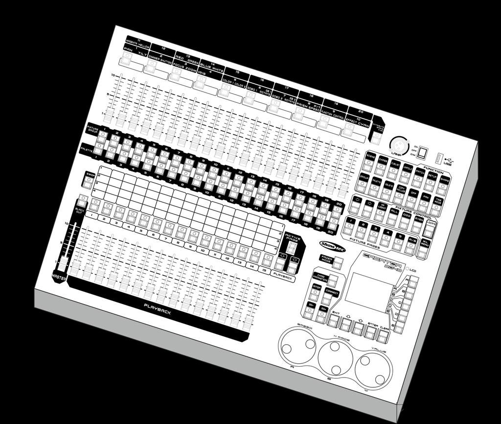
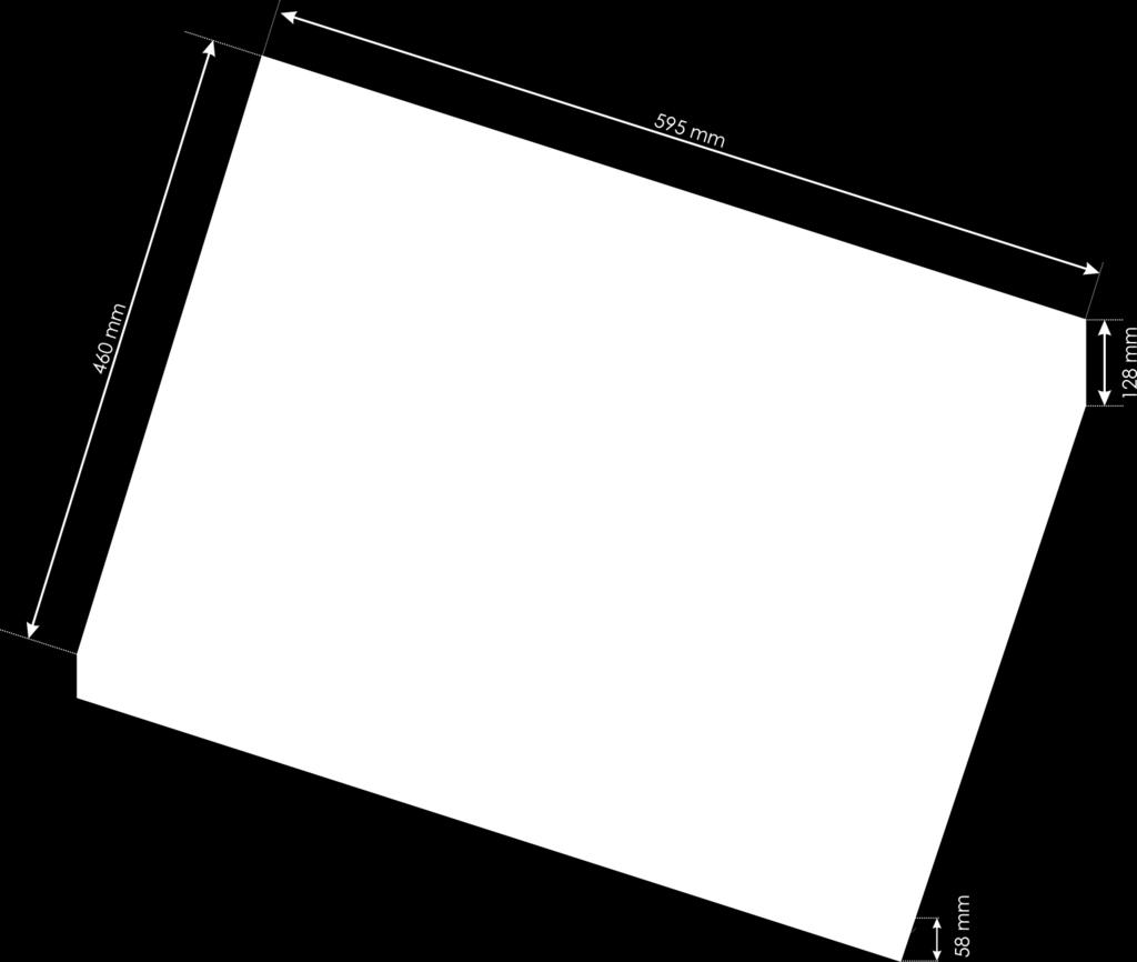
41 Dimensions 40
VGAD-12 ORDERCODE
 VGAD-12 ORDERCODE 101220 Congratulations! You have bought a great, innovative product from DMT. The DMT Media Spinner brings excitement to any venue. Whether you want simple plug-&-play action or a sophisticated
ENGLISH Scanmaster 2 MKII
 MANUAL ENGLISH Scanmaster 2 MKII V1 Highlite International B.V. Vestastraat 2 6468 EX Kerkrade the Netherlands Table of contents Warning...2 Safety Instructions...2 Operating Determinations...3 Connection
LED Pixel Track V3 ORDERCODE 42200
 LED Pixel Track V3 ORDERCODE 42200 Congratulations! You have bought a great, innovative product from Showtec. The Showtec LED Pixel Track brings excitement to any venue. Whether you want simple plug-&-play
Showdesigner 1024 ORDERCODE 50720
 Showdesigner 1024 ORDERCODE 50720 Congratulations! You have bought a great, innovative product from Showtec. The Showtec Showdesigner 1024 brings excitement to any venue. Whether you want simple plug-&-play
ENGLISH Antenna Distributor
 MANUAL ENGLISH Antenna Distributor V1 Highlite International B.V. Vestastraat 2 6468 EX Kerkrade the Netherlands Table of contents Warning... 2 Safety Instructions... 2 Operating Determinations... 4 Connection
SM-8/2 ORDERCODE 50700
 SM-8/2 ORDERCODE 50700 Congratulations! You have bought a great, innovative product from Showtec. The Showtec SM-8/2 brings excitement to any venue. Whether you want simple plug-&-play action or a sophisticated
MANUAL ENGLISH Showmaster 48 MKII V1 Ordercode: 50831
 MANUAL ENGLISH Showmaster 48 MKII V1 Highlite International B.V. Vestastraat 2 6468 EX Kerkrade the Netherlands Table of contents Warning... 2 Safety Instructions... 2 Operating Determinations... 3 Connection
LED Par 56 Short Eco V2 ORDERCODE 42417
 LED Par 56 Short Eco V2 ORDERCODE 42417 Congratulations! You have bought a great, innovative product from Showtec. The Showtec LED Par 56 brings excitement to any venue. Whether you want simple plug-&-play
LED Floodlight 6x 1W, 40 ORDERCODE ORDERCODE ORDERCODE ORDERCODE ORDERCODE ORDERCODE 42760
 LED Floodlight 6x 1W, 40 ORDERCODE 42755 ORDERCODE 42756 ORDERCODE 42757 ORDERCODE 42758 ORDERCODE 42759 ORDERCODE 42760 Congratulations! You have bought a great, innovative product from Showtec. The Showtec
ENGLISH LED Operator 6
 MANUAL ENGLISH V2 Highlite International B.V. Vestastraat 2 6468 EX Kerkrade the Netherlands Table of contents Warning... 2 Unpacking Instructions... 2 Safety Instructions... 2 Operating Determinations...
Professional RGB LED DMX Controller
 Professional RGB LED DMX Controller LC-8PRO Order No. 38.0010 INSTRUCTION MANUAL ELECTRONICS FOR SPECIALISTS ELECTRONICS FOR SPECIALISTS ELECTRONICS FOR SPECIALISTS ELECTRONICS FOR SPECIALISTS Warning...
ENGLISH Optic Fiber Double
 MANUAL ENGLISH Double V1 Highlite International B.V. Vestastraat 2 6468 EX Kerkrade the Netherlands Table of contents Warning... 2 Safety Instructions... 2 Operating Determinations... 4 Rigging... 4 Connection
Commander 384. w w w. p r o l i g h t. c o. u k U S E R M A N U A L
 Commander 384 w w w. p r o l i g h t. c o. u k U S E R M A N U A L 1, Before you begin 1.1: Safety warnings...2 3 1.2: What is included...4 1.3: Unpacking instructions...4 2, Introduction 2.1: Features...4
K-112 ORDERCODE D3551
 K-112 ORDERCODE D31 Congratulations! You have bought a great, innovative product from DAP Audio. The DAP Audio K-112 brings excitement to any venue. Whether you want simple plug-&-play action or a sophisticated
LED Gobo Projector 25W ORDERCODE 40711
 LED Gobo Projector 25W ORDERCODE 40711 Highlite International B.V. Vestastraat 2 6468 EX Kerkrade The Netherlands Phone: +31 45-5667700 Congratulations! You have bought a great, innovative product from
MANUAL ENGLISH Core Club Ordercode: D2314
 MANUAL ENGLISH Core Club Ordercode: Highlite International B.V. Vestastraat 2 6468 EX Kerkrade the Netherlands Table of contents Warning... 2 Unpacking Instructions... 2 Safety Instructions... 2 Operating
LED Spere Direct Control 30 ORDERCODE 41125
 LED Spere Direct Control 30 ORDERCODE 41125 Congratulations! You have bought a great, innovative product from Showtec. The Showtec LED Sphere Direct Control 30 brings excitement to any venue. Whether you
IM-53 Installation Mixer ORDERCODE D2178
 IM-53 Installation Mixer ORDERCODE D2178 Congratulations! You have bought a great, innovative product from DAP Audio. The DAP Audio IM-53 brings excitement to any venue. Whether you want simple plug-&-play
LED Par 56 Short Eco V2 ORDERCODE 42417
 LED Par 56 Short Eco V2 ORDERCODE 42417 Congratulations! You have bought a great, innovative product from Showtec. The Showtec LED Par 56 brings excitement to any venue. Whether you want simple plug-&-play
ENGLISH LED Octostrip Set MKII V1
 MANUAL ENGLISH LED Octostrip Set MKII V1 Highlite International B.V. Vestastraat 2 6468 EX Kerkrade the Netherlands Table of contents Warning... 3 Safety Instructions... 3 Operating Determinations... 5
ENGLISH Dancefloor Sparkle RGB
 MANUAL ENGLISH V1 Highlite International B.V. Vestastraat 2 6468 EX Kerkrade the Netherlands Table of contents Warning... 2 Safety Instructions... 2 Operating Determinations... 4 Connection with the mains...
LED Operator 4 Air ORDERCODE 50726
 LED Operator 4 Air ORDERCODE 50726 Congratulations! You have bought a great, innovative product from Showtec. The Showtec LED Operator 4 Air brings excitement to any venue. Whether you want simple plug-&-play
LED Pixel Track Pro ORDERCODE 42205
 LED Pixel Track Pro ORDERCODE 42205 Congratulations! You have bought a great, innovative product from Showtec. The Showtec LED Pixel Track Pro brings excitement to any venue. Whether you want simple plug-&-play
Pixel Bubble 80 ORDERCODE 41092
 Pixel Bubble 80 ORDERCODE 41092 Highlite International B.V. Vestastraat 2 6468 EX Kerkrade The Netherlands Phone: +31 45-5667700 Congratulations! You have bought a great, innovative product from Showtec.
SC-2412 ORDERCODE 50710
 SC-2412 ORDERCODE 50710 v2 Highlite International B.V. Vestastraat 2 6468 EX Kerkrade The Netherlands Congratulations! You have bought a great, innovative product from Showtec. The Showtec SC2412 brings
Aircone LED 1W ORDERCODE 40313
 Aircone LED 1W ORDERCODE 40313 Highlite International B.V. Vestastraat 2 6468 EX Kerkrade The Netherlands Phone: +31 45-5667700 Congratulations! You have bought a great, innovative product from Showtec.
ENGLISH Helios 200 COB Q4
 MANUAL ENGLISH Helios 200 COB Q4 V3 Highlite International B.V. Vestastraat 2 6468 EX Kerkrade the Netherlands Table of contents Warning... 2 Safety Instructions... 2 Operating Determinations... 4 Rigging...
LED Design Par 18 RGB ORDERCODE 42570
 LED Design Par 18 RGB ORDERCODE 42570 Congratulations! You have bought a great, innovative product from Showtec. The Showtec LED Design Par brings excitement to any venue. Whether you want simple plug-&-play
192 Channel DMX Controller
 DM-X 92 Channel DMX Controller USER MANUAL 54. 9UK Vers ion. D M X 5 2 C O N T R O L L E R S E R I E S Content. Before you begin. What is included.......2 Unpacking instructions....3 Safety instructions...
ENGLISH Odin S-18A Line Array Sub
 MANUAL ENGLISH Odin S-18A Line Array Sub V1 Highlite International B.V. Vestastraat 2 6468 EX Kerkrade the Netherlands Table of contents Warning... 2 Safety Instructions... 2 Connection with the mains...
Show Designer 3. Software Revision 1.15
 Show Designer 3 Software Revision 1.15 OVERVIEW... 1 REAR PANEL CONNECTIONS... 1 TOP PANEL... 2 MENU AND SETUP FUNCTIONS... 3 CHOOSE FIXTURES... 3 PATCH FIXTURES... 3 PATCH CONVENTIONAL DIMMERS... 4 COPY
Ignitor-6 Section Strobe ORDERCODE 40292
 Ignitor-6 Section Strobe ORDERCODE 40292 Highlite International B.V. Vestastraat 2 6468 EX Kerkrade The Netherlands Phone: +31 45-5667700 Congratulations! You have bought a great, innovative product from
Spectra Batten (Order code: LEDJ95)
") www.prolight.co.uk Spectra Batten (Order code: LEDJ95) Safety WARNING FOR YOUR OWN SAFETY, PLEASE READ THIS USER MANUAL CAREFULLY BEFORE YOUR INITIAL START-UP! CAUTION! Keep this equipment away from rain,
www.prolight.co.uk Spectra Batten (Order code: LEDJ95) Safety WARNING FOR YOUR OWN SAFETY, PLEASE READ THIS USER MANUAL CAREFULLY BEFORE YOUR INITIAL START-UP! CAUTION! Keep this equipment away from rain,
TRANSCENSION 6-CHANNEL DMX DIMMER PACK (order code: BOTE40) USER MANUAL
 USER MANUAL") www.prolight.co.uk TRANSCENSION 6-CHANNEL PACK (order code: BOTE40) USER MANUAL SAFETY WARNING FOR YOUR OWN SAFETY, PLEASE READ THIS USER MANUAL CAREFULLY BEFORE YOUR INITIAL START-UP! CAUTION! Keep this
www.prolight.co.uk TRANSCENSION 6-CHANNEL PACK (order code: BOTE40) USER MANUAL SAFETY WARNING FOR YOUR OWN SAFETY, PLEASE READ THIS USER MANUAL CAREFULLY BEFORE YOUR INITIAL START-UP! CAUTION! Keep this
MANUAL. ENGLISH Galaxy 360. Ordercode: Highlite International B.V. Vestastraat EX Kerkrade the Netherlands
 MANUAL ENGLISH Galaxy 360 V1 Highlite International B.V. Vestastraat 2 6468 EX Kerkrade the Netherlands Table of contents Warning... 3 Safety Instructions... 3 Operating Determinations... 5 Rigging...
Studiobeam Tour Q4 4-in-1 LED ORDERCODE 42485
 Studiobeam Tour Q4 4-in-1 LED ORDERCODE 42485 Highlite International B.V. Vestastraat 2 6468 EX Kerkrade The Netherlands Phone: +31 45-5667700 Congratulations! You have bought a great, innovative product
LED Light Bar 8 ORDERCODE 42199
 LED Light Bar 8 ORDERCODE 42199 Congratulations! You have bought a great, innovative product from Showtec. The Showtec LED Light Bar 8 brings excitement to any venue. Whether you want simple plug-&-play
Dragonfly Quad. User Manual V1.4. Order code: EQLED101
 Dragonfly Quad User Manual V1.4 Order code: EQLED101 Safety advice WARNING FOR YOUR OWN SAFETY, PLEASE READ THIS USER MANUAL CAREFULLY BEFORE YOUR INITIAL START-UP! Before your initial start-up, please
ALO 030 MKII. 30 Watt DMX LED scanner. User manual
 ALO 030 MKII 30 Watt DMX LED scanner User manual Safety instructions WARNING! Always keep this device away from moisture and rain! Hazardous electrical shocks may occur! WARNING! Only connect this device
Mini StudioBeam RGB ORDERCODE 42447
 Mini StudioBeam RGB ORDERCODE 42447 Congratulations! You have bought a great, innovative product from Showtec. The Showtec Mini StudioBeam RGB brings excitement to any venue. Whether you want simple plug-&-
MANUAL. ENGLISH NanoQ 19 Q4 IP Ordercode: Highlite International B.V. Vestastraat EX Kerkrade the Netherlands
 MANUAL ENGLISH V1 Highlite International B.V. Vestastraat 2 6468 EX Kerkrade the Netherlands Table of contents Warning... 3 Safety Instructions... 3 Operating Determinations... 5 Rigging... 5 Connection
Concert Series ORDERCODE D3470 ORDERCODE D3471 ORDERCODE D3472 D3470 D3471 D3472
 Concert Series ORDERCODE D3470 ORDERCODE D3471 ORDERCODE D3472 D3470 D3471 D3472 Congratulations! You have bought a great, innovative product from DAP Audio. The DAP Audio Concert Series brings excitement
ENGLISH Pixel Bar 12 MKII
 MANUAL ENGLISH Pixel Bar 12 MKII V1 Highlite International B.V. Vestastraat 2 6468 EX Kerkrade the Netherlands Table of contents Warning... 2 Safety Instructions... 2 Operating Determinations... 4 Rigging...
ENGLISH LED light bar 8
 MANUAL ENGLISH LED light bar 8 V2 Highlite International B.V. Vestastraat 2 6468 EX Kerkrade the Netherlands Table of contents Warning... 2 Safety Instructions... 2 Operating Determinations... 4 Rigging...
American DJ. Show Designer. Software Revision 2.08
 American DJ Show Designer Software Revision 2.08 American DJ 4295 Charter Street Los Angeles, CA 90058 USA E-mail: support@ameriandj.com Web: www.americandj.com OVERVIEW Show Designer is a new lighting
Sessionmix 12 ORDERCODE D2192
 Sessionmix 12 ORDERCODE D2192 Congratulations! You have bought a great, innovative product from DAP Audio. The DAP Audio Sessionmix 12 brings excitement to any venue. Whether you want simple plug-&-play
Mini StudioBeam RGB ORDERCODE 42447
 Mini StudioBeam RGB ORDERCODE 42447 V2 Congratulations! You have bought a great, innovative product from Showtec. The Showtec Mini StudioBeam RGB brings excitement to any venue. Whether you want simple
Cameleon Bar 24-3 ORDERCODE 42695
 Cameleon Bar 24-3 ORDERCODE 42695 Congratulations! You have bought a great, innovative product from Showtec. The Showtec Cameleon Bar 24-3 brings excitement to any venue. Whether you want simple plug-&-play
ENGLISH Spectral M800 Q4 IP65
 MANUAL ENGLISH Spectral M800 Q4 IP65 V1 Highlite International B.V. Vestastraat 2 6468 EX Kerkrade the Netherlands Table of contents Warning... 3 Safety Instructions... 3 Operating Determinations... 5
LED-BANK4 USER MANUAL. COLORbank 4
 LED-BANK4 COLORbank 4 USER MANUAL CHAUVET, 3000 N 29 th Ct, Hollywood, FL 33020 U.S.A (800) 762-084 (954) 929-5 FAX (954) 929-5560 www.chauvetlighting.com 2006-04-8/6:44 Table of Content BEFORE YOU BEGIN...
ORDER CODE: EQLED65 USER MANUAL
 www.prolight.co.uk ORDER CODE: EQLED65 USER MANUAL Safety WARNING FOR YOUR OWN SAFETY, PLEASE READ THIS USER MANUAL CAREFULLY BEFORE YOUR INITIAL START-UP! CAUTION! Keep this equipment away from rain,
Fusion 120 Zoom. User Manual. Order code: EQLED068
 Fusion 120 Zoom User Manual Order code: EQLED068 Safety advice WARNING FOR YOUR OWN SAFETY, PLEASE READ THIS USER MANUAL CAREFULLY BEFORE YOUR INITIAL START-UP! Before your initial start-up, please make
DMX Operator 192-channel lighting controller
 USER MANUAL DMX Operator 192-channel lighting controller CAUTION! Keep this device away from rain and moisture! Unplug mains lead before opening the housing! For your own safety, please read this user
Tracker Q4 ORDERCODE 41388
 Tracker Q4 ORDERCODE 41388 Highlite International B.V. Vestastraat 2 6468 EX Kerkrade The Netherlands Phone: +31 45-5667700 Congratulations! You have bought a great, innovative product from Showtec. The
DMX48. User s instruction manual. 24 Channel DMX controller
 WWW.LIGHTEMOTIONS.COM.AU DMX48 24 Channel DMX controller User s instruction manual This manual contains important information about the safe installation and use of this product Please read this instruction
ENGLISH Spectral M800 MKII
 MANUAL ENGLISH Spectral M800 MKII V1 Highlite International B.V. Vestastraat 2 6468 EX Kerkrade the Netherlands Table of contents Warning... 3 Safety Instructions... 3 Operating Determinations... 5 Rigging...
SHOW DESIGNER 1. user manual. ELATION SHOW DESIGNER 1 user manual
 SHOW DESIGNER 1 user manual ELATION SHOW DESIGNER 1 user manual 2015 ELATION PROFESSIONAL all rights reserved. Information, specifications, diagrams, images, and instructions herein are subject to change
AVOLITES DIAMOND II OPERATION MANUAL SOFTWARE VERSION 3.x
 AVOLITES DIAMOND II OPERATION MANUAL SOFTWARE VERSION 3.x revision 3.01 Useful phone numbers:- Avolites England sales and service (+44) (0) 181 965 8522 service out of hours (+44) (0) 831 17 88 88 fax
OSO 1612 operator. DMX controller. User manual
 OSO 1612 operator DMX controller User manual Safety instructions WARNING! Always keep this device away from moisture and rain! Hazardous electrical shocks may occur! WARNING! Only connect this device to
Phantom 20 LED Beam ORDERCODE 40182
 Phantom 20 LED Beam ORDERCODE 40182 Highlite International B.V. Vestastraat 2 6468 EX Kerkrade The Netherlands Phone: +31 45-5667700 Congratulations! You have bought a great, innovative product from Showtec.
Snapshot. Obey 10 DMX Controller USER MANUAL
 Obey 10 DMX Controller Snapshot Ok on Dimmer Outdoor OK Sound Activated DMX512 Master/Slave 115V/230V Switch Replaceable Fuse User Serviceable Duty Cycle USER MANUAL Chauvet, 3000 N 29 th Ct, Hollywood,
Stratos Duo RGB. User Manual. Order code: EQLED371
 Stratos Duo RGB User Manual Order code: EQLED1 Safety advice WARNING FOR YOUR OWN SAFETY, PLEASE READ THIS USER MANUAL CAREFULLY BEFORE YOUR INITIAL START-UP! Before your initial start-up, please make
2002 Martin Professional A/S, Denmark.
 Freekie user manual 2002 Martin Professional A/S, Denmark. All rights reserved. No part of this manual may be reproduced, in any form or by any means, without permission in writing from Martin Professional
Arc-Bar 3 ORDERCODE 41350
 Arc-Bar 3 ORDERCODE 41350 Congratulations! You have bought a great, innovative product from Showtec. The Showtec Arc-Bar 3 brings excitement to any venue. Whether you want simple plug-&-play action or
LED Thunder S-150 Code 1097
 LED Thunder S-150 Code 1097 User Manual 1 1 SAFETY INSTRUCTIONS This device has left the factory in perfect condition. In order to maintain this condition and to ensure a safe operation, it is absolutely
KONTROL channels DMX controller USER MANUAL. For safety, please read this user manual carefully before initial use.
 KONTROL192 192 channels DMX controller USER MANUAL For safety, please read this user manual carefully before initial use. Event Lighting reserves the right to revise the manual at any time. Information
LED Spot 300W. Please read this user manual before your operation
 LED Spot 300W Please read this user manual before your operation 1. Introduction 2. General Guideline 3. Safety Instructions 4. Cleaning and Maintenance 5. Technical Parameters 6. DMX Channels 7. Remark
DMX-7 USER MANUAL. Universal DMX Controller
 DMX-7 Universal DMX Controller USER MANUAL Chauvet, 3000 N 29 th Ct, Hollywood, FL 33020 U.S.A (800) 762-1084 (954) 929-1115 FAX (954) 929-5560 www.chauvetlighting.com 2006-03-20/15:55 TABLE OF CONTENT
Phantom 140 LED Beam ORDERCODE 40194
 Phantom 140 LED Beam ORDERCODE 40194 Highlite International B.V. Vestastraat 2 6468 EX Kerkrade The Netherlands Phone: +31 45-5667700 Congratulations! You have bought a great, innovative product from Showtec.
THE FROG SERIES OPERATING MANUAL
 THE FROG SERIES OPERATING MANUAL THE FROG SERIES OPERATING MANUAL If a portable or temporary three phase mains supply is used to power this desk, we recommend that the desk mains plug is removed before
LED-PAR200B USER MANUAL. COLORsplash 200B
 LED-PAR00B COLORsplash 00B USER MANUAL CHAUVET, 3000 N 9 th Ct, Hollywood, FL 3300 U.S.A (800) 76-084 (954) 99-5 FAX (954) 99-5560 www.chauvetlighting.com 006-07-06/0:3 TABLE OF CONTENT TABLE OF CONTENT...
DMX192S Controller INSTRUCTION MANUAL. Ref. nr.: V2.1
 DMX192S Controller Ref. nr.: 154.060 INSTRUCTION MANUAL V2.1 2 ENGLISH Congratulations to the purchase of this Beamz product. Please read this manual thoroughly prior to using the product in order to benefit
COLORtube EQ Controller
 COLORtube EQ LED-EQ COLORtube EQ Controller LED-EQC USER MANUAL 32-band audio spectrum visualizer using LED tubes CHAUVET, 3000 N 29 th Ct, Hollywood, FL 33020 U.S.A (800) 762-1084 (954) 929-1115 FAX (954)
Oxygen ORDERCODE D2150
 Oxygen ORDERCODE D2150 Congratulations! You have bought a great, innovative product from DAP Audio. The DAP Audio Oxygen brings excitement to any venue. Whether you want simple plug-&-play action or a
OPERATING MANUAL. including
 OPERATING MANUAL including & If a portable or temporary three phase mains supply is used to power this desk, we recommend that the desk mains plug is removed before connecting or disconnecting the supply.
TABLE OF CONTENTS. Rev. 9 2 Stage Designer 50
 User Manual TABLE OF CONTENTS Table of Contents... 2 WHAT IS INCLUDED... 3 UNPACKING INSTRUCTIONS... 3 MANUAL CONVENTIONS... 3 ICONS... 3 SAFETY INSTRUCTIONS... 4 FEATURES... 4 ADDITIONAL FEATURES... 4
Colour Control48 Order Code: Control48
 Colour Control48 Order Code: Control48 www.cobrainternational.com User Manual Cobra Colour Control 48 Dear Customer, Thank you for purchasing the Cobra Colour Control 48. With decades of experience in
Owner s Manual LED COMMANDER 16/2
 Owner s Manual LED COMMANDER 16/2 Content Introduction...2 Technical Specification...2 Maintenance and care...2 Notes on safety...3 Features...4 Overview...5 Installation...6 Operation...6 Channel Assignment...7
BEAM MOVING HEAD YODN Lamp. 132W 2R MOVING HEAD Brightness / Stability USER MANUAL. Version 1.0 beta
 BEAM MOVING HEAD YODN Lamp W R MOVING HEAD Brightness / Stability This product manual contains important information about the safe installation and use of this projector. Please read and follow these
Controller DMX DC-1224
 Manual Controller DMX DC-1224 Table of Contents 1. Safety instructions... 4 1.1. FOR SAFE AND EFFICIENT OPERATION... 4 3. Overview... 6 3.1. Front view... 6 3.2. Rear view... 9 4. Operation guide... 10
DMX OPERATOR PRO. User Manual
 User Manual (24-004-1262 Rev 2.0) E-mail: support@elationlighting.com Internet: http://www.elationlighting.com Sections: Table of Contents DMX OPERATOR PRO 1 : General Introduction..... 3 2 : Safety Information
STAGE SETTER-8. User Instructions. Elation Professional 4295 Charter Street Los Angeles Ca
 Introduction STAGE SETTER-8 User Instructions Introduction: Thank you for purchasing the Elation Professional Stage Setter 8. To optimize the performance of this product, please read these operating instructions
User Manual. 360W LED Moving Zoom KEEP THIS MANUAL FOR FUTURE NEEDS. 36pcs10W 4 in 1 RGBW LEDs
 User Manual 360W LED Moving Zoom 36pcs10W 4 in 1 RGBW LEDs KEEP THIS MANUAL FOR FUTURE NEEDS 1. Dispacking Thank you for choosing our moving head. For your own safety, please read this manual before installing
LED Beam Moving Head. TWIST-150LED Order No INSTRUCTION MANUAL
 LED Beam Moving Head TWIST-150LED Order No. 38.7970 INSTRUCTION MANUAL MONACOR INTERNATIONAL GmbH & Co. KG Zum Falsch 36 28307 Bremen Germany www.monacor.com 01.30.11.2016 ELECTRONICS FOR SPECIALISTS ELECTRONICS
USER MANUAL. TS-3 DMX-Scanner. For your own safety, please read this user manual carefully before you initial start-up.
 USER MANUAL TS- DMX-Scanner For your own safety, please read this user manual carefully before you initial start-up. Every person involved with the installation, operation and maintenance of this device
KingWash 7QX 7x40w,Zoom 5-60degree. User manual. Please read the instructions carefully before use TABLE OF CONTENTS
 KingWash 7QX 7x40w,Zoom 5-60degree User manual Please read the instructions carefully before use TABLE OF CONTENTS 1. Safety Instructions... 2 2. Technical Specifications... 4 3. How To Control The Unit...
USER MANUAL Table of Contents
 USER MANUAL Table of Contents Safety Information. 3 Specifications.. 4 Main Power Connection.. 5 DMX-512 Connection...... 5 Main Control Menu... 6 Fixture Addressing... 6 Manual Mode...7 Save Scene...7
USER MANUAL. DE-1 Police-light. CAUTION! Keep this device away from rain and moisture! Unplug mains lead before opening the housing!
 USER MANUAL DE-1 Police-light CAUTION! Keep this device away from rain and moisture! Unplug mains lead before opening the housing! For your own safety, please read this user manual carefully before you
ArtFox Lighting. LED Beam Wash 19E. User manual. 6. Fixture Cleaning. Please read the instructions carefully before use
 6. Fixture Cleaning ArtFox Lighting LED Beam Wash 19E The cleaning of internal and external optical lenses and/or mirrors must be carried out periodically to optimize light output. Cleaning frequency depends
TABLE OF CONTENTS. 2 SGM Light Technology 23/08/1999 Ver. 2.00
 Version 2.0 TABLE OF CONTENTS 2 SGM Light Technology 23/08/1999 Ver. 2.00 STUDIO SC USER GUIDE To Clear All the Memory...5 Manual Preset Section...6 The single or double preset:...7 To set the Single or
RD RACK MOUNT DIMMER OWNERS MANUAL VERSION /09/2011
 RD - 122 RACK MOUNT DIMMER OWNERS MANUAL VERSION 1.3 03/09/2011 Page 2 of 14 TABLE OF CONTENTS UNIT DESCRIPTION AND FUNCTIONS 3 POWER REQUIREMENTS 3 INSTALLATION 3 PLACEMENT 3 POWER CONNECTIONS 3 OUTPUT
Led Dynamic DMX Tri Curtain Manual
 Led Dynamic DMX Tri Curtain Manual Welcome to use the LED dynamic DMX Tri curtain, please read following Safety Notes as well as those in User Manual carefully before connection, installing, operation
1. BEFORE YOU BEGIN INTRODUCTION CONTROL FEATURES... 5 Additional Features... 5 PRODUCT OVERVIEW SETUP... 6
 User Manual TABLE OF CONTENTS 1. BEFORE YOU BEGIN... 3 WHAT IS INCLUDED... 3 UNPACKING INSTRUCTIONS... 3 MANUAL CONVENTIONS... 3 ICONS... 3 SAFETY INSTRUCTIONS... 4 2. INTRODUCTION... 5 CONTROL FEATURES...
ALO 060 DMX LED scanner
 ALO 060 DMX LED scanner User manual Safety instructions WARNING! Always keep this device away from moisture and rain! Hazardous electrical shocks may occur! WARNING! Only connect this device to a matching
USER'S MANUAL. ADJ R Junostraat EW Kerkrade
 USER'S MANUAL ADJ R Junostraat EW Kerkrade www.adj.com Improvement and changes to specifications, design and this manual, may be made at any time without prior notice. All Rights Reserved Contents Features
USER GUIDE 8-CHANNEL DMX CONTROLLER December 2013 Version 1.0 CHASE / STROBE SPEED FADE SPEED RED GREEN BLUE WHITE AMBER DIMMER INSERT
 8-CHANNEL DMX CONTROLLER RED GREEN BLUE YELLOW 1 2 3 4 5 6 CYAN ORANGE PURPLE WHITE RED GREEN BLUE WHITE AMBER DIMMER RECORD INSERT DELETE TAP CLEAR MANUAL MUSIC 1 2 3 5 6 7 AUTO CHASE / STROBE SPEED 4
CR-6 MIXER USER MANUAL ENGLISH. Order Code: MIXE01
 CR-6 MIXER P R O F E S S I O N A L 1 9 R A C K M I X E R Order Code: MIXE01 w w w. p r o l i g h t. c o. u k USER MANUAL ENGLISH WARNING FOR YOUR OWN SAFETY, PLEASE READ THIS USER MANUAL CAREFULLY BEFORE
TL5024 MEMORY LIGHTING CONSOLE OWNERS MANUAL. Version 1.01
 TL5024 MEMORY LIGHTING CONSOLE OWNERS MANUAL Version 1.01 09/22/2017 Page 2 of 14 SPECIFICATIONS Total channels Operating modes Scene memory Chase 12 or 24 depending on mode 12 channels x 2 manual scenes
Fixture One XLR Signal Cable One Omega Clamp - Two Safety Chain One User Manual - One
 TABLE OF CONTENTS 1. INTRODUCTION AND UNPACKING 1 2. SAFTEY INSTRUCTIONS 1-2 3. OPERATION INSTRUCTIONS 2-3 4. MOUNTING AND INSTALLATION 3-4 5. DMX-512 CONTROL CONNECTIONS 4-5 6. MENU NAVIGATION 5 7. PHOTOMETRIC
Infinity is-200 ORDERCODE 41501
 Infinity is-200 ORDERCODE 41501 Highlite International B.V. Vestastraat 2 6468 EX Kerkrade The Netherlands Phone: +31 45-5667700 Congratulations! You have bought a great, innovative product from Showtec.