Congratulations on your purchase of the SIR-ECL1 the ECLIPSE Compatible SIRIUS Satellite Radio Tuner!
|
|
|
- Rebecca Rice
- 6 years ago
- Views:
Transcription
1 Installation Guide
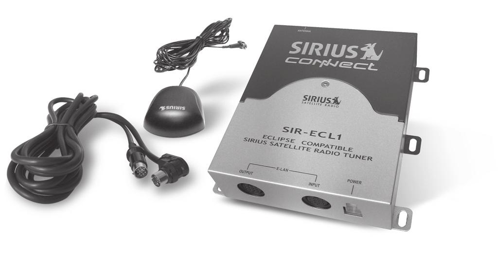
2 Congratulations on your purchase of the SIR-ECL1 the ECLIPSE Compatible SIRIUS Satellite Radio Tuner! Your new SIRIUS Tuner is designed to work with 2005 and up ECLIPSE E-LAN headunits that are designated SIRIUS READY. Contact ECLIPSE or SIRIUS for model compatibility. What is SIRIUS Satellite Radio? Over 120 channels of the best entertainment and completely commercial-free music for your car, home or office. Only SIRIUS has more than 65 original music channels, from today s hits to R&B oldies to classical masterpieces. From authentic country and real bluegrass to cool jazz, hot latin, reggae, rock and many more. Best of all, it s all completely commercial-free. SIRIUS also has more than 55 channels of world-class sports, news and entertainment. Included as part of your subscription, you get up to 16 NFL games a week, up to 40 NBA games a week and up to 40 NHL games a week. (Games are broadcasted during their respective seasons.) Coupled with great sports news from ESPN, the SIRIUS sports offering is unrivaled. And don t forget a host of other great news and entertainment, like NPR, CNBC, Fox News, Radio Disney and E! Entertainment Radio. With SIRIUS, the emphasis is on the music and entertainment you want. The music is hosted by SIRIUS Jockeys, who are true experts. They back-up the music with compelling information about the song being played, and they understand that sometimes it s best to just let the music speak for itself. Rely on SIRIUS rocket science for superior coverage. Only SIRIUS has three powerful satellites that fly directly over the U.S. ensuring coast-to-coast coverage with high elevation angles. This gives the satellites a clear line of sight to your car or home, with much less concern for buildings, trees or other objects that might block conventional satellite signals. Once you experience more than 120 channels of digital entertainment, you ll never want to leave your car. For more information, visit 2 SIR-ECL1 Installation Guide
3 Table of Contents Package Contents... 3 Warnings and Cautions... 4 Installation... 6 Mounting the Tuner... 6 Installing the Antenna... 6 Optimum Antenna Mounting Locations... 7 Wiring and Cable Connections... 8 System Connection Examples Activating Your SIRIUS Subscription Basic Opperation SIRIUS Compatibity Features Headunit Messages Specifications Warranty Package Contents A B C D E A SIR-ECL1 Tuner F B Magnetic Micro Antenna C Antenna Cable Cover/Tail D Alcohol Swab E Power Harness With In-Line Filter/Fuse F 3.5-Meter E-LAN Cable G 6 Mounting Screws G SIR-ECL1 Installation Operation and Guide Installation Guide 3
4 WARNING This symbol means important instructions. Failure to heed them can result in serious injury or death. DO NOT OPERATE ANY FUNCTION THAT TAKES YOUR ATTENTION AWAY FROM SAFELY DRIVING YOUR VEHICLE. Any function that requires your prolonged attention should only be performed after coming to a complete stop. Always stop the vehicle in a safe location before performing these functions. Failure to do so may result in an accident. DO NOT OPEN, DISASSEMBLE OR ALTER THE UNIT IN ANY WAY. Doing so may result in fire, electric shock or product damage. DO NOT INSERT ANY OBJECTS INTO THE UNIT. Doing so may result in fire, electric shock or product damage. USE THE CORRECT AMPERE RATING WHEN REPLACING FUSE. Failure to do so may result in fire, electric shock or product damage. MAKE THE CORRECT CONNECTIONS. Failure to make proper connections may result in fire or product damage. DO NOT SPLICE INTO A ELECTRICAL CABLES. Never cut away cable insulation to supply power to other equipment. Doing so will exceed the current carrying capacity of the wire and result in fire or electric shock. DO NOT INSTALL IN LOCATIONS THAT MIGHT HINDER VEHICLE OPERATION. Doing so may obstruct vision or hamper movement which can result in a serious accident. DO NOT INSTALL THE UNIT WHERE IT WILL BE EXPOSED TO HIGH LEVELS OF HUMIDITY, MOISTURE OR DUST. Doing so can result in electric shock or product failure. FCC Warning: This equipment may generate or use radio frequency energy. Changes or modifications to this equipment may cause harmful interference unless the modifications are expressly approved in this User Guide. The user could lose the authority to operate this equipment if an unauthorized change or modification is made. Note: This equipment has been tested and found to comply with Part 15 of the FCC Rules. These rules are designed to provide reasonable protection against harmful interference. This equipment may cause harmful interference to radio communications if it is not installed and used in accordance with these instructions. However, there is no guarantee that interference will not occur in a particular installation. If this equipment does cause harmful interference to radio or television reception, which can be determined by turning the equipment off and on, the user is encouraged to try to correct the interference by one of more of the following measures: Relocate the receiving antenna. Consult the dealer or an experienced technician for help. 4 SIR-ECL1 Installation Guide
5 CAUTION This symbol means important instructions. Failure to heed them can result in injury or material property damage. HALT USE IMMEDIATELY IF A PROBLEM APPEARS. Failure to do so may cause personal injury or damage to the product. Return the unit to your authorized retailer or nearest service center for repairing. INSTALL THE WIRING SO THAT IT IS NOT CRIMPED OR PINCHED BY SCREWS OR SHARP METAL EDGES. Route the cables away from moving parts or sharp pointed edges. This will prevent crimping and damage to the wiring. If the wiring must pass through a metal hole, be sure to use a rubber grommet to prevent the wire s insulation from being cut by the metal edge of the hole. USE THE SPECIFIED ACCESSORY PARTS AND INSTALL THE PRODUCT SECURELY. Be sure to use only the specified accessory parts. Use of nonspecified parts may damage this unit internally or may not securely install the unit in place. This may cause parts to become loose, resulting in hazards or product failure. USE CAUTION IF YOU NEED TO DISCONNECT THE BATTERY TERMINAL. Please consult the vehicle s owner s manual or a service technician prior to removing the battery positive or ground connection, as it may cause damage to the vehicle s electrical system or require reprogramming of the vehicle s computer-controlled devices. SIR-ECL1 Installation Operation and Guide Installation Guide 5
6 Installation It is recommended that prior to starting the installation, you thoroughly read this manual and follow the guidelines listed below: Consider the mounting location carefully. You should make sure that you avoid the following: Any location where the tuner is exposed to moisture. Any location where the unit is exposed to extreme heat. Any location that would interfere with moving parts on the vehicle or hamper driving. Mounting the SIR-ECL1 Tuner Be sure that you find a location that is flat and has clearance above the unit to prevent any damage as well as allow for ventilation. Do not install the tuner under the carpet or in a small enclosed area without proper ventilation. Doing so can result in damage to the tuner or the vehicle. Use the supplied screws to securely fasten the unit. Caution: If you are attaching the unit directly to the vehicle s chassis, be sure that you check to make sure the area behind the unit is free from moving parts, fuel or break lines, wire harnesses or any other items which may get damaged by drilling a mounting hole or using the supplied screws. Installing the Antenna The antenna includes a 6-1/2 cable cover/tail which covers the exposed antenna cable and keeps it attached securely to vehicle roof. The tail also helps position the antenna the proper distance from the window, sunroof or rear hatch. To attach the cover/tail: 1) Once you have determined the proper mounting location (see next section), clean the area with the supplied alcohol swab 3) Connect the cover/tail to the antenna cable, making sure that the strainrelief on the antenna seats into the cover/tail groove. Route the cable through the wire channel in the cover/tail. Antenna (Bottom) Adhesive Strips Cable Cover/Tail 6 SIR-ECL1 Installation Guide
7 4) Remove the protective tape from the adhesive, carefully position the antenna with cover/tail and apply pressure to secure to the vehicle. Cable Cover/Tail Antenna For SUVs, minivans and five-door vehicles, bring the cable into the vehicle under the rubber molding for the tailgate, and continue under the interior trim. From the trunk, carefully route the cable to the location of the SIR-ECL1 and plug the SMB connector onto the unit. Sedan/Coupe Vehicle Optimum Antenna Mounting Locations The optimum location to mount the SUV/Mini-Van included antenna is on the roof of the vehicle. It is important to avoid any obstruction that will block satellite signal like a roof rack. For convertible vehicles, install the antenna on the trunk lid. Truck Place the antenna on a metal surface of your vehicle at least 12" x 12", and at least 6" from a window. (Use the antenna cover/tail as a guide for the proper distance). Convertible (only) The antenna s powerful magnet will secure it to the metal surface. The adhesive that is attached to the antenna cover/tail will secure the cable to the vehicle. Before routing the antenna cable, confirm that the antenna is mounted in a good Caution: location. Do not pull the wire across sharp Route the cable from the antenna to edges that could damage it. the vehicle s interior by tucking it Keep the wire away from areas underneath the rubber molding where it could become tangled in around the rear window (if possible). the driver s and passenger s feet. Route the cable from the lowest point Keep the antenna wire away from of the rear window into the trunk. extreme heat like exhaust systems. Take advantage of any existing cable Avoid placing the cable near any channels or wiring conduits. moving parts. SIR-ECL1 Installation Operation and Guide Installation Guide 7
8 Wiring and Cable Connections A Antenna Input Connect the right-angle SMB connector from the antenna. Push firmly to attach. E-LAN Output Connector Use the supplied E-LAN cable to connect to the ECLIPSE Headunit See System Connection Examples for more specific details. E-LAN Input Connector Connect to optional ECLIPSE audio equipment like CD Changers - See System Connection Examples for more specific details. B C D Power Harness Connector After the wiring connections are complete, plug the wiring harness into the connector. Make sure to insert firmly to lock the connector in place. 1 2 A B C D Antenna Input (SMB) E-LAN Output Connector E-LAN Input Connector Power Connector Open Battery (+) Chassis Ground ( ) 4 Open 8 SIR-ECL1 Installation Guide
9 Right-angle SMB Connector Antenna (21 cable) - Mount on Roof of Vehicle Power Harness Yellow Connect to Battery Positive 1AMP Fuse Black Connect to Chassis Ground To access the fuse, remove the top cover of the in-line filter/fuse box Power Harness Connector After the wiring connections are complete, plug the wiring harness into the connector. Make sure to insert firmly to lock the connector in place. *NOTE* BE SURE TO CONNECT THE BATTERY (Yellow) AND GROUND (Black) WIRES CORRECTLY. IF THEY ARE CROSSED, THE FUSE INSTALLED IN THE POWER HARNESS FUSE BOX WILL BLOW. 3.5-meter E-LAN Cable (Connect to ECLIPSE Sirius-Ready Headunit) SIR-ECL1 Installation Operation and Guide Installation Guide 9
10 System Connection Examples System 1: ECLIPSE Headunit and SIR-ECL1 Eclipse Sirius-Ready Headunit (E-LAN CD Player or AVN system) System 2: ECLIPSE Headunit, CD Changer and SIR-ECL1 Eclipse Sirius-Ready Headunit (E-LAN CD Player or AVN system) Optional Eclipse CD Changer (CH3083) CD Changer (TOP) H L Note: Set to L for Primary CD Changer 10 SIR-ECL1 Installation Guide
11 System Connection Examples System 3: ECLIPSE Headunit, 2 CD Changers and SIR-ECL1 Eclipse Sirius-Ready Headunit (E-LAN CD Player or AVN system) Optional Eclipse CD Changers (CH3083) x 2 CD Changer 1 (TOP) H L Note: Set to L for Primary CD Changer CD Changer 2 (TOP) H L Note: Set to H for Secondary CD Changer SIR-ECL1 Installation Operation and Guide Installation Guide 11
12 Activating Your SIRIUS Subscription You must activate SIR-ECL1 before you can start to receive the SIRIUS Satellite Radio broadcast. 1. Make sure that the SIR-ECL1 is properly connected and that its antenna is oriented to receive the SIRIUS satellite signal. 2. Turn on the ECLIPSE headunit. 3. Select SIRIUS as the source: CD Headunits: Press and Hold the FM/AM button to select SIRIUS as the source. AVN Headunits: Press the SIRIUS button (located on the touch screen) to select SIRIUS as the source. NOTE: If this is the first time selecting SIRIUS as a source, the display may show the text UPDATING - which means the SIR-ECL1 is receiving important channel or category updates. NOTE: Don t push any buttons or perform any operations until updating has been completed. Once updated and the SIRIUS channels are received, the display will change to Channel 184 the SIRIUS Satellite Radio s Preview Channel (the display will show CH184 and CALL SIRIUS ). At this time you should also be able to hear the audio from the Preview Channel. 4. To display the SIRIUS ID: For CD Headunits: Each time you Press and hold (some units Press and Release) the DISP button the display content will change- repeat until the SIRIUS ID appears on the display. For AV Headunits: Some AVN units will display the SID on the top of the display at all times when in the SIRIUS source mode. All others you must Press INFO button on the face of the unit, then press the SIRIUS button (located on the touch screen). The SIRIUS ID will display on the screen. 5. The SIRIUS ID is a 12-digit number. Write down the SIRIUS ID (SID) in the location provided on the next page for future reference. Note: If the SIRIUS-ID does not show up on the text display of the headunit, the SIR-ECL1 has been deactivated. To obtain the SIRIUS- ID, you must get it from the unit itself. The SIRIUS-ID can also be found on the sticker that is on the bottom of the SIR-ECL1 as well as on the original packaging. 6. Contact SIRIUS on the Internet: Follow the instructions to activate your subscription. You can also call SIRIUS toll-free at SIRIUS ( ) to activate your service. Note: You will not be able to tune to any other channels until you activate your SIRIUS subscription. 7. When the subscription is activated or updated, the word SUB UPDATED will appear on the display. Note some ECLIPSE headunits will have different messages- please consult your headunit owners manual for more information. 8. Once the SUB UPDATED text message disappears, you may now tune to any actively subscribed channel. 12 SIR-ECL1 Installation Guide
13 Basic Operation The SIR-ECL1 SIRIUS Satellite Radio Tuner is compatible with any ECLIPSE headunit that is Sirius- Ready which includes most 2005 models. Consult ECLIPSE or Sirius Customer Support Departments for more information about compatibility. Please consult your ECLIPSE owner s manual for proper operation instructions for using satellite radio products. SIRIUS Compatible Features The following features are compatible with 2005 Eclipse Headunits: Channel Tune UP/DN Category Tune - UP/DN Channel tune within a Category - UP/DN Diriect Channel Selection Preset Memory - 6 Presets per Band, 4 Bands (24 total) Preset Channel Scan Text Display Information*: Channel Number Channel Name Category Song Title Artist SIRIUS-ID** * Note that any Special Characters (&,@, %, etc.) that are sent to the system may show up as blank spaces or as asterisk symbolsthis is a limitation of the headunit. Also note that Eclipse headunits do not support the Composer information field ** Note that the SIRIUS ID (SID) can only be viewed while tuned to any valid subscribed channel. If the unit has been deactivated, ALL CHANNELS become unsubscribed. Obtain the SID from the bottom of the SIR-ECL1 Headunit Messages These messages vary by headunit model- consult your ECLIPSE owners manual for more information. UPDATING - Indicates that the SIR- ECL1 is receiveing a channel or category update. SUB UPDATED - This message appears when the SIR-ECL1 is receiving a subscription update. ACQUIRING - Will display when there is weak or no antenna signal present. INVALID - Will display when tuned to an invalid channel. ANTENNA - Will display if the antenna is damaged or disconnected. CALL SIRIUS - Will display on an unsubscribed channel. SIR-ECL1 Installation Operation and Guide Installation Guide 13
14 Specifications Operational Frequencies Satellite / MHz Terrestrial MHz Power Requirements Volts DC Fuse Type... 1-AMP (Glass) Chassis Size (without Mounting Tabs) /8 x 5 x 1-3/8 (W XHXD) mm x 126mm x 35mm (WxHxD) Chassis Size (with Mounting Tabs) /8 x 5 x 1-3/8 (W XHXD) mm x 126mm x 35mm (WxHxD) Antenna Type... Mini-Magnetic Antenna Cable Length (single micro-cable) Connector Type... SMB (Right-angle) Audio Interface... 2 E-LAN Connectors (Input/Output) Audio Output mV (Fixed) Included Cable Meter E-LAN (Male/Male) Please write down your SIRIUS-ID in the space provided below: SIRIUS ID: SIRIUS Customer Service: Note: Design and specifications are subject to change without notice. 14 SIR-ECL1 Installation Guide
15 12 MONTH LIMITED WARRANTY Sirius Satellite Radio warrants to the original retail purchaser of this product that should this product or any part thereof, under normal use and conditions, be proven defective in material or workmanship within 12 months from the date of original purchase, such defect(s) will be repaired or replaced with new or reconditioned product (at the Company s option) without charge for parts and repair labor. To obtain repair or replacement within the terms of this Warranty, the product is to be delivered with proof of warranty coverage (e.g. dated bill of sale), specification of defect(s), transportation prepaid, to the location shown below under WARRANTY RETURN. This Warranty does not extend to the elimination of externally generated static or noise, to correction of antenna problems, to costs incurred for installation, removal or reinstallation of the product, or to damage to tapes, compact discs, speakers, accessories, or vehicle electrical systems. This Warranty does not apply to any product or part thereof which, in the opinion of the Company, has suffered or been damaged through alteration, improper installation, mishandling, misuse, neglect, accident, or by removal or defacement of the factory serial number/bar code label(s). THE EXTENT OF THE COMPANY S LIABILITY UNDER THIS WARRANTY IS LIMITED TO THE REPAIR OR REPLACEMENT PROVIDED ABOVE AND, IN NO EVENT, SHALL THE COMPANY S LIABILITY EXCEED THE PURCHASE PRICE PAID BY PURCHASER FOR THE PRODUCT. This Warranty is in lieu of all other express warranties or liabilities. ANY IMPLIED WARRANTIES, INCLUDING ANY IMPLIED WARRANTY OF MERCHANTABILITY, SHALL BE LIMITED TO THE DURATION OF THIS WRITTEN WARRANTY. ANY ACTION FOR BREACH OF ANY WARRANTY HEREUNDER INCLUDING ANY IMPLIED WARRANTY OF MERCHANTABILITY MUST BE BROUGHT WITHIN A PERIOD OF 48 MONTHS FROM DATE OF ORIGINAL PURCHASE. IN NO CASE SHALL THE COMPANY BE LIABLE FOR ANY CONSEQUENTIAL OR INCIDENTAL DAMAGES FOR BREACH OF THIS OR ANY OTHER WARRANTY, EXPRESS OR IMPLIED, WHATSOEVER. No person or representative is authorized to assume for the Company any liability other than expressed herein in connection with the sale of this product. Some states do not allow limitations on how long an implied warranty lasts or the exclusion or limitation of incidental or consequential damage so the above limitations or exclusions may not apply to you. This Warranty gives you specific legal rights and you may also have other rights which vary from state to state. WARRANTY RETURN: To obtain repair or replacement within the terms of this Warranty, please return product to an authorized ECLIPSE Dealer or call (800) Proof of purchase and description of defect are required. Products to be returned to an approved warranty station must be shipped freight prepaid. SIR-ECL1 Installation Operation and Guide Installation Guide 15
16 SIRIUS Satellite Radio 1221 Avenue of the Americas New York, NY (888) Distributed by ECLIPSE Contact: Fujitsu Ten Corp. of America South Vermont Ave. Torrance, CA (800) SIRIUS Satellite Radio Inc. SIR-ECL1 Manual (Feb Rev. A)
SIR-GM1 GM CLASS-2 BUS COMPATIBLE SIRIUS SATELLITE RADIO TUNER
 SIR-GM1 GM CLASS-2 BUS COMPATIBLE SIRIUS SATELLITE RADIO TUNER Installation Guide Congratulations on your purchase of the SIR-GM1 the GM Compatible SIRIUS Satellite Radio Tuner! Your SIR-GM1 is designed
SCC1C SiriusConnect TM Vehicle Tuner. Installation Guide
 SCC1C SiriusConnect TM Vehicle Tuner Installation Guide Congratulations on the Purchase of your new SIRIUS SCC1C SiriusConnect Vehicle Tuner. The SCC1C SiriusConnect Vehicle Tuner is designed to work with
SC-C1M SiriusConnect TM Vehicle Tuner
 SC-C1M SiriusConnect TM Vehicle Tuner For Special Market Applications Installation Guide Congratulations on the Purchase of your new SIRIUS SC-C1 SiriusConnect TM Vehicle Tuner. The SC-C1M is packaged
LF-IRX. 12 Month Limited Warranty LF-IRX. Remote Control Extender. Owner s manual. For customer service and technical information::
 12 Month Limited Warranty Audiovox Electronics Corporation (the company) warrants to the original purchaser of this product that should this product or any part thereof, under normal use and conditions,
FDTV1a Owner s Manual
 Owner s Manual Flat Antenna Amplified Indoor Television Antenna About Your TERK Flat Antenna Thank you for choosing the TERK. TERK antennas are designed to deliver sharp, clear reception of digital signals.
FDTV2A Owner s Manual
 Owner s Manual Flat Antenna Amplified Indoor Television Antenna About Your TERK Flat Antenna Thank you for choosing the TERK. TERK antennas are designed to deliver sharp, clear reception of digital signals.
Warning and Safety Information. FCC Information
 Installation Manual Warning and Safety Information FCC Information This device complies with FCC Rules Part 15 Operation and is subject to the following two conditions: (1) This device may not cause harmful
Satellite Radio. Expand Your Factory Radio ISSR bit & 29-bit LAN. Owner s Manual Gateway. add. Harness Connection USB. Port 1 Port.
 Expand Your Factory Radio Harness Connection add Satellite Radio Dip Switches Port 1 Port 2 (See Manual) USB GM 11-bit & 29-bit LAN Owner s Manual Gateway ISSR12 Table of Contents 1. Introduction 2. Precautions
DSH920S SIRIUS SATELLITE RADIO RECEIVER RÉCEPTEUR RADIO SATELLITE SIRIUS SINTONIZADOR SIRIUS DE RECEPCIÓN RADIO VÍA SATÉLITE
 Owner s manual Mode d emploi Manual de instrucciones DSH920S SIRIUS SATELLITE RADIO RECEIVER RÉCEPTEUR RADIO SATELLITE SIRIUS SINTONIZADOR SIRIUS DE RECEPCIÓN RADIO VÍA SATÉLITE Thank you for purchasing
Expand Your Factory Radio add Satellite Radio Harness Connection
 Expand Your Factory Radio Harness Connection add Satellite Radio Dip Switches Port 1 Port 2 (See Manual) USB Honda/Acura Owner s Manual GateWay Owner s Manual Media ISSR12 GateWay PXAMG 01-22-13 Table
SIR-SL1 Satellite Radio Receiver User Guide
 SIR-SL1 Satellite Radio Receiver User Guide CONGRATULATIONS! Your new Streamer GT SIR-SL1 portable Plug-n-Play Receiver kit lets you enjoy SIRIUS Satellite Radio s digital entertainment on the road or
HD POWERLINK SYSTEM USER MANUAL HDP100
 HD POWERLINK SYSTEM USER MANUAL HDP100 CAUTION RISK OF ELECTRIC SHOCK. DO NOT OPEN. Caution: To reduce the risk of electric shock, do not remove cover (or back). No user serviceable parts inside. Refer
User Instructions. 16 SCB Sync Station.
 User Instructions 16 SCB Sync Station Contents Overview... 1 Specifications... 1 Compliance and approvals... 2 Safety instructions... 3 Set up... 4 How to charge multiple devices... 4 How to synchronize
Satellite Radio. Owner s Manual. Expand Your Factory Radio. Honda/Acura PXAMG. GateWay. add
 Expand Your Factory Radio Harness Connection add Satellite Radio Dip Switches Port 1 Port 2 (See Manual) USB Honda/Acura Owner s Manual GateWay Owner s Manual Media ISSR12 GateWay PXAMG isimple A Division
Low Profile Digital HDTV Over-the-Air Antenna CONTENTS
 Low Profile Digital HDTV Over-the-Air Antenna w/built-in KING SureLock Digital TV Signal Meter Owner s Manual Roof Thickness: 1 to 4-1/2 Roof Thickness: 4-1/2 to 8 (when installed with KING extension #21850)
Home Kit. Model XM101HK
 Home Kit Instruction Manual Model XM101HK Important: This manual contains important safety and operating information. Please read, understand, and follow the instructions in this manual. Failure to do
MWT-FM. Operation Manual. FM Single Channel Transmitter. man_mwtfm.
 MWT-FM FM Single Channel Transmitter Operation Manual man_mwtfm www.myeclubtv.com CONTENTS FCC COMPLIANCE STATEMENT. 3 INDUSTRY CANADA COMPLIANCE 3 MWT-FM ORIENTATION. 4 SAFETY PRECAUTIONS 5 FINDING FM
User Guide SiriUS ConneCt tuner
 User Guide Sirius ConneCt TUNER Congratulations on your purchase of the SIRIUS Connect SCH1P2 Satellite Radio Tuner! Your new SCH1P2 SIRIUS Connect Satellite Radio Tuner is designed to work with SIRIUS-Ready
Kramer Electronics, Ltd. USER MANUAL. Models: OC-1N, Video Isolator OC-2, Dual Channel Video Isolator OC-4, Quad Channel Video Isolator
 Kramer Electronics, Ltd. USER MANUAL Models: OC-1N, Video Isolator OC-2, Dual Channel Video Isolator OC-4, Quad Channel Video Isolator Contents Contents 1 Introduction 1 2 Getting Started 1 2.1 Quick Start
Low Profile Digital HDTV Over-the-Air Antenna CONTENTS
 Low Profile Digital HDTV Over-the-Air Antenna Owner s Manual Roof Thickness: 1 to 4-1/2 Roof Thickness: 4-1/2 to 8 (when installed with KING extension #21850) OA8400 White OA8401 Black CONTENTS OPERATION
WXL-2F, WXL-1F, WXL-2M, WXL-1M
 Kramer Electronics, Ltd. USER MANUAL Wall Plate (WXL) Series Multifunctional Passive Wall Plates: WXL-1FM, WXL-2F, WXL-1F, WXL-2M, WXL-1M Contents Contents 1 Introduction 1 2 Getting Started 1 3 Overview
JACK Digital HDTV Over-the-Air Antenna
 JACK Digital HDTV Over-the-Air Antenna w/built-in SureLock Digital TV Signal Meter TM OA8200-White OA8201-Black SPECIFICATIONS Dimensions: 11.25 H x 16 W x 12.5 L Powered Amplifier +12 volt / 100 ma working
Kramer Electronics, Ltd. USER MANUAL. Model: VM-3A. Audio Distributor
 Kramer Electronics, Ltd. USER MANUAL Model: VM-3A Audio Distributor Contents Contents 1 Introduction 1 2 Getting Started 1 2.1 Quick Start 2 3 Overview 3 4 Your Audio Distributor 4 5 Connecting Your Audio
Kramer Electronics, Ltd. USER MANUAL. Models: PT-102AN, 1:2 Audio DA PT-102SN, 1:2 s-video DA
 Kramer Electronics, Ltd. USER MANUAL Models: PT-102AN, 1:2 Audio DA PT-102SN, 1:2 s-video DA Contents Contents 1 Introduction 1 2 Getting Started 1 2.1 Quick Start 1 3 Overview 3 3.1 About the PT102AN
The Phono Box SUMIKO Fifth Street Berkeley, CA sumikoaudio.com
 The Phono Box SUMIKO 2431 Fifth Street Berkeley, CA 94710 510.843.4500 sumikoaudio.com In the past, all audio system control components (integrated amplifiers, receivers and system pre-amplifiers) had
Kramer Electronics, Ltd. USER MANUAL. Model: VM Video Component Distributor
 Kramer Electronics, Ltd. USER MANUAL Model: VM-1045 Video Component Distributor Contents Contents 1 Introduction 1 2 Getting Started 1 2.1 Quick Start 1 3 Overview 3 4 Your VM-1045 Video Component Distributor
Instruction Manual. 2.4G Digital Wireless Four Channel Transmitter System RVS-554W. Reverse With Confidence 1
 Instruction Manual 2.4G Digital Wireless Four Channel Transmitter System RVS-554W 1 NOTE! Please read all of the installation instructions carefully before installing the product. Improper installation
Kramer Electronics, Ltd. USER MANUAL. Model: 810B. Black Burst / Audio Generator
 Kramer Electronics, Ltd. USER MANUAL Model: 810B Black Burst / Audio Generator Contents Contents 1 Introduction 1 2 Getting Started 1 3 Your 810B Black Burst / Audio Generator 1 4 Connecting the 810B Black
Kramer Electronics, Ltd. USER MANUAL. Wall Plate Models: SV-301 SV-302 SV-303 SV-304 SV-305
 Kramer Electronics, Ltd. USER MANUAL Wall Plate Models: SV-301 SV-302 SV-303 SV-304 SV-305 Contents Contents 1 Introduction 1 2 Getting Started 1 3 Overview 2 4 Defining the Wall Plates (for the United
Indoor/Outdoor Security System with Quad Monitor User s Manual
 Indoor/Outdoor Security System with Quad Monitor User s Manual 4919539 Important! Please read this booklet carefully before installing or using these units. WARNING - These units should ONLY be opened
Kramer Electronics, Ltd. USER MANUAL. Models: TR-1YC, s-video Isolation Transformer TR-2YC, s-video Dual Isolation Transformers
 Kramer Electronics, Ltd. USER MANUAL Models: TR-1YC, s-video Isolation Transformer TR-2YC, s-video Dual Isolation Transformers Contents Contents 1 Introduction 1 2 Getting Started 1 2.1 Quick Start 1 3
SIRIUS Radio KT-SR1000 INSTRUCTIONS LVT A [J]
![SIRIUS Radio KT-SR1000 INSTRUCTIONS LVT A [J]](/thumbs/72/67169696.jpg "SIRIUS Radio KT-SR1000 INSTRUCTIONS LVT A [J]") SIRIUS Radio KT-SR1000 INSTRUCTIONS LVT1194-001A [J] INFORMATION This equipment has been tested and found to comply with the limits for a Class B digital device, pursuant to Part 15 of the FCC Rules. These
SIRIUS Radio KT-SR1000 INSTRUCTIONS LVT1194-001A [J] INFORMATION This equipment has been tested and found to comply with the limits for a Class B digital device, pursuant to Part 15 of the FCC Rules. These
VMA ACTIVE MATRIX TFT COLOR LCD MONITOR OWNER S MANUAL INSTALLATION GUIDE
 VMA6491 6.4 ACTIVE MATRIX TFT COLOR LCD MONITOR OWNER S MANUAL INSTALLATION GUIDE OWNER S MANUAL WARNING! THE CLARION VMA6491 LCD MONITOR IS DESIGNED FOR REAR SEAT PASSENGER VIEWING ONLY. THIS PRODUCT
What s in the Box? Commander Touch Quick Start Guide
 QUICK START GUIDE Commander Touch Quick Start Guide What s in the Box? CAUTION: Do not attempt to install, activate, or adjust any of the setting options described in this Quick Start Guide unless your
Kramer Electronics, Ltd.
 Kramer Electronics, Ltd. Preliminary USER MANUAL Model: VM-1110xl Balanced Audio Distributor Contents Contents 1 Introduction 1 2 Getting Started 1 2.1 Quick Start 2 3 Overview 3 4 Your VM-1110xl Balanced
vehicle guide XMC-10A
 vehicle guide XMC-10A 2 Table of Contents Table of Contents Congratulations...3 FCC Information...4 Cautions and Warnings...5 Contents XMC-10A...6 Accessory Kit...7 Installation/Wiring Precautions...8...9
Chapter 1 : FCC Radiation Norm...3. Chapter 2 : Package Contents...4. Chapter 3 : System Requirements...5. Chapter 4 : Hardware Description...
 Table of Contents Chapter 1 : FCC Radiation Norm...3 Chapter 2 : Package Contents...4 Chapter 3 : System Requirements...5 Chapter 4 : Hardware Description...6 Chapter 5 : Charging Your Video Watch...7
OA White OA Black. Owner s Manual. Low Profile Digital HDTV Over-the-Air Antenna. w/built-in KING SureLock Digital TV Signal Meter
 Low Profile Digital HDTV Over-the-Air Antenna w/built-in KING SureLock Digital TV Signal Meter OA8200 - White OA8201 - Black Roof Thickness: 1 to 4-1/2 Roof Thickness: 4-1/2 to 8 (when installed with KING
Kramer Electronics, Ltd. USER MANUAL. Model: PT-102VN. 1:2 Video DA
 Kramer Electronics, Ltd. USER MANUAL Model: PT-102VN 1:2 Video DA Contents Contents 1 Introduction 1 2 Getting Started 1 2.1 Quick Start 2 3 Overview 3 4 Your PT-102VN 1:2 Video DA 4 5 Using the PT-102VN
900-Lumen Portable LED Projector Part #: User manual
 900-Lumen Portable LED Projector Part #: 21797 User manual 900-Lumen LED Projector Manual Page 2 of 14 900-Lumen LED Projector Manual Page 3 of 14! SAFETY WARNINGS AND CAUTIONS WARNING: To reduce the risk
JACK Digital HDTV Over-the-Air Antenna w/built-in SureLock Digital TV Signal Meter
 JACK Digital HDTV Over-the-Air Antenna w/built-in SureLock Digital TV Signal Meter OA8200 - White OA8201 - Black SPECIFICATIONS Dimensions: 11.25 H x 16 W x 12.5 L Powered Amplifier: +12 Volt / 100 ma
Kramer Electronics, Ltd. USER MANUAL. Model: VS-33Vxl. 3x1 Video Switcher
 Kramer Electronics, Ltd. USER MANUAL Model: VS-33Vxl 3x1 Video Switcher Contents Contents 1 Introduction 1 2 Getting Started 1 2.1 Quick Start 1 3 Overview 3 3.1 Recommendations for Achieving the Best
Kramer Electronics, Ltd.
 Kramer Electronics, Ltd. Preliminary USER MANUAL Model: 6241HDxl 4x1 3G HD-SDI Switcher Contents Contents 1 Introduction 1 2 Getting Started 1 2.1 Quick Start 2 3 Overview 3 4 Defining the 6241HDxl 4x1
Kramer Electronics, Ltd. USER MANUAL. Model: WP-220. XGA/Audio/Video Line Driver
 Kramer Electronics, Ltd. USER MANUAL Model: WP-220 XGA/Audio/Video Line Driver Contents Contents 1 Introduction 1 2 Getting Started 1 3 Overview 1 4 Your WP-220 XGA/Audio/Video Line Driver 2 4.1 Your WP-220
Kramer Electronics, Ltd. USER MANUAL. Model: Digital Audio Transcoder
 Kramer Electronics, Ltd. USER MANUAL Model: 466 Digital Audio Transcoder Contents Contents 1 Introduction 1 2 Getting Started 1 3 Your Digital Audio Transcoder 1 4 Using the Digital Audio Transcoder 5
1X4 HDMI Splitter with 3D Support
 AV Connectivity, Distribution And Beyond... VIDEO WALLS VIDEO PROCESSORS VIDEO MATRIX SWITCHES EXTENDERS SPLITTERS WIRELESS CABLES & ACCESSORIES 1X4 HDMI Splitter with 3D Support Model #: SPLIT-HDM3D-4
Kramer Electronics, Ltd.
 Kramer Electronics, Ltd. Preliminary USER MANUAL Model: 840H HDMI Pattern Generator Contents Contents 1 Introduction 1 2 Getting Started 1 3 Overview 2 3.1 Quick Start 3 4 Your 840H HDMI Pattern Generator
Safety Information. Camera System. If you back up while looking only at the monitor, you may cause damage or injury. Always back up slowly.
 Table of Contents Introduction...3 Safety Information...4-6 Before Beginning Installation...7 Installation Guide...8 Wiring Camera & Monitor...9-10 Replacement Installation Diagram...11 Clip-On Installation
Kramer Electronics, Ltd. USER MANUAL. Model: WP-210A. XGA/Audio Line Driver
 Kramer Electronics, Ltd. USER MANUAL Model: WP-210A XGA/Audio Line Driver Contents Contents 1 Introduction 1 2 Getting Started 1 3 Overview 1 4 Your WP-210A XGA/Audio Line Driver 2 4.1 Your WP-210A Front
ACCESSORIES MANUAL PART NUMBER: PRODUCT REVISION: 1 TNP100. Tilt N Plug Interconnect Box USER'S GUIDE
 MANUAL PART NUMBER: 400-0091-001 PRODUCT REVISION: 1 TNP100 Tilt N Plug Interconnect Box USER'S GUIDE INTRODUCTION Your purchase of the TNP100 Tilt N Plug Interconnect Box is greatly appreciated. We are
Kramer Electronics, Ltd. USER MANUAL. Model: PT-101HDCP. DVI Repeater
 Kramer Electronics, Ltd. USER MANUAL Model: PT-101HDCP DVI Repeater Contents Contents 1 Introduction 1 2 Getting Started 1 2.1 Quick Start 1 3 Overview 3 3.1 About HDCP 3 3.2 Recommendations for Best Performance
WINEGARD. TRAV LER Automatic Multi-Satellite TV Antenna. Model SK-3003 DIRECTV TRIPLE FEED INSTALLATION MANUAL. Made in the U.S.A.
 WINEGARD TRAV LER Automatic Multi-Satellite TV Antenna Model SK-3003 DIRECTV TRIPLE FEED MANUAL Made in the U.S.A. SK-3003 Winegard Company 3000 Kirkwood St. Burlington, IA 52601-2000 319/754-0600 FAX
Kramer Electronics, Ltd. USER MANUAL. Models: WPN-11, XGA/Component/CV/YC Transmitter WPN-12, XGA/Component/CV/YC Receiver
 Kramer Electronics, Ltd. USER MANUAL Models: WPN-11, XGA/Component/CV/YC Transmitter WPN-12, XGA/Component/CV/YC Receiver Contents Contents 1 Introduction 1 2 Getting Started 1 3 Overview 1 4 Your Component/RGB/YC/CV/XGA
GENUINE PARTS ! CAUTION
 GENUINE PARTS SATELLITE RADIO INSTALLATION INSTRUCTIONS 1. DESCRIPTION: SATELLITE RADIO SYSTEM 2. PART NUMBERS: XM tuner kit 999U9-NV003 Sirius tuner kit 999U9-NV004 XM antenna kit 999U9-VQ006 Sirius antenna
User s Guide. 5.8GHz Wireless A/V Signal Sender
 1500332 User s Guide 5.8GHz Wireless A/V Signal Sender Thank you for purchasing your A/V Signal Sender from RadioShack. Please read this user s guide before installing, setting up, and using your new sender.
Kramer Electronics, Ltd. USER MANUAL. Model: VA-100P-5. Power Supply
 Kramer Electronics, Ltd. USER MANUAL Model: VA-100P-5 Power Supply Contents Contents 1 Introduction 1 2 Getting Started 1 2.1 Quick Start 1 3 Overview 2 4 Your Power Supply 3 5 Using the Power Supply 4
OWNER'S MANUAL MYCRO SUB
 OWNER'S MANUAL MYCRO SUB OWNER'S MANUAL MYCRO SUB Features Compact dimensions and high output. Dual coil woofer provides multiple wiring configurations. Recessed connectors allow the enclosure to be used
Kramer Electronics, Ltd. USER MANUAL. Model: VM-10xl. Video Audio Distribution Amplifier
 Kramer Electronics, Ltd. USER MANUAL Model: VM-10xl Video Audio Distribution Amplifier Contents Contents 1 Introduction 1 2 Getting Started 1 2.1 Quick Start 1 3 Overview 3 4 Your VM-10xl Video Audio Distribution
WINEGARD INSTALLATION MANUAL. Model GM Carryout Ladder Mount for mounting pipes with outer diameters between 1 to 1-1/8
 WINEGARD INSTALLATION MANUAL Model GM-3000 Carryout Ladder Mount for mounting pipes with outer diameters between 1 to 1-1/8 WARNING: DO NOT USE THE LADDER MOUNT AS A STEP! NOT INTENDED FOR USE WITH THE
Kramer Electronics, Ltd.
 Kramer Electronics, Ltd. Preliminary USER MANUAL Models: VS-44AV, 4x4 Video Audio Matrix Switcher VS-81AV, 8x1 Video/Audio-Stereo Switcher VS-81AYC, 8x1 s-video/audio-stereo Switcher VS-81V, 8x1 Video
Owner s Manual. Backup Monitor System. LCD Monitor & CCD Color Camera
 Backup Monitor System LCD Monitor & CCD Color Camera Backup Monitor System Copyright 2003 TMI Products, Inc. All Rights Reserved Corona, CA U.S.A. 060300 Owner s Manual 1493 Bentley Drive Corona, CA 92879
Owner s Manual. VL9000 Series HEADREST MONITOR SYSTEM
 VL9000 Series HEADREST MONITOR SYSTEM Copyright 2003 TMI Products, Inc. All Rights Reserved Corona, CA U.S.A. 060300 Owner s Manual 1493 Bentley Drive Corona, CA 92879 909-272-1996 800-624-7960 Fax 909-272-1584
KRAMER ELECTRONICS LTD. USER MANUAL MODEL: VP-2L UXGA Line Amplifier. P/N: Rev 3
 KRAMER ELECTRONICS LTD. USER MANUAL MODEL: VP-2L UXGA Line Amplifier P/N: 2900-000239 Rev 3 Contents 1 Introduction 1 2 Getting Started 2 2.1 Achieving the Best Performance 2 3 Overview 3 3.1 Defining
Kramer Electronics, Ltd. USER MANUAL. Model: VP-41. 4x1 VGA / XGA Switcher
 Kramer Electronics, Ltd. USER MANUAL Model: VP-41 4x1 VGA / XGA Switcher Contents Contents 1 Introduction 1 2 Getting Started 1 3 Overview 1 4 Your VP-41 4x1 VGA / XGA Switcher 2 5 Connecting the VP-41
Electric Motorized Projection Screen Spectrum Series
 Electric Motorized Projection Screen Spectrum Series User s Guide 1 Important Safety & Warning Precautions Make sure to read this user s guide and follow the procedure below. Caution: The screen s Black
In-Wall Control Mount for ipod Touch
 In-Wall Control Mount for ipod Touch INTRODUCTION The Mirage KP-iOS is an in-wall system that allows ipod touch (4th generation) to become a semi-permanent fixture in your wall. The system allows you to
AUDIO WIRELESS. with IR Extender Feature OWNER S MANUAL SENDER T CAT. NO
 /V WIRELESS AUDIO UDIO/V /VIDEO SENDER with IR Extender Feature OWNER S MANUAL SENDER 15-2572T CAT. NO. 15-2572 SENDER 15-2572T FCC CAUTION THIS DEVICE COMPLIES WITH PART 15 OF THE FCC RULES. OPERATION
blink USER GUIDE Bluetooth capable Reclocker Wyred 4 Sound. All rights reserved. v1.0
 blink Bluetooth capable Reclocker USER GUIDE Wyred 4 Sound. All rights reserved. v1.0 Table of Contents READ FIRST Important 1 Package contents 1 About the blink Bluetooth Streamer/Reclocker 1 Connectivity
The specially designed stand (Included) made possible to use it indoor as well.
 made possible to use it indoor as well.") Instruction manual Terrestrial Digital TV Antenna Model: UDF-60 Indoor / Outdoor Thin design UHF Antenna Thank you for purchasing Nippon Antenna product. Please read this manual carefully before using
Instruction manual Terrestrial Digital TV Antenna Model: UDF-60 Indoor / Outdoor Thin design UHF Antenna Thank you for purchasing Nippon Antenna product. Please read this manual carefully before using
Designed in Colorado, USA. Bluetooth Cable. Quick Start Guide
 Designed in Colorado, USA Bluetooth Cable Quick Start Guide Registration + Maintenance Tips Congratulations on purchasing your new Bluetooth cable! Make sure to register your new cable and be the first
Kramer Electronics, Ltd. USER MANUAL. Model: DVI Pattern Generator
 Kramer Electronics, Ltd. USER MANUAL Model: 840 DVI Pattern Generator Contents Contents 1 Introduction 1 2 Getting Started 1 3 Overview 1 4 Your 840 DVI Pattern Generator 2 5 Using Your 840 DVI Pattern
2.4 GHz WIRELESS SURVEILLANCE SYSTEM
 2.4 GHz WIRELESS SURVEILLANCE SYSTEM Operating Instructions Tested Comply With FCC Standards Model # TBM-18 BEFORE OPERATING THIS PRODUCT, READ, UNDERSTAND, AND FOLLOW THESE INSTRUCTIONS. Be sure to save
Kramer Electronics, Ltd. USER MANUAL. Model: 482xl. Bi-directional Audio Transcoder
 Kramer Electronics, Ltd. USER MANUAL Model: 482xl Bi-directional Audio Transcoder Contents Contents 1 Introduction 1 2 Getting Started 1 3 Overview 2 4 Your Bi-directional Audio Transcoder 2 5 Connecting
Operating Instructions
 Model No.: SPL1T801 Operating Instructions Thanks for purchasing our product. Please be sure to read this instruction manual carefully before using our product. Introduction Wyrestorm s SPL1T801 is a
Kramer Electronics, Ltd. USER MANUAL. Model: VS-211HDxl. 3G HD-SDI Automatic Standby Switcher
 Kramer Electronics, Ltd. USER MANUAL Model: VS-211HDxl 3G HD-SDI Automatic Standby Switcher Contents Contents 1 Introduction 1 2 Getting Started 1 2.1 Quick Start 2 3 Overview 3 4 Your VS-211HDxl 3G HD-SDI
Kramer Electronics, Ltd. USER MANUAL. Model: VP-200N5. 1:2 High Resolution UXGA DA
 Kramer Electronics, Ltd. USER MANUAL Model: VP-200N5 1:2 High Resolution UXGA DA Contents Contents 1 Introduction 1 2 Getting Started 1 2.1 Quick Start 2 3 Overview 2 4 Your VP-200N5 1:2 High Resolution
Specifications. Compatible Receivers. Compatible Satellites. DIRECTV Sat DISH Sat DIRECTV Receiver Compatibility
 Quick Setup Make sure the Carryout G2 antenna is in a location with a clear view of the southern sky. Connect the provided coaxial cable from the primary receiver to the MAIN port on the base. Connect
OWNER'S MANUAL SIGNAL COMMANDER
 OWNER'S MANUAL SIGNAL COMMANDER THIS MANUAL CONTAINS INSTRUCTIONS FOR: LPDA 100 - INSTALLATION - OPERATION - TROUBLESHOOTING - EXPLODED PARTS DIAGRAM - WARRANTY AntennaTek, Inc. 425 S. Bowen, # 4 Longmont,
Table of contents. Opening the Overhead Monitor... 4 Precautions Care And Maintenance... 5 Operating OHM102/153 Monitor...
 Warning! The Clarion OHM102/OHM153 overhead monitor systems are designed for strictly for rear seat entertainment. Viewing the monitor while operating a motor vehicle can result in serious injury and/or
Kramer Electronics, Ltd.
 Kramer Electronics, Ltd. Preliminary USER MANUAL Model: 6808HDxl HD/SD-SDI AES De-Embedder Contents Contents 1 Introduction 1 2 Getting Started 1 2.1 Quick Start 2 3 Overview 3 4 Your 6808HDxl HD/SD-SDI
Kramer Electronics, Ltd. USER MANUAL. Model: 6809HD. HD/SD-SDI AES Embedder
 Kramer Electronics, Ltd. USER MANUAL Model: 6809HD HD/SD-SDI AES Embedder Contents Contents 1 Introduction 1 2 Getting Started 1 2.1 Quick Start 1 3 Overview 3 4 Your 6809HD HD/SD-SDI AES Embedder 4 5
Kramer Electronics, Ltd. USER MANUAL. Model: Power Amplifier
 Kramer Electronics, Ltd. USER MANUAL Model: 900 Power Amplifier Contents Contents 1 Introduction 1 2 Getting Started 1 3 Overview 1 4 Your 900 Power Amplifier 2 5 Connecting your 900 Power Amplifier 4
Garmin GC 10 Marine Camera Instructions
 Garmin GC 10 Marine Camera Instructions FCC Compliance This device complies with part 15 of the FCC Rules. Operation is subject to the following two conditions: (1) this device may not cause harmful interference,
MWCS-AT9-MYA MYE 900MHz (Wireless) CableSAT
 CableSAT") MWCS-AT9-MYA MYE 900MHz (Wireless) CableSAT MYE Entertainment 1-661-964-0217 www.myeclubtv.com All Rights Reserved 2016 Transmitter Installation ***Before using CableSAT, the TV tuner needs to be scanned
MWCS-AT9-MYA MYE 900MHz (Wireless) CableSAT MYE Entertainment 1-661-964-0217 www.myeclubtv.com All Rights Reserved 2016 Transmitter Installation ***Before using CableSAT, the TV tuner needs to be scanned
Be sure to check the camera is properly functioning, is properly positioned and securely mounted, every time you operate your vehicle.
 Please read all of the installation instructions carefully before installing the product. Improper installation will void manufacturer s warranty. The installation instructions do not apply to all types
ACCESSORIES MANUAL PART NUMBER: TNP500. Universal Tilt N Plug Interconnect Box USER'S GUIDE
 MANUAL PART NUMBER: 400-0091-003 TNP500 Universal Tilt N Plug Interconnect Box USER'S GUIDE INTRODUCTION Your purchase of the TNP100 Tilt N Plug Interconnect Box is greatly appreciated. We are sure you
USER MANUAL. Kramer Electronics, Ltd. Models:
 Kramer Electronics, Ltd. USER MANUAL Models: 103AV, 1:3 Audio-Stereo / Video DA 104M, 1:4 Microphone Amplifier 105A, 1:5 Stereo Audio DA 105S, 1:5 High Resolution s-video DA 105V, 1:5 High Resolution Video
Indoor/Outdoor Analog Wired Camera Model P-520 USER'S MANUAL
 Indoor/Outdoor Analog Wired Camera Model P-520 USER'S MANUAL WELCOME Welcome Thank you for choosing First Alert for your security needs! For more than half a century, First Alert has made the home-safety
OWNER'S MANUAL SIGNAL COMMANDER
 OWNER'S MANUAL SIGNAL COMMANDER THIS MANUAL CONTAINS INSTRUCTIONS FOR: LPDA 200 - INSTALLATION - OPERATION - TROUBLESHOOTING - EXPLODED PARTS DRAWING - WARRANTY AntennaTek, Inc. 425 S. Bowen, #4 Longmont,
Omnidirectional TV/FM Antenna
 Omnidirectional TV/FM Antenna For Technical Services, email help@winegard.com or call 1-800-788-4417. DO NOT RETURN ANTENNA TO PLACE OF PURCHASE. DO NOT SNAP THE ANTENNA HEAD AND PEDESTAL TOGETHER PRIOR
Kramer Electronics, Ltd.
 Kramer Electronics, Ltd. Preliminary USER MANUAL Model: VP-2K 1:2 UXGA / Audio Distributor Contents Contents 1 Introduction 1 2 Getting Started 1 2.1 Quick Start 2 3 Overview 3 4 Your VP-2K 1:2 UXGA /
AWT150C/AWT150CS/ AWT151C CCD Camera
 AWT150C/AWT150CS/ AWT151C CCD Camera ISSUED OCTOBER 2018 WARNING Failure to follow all instructions and safety precautions in this manual, in the vehicle and body manufacturers' manuals and on the safety
Kramer Electronics, Ltd. USER MANUAL. Models: 6808, SDI-AES De-Embedder 6809, SDI-AES Embedder
 Kramer Electronics, Ltd. USER MANUAL Models: 6808, SDI-AES De-Embedder 6809, SDI-AES Embedder Contents Contents 1 Introduction 1 2 Getting Started 1 3 Overview 1 3.1 About the 6808 SDI-AES De-Embedder
Kramer Electronics, Ltd. USER MANUAL. Model: VA-14. 4x1 Balanced Audio Mixer
 Kramer Electronics, Ltd. USER MANUAL Model: VA-14 4x1 Balanced Audio Mixer Contents Contents 1 Introduction 1 2 Getting Started 2.1 Quick Start 1 1 3 Overview 3 4 Your VA-14 4x1 Balanced Audio Mixer 4
Cellular Signal Booster
 Drive G-M Cellular Signal Booster THE ALUMINUM CASING OF YOUR SIGNAL BOOSTER!! WILL ADJUST TO THE TEMPERATURE OF ITS ENVIRONMENT, BUT IS DESIGNED TO PROTECT THE SIGNAL BOOSTER TECHNOLOGY. FOR EXAMPLE,
Kramer Electronics, Ltd. USER MANUAL. Model: VM-2DVI. High Resolution / Dual Link 1:2 DVI Distributor
 Kramer Electronics, Ltd. USER MANUAL Model: VM-2DVI High Resolution / Dual Link 1:2 DVI Distributor Contents Contents 1 Introduction 1 2 Getting Started 1 2.1 Quick Start 1 3 Overview 3 4 Your VM-2DVI
Quintet SL. Owner s Manual
 Quintet SL Owner s Manual QUINTET SL SPEAKER SYSTEM IMPORTANT SAFETY INSTRUCTIONS 1. READ these instructions. 2. KEEP these instructions. 3. HEED all warnings. 4. FOLLOW all instructions. 5. DO NOT use
Kramer Electronics, Ltd. USER MANUAL. Model: VM-312. Multi-Format Video/Audio Distributor
 Kramer Electronics, Ltd. USER MANUAL Model: VM-312 Multi-Format Video/Audio Distributor Contents Contents 1 Introduction 1 2 Getting Started 1 3 Overview 1 4 Your VM-312 Multi-Format Video/Audio Distributor
Instruction Manual. Do not return antenna to place of purchase. Power Inserter. See page 2 for setup instructions
 Instruction Manual SD SD/HD SD/HD Do not return antenna to place of purchase Power Inserter See page 2 for setup instructions 2452360 Specifications Compatible with DIRECTV, DISH, & Bell TV programming
Kramer Electronics, Ltd. USER MANUAL. Model: PT-101Hxl. HDMI Repeater
 Kramer Electronics, Ltd. USER MANUAL Model: PT-101Hxl HDMI Repeater Contents Contents 1 Introduction 1 2 Getting Started 1 2.1 Quick Start 2 3 Overview 3 3.1 About HDMI 3 3.2 About HDCP 4 4 Your PT-101Hxl