Camera Setup Instructions
|
|
|
- Dwayne George Charles
- 6 years ago
- Views:
Transcription


1 Camera Setup Instructions Hopefully this document will help new MallinCam owners set up their systems and get them to successful first light more quickly. Through the use of images, I hope to describe the components and how they are connected to each other. Image 1 shows the rear of the MallinCam. The Hyper Plus, VSS, VSS PLUS, Xtreme and Xtreme X2 all have the same rear panel. FIGURE 1
2 There are two video outputs Composite Video and S-Video and they both can be used simultaneously without degradation of either signal. The AUX or Auxiliary Port is for connecting either the MallinCam Control Cable for computer control or the Wired Menu Keypad for manual menu adjustment. At the lower/right is the 12-volt DC power connector. On the lower/left are the 5 buttons composing OSD the On Screen Display also known as the MENU. Depressing the middle button lightly for two seconds will bring the menu up on monitor. Pushing the top or bottom button will scroll one through the menu items and pushing the left or right buttons will change the selected menu value. To close out the OSD, scroll down to the bottom of the menu to EXIT and lightly depress the middle button again for 2 seconds. NOTE: To quickly call up the color bars for monitor calibration, depress the top and bottom buttons simultaneously. Repeat this to turn off the color bars. Each model MallinCan has a different number of LED lights on the rear panel. On the Hyper Plus, there is one LED that indicates if the MallinCam is receiving power. On current cameras, it is RED. On the Xtreme and Xtreme X2, there are two LED one RED and one YELLOW. The RED LED illuminates when the camera is receiving 12 VDC power. The Yellow LED is OFF when the noise detection circuit is in the OFF position. When noise detection is OFF, the internal Peltier cooler is ON continuously. When the noise detection circuit is ON, the Yellow LED will cycle ON and OFF as noise is detected on the CCD sensor. When the Yellow LED is ON, the Peltier cooler is OFF; and when the Yellow LED is OFF, the Peltier cooler is ON. On the VSS and VSS PLUS, there are three LED lights a small RED LED, a large RED LED and a YELLOW LED. The small RED LED illuminates when the camera is receiving 12 VDC power. The large RED LED is OFF when the noise detection circuit is in the OFF position. When noise detection is OFF, the internal Peltier cooler is ON continuously. When the noise detection circuit is ON, the large RED LED will cycle ON and OFF as noise is detected on the CCD sensor. When the large RED LED is ON, the Peltier cooler is OFF; and when the large RED LED is OFF, the Peltier cooler is ON. The YELLOW LED flashes every time a new exposure appears on the monitor. The longer the time between YELLOW LED flashes, the longer the current exposure. To determine the exposure time, measure the time between flashes of the YELLOW LED on a VSS or VSS PLUS. Figure 2 shows the side of the MallinCam Xtreme. The supplied 1.25 Deluxe Adapter has been screwed to the brass ring on the front of the camera.

3 FIGURE 2 Use the Deluxe Adapter if no focal reduction is desired. The MallinCam will provide a field of view similar to that of a 8mm eyepiece with a 50-degree field of view (FOV). For most telescopes, this results in a fairly high-powered view with a very narrow field of view. To lower the power and increase the FOV, a focal reducer can be substituted for the Deluxe Adapter. The use of focal reducers is not discussed in this document. Other documents are available on this topic. Figure 3 shows the 25 power/composite video cable that is included with every MallinCam.

4 FIGURE 3 One end of the cable has the female power in connector and the composite video output connector. The other end has the male power output connector and the composite video input connector. Figure 4 shows how the 25 power/composite video cable is connected to the 120VAC power supply and the MallinCam.

5 FIGURE 4 The male end of the cable from the 110VAC to 12VDC power supply is inserted into the matching plug of the power/video cable. The RCA male connector is inserted into the matching connector on the monitor a 7 battery powered televisions as seen in the above photograph. The MallinCam is connected to the twist-on BNC composite video out adapter and the 12VDC plug on the power/video cable. Only after all cable connections are made should the power supply be plugged into 110VAC power. Figure 5 shows the same setup with the 110VAC power supply replaced with an optional 12VDC cable with male cigarette plug for connection to a 12 volt battery.

6 FIGURE 5 Figure 6 shows the HDX2-F dual fin fan kit mounted onto the MallinCam.

7 FIGURE 6 The HDX2-F slips over the round, raised portion of the front of the MallinCam and is secured to the camera using two brass screws. The HDX2-F can be mounted as shown in the photograph above, or it can be rotated 90 degrees with the fans above and below the camera. The HDX2-F is supplied with a pass through power cable. The male end of the fan cable is plugged into the rear of the MallinCam and the male end of the power/video cable is inserted into the female connection on the fan wiring cable. So far I have shown how to connect power to the MallinCam, how to power the fans and how to connect the composite video output to a monitor. Now I will get into connecting the computer control cabling. NOTE: MallinCam Control Software can be used to control the Menu items on the Hyper Plus, VSS and VSS Plus video cameras.

8 For a Hyper Plus, all exposure control adjustments are made using the switches on the side of the camera. In addition, the internal Peltier cooler is turned off using the TEC Switch on the same side of the camera. Figure 7 shows a Hyper Plus and the Control Switches. FIGURE 7 For a VSS or VSS PLUS, MallinCam Control Software can be employed to adjust all Menu items and three exposures are selectable via computer. They are knows as HYPER OFF, HYPER ON and HYPER X2. Figure 8 shows the Exposure Control Knob on a VSS or VSS PLUS. The knob allows for the selection of exposure times from 3.3 seconds to 56 seconds. Built into the camera is a Doubler that allows for exposures from 6.6 seconds to 112 seconds. Selection of HYPER ON, HYPER OFF, and HYPER X2 is done via the SYNC Function in the Menu. HYPER OFF = SYNC VBS (2.1 Second Exposure) HYPER ON = SYNC INT ( Second Exposures) HYPER X2 = SYNC LINE ( Second Exposures)

9 In addition, on the VSS and VSS PLUS, the Peltier cooling system is adjusted through the MOTION DETECT section of the Menu. If Motion DETECT is set to OFF, the Peltier cooler runs at its maximum level. If Motion Detect is set to ON, with the Timer set to 60 seconds, the Level set to Full Right and the entire CCD sensor array selected for monitoring, the cooling level is set to minimum. The Peltier cooler on a VSS or VSS PLUS cannot be completely turned OFF. FIGURE 8 NOTE: MallinCam Xtreme Control Software can be used to control all camera functions on the Xtreme and Xtreme X2, including complete exposure control. The operation of the Peltier cooling system is the same as it is for the VSS and VSS PLUS.

10 Figure 9 is a photograph of a RED Control Cable as indicated by the RED dot on the RS232 connector. FIGURE 9 Older MallinCam video cameras that had a GREEN Power-ON LED had an RS485 Auxiliary Port and control cables for those cameras needed to have an RS232 to RS485 Adapter. To avoid confusion, those cables had GREEN dot on the RS232 end of the cable. All current production MallinCam video cameras have RS232 Auxiliary Ports and RED Power-on LEDs. On one end of the RED Control Cable is an RS232 connector and on the other end is an 8 pin mini DIN connector. The 8 pin connector is inserted into the Auxiliary Port on the MallinCam. The RS232 connector goes to a Serial port on the computer. Most computers manufactured in the last five years no longer have Serial ports; so to connect the Control Cable to a computer, one needs to use a USB to Serial Adapter. Figure 10 shows a typical USB to Serial Adapter.

11 FIGURE 10 Figure 11 shows the USB to Serial Adapter connected to the RED Control Cable.

12 FIGURE 11 The flat USB end of the combined cable plugs into a USB port on the computer. NOTE: When the USB to Serial Adapter is inserted into a USB port, the computer assigns a COM port identifier to it. See an example from my desktop computer below in Figure 12.

13 FIGURE 12 In this example, the Prolific USB to Serial Adapter was assigned COM4. This needs to be the COM port number selected in the Control Software. Figure 13 shows that in MallinCam Control, COM4 has been selected as the designated COM Port.
14 FIGURE 13 Also, it is important to remember to place the USB to Serial Adapter into the same computer USB Port to retain the same COM port identifier. If the USB to Serial Adapter is placed into a different USB Port, the computer will assign a different COM Port identifier. Another way to select the correct COM port assignment is to start the Control Software. If the error The port COM X does not exist. Does not appear, then the software has the correct COM port selected. If the error does appear, go to the Configuration TAB in the software, select the highest COM port number, close the program and restart it. Keep doing this until the error does not appear. At that point, you have selected the correct COM port number.

15 Figure 14 shows the addition of the Control Cable to the MallinCam. Figure 14 There is one remaining port available for use on the MallinCam the S- Video Output Port. Figure 15 shows a 25 S-Video Cable.

16 FIGURE 15 One end of the S-Video Cable is plugged into the S-Video Output Port on the top/right of the rear of the MallinCam. See Figure 16.

17 FIGURE 16 The other end of the S-Video Cable can be input into a monitor with an S- Video input. Or it can be connected to the MCV-1-E for viewing the MallinCam s output on the computer s screen. Figure 17 shows the S- Video Cable plugged into the S-Video Connection on the MCV-1-E.

18 FIGURE 17 The flat end of the MCV-1-E is inserted into a USB Port on the computer. Figure 18 shows all the cables and adapters connected to the MallinCam.

19 FIGURE 18 All prior photos have described how to set up the MallinCam for control by a computer. For those who do not want to use a computer to control their Hyper Plus or VSS, there is an optional Wired Menu Keypad that can be used to adjust the Menu items. In the case of the VSS, using the Wired Menu Keypad, one has access to the three exposure settings mentioned previously (HYPERE OFF, HYPER ON and HYPER X2). Figure 19 shows the Wired Menu Keypad for the Hyper Plus and VSS. It plugs into the Auxiliary Port on the camera.

20 FIGURE 19 For the VSS PLUS, there is a separate Wired Menu Keypad that adds the ability to adjust the cameras exposure time. Figure 20 shows a VSS PLUS Wired Menu Keypad.

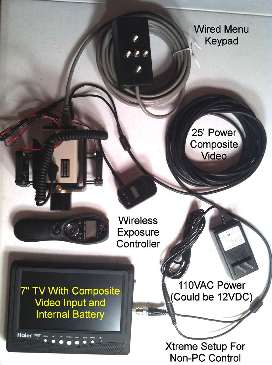
21 FIGURE 20 For non-computer control of an Xtreme or Xtreme X2, one must purchase at a minimum the Wireless Exposure Controller (WEC). The WEC is composed of a hand-held wireless transmitter and its matching receiver that is plugged into the side socket on the MallinCam. Without computer control
22 or the WEC, an Xtreme or Xtreme X2 is limited to a 2.1 second exposure. Once the WEC Receiver is connected to the 4-Pin Socket on the side of the Xtreme or Xtreme X2, full exposure function is restored. To facilitate the adjusting of the Menu, the same Wired Menu Keypad used on the Hyper Plus and VSS can be connected to the Auxiliary Port on the camera. Figure 21 shows an Xtreme set up for non-computer control.
23 FIGURE 21
24 Hopefully this document will help explain the function of the different components of a MallinCam System and assist those in setting theirs up quickly to achieve First MallinCam Light. Jack Huerkamp Jack s Astro Accessories, LLC.
Quick Setup Guide. DCX-500i / DCX-1000i / DCX-1500i Projectors with WC-Pro Scaler. Preliminary
 Quick Setup Guide DCX-500i / DCX-1000i / DCX-1500i Projectors with WC-Pro Scaler Preliminary Table of Contents Introduction... 1 Connecting the Projector... 1 Installing the Primary Lens... 2 Connecting
P-2 Installing the monitor (continued) Carry out as necessary
 Carry out as necessary") P-2 Installing the monitor (continued) Carry out as necessary Using the monitor without the bezel MDT552S satisfies the UL requirements as long as it is used with the bezel attached. When using the monitor
P-2 Installing the monitor (continued) Carry out as necessary Using the monitor without the bezel MDT552S satisfies the UL requirements as long as it is used with the bezel attached. When using the monitor
epos & Security Essentials Trade ONLY ONLY Trade Catalogue Call us Now on Visit Our Website
 epos & Security Essentials Trade Catalogue Trade ONLY ONLY Call us Now on 024 7668 8590 Visit Our Website www.tronicextreme.co.uk 2 Item No. 10595 Item No. 10596 TP-101 All in One Touch Screen epos System
AC335A. VGA-Video Ultimate Plus BLACK BOX Back Panel View. Remote Control. Side View MOUSE DC IN OVERLAY
 AC335A BLACK BOX 724-746-5500 VGA-Video Ultimate Plus Position OVERLAY MIX POWER FREEZE ZOOM NTSC/PAL SIZE GENLOCK POWER DC IN MOUSE MIC IN AUDIO OUT VGA IN/OUT (MAC) Remote Control Back Panel View RGB
AC334A. VGA-Video Ultimate BLACK BOX Remote Control. Back Panel View. Side View MOUSE DC IN BLACK BOX ZOOM/FREEZE POWER
 AC334A BLACK BOX 724-746-5500 VGA-Video Ultimate BLACK BOX 724-746-5500 Zoom Position PAL ZOOM/FREEZE POWER FREEZE ZOOM NTSC/PAL SIZE RESET POWER Size Power Remote Control DC IN MOUSE MIC IN AUDIO OUT
Kramer Electronics, Ltd. USER MANUAL. Model: VS x 1 Sequential Video Audio Switcher
 Kramer Electronics, Ltd. USER MANUAL Model: VS-120 20 x 1 Sequential Video Audio Switcher Contents Contents 1 Introduction 1 2 Getting Started 1 2.1 Quick Start 2 3 Overview 3 4 Installing the VS-120 in
Single sensor setup with NIVEL210
 Single sensor setup with NIVEL210 Essential Items: 576 198 NIVEL210 RS232 748 335 Cable, Lemo 0 power supply cable Lemo 1 802 902 Cable, Lemo 0 722 409 Power supply plus power cords 802 902 576 198 748
Displays Open Frame Monitor Model Number: AND-TFT-150Bxx
 Displays 15.0 Open Frame Monitor Model Number: AND-TFT-150Bxx The AND-TFT-150Bxx 15.0 Open Frame Monitor series are rugged, high performance Industrial LCD Monitors, designed for commercial and industrial
Electronic Equipment Manual For 101, 102, 301 & 302 Azrieli Theatre For further information, please visit our website at:
 Electronic Equipment Manual For 101, 102, 301 & 302 Azrieli Theatre For further information, please visit our website at: http://www.carleton.ca/ims/ 2 TABLE OF CONTENTS: Topic Page # Logging onto the
YAMAHA 03D SERIAL AUDIO MIXER
 TECH NOTE Fastrack VS Verion 1.0 and later YAMAHA 03D SERIAL AUDIO MIXER The Fastrack VS hybrid editing system interfaces to the 03D Serial Audio Mixer with a 6-pin DIN to 9-pin RS-422 serial control cable
1 Unpack the projector. Quick Setup. EPSON PowerLite S1+ Your projector comes with the following items:
 EPSON PowerLite S1+ Quick Setup 1 Unpack the projector Your projector comes with the following items: Projector Power cord Computer cable Computer Projector Projector remote control Presentation remote
1CHDVRD1 USER MANUAL. These instructions apply to unit model 1CHDVRD1 only. Please read carefully before use.
 These instructions apply to unit model 1CHDVRD1 only. Please read carefully before use. 1CHDVRD1 USER MANUAL Description Description... 03 Features... 03 Notes... 03 Packing List... 04 Technical Specifications...
SBL /SBLG Series Wireless Clock
 Installation Manual V8.3 SBL /SBLG Series Wireless Clock Current as of August 2018 The Sapling Company, Inc. SBL and SBLG Series Wireless Clocks Table of Contents Table of Contents 2 Important Safety Instructions
Mortara X-Scribe Tango+ Interface Notes
 Mortara X-Scribe Tango+ Interface Notes To setup Tango+ with the X-Scribe stress system, simply follow the directions below. 1. Verify Correct RS-232 and ECG Trigger Cables RS-232 Cable used to communicate
6.4 Chassis Monitor Model Number: LCM0642xx. SPEC No.: SAS Version: 0.0 Issue Date: April 16, Introduction:
 6.4 Chassis Monitor Model Number: LCM0642xx This product is RoHS compliant SPEC No.: SAS-0908003 Version: 0.0 Issue Date: April 16, 2010 1. Introduction: 1.1 About the Product The LCM0642xx 6.4 Chassis
Manual Version Ver 1.0
 The BG-3 & The BG-7 Multiple Test Pattern Generator with Field Programmable ID Option Manual Version Ver 1.0 BURST ELECTRONICS INC CORRALES, NM 87048 USA (505) 898-1455 VOICE (505) 890-8926 Tech Support
AudioJoG (TM) Rack 8 Connector PIN LABEL LED Connector PIN LABEL LED. Operations Manual 3.5mm & 6.35mm Mono/Stereo Jacks
 Rack 8 Connector PIN LABEL LED Connector PIN LABEL LED. Operations Manual 3.5mm & 6.35mm Mono/Stereo Jacks") LED/Connector pin identification table AudioJoG (TM) Rack 8 Connector PIN LABEL LED Connector PIN LABEL LED Operations Manual 3.5mm & 6.35mm Mono/Stereo Jacks 3,4,5 pole XLR Male & Female 3,5 & 8 pole
LED/Connector pin identification table AudioJoG (TM) Rack 8 Connector PIN LABEL LED Connector PIN LABEL LED Operations Manual 3.5mm & 6.35mm Mono/Stereo Jacks 3,4,5 pole XLR Male & Female 3,5 & 8 pole
Ten-Tec (865) Service Department:(865)
 Service Department:(865)") Ten-Tec (865) 453-7172 Service Department:(865) 428-0364 Installation Instructions for Ten-Tec Jupiter AT538K Tuner Kit The installation of the AT538K is divided into two steps. The first step is to reprogram
Ten-Tec (865) 453-7172 Service Department:(865) 428-0364 Installation Instructions for Ten-Tec Jupiter AT538K Tuner Kit The installation of the AT538K is divided into two steps. The first step is to reprogram
Instruction Manual for Electronic Blowers and Flashboards
 Instruction Manual for Electronic Blowers and Flashboards These instructions cover both the table model 17212 table top Electronic Bingo Blower (Fig 1) and the 17213 floor model Electronic Bingo Blower
CAR-5N / CAR-5P Video to RGB Converter for CAR display. Operation Manual
 CAR-5N / CAR-5P Video to RGB Converter for CAR display Operation Manual TABLE OF CONTENTS 1. Introduction... 1 2. Features... 1 3. Package Contents... 1 4. Operation Controls and Functions... 2 4.1 Front
VNS2200 Amplifier & Controller Installation Guide
 VNS2200 Amplifier & Controller Installation Guide VNS2200 Amplifier & Controller Installation 1. Determine the installation location for the VNS2200 device. Consider the following when determining the
DVB-C25. Compatible with navigation systems Mercedes Benz Comand 2.5
 dvblogic DVB-T Tuner Compatible with navigation systems Mercedes Benz Comand 2.5 Product features full plug and play vehicle-specific dual DVB-T Tuner with two active DVB-T glass-mount antennas integrated
EdgeConnect Module Quick Start Guide ITERIS INNOVATION FOR BETTER MOBILITY
 EdgeConnect Module Quick Start Guide ITERIS INNOVATION FOR BETTER MOBILITY 493456301 Rev B April 2009 Table of Contents Installation... 1 Setup... 2 Operation... 4 Live Video... 4 Video Settings... 5 Network
FLAT DISPLAY TECHNOLOGY
 15.0 Open Frame Monitor Model Number: LOF1506xx This product is RoHS compliant SPEC No.: SAS-1008002 Version: 0.0 Issue Date: September 6, 2010 1. Introduction: 1.1 About the Product The LOF1506xx 15.0
BBV REAL TIME HQ DISPLAY QUAD MANUAL
 BBV REAL TIME HQ DISPLAY QUAD MANUAL Building Block Video Ltd., 17 Apex Park, Diplocks Industrial Estate, Hailsham, East Sussex, BN27 3JU, UK. Tel:+44 (0)1323 842727 Fax:+44 (0)1323 842728 Support:+44(0)1323
GWL/ Power Group Technology Solutions Stay Powered for the Future
 GWL/ Power Group Technology Solutions Stay Powered for the Future BMS2405 CONNECTION GUIDE: This is simple step-by-step manual how to CONNECT AND proceed basic SETUP of BMS2405. In following example connection
2.4GHZ Digital Wireless Reversing Camera Kit
 2.4GHZ Digital Wireless Reversing Camera Kit I. Safety precautions for the product The receiving host is installed on the console of the car securely. Do not impact the LCD screen of the receiving host.
Instruction Manual for the & Electronic Bingo Blower
 Instruction Manual for the 17212 & 17214 Electronic Bingo Blower The directions in this manual when referring to the 17212 are referring to software version 2.83 (you can find what version your blower
Video Server SED-2100R/S. Quick Installation Guide
 Video Server SED-2100R/S Quick Installation Guide Feb.10,2006 1 1 Getting Started 1.1 PACKAGE CONTENTS SED-2100 Warranty Card Software CD Hook up & Screws Terminal Blocks for Power & DI/O Power Adaptor
PRESET 10 PORTABLE OWNERS MANUAL
 PRESET 10 PORTABLE OWNERS MANUAL Doug Fleenor Design 396 Corbett Canyon Road Arroyo Grande, CA 93420 (805)-481-9599 Software Version 2.0 Revision 4 February, 2006 > Serial Number 062119 PRODUCT DESCRIPTION
1 Unpack the projector. Quick Setup. Epson PowerLite 62c/82c. User s Guide. You should have the following items: Computer cable. Power cord.
 Epson PowerLite 62c/82c Quick Setup 1 Unpack the projector You should have the following items: Projector Power cord Computer cable Projector remote control Password protect sticker User s Guide CD-ROM
DT1-PCM21. for Porsche PCM2.1 navigation systems
 Product features dvblogic DVB-T Tuner for Porsche PCM2.1 navigation systems Full plug and play vehicle-specific dual DVB-T Tuner + USB-AV-Player DVB-T-Tuner MPEG4 compatible (HD) USB-AV-Player for USB-media
HR7012M / HR7012S. Custom Vehicle Headrests with 7 Slim Style LED LCD Satellite Monitors or Built-in DVD Player for Rear Entertainment HR7012M
 S S P HR7012M / HR7012S Custom Vehicle Headrests with 7 Slim Style LED LCD Satellite Monitors or Built-in DVD Player for Rear Entertainment HR7012M HR7012S Installation Guide 128-9047 IMPORTANT NOTICE
VNS2210 Amplifier & Controller Installation Guide
 VNS2210 Amplifier & Controller Installation Guide VNS2210 Amplifier & Controller Installation 1. Determine the installation location for the VNS2210 device. Consider the following when determining the
Home Monitoring. Wired Color Camera. User Manual. For indoor/outdoor use. Do not use in wet locations.
 45231 Home Monitoring Wired Color Camera User Manual For indoor/outdoor use. Do not use in wet locations. www.jascoproducts.com 1-800-654-8483 2 Thank you for purchasing the GE 45231 Wired Color Camera.
Quick and Easy Set-up Manual. DB-300tm. and. DB-600tm
 Blazing SPL Display DB-300tm and DB-600tm 22410 70th Avenue West Mountlake Terrace, WA 98043 Phone 425-775-8461 Fax 425-778-3166 www.audiocontrol.com 1998 AudioControl. All rights reserved. P/N 9130490
Signature User Manual. Signature Camera. [Version 2.0] Michael Burns Rock Mallin
![Signature User Manual. Signature Camera. [Version 2.0] Michael Burns Rock Mallin](/thumbs/81/82851624.jpg "Signature User Manual. Signature Camera. [Version 2.0] Michael Burns Rock Mallin") Signature Camera Revision Sheet [Version 2.0] Michael Burns Rock Mallin [Signature User Manual] This document will introduce you to the wonders of the Mallincam Signature Camera. It will include instructions
Signature Camera Revision Sheet [Version 2.0] Michael Burns Rock Mallin [Signature User Manual] This document will introduce you to the wonders of the Mallincam Signature Camera. It will include instructions
2 Connect your video source
 EX90 2 Connect your video source Quick Setup Connect the projector to a computer or video source using any of the available connections shown below. Check the connectors on your video equipment. If more
TV CHANNEL INSTALLATION
 LCD TV TV CHANNEL ATION Immediately after unpacking and plugging in your new television, run the auto program function to set up the TV for the broadcast or cable channels available in your area. If you
Connevans.info. DeafEquipment.co.uk. This product may be purchased from Connevans Limited secure online store at
 Connevans.info Solutions to improve the quality of life Offering you choice Helping you choose This product may be purchased from Connevans Limited secure online store at www.deafequipment.co.uk DeafEquipment.co.uk
Table of Contents. Versa TILE & Versa DRIVE D2 Quick Start Manual
 Versa TILE & Versa DRIVE D2 Table of Contents 1. Introduction 2 2. Versa TILE Assembly & Cabling 2 3. Computer & Versa DRIVE Connections 2 4. RasterMAPPER 3 5. Buffer Board 4 6. Testing the System 5 7.
A. All equipment and materials used shall be standard components that are regularly manufactured and used in the manufacturer s system.
 SPECTRA MINI SERIES DOME SYSTEM, NTSC/PAL TECHNICAL SPECIFICATIONS SECURITY SYSTEM DIVISION -- 28 ELECTRONIC SAFETY AND SECURITY LEVEL 1 28 20 00 ELECTRONIC SURVEILLANCE LEVEL 2 28 23 00 VIDEO SURVEILLANCE
OPTICAL POWER METER WITH SMART DETECTOR HEAD
 OPTICAL POWER METER WITH SMART DETECTOR HEAD Features Fast response (over 1000 readouts/s) Wavelengths: 440 to 900 nm for visible (VIS) and 800 to 1700 nm for infrared (IR) NIST traceable Built-in attenuator
DH7-DK QUICKSTART GUIDE. DH7 4K Support HDMI On-Camera Field Monitor Deluxe Kit
 DH7-DK QUICKSTART GUIDE DH7 4K Support HDMI On-Camera Field Monitor Deluxe Kit What s Included 1 x DH7 Monitor 1 x AC Adapter 1 x Camera Shoe Mount 1 x Screen Cleaning Wipe 1 x Screen Protection Film 1
Model CMX3838A2 AV Matrix Switch with DSP audio (firmware 1.0)
") Model CMX3838A2 AV Matrix Switch with DSP audio (firmware 1.0) Overview: This product is a full featured video & audio matrix switch. It is most commonly used to independently distribute video & audio
Model CMX3838A2 AV Matrix Switch with DSP audio (firmware 1.0) Overview: This product is a full featured video & audio matrix switch. It is most commonly used to independently distribute video & audio
Composite to HDMI Scaler
 Composite to HDMI Scaler GTV-COMPSVID-2-HDMIS User Manual Version A2 gefen.com ASKING FOR ASSISTANCE Technical Support: Telephone Email 1-707-283-5900 1-800-472-5555 support@gefen.com Technical Support
Welch Allyn CardioPerfect Workstation Tango+ Interface Notes
 Welch Allyn CardioPerfect Workstation Tango+ Interface Notes To setup Tango+ with the CardioPerfect stress system, simply follow the directions below. 1. Verify Correct RS-232 and ECG Trigger Cables RS-232
Dissolve Control Programming : Projector/Dissolve Control Hook-Up
 Product Information Title: Operating Equipment: Dissolve Control Programming Projector/Dissolve Control Hook-up Sync Track Hook-up Converting Tapes to Digital Sync Signals Recording Signals 80 Vs 140 Slide
SAPLING WIRED SYSTEM
 SAPLING WIRED SYSTEM Sapling 2-Wire System DESCRIPTION The Sapling 2-Wire System is one of the most innovative and advanced wired systems in the synchronized time industry. It starts with the SMA Series
Dual PAL or NTSC Video to RGB Converter (One way) with 12V Relay Switch Operation Manual
 with 12V Relay Switch Operation Manual") Dual PAL or NTSC Video to RGB Converter (One way) with 12V Relay Switch Operation Manual Introduction This unit converts video signals from NTSC/PAL/SECAM into RGB/Sync or RGsB (Sync On Green) to allow
Dual PAL or NTSC Video to RGB Converter (One way) with 12V Relay Switch Operation Manual Introduction This unit converts video signals from NTSC/PAL/SECAM into RGB/Sync or RGsB (Sync On Green) to allow
DVB-PCM30. for Porsche PCM3.0 and 3.1 navigation systems
 dvblogic DVB-T Tuner for Porsche PCM3.0 and 3.1 navigation systems Product features full plug and play vehicle-specific dual DVB-T Tuner with two active DVB-T glass-mount antennas integrated into and controllable
AZ DISPLAYS, INC. COMPLETE LCD SOLUTIONS SPECIFICATIONS FOR 15.0 OPEN FRAME MONITOR
 AZ DISPLAYS, INC. COMPLETE LCD SOLUTIONS SPECIFICATIONS FOR 15.0 OPEN FRAME MONITOR PART NUMBER: AOM150X03 SERIES DATE: SEPT 04, 2008 1. Introduction: 1.1 About the Product AOM150Xxx 15.0 Open Frame Monitor
Delvcam DELV-3GHD-17RM
 Delvcam DELV-3GHD-17RM 17.3" High Resolution 3G-SDI/HDMI Rackmount LCD Video Monitor IMPORTANT SAFETY INSTRUCTIONS Read manual before using this product. Keep manual for future reference. Do not place
Quick Setup 1 Unpack the projector
 PowerLite 410W Quick Setup 1 Unpack the projector You should have the following items: Projector and lens cover Power cord Remote control and batteries Computer cable Projector CD-ROMs Password protected
YAMAHA 03D SERIAL AUDIO MIXER
 TECH NOTE Fastrack VS Verion 1.0 and later YAMAHA 03D SERIAL AUDIO MIXER The Fastrack VS hybrid editing system interfaces to the 03D Serial Audio Mixer with a 6-pin DIN to 9-pin RS-422 serial control cable
DVB-C20. Compatible with navigation systems Mercedes Benz Comand 2.0 Comand APS CD Comand APS 220
 dvblogic DVB-T Tuner Compatible with navigation systems Mercedes Benz Comand 2.0 Comand APS CD Comand APS 220 Product features full plug and play vehicle-specific dual DVB-T Tuner with two active DVB-T
User Manual MODEL: KK1500-TR. Touch Display LCD Monitor. Installation Guide. 15 Resistive Touch LCD Monitor
 Touch Display LCD Monitor User Manual Installation Guide 15 Resistive Touch LCD Monitor MODEL: KK1500-TR i-tech Company LLC TOLL FREE: (888) 483-2418 EMAIL: info@itechlcd.com WEB: www.itechlcd.com User
UNDER TABLE 4X1 HDMI SWITCHER
 UNDER TABLE 4X1 HDMI SWITCHER Welcome! Everyone at Altinex greatly appreciates your purchase of the UT260-041. We are confident that you will find it to be reliable and easy to use. If you need support,
INSTALLATION INSTRUCTIONS FOR
 INSTALLATION INSTRUCTIONS FOR MODEL 2240LED www.sportablescoreboards.com 1 Table of Contents 8 X 7 INDOOR SCOREBOARD... 3 THE SCOREBOARD SYSTEM SHOULD INCLUDE THE FOLLOWING PARTS:... 3 INSTRUCTIONS FOR
Model Colorado Ultra Wide Bandwidth HDTV Matrix Switch
 HDTV Supply, Inc www.hdtvsupply.com Model Colorado Ultra Wide Bandwidth HDTV Matrix Switch Overview: This product is a full featured video & audio matrix switch. It is most commonly used to independently
Main Products. Cable Assemblies Wire Harnesses Raw Cables. Connectors
 About BMA BMA technology Ltd was found in Hong Kong in 2009. Our factory is located in Guangdong, China. With the 10,000m 2 production area, we are able to hold 500 workers during the peak season. Our
Wall Ball Setup / Calibration
 Wall Ball Setup / Calibration Wall projection game 1 Table of contents Wall Projection Ceiling Mounted Calibration Select sensor and display Masking the projection area Adjusting the sliders What s happening?
RMS 8424S Quick Start
 VIEWSIZE THE WORLD RMS 8424S Quick Start Standard 4 unit rack mount size 8 inch LCD 2 1024 3 (RGB) 600 16:9 / 4:3 adjustable SDI/HDMI embedded audio output via 3.5mm earphone socket Support SDI/DVI audio
PRELIMINARY. Orbis CU. Preliminary Data Sheet!
 Digital Control Unit Order # 725.692 Preliminary Data Sheet! FEATURES Microphone units can be connected in two lines or in a ring Connection of a maximum of 100 microphone units (50 per line) without redundancy
Quad Video Switching Box User Manual
 Quad Video Switching Box User Manual The Solution for Vehicle safety Table of Contents PRECAUTIONS 3 IDENTIFYING THE PARTS 4 INSTALLATION DIAGRAM...5 Camera or video input/output.. 5 Camera or video display...6
AUTOMATIC VIDEO LOSS A/B SWITCH
 CG-X AUTOMATIC VIDEO LOSS A/B SWITCH INSTRUCTION BOOK IB647502 TABLE OF CONTENTS DESCRIPTION 2 MOUNTING INSTRUCTIONS 3 HOW TO CABLE THE CG-X 3 POWER SUPPLY INSTALLATION 3 OPERATION 3 CARE AND MAINTENANCE
ivw-fd122 Video Wall Controller MODEL: ivw-fd122 Video Wall Controller Supports 2 x 2 Video Wall Array User Manual Page i Rev. 1.
 MODEL: ivw-fd122 Video Wall Controller Supports 2 x 2 Video Wall Array User Manual Rev. 1.01 Page i Copyright COPYRIGHT NOTICE The information in this document is subject to change without prior notice
Audio Integration Note
 OneHome Audio Integration Note Manufacturer: Russound Model Number(s): CAV6.6 / CAM6.6 Comments: Document Revision Date: 6/25/2005 OVERVIEW AND SUPPORTED FEATURES The following features are supported:
r.link Video-inserter RL5-UCON7-500 Compatible with Fiat vehicles with Uconnect 7inch infotainment
 r.link Video-inserter RL5-UCON7-500 Compatible with Fiat vehicles with Uconnect 7inch infotainment Video-inserter with 1 video input and 1 rear-view camera input Product features Video-inserter for factory-infotainment
HDX 4K. Quick Start Guide. Connect power. Download Product Manual
 HDX K Quick Start Guide Download Product Manual Product manuals and documentation are available online at www.barco.com/td/r000 Registration may be required; follow the instructions given on the website.
S7H-DK S7H 7" High Bright Monitor Deluxe Kit
 S7H-DK S7H 7" High Bright Monitor Deluxe Kit QUICKSTART GUIDE What s Included 1 x S7H Monitor 1 x Camera Shoe Mount 1 x Neoprene Sleeve 1 x Mini-XLR to P-TAP Cable 2 x DV Battery Plate 1 x DV Battery 1
DIVERSITY DVB-T RECEIVER (DDR)
") User s Manual The most important thing we build is trust. DIVERSITY DVB-T RECEIVER (DDR) Cobham Surveillance GMS Products 1916 Palomar Oaks Way Ste 100 Carlsbad, CA 92008 100-M0062X2 T: 760-496-0055 05/15/09
User s Manual The most important thing we build is trust. DIVERSITY DVB-T RECEIVER (DDR) Cobham Surveillance GMS Products 1916 Palomar Oaks Way Ste 100 Carlsbad, CA 92008 100-M0062X2 T: 760-496-0055 05/15/09
AN2 Series. 900tvl. CMOS Technology High Resolution Sensor. elinetechnology.com P/N 01.BSM V1.0
 AN2 Series 900tvl CMOS Technology High Resolution Sensor P/N 01.BSM.16.2000030 V1.0 Product Made in China under ISO9001 & ISO1400 standards Manual Printed in China v1.0 elinetechnology.com CAUTION RISK
BMW12N-DYNAMIC KIT NTV-KIT717
 3950 NW 120 th Ave, Coral Springs, FL 33065 TEL 561-955-9770 FAX 561-955-9760 www.nav-tv.com info@nav-tv.com BMW12N-DYNAMIC KIT NTV-KIT717 Screen Connector Overview The BMW12-N kit interfaces 2 video inputs
DATA/SPEC SHEET 16-CHANNEL HYBRID DIGITAL VIDEO RECORDER. Built for Reliability, Usability, and Low Cost of Ownership.
 DATA/SPEC SHEET V920 KOLLECTOR - PRODUCT FORCE DESCRIPTION 16-CHANNEL HYBRID DIGITAL VIDEO RECORDER Configured with ViconNet Video Management Software (VMS) Scalable from one to hundreds of recorders Support
UNFOLD THE BASE. Quick Start Guide CONTENTS INSTALLING LCD TV ON THE WALL
 Quick Start Guide English CONTENTS INSTALLING LCD TV ON THE WALL.. UNFOLD THE BASE............... TV CHANNEL INSTALLATION........ PRESENTATION OF THE LCD TV..... ACCESSORIES.................... BATTERY
Standard Digital Terminal High-Definition Digital Terminal. User Guide
 Standard Digital Terminal High-Definition Digital Terminal User Guide ILL-GDA-STD-001-0709 IN THIS GUIDE IMPORTANT RULES FOR SAFE OPERATION... 4 AVAILABLE ILLICO TERMINALS... 5 REMOTE CONTROLS... 17 CONNECTIONS...
VXF7 QUICKSTART GUIDE. 7" 4K Full HD HDMI/3G-SDI On-Camera Monitor
 VXF7 QUICKSTART GUIDE 7" K Full HD HDMI/G-SDI On-Camera Monitor What s Included x VXF7 Monitor x AC Adapter x Camera Shoe Mount (SM-0) x Screen Cleaning Wipe x Screen Protector x Sunhood x Canon E6 Battery
DVB-LR10. Compatible with Land Rover touch-screen navigation systems version 2
 dvblogic DVB-T Tuner Compatible with Land Rover touch-screen navigation systems version 2 Product features full plug and play vehicle-specific dual DVB-T Tuner with two active DVB-T glass-mount antennas
INSTALLATION AND OPERATION INSTRUCTIONS EVOLUTION VIDEO DISTRIBUTION SYSTEM
 INSTALLATION AND OPERATION INSTRUCTIONS EVOLUTION VIDEO DISTRIBUTION SYSTEM ATTENTION: READ THE ENTIRE INSTRUCTION SHEET BEFORE STARTING THE INSTALLATION PROCESS. WARNING! Do not begin to install your
User Manual 15" LCD Open frame SAW Touch Monitor KOT-0150US-SA4W. Table of Contents
 User Manual 15" LCD Open frame SAW Touch Monitor KOT-0150US-SA4W Table of Contents Chapter 1. Introduction...2 1.1 Product Description 1.2 About the Product Chapter 2. Installation and Setup...2 2.1 Unpacking
2 Connect your video source
 PowerLite 822+/83+ 2 Connect your video source Quick Setup Connect the projector to a computer or video source using any of the available connections shown below. Check the connectors on your video equipment.
Getting started with
 PART NO. CMA11 3 MADE IN CHINA 1. Measuring CAT II 2. Max. voltage 250V ~ 3. Max. current 71 Amp Getting started with Electricity consumption & Solar PV generation monitoring single phase, for homes fitted
Safety warning Important Safety Instructions. Wall Mount Specifications. Electronic Program Guide. Lock Menu 18. PVR File System
 LT-32N370Z 32 INPUT Safety warning Important Safety Instructions Wall Mount Specifications Electronic Program Guide Lock Menu 18 PVR File System 11 11 11 14 15 16 17 19 20 21 21 22 23 24 25 INPUT AAA
Intelligent Security and Fire Ltd
 User Manual Product ranges covered by this manual Vi-P14 Vi-P14A Document Reference Date Firmware Vi-Q4C1 Viq601a.doc 26/11/2009 From Viq001a21 Videoswitch Telephone 01252-851510 Ocean House, Redfields
LinTronic. TableTop series. Hardware version 6. Updated
 Updated 151120 TableTop series Hardware version 6 We keep expanding Hardware 6 Introduced 2011 Hardware 5 Introduced 2006 Hardware 4 Introduced 2003 32KByte 128KByte 256KByte What's new? Feature Hardware
Prototyping & Engineering Electronics Kits Magic Mandala Kit Guide
 Prototyping & Engineering Electronics Kits Magic Mandala Kit Guide odysseyboard.com Please refer to www.odysseyboard.com for a PDF updated version of this guide. Magic Mandala Guide version 1.0, February,
ivw-fd133 Video Wall Controller MODEL: ivw-fd133 Video Wall Controller Supports 3 x 3 and 2 x 2 Video Wall Array User Manual Page i Rev. 1.
 MODEL: ivw-fd133 Video Wall Controller Supports 3 x 3 and 2 x 2 Video Wall Array User Manual Rev. 1.01 Page i Copyright COPYRIGHT NOTICE The information in this document is subject to change without prior
Operating Instructions
 CNTX Contrast sensor Operating Instructions CAUTIONS AND WARNINGS SET-UP DISTANCE ADJUSTMENT: As a general rule, the sensor should be fixed at a 15 to 20 angle from directly perpendicular to the target
LAN Network Tester. Operating Manual. Part No TRIAX - your ultimate connection
 LAN Network Tester Part No. 157011 Operating Manual TRIAX - your ultimate connection Safety and Disposal The LAN Network Tester operates off 6V DC only. Only use the internal, battery powered, 6V power
Do not remove screws, cover, or cabinet. There are no user serviceable parts inside. Refer servicing to qualified service personnel.
 SAFETY NOTES To reduce the risk of electrical shocks, fire, and related hazards: Do not remove screws, cover, or cabinet. There are no user serviceable parts inside. Refer servicing to qualified service
SX7. Saga 7" Super Bright HDMI/3G-SDI Field Monitor with 3D-LUTs. Quick Start Guide. What s Included CHECKED BY
 SX7 Quick Start Guide Saga 7" Super Bright HDMI/3G-SDI Field Monitor with 3D-LUTs What s Included 1 x Saga X7 Monitor 1 x V-Mount Plate (Attached) 1 x Mini-XLR to P-TAP Cable 1 x Dual Sony L Battery Adapter
DVB-E65-TV. Compatible with BMW E65 Professional navigation systems with 8.8 monitor
 dvblogic DVB-T Tuner Compatible with BMW E65 Professional navigation systems with 8.8 monitor Vehicles with factory TV-tuner port (Factory TV-tuner must be uninstalled) Product features Full plug and play
FPV PRO RACE EDITION TRI-DIVERSITY VIDEO CONTROLLER
 DIVERSITY DEMON FPV PRO RACE EDITION TRI-DIVERSITY VIDEO CONTROLLER Diversity Demon is a video controller that is used to bridge three wireless video receivers together. Multiple receivers are used to
How I connect to Night Skies Network (NSN) using Mallincam Xtreme with Miloslick Software
 using Mallincam Xtreme with Miloslick Software") How I connect to Night Skies Network (NSN) using Mallincam Xtreme with Miloslick Software Introduction I found that when I first started connecting to NSN, things started happening too fast for me to keep
How I connect to Night Skies Network (NSN) using Mallincam Xtreme with Miloslick Software Introduction I found that when I first started connecting to NSN, things started happening too fast for me to keep
T L Audio. User Manual C1 VALVE COMPRESSOR. Tony Larking Professional Sales Limited, Letchworth, England.
 T L Audio User Manual C1 VALVE COMPRESSOR Tony Larking Professional Sales Limited, Letchworth, England. Tel: 01462 490600. International +44 1462 490600. Fax: 01462 490700. International +44 1462 490700.
OWNERS MANUAL LUNATEC V3 MICROPHONE PREAMPLIFIER AND A/D CONVERTER
 OWNERS MANUAL LUNATEC V3 MICROPHONE PREAMPLIFIER AND A/D CONVERTER LUNATEC 35 +48 35 +48 30 40 30 40 0 25 45 25 45 3 192 1 1 6 176.4 20 50 20 50 9 96 12 PEAK 88.2 55 55 RESET 48 10 60 2 10 60 2 21 44.1
QUAD Camera Inputs with 8 display options (see pg 14-17) Handbook & Instructions. ...and more!
 Handbook & Instructions. ...and more!") QUAD040 Handbook & Instructions Useful compact quad unit that can be wall mounted or desk mounted. Multiple display options make it indispensable to the professional CCTV engineer. 4 Camera Inputs with
QUAD040 Handbook & Instructions Useful compact quad unit that can be wall mounted or desk mounted. Multiple display options make it indispensable to the professional CCTV engineer. 4 Camera Inputs with
INSTALLATION & USER GUIDE
 INSTALLATION & USER GUIDE Digidim 458 8-Channel Dimmer STEP 1 Assemble Dimmer Unit STEP 2 Mount Dimmer Chassis STEP 3 Electrical Installation STEP 4 Attach Module and Make Connections STEP 5 Replace Cover
1995 Metric CSJ SPECIAL SPECIFICATION ITEM 6031 SINGLE MODE FIBER OPTIC VIDEO TRANSMISSION EQUIPMENT
 1995 Metric CSJ 0508-01-258 SPECIAL SPECIFICATION ITEM 6031 SINGLE MODE FIBER OPTIC VIDEO TRANSMISSION EQUIPMENT 1.0 Description This Item shall govern for the furnishing and installation of color Single