EKT 121/4 ELEKTRONIK DIGIT 1
|
|
|
- Polly Turner
- 6 years ago
- Views:
Transcription
1 EKT 121/4 ELEKTRONIK DIGIT 1 Kolej Universiti Kejuruteraan Utara Malaysia Bistable Storage Devices and Related Devices
2 Introduction Latches and flip-flops are the basic single-bit memory elements used to build sequential circuit with one or two inputs/outputs, designed using individual logic gates and feedback loops. Latches: The output of a latch depends on its current inputs and on its previous output and its change of state can happen at any time when its inputs change. Flip-Flop: The output of a flip-flop also depends on current inputs and its previous output but the change of state occurs at specific times determined by a clock input.
3 Latches: S-R R Latch Gate S-R S R Latch Gate D-LatchD Introduction Flip-Flops: Flops: Edge-Triggered Flip-Flop Flop (S-R, J-K, J D) Asynchronous Inputs Master-Slave Flip-Flop Flop Flip-Flop Flop Operating Characteristics Flip-Flop Flop Applications One-shots & The 555 Timer
4 Latches Type of temporary storage device that has two stable (bistable( bistable) ) states Similar to flip-flop flop the outputs are connected back to opposite inputs Main difference from flip-flop flop is the method used for changing their state S-R R latch, Gated/Enabled S-R S R latch and Gated D latch
5 S-R R (SET-RESET) Latch Active-HIGH input S-R Latch Active-LOW input S-R Latch
6 Logic symbols for the S-R and S-R latch.
7 Negative-OR equivalent of the NAND gate S-R latch
8

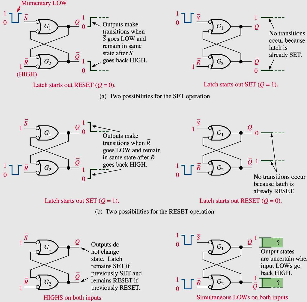
9 Truth table for an active-low input S-R latch
10 Assume that Q is initially LOW Waveforms
11 S-R R latch using NOR Gate Active-HIGH When the Set is high and Reset is low Q is high and Q is low
12 S-R R latch using NOR Gate (cont d) Active-HIGH Once Set is Q high, then with S and R both LOW nothing change.
13 S-R R latch using NOR Gate (cont d) Active-HIGH With Reset high and Set low the flip=flop give a Q high and a Q low.
14 S-R R latch using NOR Gate (cont d) Active-HIGH Toggling the Reset (LOW) changes nothing
15 S-R R latch using NOR Gate (cont d) Active-HIGH The state of both Set and Reset high is not allowed since it would give a illogical condition. ( INVALID! )
16 S-R R Latch truth table for NOR Gate Active-HIGH Input S R Q Q 0 0 Q Q hold condition set reset not allowed (Invalid)
17 S-R R Latch using NAND Gate Set high Reset low Q high Q low
18 S-R R Latch using NAND Gate (cont d) Reset high Set low give a Q low and Q high
19 S-R R Latch using NAND Gate (cont d) Both low no change
20 S-R R Latch using NAND Gate (cont d) Both Set and Reset high is not allowed but give both Q and Q as high
21 S-R R Latch truth table for NAND Gate S R Q Q 0 0 Q Q hold condition set reset not allowed
22 Gated S-R Latch A gate input is added to the S-R latch to make the latch synchronous. In order for the set and reset inputs to change the latch, the gate input must be active (high/enable). When the gate input is low, the latch remains in the hold condition.
23 A gated S-R latch.
24 Gated S-R latch waveform
25 Truth Table for Gated S-R S R Latch S R G Q Q Q Q Hold Q Q Hold Q Q Hold Q Q hold Q Q hold set reset not allowed
26 Gated D Latch (74LS75) The D (data) latch has a single input that is used to set and to reset the flip-flop. When the gate is high, the Q output will follow the D input. When the gate is low, the Q output will hold.
27 Gated S-R Latch Q output waveform if the inputs are as shown. The output follows the input when the gate is high but is in a hold when the gate is low.

28 Gated D Latch (74LS75)
29 Edge-triggered Flip-flop Logic Positive edge triggered and Negative edge-triggered All the above flip-flops have the triggering input called clock (CLK/C)
30 Clock Signals & Synchronous Sequential Circuits 1 Clock signal 0 Rising edges of the clock (Positive-edge triggered) Falling edges of the clock (Negative-edge triggered) Clock Cycle Time A clock signal is a periodic square wave that indefinitely switches values from 0 to 1 and 1 to 0 at fixed intervals.
31 Operation of a positive edge-triggered S-R flip-flop. (d) S=1, R=1 is invalid or not allowed
32 Example

33 A positive edge-triggered D flip-flop formed with an S-R flip-flop and an inverter. D CLK/C Q Q SET (stores a 1) RESET (stores a 0)
34 Example
35 Edge-triggered J-K J K flip-flop flop The edge-triggered J-K will only accept the J and K inputs during the active edge of the clock. The small triangle on the clock input indicates that the device is edge-triggered. A bubble on the clock input indicates that the device responds to the negative edge. no bubble would indicate a positive edge-triggered device.
36 Truth Table for J-K J K Flip Flop J K CLK Q Q 0 0 Q 0 Q 0 Hold Reset Set 1 1 Q 0 Q 0 Toggle (opposite state)
37 A simplified logic diagram for a positive edge-triggered J-K flip-flop.
38 Example: Positive edge-triggered
39 Example: Negative edge-triggered
40 Logic symbol for a J-K flip-flop with active- LOW preset and clear inputs.
41 Logic diagram for a basic J-K flip-flop with active-low preset and clear inputs.
42 Example:
43 A Master-Slave J-K Flip-Flop The J-K flip-flop has a toggle mode of operation when both J and K inputs are high.toggle means that the Q output will change states on each active clock edge. J, K and Cp are all synchronous inputs. The master-slave flip-flop is constructed with two latches. The master latch is loaded with the condition of the J-K inputs while the clock is high. When the clock goes low, the slave takes on the state of the master and the master is latched. The master-slave is a level-triggered device. The master-slave can interpret unwanted signals on the J-K inputs.

44 Basic logic diagram for a Master-Slave J-K flip-flop.
45 Pulse-triggered (master-slave) J-K flipflop logic symbols.
46 Truth Table for Master-Slave J-K Flip Flop J K CLK Q Q 0 0 Q 0 Q 0 Hold Reset Set 1 1 Q 0 Q 0 Toggle (opposite state)

47 Example: The flip-fop starts out RESET and the clock is active -LOW
48 Flip-Flop Applications Parallel Data Storage Frequency Division Counting
49 Application : Example of flip-flops used in a basic register for parallel data storage.
50 Application: The J-K flip-flop as a divide-by-2 device. Q is one-half the frequency of CLK.
51 Example : Two J-K flip-flops used to divide the clock frequency by 4. Q A is one-half and Q B is one-fourth the frequency of CLK.
52 Application: Flip-flops used to generate a binary count sequence. Two repetitions (00, 01, 10, 11) are shown.
53 ONE-SHOTS A monostable multivibrator, a device with only one stable state. Normally in its stable state and will change to its unstable state only when triggered. Once triggered, will remains in its unstable state for a predetermined length of time and will automatically returns to its stable state. The time it stays in its unstable state determines the pulse width of its output
54 A simple one-shot circuit.
55 Basic one-shot logic symbols. CX and RX stand for external components.
56 Nonretriggerable one-shot action.
57 Retriggerable one-shot action.
58 THE 555 TIMER Versatile and widely used IC because it can be configured in two different modes as either a monostable multivibrator (one-shots) or as an astable multivibrator (oscillator). An astable multivibrator has no stable states and therefore changes back and forth (oscillates) between two unstable states without any external triggering.

59 Internal functional diagram of a 555 timer (pin numbers are in parenthesis).

60 The 555 timer connected as a nonretriggerable one-shot.

61 The 555 timer connected as an astable multivibrator (oscillator).
62 Next week Sequential Circuit - Thank you -
EMT 125 Digital Electronic Principles I CHAPTER 6 : FLIP-FLOP
 EMT 125 Digital Electronic Principles I CHAPTER 6 : FLIP-FLOP 1 Chapter Overview Latches Gated Latches Edge-triggered flip-flops Master-slave flip-flops Flip-flop operating characteristics Flip-flop applications
Digital Fundamentals: A Systems Approach
 Digital Fundamentals: A Systems Approach Latches, Flip-Flops, and Timers Chapter 6 Traffic Signal Control Traffic Signal Control: State Diagram Traffic Signal Control: Block Diagram Traffic Signal Control:
LATCHES & FLIP-FLOP. Chapter 7
 LATCHES & FLIP-FLOP Chapter 7 INTRODUCTION Latch and flip flops are categorized as bistable devices which have two stable states,called SET and RESET. They can retain either of this states indefinitely
CHW 261: Logic Design
 CHW 26: Logic Design Instructors: Prof. Hala Zayed Dr. Ahmed Shalaby http://www.bu.edu.eg/staff/halazayed4 http://bu.edu.eg/staff/ahmedshalaby4# Slide Digital Fundamentals CHAPTER 7 Latches, Flip-Flops
Introduction. NAND Gate Latch. Digital Logic Design 1 FLIP-FLOP. Digital Logic Design 1
 2007 Introduction BK TP.HCM FLIP-FLOP So far we have seen Combinational Logic The output(s) depends only on the current values of the input variables Here we will look at Sequential Logic circuits The
Rangkaian Sekuensial. Flip-flop
 Rangkaian Sekuensial Rangkaian Sekuensial Flip-flop Combinational versus Sequential Functions Logic functions are categorized as being either combinational (sometimes referred to as combinatorial) or sequential.
CHAPTER 1 LATCHES & FLIP-FLOPS
 CHAPTER 1 LATCHES & FLIP-FLOPS 1 Outcome After learning this chapter, student should be able to; Recognize the difference between latches and flipflops Analyze the operation of the flip flop Draw the output
Chapter 5 Flip-Flops and Related Devices
 Chapter 5 Flip-Flops and Related Devices Chapter 5 Objectives Selected areas covered in this chapter: Constructing/analyzing operation of latch flip-flops made from NAND or NOR gates. Differences of synchronous/asynchronous
PGT104 Digital Electronics. PGT104 Digital Electronics
 1 Part 5 Latches, Flip-flop and Timers isclaimer: Most of the contents (if not all) are extracted from resources available for igital Fundamentals 10 th Edition 2 Latches A latch is a temporary storage
EKT 121/4 ELEKTRONIK DIGIT 1
 EKT 2/4 ELEKTRONIK DIGIT Kolej Universiti Kejuruteraan Utara Malaysia Sequential Logic Circuits - COUNTERS - LATCHES (review) S-R R Latch S-R R Latch Active-LOW input INPUTS OUTPUTS S R Q Q COMMENTS Q
Name Of The Experiment: Sequential circuit design Latch, Flip-flop and Registers
 EEE 304 Experiment No. 07 Name Of The Experiment: Sequential circuit design Latch, Flip-flop and Registers Important: Submit your Prelab at the beginning of the lab. Prelab 1: Construct a S-R Latch and
Digital Fundamentals 11/2/2017. Summary. Summary. Floyd. Chapter 7. Latches
 igital Fundamentals Tenth Edition Floyd hapter 7 2009 Pearson Education, Upper 2008 Pearson Saddle iver, Education N 07458. All ights eserved A latch is a temporary storage device that has two stable states
SEQUENTIAL LOGIC. Satish Chandra Assistant Professor Department of Physics P P N College, Kanpur
 SEQUENTIAL LOGIC Satish Chandra Assistant Professor Department of Physics P P N College, Kanpur www.satish0402.weebly.com OSCILLATORS Oscillators is an amplifier which derives its input from output. Oscillators
Logic Gates, Timers, Flip-Flops & Counters. Subhasish Chandra Assistant Professor Department of Physics Institute of Forensic Science, Nagpur
 Logic Gates, Timers, Flip-Flops & Counters Subhasish Chandra Assistant Professor Department of Physics Institute of Forensic Science, Nagpur Logic Gates Transistor NOT Gate Let I C be the collector current.
Review of Flip-Flop. Divya Aggarwal. Student, Department of Physics and Astro-Physics, University of Delhi, New Delhi. their state.
 pp. 4-9 Krishi Sanskriti Publications http://www.krishisanskriti.org/jbaer.html Review of Flip-Flop Divya Aggarwal Student, Department of Physics and Astro-Physics, University of Delhi, New Delhi Abstract:
FLIP-FLOPS AND RELATED DEVICES
 C H A P T E R 5 FLIP-FLOPS AND RELATED DEVICES OUTLINE 5- NAND Gate Latch 5-2 NOR Gate Latch 5-3 Troubleshooting Case Study 5-4 Digital Pulses 5-5 Clock Signals and Clocked Flip-Flops 5-6 Clocked S-R Flip-Flop
5: Sequential Logic Latches & Flip-flops
 5: Sequential Logic Latches & Flip-flops Introduction Memory Elements Pulse-Triggered Latch S-R Latch Gated S-R Latch Gated D Latch Edge-Triggered Flip-flops S-R Flip-flop D Flip-flop J-K Flip-flop T Flip-flop
PRE J. Figure 25.1a J-K flip-flop with Asynchronous Preset and Clear inputs
 Asynchronous Preset and Clear Inputs The S-R, J-K and D inputs are known as synchronous inputs because the outputs change when appropriate input values are applied at the inputs and a clock signal is applied
Flip-Flops and Related Devices. Wen-Hung Liao, Ph.D. 4/11/2001
 Flip-Flops and Related Devices Wen-Hung Liao, Ph.D. 4/11/2001 Objectives Recognize the various IEEE/ANSI flip-flop symbols. Use state transition diagrams to describe counter operation. Use flip-flops in
(CSC-3501) Lecture 7 (07 Feb 2008) Seung-Jong Park (Jay) CSC S.J. Park. Announcement
 Lecture 7 (07 Feb 2008) Seung-Jong Park (Jay) CSC S.J. Park. Announcement") Seung-Jong Park (Jay) http://www.csc.lsu.edu/~sjpark Computer Architecture (CSC-3501) Lecture 7 (07 Feb 2008) 1 Announcement 2 1 Combinational vs. Sequential Logic Combinational Logic Memoryless Outputs
Seung-Jong Park (Jay) http://www.csc.lsu.edu/~sjpark Computer Architecture (CSC-3501) Lecture 7 (07 Feb 2008) 1 Announcement 2 1 Combinational vs. Sequential Logic Combinational Logic Memoryless Outputs
RS flip-flop using NOR gate
 RS flip-flop using NOR gate Triggering and triggering methods Triggering : Applying train of pulses, to set or reset the memory cell is known as Triggering. Triggering methods:- There are basically two
Chapter 6. Flip-Flops and Simple Flip-Flop Applications
 Chapter 6 Flip-Flops and Simple Flip-Flop Applications Basic bistable element It is a circuit having two stable conditions (states). It can be used to store binary symbols. J. C. Huang, 2004 Digital Logic
Sequential Logic Basics
 Sequential Logic Basics Unlike Combinational Logic circuits that change state depending upon the actual signals being applied to their inputs at that time, Sequential Logic circuits have some form of inherent
Digital Fundamentals. Lab 5 Latches & Flip-Flops CETT Name: Date:
 Richland College School of Engineering & Technology Rev. 0 B. Donham Rev. 1 (7/2003) J. Horne Rev. 2 (1/2008) J. Bradbury Rev. 3 (7/2015) J. Bradbury Digital Fundamentals CETT 1425 Lab 5 Latches & Flip-Flops
Digital Logic Design Sequential Circuits. Dr. Basem ElHalawany
 Digital Logic Design Sequential Circuits Dr. Basem ElHalawany Combinational vs Sequential inputs X Combinational Circuits outputs Z A combinational circuit: At any time, outputs depends only on inputs
YEDITEPE UNIVERSITY DEPARTMENT OF COMPUTER ENGINEERING. EXPERIMENT VIII: FLIP-FLOPS, COUNTERS 2014 Fall
 YEDITEPE UNIVERSITY DEPARTMENT OF COMPUTER ENGINEERING EXPERIMENT VIII: FLIP-FLOPS, COUNTERS 2014 Fall Objective: - Dealing with the operation of simple sequential devices. Learning invalid condition in
The NOR latch is similar to the NAND latch
 5-2 NOR Gate Latch The NOR latch is similar to the NAND latch except that the Q and Q outputs are reversed. The set and clear inputs are active high, that is, the output will change when the input is pulsed
Digital Circuits ECS 371
 igital Circuits ECS 371 r. Prapun Suksompong prapun@siit.tu.ac.th Lecture 17 Office Hours: BK 3601-7 Monday 9:00-10:30, 1:30-3:30 Tuesday 10:30-11:30 1 Announcement Reading Assignment: Chapter 7: 7-1,
Flip-Flops and Sequential Circuit Design
 Flip-Flops and Sequential Circuit Design ECE 52 Summer 29 Reading ssignment Brown and Vranesic 7 Flip-Flops, Registers, Counters and a Simple Processor 7.5 T Flip-Flop 7.5. Configurable Flip-Flops 7.6
Experiment 8 Introduction to Latches and Flip-Flops and registers
 Experiment 8 Introduction to Latches and Flip-Flops and registers Introduction: The logic circuits that have been used until now were combinational logic circuits since the output of the device depends
RS flip-flop using NOR gate
 RS flip-flop using NOR gate Triggering and triggering methods Triggering : Applying train of pulses, to set or reset the memory cell is known as Triggering. Triggering methods:- There are basically two
DIGITAL CIRCUIT COMBINATORIAL LOGIC
 DIGITAL CIRCUIT COMBINATORIAL LOGIC Logic levels: one zero true false high low CMOS logic levels: 1 => 0.7 V DD 0.4 V DD = noise margin 0 =< 0.3 V DD Positive logic: high = 1 = true low = 0 = false Negative
The outputs are formed by a combinational logic function of the inputs to the circuit or the values stored in the flip-flops (or both).
.") 1 The outputs are formed by a combinational logic function of the inputs to the circuit or the values stored in the flip-flops (or both). The value that is stored in a flip-flop when the clock pulse occurs
1 The outputs are formed by a combinational logic function of the inputs to the circuit or the values stored in the flip-flops (or both). The value that is stored in a flip-flop when the clock pulse occurs
UNIT-3: SEQUENTIAL LOGIC CIRCUITS
 UNIT-3: SEQUENTIAL LOGIC CIRCUITS STRUCTURE 3. Objectives 3. Introduction 3.2 Sequential Logic Circuits 3.2. NAND Latch 3.2.2 RS Flip-Flop 3.2.3 D Flip-Flop 3.2.4 JK Flip-Flop 3.2.5 Edge Triggered RS Flip-Flop
Chapter 4. Logic Design
 Chapter 4 Logic Design 4.1 Introduction. In previous Chapter we studied gates and combinational circuits, which made by gates (AND, OR, NOT etc.). That can be represented by circuit diagram, truth table
Chapter 8 Sequential Circuits
 Philadelphia University Faculty of Information Technology Department of Computer Science Computer Logic Design By 1 Chapter 8 Sequential Circuits 1 Classification of Combinational Logic 3 Sequential circuits
Logic Design. Flip Flops, Registers and Counters
 Logic Design Flip Flops, Registers and Counters Introduction Combinational circuits: value of each output depends only on the values of inputs Sequential Circuits: values of outputs depend on inputs and
D Latch (Transparent Latch)
") D Latch (Transparent Latch) -One way to eliminate the undesirable condition of the indeterminate state in the SR latch is to ensure that inputs S and R are never equal to 1 at the same time. This is done
D Latch (Transparent Latch) -One way to eliminate the undesirable condition of the indeterminate state in the SR latch is to ensure that inputs S and R are never equal to 1 at the same time. This is done
CHAPTER 4: Logic Circuits
 CHAPTER 4: Logic Circuits II. Sequential Circuits Combinational circuits o The outputs depend only on the current input values o It uses only logic gates, decoders, multiplexers, ALUs Sequential circuits
ELCT201: DIGITAL LOGIC DESIGN
 ELCT201: DIGITAL LOGIC DESIGN Dr. Eng. Haitham Omran, haitham.omran@guc.edu.eg Dr. Eng. Wassim Alexan, wassim.joseph@guc.edu.eg Lecture 6 Following the slides of Dr. Ahmed H. Madian ذو الحجة 1438 ه Winter
CHAPTER 6 COUNTERS & REGISTERS
 CHAPTER 6 COUNTERS & REGISTERS 6.1 Asynchronous Counter 6.2 Synchronous Counter 6.3 State Machine 6.4 Basic Shift Register 6.5 Serial In/Serial Out Shift Register 6.6 Serial In/Parallel Out Shift Register
EET2411 DIGITAL ELECTRONICS
 5-8 Clocked D Flip-FlopFlop One data input. The output changes to the value of the input at either the positive going or negative going clock trigger. May be implemented with a J-K FF by tying the J input
CHAPTER 4: Logic Circuits
 CHAPTER 4: Logic Circuits II. Sequential Circuits Combinational circuits o The outputs depend only on the current input values o It uses only logic gates, decoders, multiplexers, ALUs Sequential circuits
Sequential Logic Circuits
 Sequential Logic Circuits By Dr. M. Hebaishy Digital Logic Design Ch- Rem.!) Types of Logic Circuits Combinational Logic Memoryless Outputs determined by current values of inputs Sequential Logic Has memory
Digital Circuit And Logic Design I. Lecture 8
 Digital Circuit And Logic Design I Lecture 8 Outline Sequential Logic Design Principles (1) 1. Introduction 2. Latch and Flip-flops 3. Clocked Synchronous State-Machine Analysis Panupong Sornkhom, 2005/2
Digital Circuit And Logic Design I
 Digital Circuit And Logic Design I Lecture 8 Outline Sequential Logic Design Principles (1) 1. Introduction 2. Latch and Flip-flops 3. Clocked Synchronous State-Machine Panupong Sornkhom, 2005/2 2 1 Sequential
Synchronous Sequential Logic
 Synchronous Sequential Logic -A Sequential Circuit consists of a combinational circuit to which storage elements are connected to form a feedback path. The storage elements are devices capable of storing
Asynchronous (Ripple) Counters
 Counters") Circuits for counting events are frequently used in computers and other digital systems. Since a counter circuit must remember its past states, it has to possess memory. The chapter about flip-flops introduced
Circuits for counting events are frequently used in computers and other digital systems. Since a counter circuit must remember its past states, it has to possess memory. The chapter about flip-flops introduced
Fig1-1 2-bit asynchronous counter
 Digital electronics 1-Sequential circuit counters Such a group of flip- flops is a counter. The number of flip-flops used and the way in which they are connected determine the number of states and also
Figure 30.1a Timing diagram of the divide by 60 minutes/seconds counter
 Digital Clock The timing diagram figure 30.1a shows the time interval t 6 to t 11 and t 19 to t 21. At time interval t 9 the units counter counts to 1001 (9) which is the terminal count of the 74x160 decade
3 Flip-Flops. The latch is a logic block that has 2 stable states (0) or (1). The RS latch can be forced to hold a 1 when the Set line is asserted.
 or (1). The RS latch can be forced to hold a 1 when the Set line is asserted.") 3 Flip-Flops Flip-flops and latches are digital memory circuits that can remain in the state in which they were set even after the input signals have been removed. This means that the circuits have a memory
3 Flip-Flops Flip-flops and latches are digital memory circuits that can remain in the state in which they were set even after the input signals have been removed. This means that the circuits have a memory
MODU LE DAY. Class-A, B, AB and C amplifiers - basic concepts, power, efficiency Basic concepts of Feedback and Oscillation. Day 1
 DAY MODU LE TOPIC QUESTIONS Day 1 Day 2 Day 3 Day 4 I Class-A, B, AB and C amplifiers - basic concepts, power, efficiency Basic concepts of Feedback and Oscillation Phase Shift Wein Bridge oscillators.
Unit 11. Latches and Flip-Flops
 Unit 11 Latches and Flip-Flops 1 Combinational Circuits A combinational circuit consists of logic gates whose outputs, at any time, are determined by combining the values of the inputs. For n input variables,
Experiment # 9. Clock generator circuits & Counters. Digital Design LAB
 Digital Design LAB Islamic University Gaza Engineering Faculty Department of Computer Engineering Fall 2012 ECOM 2112: Digital Design LAB Eng: Ahmed M. Ayash Experiment # 9 Clock generator circuits & Counters
MC9211 Computer Organization
 MC9211 Computer Organization Unit 2 : Combinational and Sequential Circuits Lesson2 : Sequential Circuits (KSB) (MCA) (2009-12/ODD) (2009-10/1 A&B) Coverage Lesson2 Outlines the formal procedures for the
IT T35 Digital system desigm y - ii /s - iii
 UNIT - III Sequential Logic I Sequential circuits: latches flip flops analysis of clocked sequential circuits state reduction and assignments Registers and Counters: Registers shift registers ripple counters
Digital Fundamentals
 igital Fundamentals Tenth Edition Floyd Chapter 7 Modified by Yuttapong Jiraraksopakun Floyd, igital Fundamentals, 10 th 2008 Pearson Education ENE, KMUTT ed 2009 Summary Latches A latch is a temporary
Combinational vs Sequential
 Combinational vs Sequential inputs X Combinational Circuits outputs Z A combinational circuit: At any time, outputs depends only on inputs Changing inputs changes outputs No regard for previous inputs
ELCT201: DIGITAL LOGIC DESIGN
 ELCT201: DIGITAL LOGIC DESIGN Dr. Eng. Haitham Omran, haitham.omran@guc.edu.eg Dr. Eng. Wassim Alexan, wassim.joseph@guc.edu.eg Lecture 7 Following the slides of Dr. Ahmed H. Madian محرم 1439 ه Winter
Computer Science 324 Computer Architecture Mount Holyoke College Fall Topic Notes: Sequential Circuits
 Computer Science 324 Computer Architecture Mount Holyoke College Fall 2007 opic Notes: Sequential Circuits Let s think about how life can be bad for a circuit. Edge Detection Consider this one: What is
ESE 570 STATIC SEQUENTIAL CMOS LOGIC CELLS. Kenneth R. Laker, University of Pennsylvania, updated 25Mar15
 ESE 570 STATIC SEQUENTIAL CMOS LOGIC CELLS 1 Classes of Logic Circuits two stable op. pts. Latch level triggered. Flip-Flop edge triggered. one stable op. pt. One-shot single pulse output no stable op.
To design a sequential logic circuit using D-Flip-flop. To implement the designed circuit.
 6.1 Objectives To design a sequential logic circuit using D-Flip-flop. To implement the designed circuit. 6.2 Sequential Logic So far we have implemented digital circuits whose outputs depend only on its
Serial In/Serial Left/Serial Out Operation
 Shift Registers The need to storage binary data was discussed earlier. In digital circuits multi-bit data has to be stored temporarily until it is processed. A flip-flop is able to store a single binary
Topic 8. Sequential Circuits 1
 Topic 8 Sequential Circuits 1 Peter Cheung Department of Electrical & Electronic Engineering Imperial College London Rabaey Chapter 7 URL: www.ee.ic.ac.uk/pcheung/ E-mail: p.cheung@ic.ac.uk 1 Based on
Introduction to Sequential Circuits
 Introduction to Sequential Circuits COE 202 Digital Logic Design Dr. Muhamed Mudawar King Fahd University of Petroleum and Minerals Presentation Outline Introduction to Sequential Circuits Synchronous
Chapter 11 Latches and Flip-Flops
 Chapter 11 Latches and Flip-Flops SKEE1223 igital Electronics Mun im/arif/izam FKE, Universiti Teknologi Malaysia ecember 8, 2015 Types of Logic Circuits Combinational logic: Output depends solely on the
Engr354: Digital Logic Circuits
 Engr354: igital Circuits Chapter 7 Sequential Elements r. Curtis Nelson Sequential Elements In this chapter you will learn about: circuits that can store information; Basic cells, latches, and flip-flops;
MUHAMMAD NAEEM LATIF MCS 3 RD SEMESTER KHANEWAL
 1. A stage in a shift register consists of (a) a latch (b) a flip-flop (c) a byte of storage (d) from bits of storage 2. To serially shift a byte of data into a shift register, there must be (a) one click
DIGITAL SYSTEM FUNDAMENTALS (ECE421) DIGITAL ELECTRONICS FUNDAMENTAL (ECE422) COUNTERS
 DIGITAL ELECTRONICS FUNDAMENTAL (ECE422) COUNTERS") COURSE / CODE DIGITAL SYSTEM FUNDAMENTALS (ECE421) DIGITAL ELECTRONICS FUNDAMENTAL (ECE422) COUNTERS One common requirement in digital circuits is counting, both forward and backward. Digital clocks and
COURSE / CODE DIGITAL SYSTEM FUNDAMENTALS (ECE421) DIGITAL ELECTRONICS FUNDAMENTAL (ECE422) COUNTERS One common requirement in digital circuits is counting, both forward and backward. Digital clocks and
Introduction. Serial In - Serial Out Shift Registers (SISO)
") Introduction Shift registers are a type of sequential logic circuit, mainly for storage of digital data. They are a group of flip-flops connected in a chain so that the output from one flip-flop becomes
Introduction Shift registers are a type of sequential logic circuit, mainly for storage of digital data. They are a group of flip-flops connected in a chain so that the output from one flip-flop becomes
Today 3/8/11 Lecture 8 Sequential Logic, Clocks, and Displays
 Today 3/8/ Lecture 8 Sequential Logic, Clocks, and Displays Flip Flops and Ripple Counters One Shots and Timers LED Displays, Decoders, and Drivers Homework XXXX Reading H&H sections on sequential logic
Sequential Circuits. Output depends only and immediately on the inputs Have no memory (dependence on past values of the inputs)
") Sequential Circuits Combinational circuits Output depends only and immediately on the inputs Have no memory (dependence on past values of the inputs) Sequential circuits Combination circuits with memory
Sequential Circuits Combinational circuits Output depends only and immediately on the inputs Have no memory (dependence on past values of the inputs) Sequential circuits Combination circuits with memory
Introduction to Microprocessor & Digital Logic
 ME262 Introduction to Microprocessor & Digital Logic (Sequential Logic) Summer 2 Sequential Logic Definition The output(s) of a sequential circuit depends d on the current and past states of the inputs,
INTRODUCTION TO SEQUENTIAL CIRCUITS
 NOTE: Explanation Refer Class Notes Digital Circuits(15EECC203) INTRODUCTION TO SEQUENTIAL CIRCUITS by Nagaraj Vannal, Asst.Professor, School of Electronics Engineering, K.L.E. Technological University,
Lecture 8: Sequential Logic
 Lecture 8: Sequential Logic Last lecture discussed how we can use digital electronics to do combinatorial logic we designed circuits that gave an immediate output when presented with a given set of inputs
Computer Science 324 Computer Architecture Mount Holyoke College Fall Topic Notes: Sequential Circuits
 Computer Science 324 Computer Architecture Mount Holyoke College Fall 2009 opic Notes: Sequential Circuits Let s think about how life can be bad for a circuit. Edge Detection Consider this one: What is
The University of Texas at Dallas Department of Computer Science CS 4141: Digital Systems Lab
 The University of Texas at Dallas Department of Computer Science CS 4141: Digital Systems Lab Experiment #5 Shift Registers, Counters, and Their Architecture 1. Introduction: In Laboratory Exercise # 4,
Counters
 Counters A counter is the most versatile and useful subsystems in the digital system. A counter driven by a clock can be used to count the number of clock cycles. Since clock pulses occur at known intervals,
Digital Systems Laboratory 3 Counters & Registers Time 4 hours
 Digital Systems Laboratory 3 Counters & Registers Time 4 hours Aim: To investigate the counters and registers constructed from flip-flops. Introduction: In the previous module, you have learnt D, S-R,
Slide 1. Flip-Flops. Cross-NOR SR flip-flop S R Q Q. hold reset set not used. Cross-NAND SR flip-flop S R Q Q. not used reset set hold 1 Q.
 Slide Flip-Flops Cross-NOR SR flip-flop Reset Set Cross-NAND SR flip-flop Reset Set S R reset set not used S R not used reset set 6.7 Digital ogic Slide 2 Clocked evel-triggered NAND SR Flip-Flop S R SR
Sequential Logic and Clocked Circuits
 Sequential Logic and Clocked Circuits Clock or Timing Device Input Variables State or Memory Element Combinational Logic Elements From combinational logic, we move on to sequential logic. Sequential logic
Chapter 7 Counters and Registers
 Chapter 7 Counters and Registers Chapter 7 Objectives Selected areas covered in this chapter: Operation & characteristics of synchronous and asynchronous counters. Analyzing and evaluating various types
UNIT IV. Sequential circuit
 UNIT IV Sequential circuit Introduction In the previous session, we said that the output of a combinational circuit depends solely upon the input. The implication is that combinational circuits have no
CSE115: Digital Design Lecture 23: Latches & Flip-Flops
 Faculty of Engineering CSE115: Digital Design Lecture 23: Latches & Flip-Flops Sections 7.1-7.2 Suggested Reading A Generic Digital Processor Building Blocks for Digital Architectures INPUT - OUTPUT Interconnect:
Other Flip-Flops. Lecture 27 1
 Other Flip-Flops Other types of flip-flops can be constructed by using the D flip-flop and external logic. Two flip-flops less widely used in the design of digital systems are the JK and T flip-flops.
Chapter. Synchronous Sequential Circuits
 Chapter 5 Synchronous Sequential Circuits Logic Circuits- Review Logic Circuits 2 Combinational Circuits Consists of logic gates whose outputs are determined from the current combination of inputs. Performs
Module -5 Sequential Logic Design
 Module -5 Sequential Logic Design 5.1. Motivation: In digital circuit theory, sequential logic is a type of logic circuit whose output depends not only on the present value of its input signals but on
EEE2135 Digital Logic Design Chapter 6. Latches/Flip-Flops and Registers/Counters 서강대학교 전자공학과
 EEE235 Digital Logic Design Chapter 6. Latches/Flip-Flops and Registers/Counters 서강대학교 전자공학과 . Delay and Latches ) Signal Storage a. as voltage level static memory b. as charges dynamic memory 2) Delays
Flip Flop. S-R Flip Flop. Sequential Circuits. Block diagram. Prepared by:- Anwar Bari
 Sequential Circuits The combinational circuit does not use any memory. Hence the previous state of input does not have any effect on the present state of the circuit. But sequential circuit has memory
Module for Lab #16: Basic Memory Devices
 Module for Lab #16: Basic Memory evices evision: November 14, 2004 LAB Overview This lab introduces the concept of electronic memory. Memory circuits store the voltage present on an input signal (LHV or
Sequential Digital Design. Laboratory Manual. Experiment #3. Flip Flop Storage Elements
 The Islamic University of Gaza Engineering Faculty Department of Computer Engineering Spring 2018 ECOM 2022 Khaleel I. Shaheen Sequential Digital Design Laboratory Manual Experiment #3 Flip Flop Storage
Sequential Digital Design. Laboratory Manual. Experiment #7. Counters
 The Islamic University of Gaza Engineering Faculty Department of Computer Engineering Spring 2018 ECOM 2022 Khaleel I. Shaheen Sequential Digital Design Laboratory Manual Experiment #7 Counters Objectives
Slide Set 7. for ENEL 353 Fall Steve Norman, PhD, PEng. Electrical & Computer Engineering Schulich School of Engineering University of Calgary
 Slide Set 7 for ENEL 353 Fall 216 Steve Norman, PhD, PEng Electrical & Computer Engineering Schulich School of Engineering University of Calgary Fall Term, 216 SN s ENEL 353 Fall 216 Slide Set 7 slide
Flip-Flops. Because of this the state of the latch may keep changing in circuits with feedback as long as the clock pulse remains active.
 Flip-Flops Objectives The objectives of this lesson are to study: 1. Latches versus Flip-Flops 2. Master-Slave Flip-Flops 3. Timing Analysis of Master-Slave Flip-Flops 4. Different Types of Master-Slave
cascading flip-flops for proper operation clock skew Hardware description languages and sequential logic
 equential logic equential circuits simple circuits with feedback latches edge-triggered flip-flops Timing methodologies cascading flip-flops for proper operation clock skew Basic registers shift registers
Counter dan Register
 Counter dan Register Introduction Circuits for counting events are frequently used in computers and other digital systems. Since a counter circuit must remember its past states, it has to possess memory.
COSC 243. Sequential Logic. COSC 243 (Computer Architecture) Lecture 5 - Sequential Logic 1
 Lecture 5 - Sequential Logic 1") COC 243 equential Logic COC 243 (Computer Architecture) Lecture 5 - equential Logic 1 Overview Last Lecture This Lecture equential logic circuits ource: Chapter 11 (10 th edition) Next Lecture Computer
COC 243 equential Logic COC 243 (Computer Architecture) Lecture 5 - equential Logic 1 Overview Last Lecture This Lecture equential logic circuits ource: Chapter 11 (10 th edition) Next Lecture Computer
COE 202: Digital Logic Design Sequential Circuits Part 1. Dr. Ahmad Almulhem ahmadsm AT kfupm Phone: Office:
 COE 202: Digital Logic Design Sequential Circuits Part 1 Dr. Ahmad Almulhem Email: ahmadsm AT kfupm Phone: 860-7554 Office: 22-324 Objectives Sequential Circuits Memory Elements Latches Flip-Flops Combinational
CS302 - Digital Logic Design FAQs By
 CS302 - Digital Logic Design FAQs By For BCD numbers that add up to an invalid BCD number or generate a carry the number 6 (0110) is added to the invalid number, why? These binary numbers are not allowed
Digital Networks and Systems Laboratory 2 Basic Digital Building Blocks Time 4 hours
 Digital Networks and Systems Laboratory 2 Basic Digital Building Blocks Time 4 hours Aim To investigate the basic digital circuit building blocks constructed from combinatorial logic or dedicated Integrated