HazLoc Essential Guides: Cable Glands
|
|
|
- Kelley Carr
- 6 years ago
- Views:
Transcription


1 HazLoc Essential Guides: Cable Glands Intertek Deeside Lane, Chester, CH1 6DD UK
2 Contents Contents... 1 Introduction... 1 Legislation... 3 Cable Types... 4 Types of Cable Glands... 4 Gland Sizes... 5 Marking... 5 Construction... 6 Gland Selection Guide... 7 IP Rating... 8 Earthing... 8 Corrosion... 8 Nickel Chromium/Stainless Steel Glands... 9 Gland Types... 9 Cable Glands A Type... 9 Cable Glands B Type Cable Glands C Type Cable Glands E Type Electrolytic Action Gland Kits Shrouds Locknuts Contacts About the Author: Peter Roberts Introduction Cable glands are used to terminate electric cables to electrical equipment or electrical enclosures. For the majority of electrical installations cable glands are required to be fitted. The type of gland selected will be dependant on a number of factors: a) Type of installation: domestic, commercial or industrial; b) Indoor or outdoor environment; c) Explosive atmosphere; d) Corrosive atmosphere; e) Cost 1
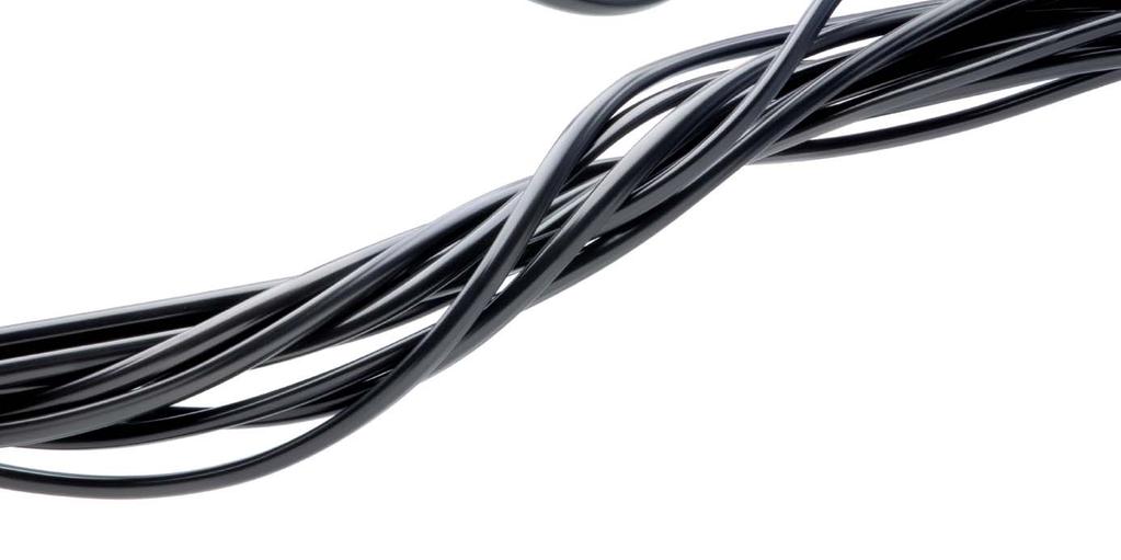
3 Cable glands are regarded as a low priority device and are often the last thing to be considered when purchasing equipment and cables. Cable glands are critical safety devices in the overall electrical system of a plant or installation. The importance of using and selecting the correct cable gland type should not be overlooked. There are various types of cable glands from the simple A type gland right through to the compound barrier gland. This booklet is intended as a guide to the end user (the electrician) to help in understanding the different types of cable glands available and when to select one type of gland rather than another type. Fig 1: Standard industrial cable gland Cable glands are designed to be used on armoured or non-armoured cables. It must be emphasised that it does not matter what type of gland is used or how much it costs, the gland must always be fitted in accordance with the gland manufacturers instructions. 2
4 Legislation Cable glands are designed, manufactured and tested to meet the stringent standards laid down by British, European and international standards. The flow chart shown below shows the standards used in the UK over the last forty years. The European Standard EN for metric cable glands was published in September As a result the previous UK national standard BS 6121 for mechanical cable glands was withdrawn. EN was published in the UK as BS EN in March The latest edition of BS 6121 part 1- mechanical cable glands. Armour glands. Requirements and test methods and part 5 - code of practice for selection, installation and inspection of cable glands and armour glands was published in
5 Cable Types For cable types refer to booklet entitled Cable used in potentially explosive atmospheres. Types of Cable Glands BS 6121 specified requirements for the design and construction of cable glands and gave type designations to glands. The following designations are sometimes used by cable gland manufacturers in their product codes. The basic designations of the glands where as follows: Type A1. For unarmoured cable with an elastomeric or plastic outer sheath, where the function of the gland is to secure the outer sheath of the cable. Type A2. As type A1, but with an IP66 seal between the outer sheath and gland. Type A3. As type A1, but with an electrical bond for the metallic inner sheath. Type A4. As type A2, but with an electrical bond for the metallic inner sheath. Type B. For armoured or wire braid cable, where the function of the gland is to secure the armour or metallic braid and to provide electrical continuity between such armour or braid and the threaded fixing component of the gland. Type C. For armoured or wire braid cable with elastomeric or plastic outer sheath. As type B, but with an IP66 seal between outer sheath and gland. Type D1. For armoured or wire braid cable with elastomeric or plastic outer sheath. As type B, but with an IP66 seal between inner sheath and threaded fixing component. Type D2. As type D1, but with an electrical bond for the metallic inner sheath. Type E1. For armoured or wire braid cable with an extruded elastomeric or plastics inner sheath and elastomeric or plastics outer sheath. As type C, but with an IP66 seal between inner sheath and gland and between the inner sheath and threaded fixing component. Type E2. As type E1, but with an electrical bond for the metallic inner sheath. 4
6 Glands of type B, C, D1, E1 and E2 suitable for armoured or wire braided types of protection shall be identified by a suffix, added to the designation, to indicate the type of protection for which the gland is suitable. The suffix for each type of protection shall be as follows. Single wire armoured Pliable wire armoured flexible Wire braided Aluminium strip armoured Double steel tape armoured W T X Y Z If a gland is suitable for more than one type of protection, all of the relevant suffixes are used. Note: The following is an example of type designations Type CW. A gland for armoured cable with an IP66 seal between outer sheath and gland, for single wire armoured cable. Gland Sizes There are numerous sizes of glands. Refer to cable gland manufacturers literature for full details. Marking All glands shall be marked in accordance with the appropriate standards. An appropriate part of the gland shall be legibly and permanently marked with the following particulars: a) the number of this standard, i.e. BS EN b) the size designation of the gland c) Whenever possible, the type of the gland and the appropriate suffix. 5


7 Construction Cable glands for armoured or braided cables generally have an armour-locking ring refer to figure 2 with the exception of the B type gland. Refer to figure 4. Fig 2: Armoured cable gland The length of the thread on the hub is dependant on the size of the cable gland e.g. a gland size of 20 the hub length is approximately 16mm whilst for a larger cable gland size 90 then the hub thread length is 25mm. Fig 3: Steel wired armoured cable plus gland The armour wires are trapped between a locking ring and the armour cone of the threaded fixing component by the action of screwing the gland body to the hub. 6

8 This ring will continue to trap the armour wires even if the gland body became loose through heat cycling, vibration or during maintenance. The earth continuity can be visually inspected and electrically tested after installation. This is not possible to do with the two-part gland because of the absence of the locking ring. See figure 4. If the gland body is slackened off the earth continuity has gone and there is nothing to inspect. Figure 4: Two Part Gland (C Type) Outdoor cable glands contain either one seal or two seals. As the cable gland is tightened it compresses the seal, which grips the cable. The seals have been tested to IP66 and meet the requirements of the standard. Gland Selection Guide The following list should be used to ensure that the cable gland selected is correct: Select the type of cable and identify the correct gland type Check the type, size and voltage rating of the cable. Check ACTUAL size of cable over the inner sheath. Check ACTUAL size of overall cable diameter. Check the size and type of armour or braiding, if any. Check any special environment conditions including enclosure material in relation to corrosion. Check whether installation is in Hazardous Areas, and consider seal protection for indoor/outdoor use. Check that an entry thread seal is required for IP66 conditions. Check accessories, (i.e. Shrouds, slip on earth tags, locknuts etc). 7
9 IP Rating To maintain IP66 between the equipment and the cable gland, the use of a nylon entry seal is recommended. Refer to section on sealing washers. A threaded joint sealed with a suitable setting compound will maintain IP66. Care should be taken however, to preserve any electrical continuity requirement. With this in mind, glands in conjunction with good quality enclosures (at least 6mm thick) shall maintain an IP rating of IP54 without any additional sealing. Earthing Electrical continuity is normally achieved via the screwed entry into metal boxes. Whenever there is a clearance hole entry situation it is essential to obtain direct metal-to-metal contact between the glands, and therefore an earth tag is used between the gland and the enclosure. For situations where there is a requirement for positive earthing due to high potential currents, the use of armouring alone as the only earthing is not recommended, a range of integral earth glands are available. Insulated adaptors are available for installations where it is necessary to avoid connection between the cable armour/braid and earth at one end of the route, e.g. the break in the earth loop that can otherwise generate spurious signals. Corrosion The standard material used in gland manufacture in the UK is brass; the majority of other countries tend to go for nickel chromium or in special conditions stainless steel. Brass and nickel chromium is suitable for the majority of applications. However, certain environments, notably ammonia and derivatives can cause severe corrosion problem for cable glands. Due to the possibility of bi-metallic corrosion and electrolytic action, especially in moist atmospheres, it is advisable to avoid the contact of dissimilar metals where possible. Brass glands installed in plants or outside areas (moist conditions) should be fitted with brass locknuts. 8


10 Nickel Chromium/Stainless Steel Glands Resistant to alkalis, like caustic and potash; to salt solution and brines, like seawater; to acid gas environments, like those found in the petro-chemical industry. The glands also have good resistance to ammonia solutions; organic acids, like lactic or acetic, like hydrochloric or sulphuric. Gland Types Cable Glands A Type A type glands more commonly known as stuffing glands. There are two types of A gland. A1 and A2, A1 is retained on the cable whilst the A2 gland seals and retains on the cable. Suitable for unarmoured, plastic or rubber sheathed cables. Indoor and outdoor applications. For unarmoured, plastic or rubber sheathed cables. Suitable for most indoor and outdoor applications. Plastic or brass Seal rated to IP66 (A2 version) A1 Cable Gland - A1 cable gland, Plastic only (IP4X) non-certified version only. A2 Cable Gland - A2 cable gland, Plastic and/or brass (IP66) non-certified and certified versions available. 9


11 Cable Glands B Type Suitable for single wire armoured, plastic or rubber sheathed cables. Application - for use in dry, indoor situations only. Brass only IP30 Cable Glands C Type Suitable for cables that are: Plastic or rubber sheathed Extruded or lapped bedded Armoured or braided Outer seal grips sheath of cable Seal rated to IP66 For use in most climatic conditions weatherproof and waterproof. Brass or Stainless steel Design has separate armour locking ring. 10
12 Cable Glands E Type Suitable for cables that are: Plastic or rubber sheathed Extruded or lapped bedded Armoured or braided Outer seal grips sheath of cable Inner seal grips bedding layer of cable Inner and outer seal rated to IP66 For use in most climatic conditions weatherproof and waterproof. Brass or Stainless steel Design has separate armour locking ring. Electrolytic Action There maybe in some cases electrolytic action between two dissimilar metals e.g. gland and enclosure if incompatible materials are selected. This can shorten the lifetime of the gland and the enclosure Gland Kits Advantage: convenient, ready to use. Shrouds For fitting over cable glands where additional protection against onerous weather conditions and corrosion is required. Three types of shrouds available: PCP: used in most hostile conditions and cannot be effected by ultraviolet rays contained in sunlight. PVC: for fast and simple installation. LSF: Low smoke and fume 11
13 Cable gland shrouds can be used where additional protection against environmental conditions is required. Great care should be taken to ensure that the shroud is a snug fit over the cable gland and where necessary the shroud should trimmed to suit the cable diameter. Locknuts There are five types of locknuts available, these are: Mild steel; Stainless steel; Brass; Aluminium; Plastic; Each type has its advantages and disadvantages. Brass locknuts are recommended for most outdoor industrial applications. For corrosive environments, stainless steel locknuts may be the preferred option. Aluminium locknuts should only be used with aluminium glands. Cable glands fitted into clearance hole should be secured by a locking device e.g. locknut, inside the apparatus which is capable of meeting the gland torque requirements. Where a lock nut is the sole means of providing earth continuity to the equipment, it should be brass or mild steel. 12
14 Contacts Technical Peter Roberts Sales Asif Akbar Intertek, Deeside Lane, Chester, Flintshire, CH1 6DD, UK Telephone: +44 (0) About the Author: Peter Roberts Peter started work with the National Coal Board (British Coal) in 1970 as an indentured apprentice electrician. Following a 4-year apprenticeship he worked as a mine craft electrician, and then after further additional studies, became a supervisory electrician and finally qualified as an Electrical Engineer for the mines. In 1987 he moved from the coal mines to the chemical industry and was employed as an Electrical Technician and ultimately becoming the electrical inspector for the 150 Acre site with responsibility for the electrical infrastructure both for the nonhazardous and hazardous areas associated with a top tie COMAH site. Over his many years in the industry, Peter has worked on all types of electrical equipment both hazardous and non-hazardous and on a wide range of voltages from 7.5v dc up to and including volts. After 15 years in the chemical industry he joined Epsilon, which has recently become part of Intertek. He is now one of the Principal Engineers associated with the site services department with responsibility for on-site work at locations throughout the world. Peter is also involved as Lecturer/Trainer/Assessor for the UK s national recognised CompEx Training scheme. For more information on specific testing and certification information, please contact Intertek at WORLDLAB, icenter@intertek.com, or visit our website at Copyright Notice & Disclaimer This publication is copyright Intertek 2009 and may not be reproduced or transmitted in any form in whole or in part without the prior written permission of Intertek. While due care has been taken during the preparation of this document, Intertek cannot be held responsible for the accuracy of the information herein or for any consequence arising from it. Clients are encouraged to seek Intertek s current advice on their specific needs before acting upon any of the content. This booklet is for the exclusive use of Intertek s Client and is provided pursuant to the agreement between Intertek and its Client. Intertek's responsibility and liability are limited to the terms and conditions of the agreement. Intertek assumes no liability to any party, other than to the Client in accordance with the agreement, for any loss, expense or damage occasioned by the use of this information. This booklet may not be reproduced and distributed in whole or part to third parties without the express permission of Intertek 13
TYPE APPROVAL CERTIFICATE
 DET NORSKE VERITAS TYPE APPROVAL CERTIFICATE CERTIFICATE NO. E-12360 This is to certify that the Cable Gland with type designation(s) ADE & RE; AD; FF; MM; SP; ET; LN. Manufactured by COOPER CAPRI SAS
TYPE APPROVAL CERTIFICATE
 TYPE APPROVAL CERTIFICATE Certificate No: TAE000010X File No: 828.90 Job Id: 262.1-010486-4 This is to certify: That the Cable Gland with type designation(s) ADE Issued to COOPER CAPRI SAS (EATON GROUP),
3M Better Buried Closures
 3M Better Buried Closures Instructions March 2016 78-0015-2945-8-A Contents: 1.0 General... 3 2.0 Kit Contents... 3 3.0 Closure Selection Guide... 4 4.0 LHS End Cap Installation... 5 5.0 Cable Preparations...
Optical Distribution Box 300 Installation Guide. Version : R0.0
 Optical Distribution Box 300 Installation Guide Document No. : OD16-546-L-01 Version : R0.0 Date: 21-Mar-2018 IMPORTANT INSTRUCTIONS When using fiber optic equipment, basic precautions should always be
Instrumentation Cables
 Instrumentation Cables 9 KEWBERG manufactures and supplies a wide range of Instrumentation cables, which are made using superior raw materials. These are extensively used in data acquisition systems, process
3M Better Buried Compound Compression Closure System
 3M Better Buried Compound Compression Closure System Instructions March 2016 78-0015-2948-2-A Contents: 1.0 General...3 2.0 Kit Contents...3 3.0 Closure Selection Guide...4 4.0 LHS End Cap Installation...5
AGRO. The Cable Glands.
 AGRO. The Cable Glands. Systems and solutions for industrial applications and electric installations 2 For transportation, a secure grip on the feed line is vital. The Progress cable glands used in railway
IndyGo Facility Upgrades Project 35671EE
 SECTION 260553 IDENTIFICATION FOR ELECTRICAL SYSTEMS PART 1 - GENERAL 1.1 SUMMARY A. Section Includes: 1. Identification for raceways. 2. Identification of power and control cables. 3. Identification for
CONSTRUCTION SPECIFICATION FOR TRAFFIC SIGNAL EQUIPMENT
 ONTARIO PROVINCIAL STANDARD SPECIFICATION METRIC OPSS.PROV 620 APRIL 2017 CONSTRUCTION SPECIFICATION FOR TRAFFIC SIGNAL EQUIPMENT TABLE OF CONTENTS 620.01 SCOPE 620.02 REFERENCES 620.03 DEFINITIONS 620.04
TRANSMISSION ENGINEERING STANDARD TES-P , Rev. 0 TABLE OF CONTENTS 1.0 SCOPE 2.0 CABLES SPLICES
 1.0 SCOPE TABLE OF CONTENTS 2.0 CABLES SPLICES 2.1 Definitions 2.2 Scope of Specifications and Drawings 2.3 General Requirements 2.4 Routing Cables 2.5 Connectors 2.6 Conductor Connections 2.7 Heat Shrinkable
3 Cleaning. 4 Technical data
 EXC+ EXC- Sig- SIG+ SEN- SEN+ 2.4 Attaching cable to the analog board Attaching cable of the weighing cell to the system solution Connect the cable to the appropriate terminal strip of the Ex1 system solution
3M Better Buried Closure (with 3M Scotchlok Shield Bond Connector 4462-FN and 3M High Gel Re-enterable Encapsulant 8882)
") 3M Better Buried Closure (with 3M Scotchlok Shield Bond Connector 4462FN and 3M High Gel Reenterable Encapsulant 8882) Instructions April 2016 78813509979C Contents: 1.0 General... 1 2.0 Kit Contents...
3M Better Buried Closure (with 3M Scotchlok Shield Bond Connector 4462FN and 3M High Gel Reenterable Encapsulant 8882) Instructions April 2016 78813509979C Contents: 1.0 General... 1 2.0 Kit Contents...
3M Distribution Box (DDB)
") 3M Distribution Box (DDB) Merged Copper and Fiber Pole/Post Mount Enclosure Installation Instructions November 2015 78-0015-2736-1-A 2 November 2015 78-0015-2736-1-A Contents 1.0 General 2.0 Enclosure
3M Distribution Box (DDB) Merged Copper and Fiber Pole/Post Mount Enclosure Installation Instructions November 2015 78-0015-2736-1-A 2 November 2015 78-0015-2736-1-A Contents 1.0 General 2.0 Enclosure
e-enterable Fiber Optic Splice Closure (Re-Enterable Aerial Closure for Access Service)
") R e-enterable Fiber Optic Splice Closure (Re-Enterable Aerial Closure for Access Service) Optical Fiber Drop wire Closure Model FOC-CB1612-24DW. Available with optical fiber cable from 12 up to 24 fibers
R e-enterable Fiber Optic Splice Closure (Re-Enterable Aerial Closure for Access Service) Optical Fiber Drop wire Closure Model FOC-CB1612-24DW. Available with optical fiber cable from 12 up to 24 fibers
WARNING VGTWC VGF-1. Model No. Galvanized Steel Thimble and Wire Rope Cable Termination Kit
 VGTWC WARNING All persons using this equipment must read, understand and follow all instructions. In addition, all instructions provided with the cable and/or lifeline system with which this equipment
3 Foam Sealed Closure 2" (50 mm) with Compound Compression
 with Compound Compression") 3 Foam Sealed Closure 2" (50 mm) with Compound Compression Instructions 1.0 General 1.1 The 3M Foam Sealed Closure is designed to be used in the construction and maintenance of buried and underground PIC
3 Foam Sealed Closure 2" (50 mm) with Compound Compression Instructions 1.0 General 1.1 The 3M Foam Sealed Closure is designed to be used in the construction and maintenance of buried and underground PIC
EMC cable glands. AGRO cable glands for interference-free cable installations.
 EMC cable glands. AGRO cable glands for interference-free cable installations. EMC. A topic with serious consequences. Electromagnetic compatibility (EMC) is something that everyone in our modern world
Trusted TMR I/O SmartSlot Slot Cables
 PD-TC500 Trusted Trusted TMR I/O SmartSlot Slot Cables Product Overview This document provides detailed information for the types of Trusted input/output (I/O) Cables available within the SmartSlot group.
Cambria County Association for the Blind and Handicapped 175 Industrial Park Road Ebensburg, PA Prepared for: Prepared by:
 Cable Management in Solar PV Arrays: A Review of Requirements in the National Electrical Code and how CAB Cable Rings and Saddles Meet These Requirements Prepared for: Cambria County Association for the
7 Lighting Technology
 7 Lighting Technology Floodlight 09676E00 explosion protected floodlight for use in explosive gas atmospheres of Zone 2 as well as in areas with combustibledust of Zone 21 and Zone 22. Explosion protection
Gel-sealed in-line fiber optic closure
 SCIL-C Gel donut INSTALLATION INSTRUCTION TC-1363-1-IP Rev A, Oct 2017 www.commscope.com Gel-sealed in-line fiber optic closure Contents 1 General 2 Sizing and product kit information 3 Installation conditions
Contents. Track Circuit Rail Connection Components. Yellow Bonding Kits and T.P.W.S Joint and Termination Kits
 Contents Page 1 Gas Torch Kits for use with Heatshrink materials Page 2 Track Circuit Rail Connection Components Page 3 Track Circuit Rail Connection Kits Page 4 Track Circuit Cable Joint Kits Page 5 Duplicated
 www.mete-enerji.com.tr INDUSTIAL IEC PLUGS AND SOCKETS INDUSTIAL IEC PLUGS AND SOCKETS Position of the Earthing Contact acc. to IEC 60309-2 225/400-265/460 V~ 60 Hz (1) 3 P+N+ 3 P+ 2 P+ 120/208-144/250V~
Fiber Optic Splice Closure GPJ Instruction Manual
 Fiber Optic Splice Closure GPJ09-9401 Instruction Manual 1. Brief Introduction GPJ09-9401 type of Fiber Optic Splice Closure is a member in dome series, the main function is to provice direct pass, branch
XS_-EU. M8 and M12 Sensor Connectors. Ordering Information
 M8 and M Sensor Connectors XS_-EU For a wide range of applications the XS_-EU family of M8 and M sensor connectors provides the high performance and features making the family the ideal choice for standard
SPECIFICATION FIBER OPTIC SPLICE CLOSURE. Spec No : VSS-1007-BS403A-04A/SD. VSS-0107-BS403A-04A/SD R & D Center Manufacturing Division
 SPECIFICATION FIBER OPTIC SPLICE CLOSURE Model Spec. No. Distribution Depts. VSOF-BS403A VSS-0107-BS403A-04A/SD R & D Center Manufacturing Division Sales Division Management Division Revision 10. 07 (Rev.4)
Instructions. Cable with Armor F CAUTION. October Rev A
 3M Single Conductor Accessory Breakout Kits (BOK's) for use with 3M Cable Accessories (Terminations, T-Bodies and Push-On Elbows) For Use With Single Conductor Accessories On Three-Core Conductor Cables
Flexible Cord. Inside this section
 2 Strain Relief Cord Connectors provide a liquid tight and strain relief termination for flexible type neoprene, vinyl, or PVC control cord and cable, and are now offered in steel, aluminum, and nylon.
EXEL. Ex de. - Double locking system operated by hexagonal-head tool - Double channel electronic ballast - Zones 1, 2, 21, 22. G13 bi-pin lamp holder
 EXEL - Double locking system operated by hexagonal-head tool - Double channel electronic ballast - Zones 1, 2, 21, 22 Reinforced polyester resin body G13 bi-pin lamp holder Internal emergency batteries
2179-CD Series Fiber Optic Splice Closure. Installation Instructions
 2179-CD Series Fiber Optic Splice Closure Installation Instructions 1.0 Product Introduction The new 3M TM 2179-CD Series Fiber Optic Splice Closure can be used in buried, underground, aerial, and pedestal
VITALink Taped Splice Straight Through Crimp
 A Marmon Wire & Cable Berkshire Hathaway Company VITALink Taped Splice Straight Through Crimp 2 Hour Fire-Rated Splice VITALink MC Cables, UL FHIT 120 Installation Instructions Description The VITALink
Explosion Proof Audible Signal db(a) Series YA60
 Series YA60") > Omnidirectional high output sounder 110 db (A) / 1 m > 2 stage alarm, independently selectable 2nd stage > IP66 rated as standard > Aluminium enclosure with stainless steel fasteners > 32 selectable
> Omnidirectional high output sounder 110 db (A) / 1 m > 2 stage alarm, independently selectable 2nd stage > IP66 rated as standard > Aluminium enclosure with stainless steel fasteners > 32 selectable
Installation instructions Cable transit device Roxtec RS ES Ex
 General information Installation and maintenance: For European member countries of GENELEC, shall standard EN 60079-14 and EN 60079-17 be considered. For countries members of IECEx shall standard IEC 60079-14
EXPlora. Introduction
 Introduction EXPlora The EXPlora range is most suited to manufacturers of ancillary electrical equipment such as motors, pumps, lighting equipment, process and control gear for use in factories and plant
Quick Term III. 3M Cold Shrink 3 Core Indoor Termination. 3.3 kv mm 2
 Quick Term III 3M Cold Shrink 3 Core Indoor Termination Instruction Sheet All dimensions shown are mm unless otherwise stated Kit Contents 3 QT-III Termination Assembly 1 Cold Shrink Breakout Boot 3 Phase
HN Connectors. Automatic Connector. Introduction. Contents. 631/ FAX 631/
 Connectors Introduction 2004 Automatic Connector. All rights reserved. pdf 1.0 4-13-04 Contents Specifications........................... 2 Straight Cable Plugs...................... 3 Right Angle Cable
3 SLiC Aerial Closure with Rubber End Seal
 3 Aerial Closure with Rubber End Seal Instructions 1.0 General 1.1 This instruction bulletin describes the assembly of the 3M Aerial Closure with external bonding hanger brackets. These closures are suitable
FOSC-600 C and D I N S T A L L A T I O N I N S T R U C T I O N
 FOSC-600 C and D I N S T A L L A T I O N I N S T R U C T I O N In-line and butt version Cold applied re-usable fiber optic closure Contents 1 Introduction 1.1 Product description 1.2 Capacity 2 General
High Performance TOR-SPRING EMI/RFI Cord Grips
 High Performance TOR-SPRING EMI/RFI Cord Grips The Importance of Meeting EMC Requirements When specifying and designing today s electronic control and data acquisition systems, consideration must be given
IEC Standard for Luminaires Part 1: General Requirements and Tests, IEC Edition 8, Issued May The
 3933 US Route 11 Cortland, NY. 13045 Telephone: 607-758-6711 www.intertek-etlsemko.com February 27, 2015 Heilux LLC Walter Paciorek 10200 Valley View Suite 100 Eden Prarie,MN 55344 Intertek Test Report:
NC-1000 INSTALLATION MANUAL NC-1000 FIBRE OPTIC CROSS-CONNECTION SYSTEM
 NC-1000 INSTALLATION MANUAL NC-1000 FIBRE OPTIC CROSS-CONNECTION SYSTEM Content 1. General 5 2. The products of NC-1000 system 6 3. Mounting of the frame 8 4. Earthing of the frame 8 NC-1000 FIBRE OPTIC
DOME OPTIC SPLICE CLOSURE
 FIBER OPTIC SPIICE CLOSURE GJS-JKDH1001-120 BOX DIMENSION: W=140mm H=340mm Weight = 1.80 kgs Outer Internal structure Fuse fiber disc Type sealing ring Plastic hoop base Pole Mount Pole Mount 1 1. product
FIST-MB2-S. FIST Medium Box for Cable Splicing Only. 4 Cable installation. 1 Introduction. Contents. 2 General. 5. Fiber routing to individual trays
 FIST-MB2-S I N S T A L L A T I O N I N S T R U C T I O N FIST Medium Box for Cable Splicing Only Contents 1 Introduction 1.1 Product description 2 General 2.1 Tools 2.2 Kit contents 3 Installation and
Automatic Connector MHV Connectors MHV Introduction MHV series connectors Contents Polarized mating interfaces Anti-Rock mating interfaces
 Automatic s 2004 Automatic. All rights reserved. pdf 1.0 3-18-04 Contents Specifications........................... 2 Straight Cable Plugs...................... 3 Right Angle Cable Plugs...................
2178-L/S Series Fiber Optic Splice Case with Gasket
 2178-L/S Series Fiber Optic Splice Case with Gasket Instructions for: 2178-S Splice Case 2178-LS Splice Case 2178-LL Splice Case 2181-LS Cable Addition Kit May 1997 34-7041-9949-5-A 1 Table of Contents
PT9420 Cable Actuated Sensor Industrial ma 0..20mA
 PT9 Cable ctuated Sensor Industrial.. m 0..m bsolute Linear Position to 550 inches ( meters) luminum or Stainless Steel Enclosure Options VLS Option to Prevent Free-Release Damage IP68 / NEM 6 Hazardous
Guide for installers. METTLER TOLEDO MultiRange System solution analog Ex1. Hazardous area. Safe area
 Guide for installers METTLER TOLEDO MultiRange System solution analog Ex1 Hazardous area Safe area System solution analog Ex1 Contents Contents Page 1 Safety precautions... 2 2 System overview... 3 2.1
NORTHWESTERN UNIVERSITY PROJECT NAME JOB # ISSUED: 03/29/2017
 SECTION 26 0553 - IDENTIFICATION FOR ELECTRICAL SYSTEMS PART 1 - GENERAL 1.1 RELATED DOCUMENTS A. Drawings and general provisions of the Contract, including General and Supplementary Conditions and Division
3.3. Ex-Escape sign luminaires. Ex-Lite Metal version with LED technology for Zone 1 and Zone 21 / NEC applications
 . Ex-Escape sign luminaires Ex-Lite Metal version with LED technology for Zone 1 and Zone 21 / NEC applications The robust escape sign luminaire The Ex-Lite series of explosion-protected escape sign luminaire
PEM1126ENG ENGLISH STPKR. TERMINATION KIT FOR PAPER CABLE WITH LEAD SHEATH 1 kv INSTALLATION INSTRUCTION
 INSTALLATION INSTRUCTION PEM1126ENG 2010-05 TERMINATION KIT FOR PAPER CABLE WITH LEAD SHEATH 1 kv ENGLISH 2/6 PEM1126ENG 2010-05 GENERAL INFORMATION - Check that the kit is suitable for the cable type.
Installation instructions Roxtec RS ES Ex
 General information Installation and maintenance: For European member countries of GENELEC, shall standard EN 60079-14 and EN 60079-17 be considered. For countries members of IECEx shall standard IEC 60079-14
Amphenol. Amphenol-Tuchel Electronics GmbH. C 112 Series M12 - Connectors
 Amphenol Amphenol-Tuchel Electronics GmbH C 112 Series M12 - Connectors We connect con The company Amphenol-Tuchel Electronics is a worldwide leader in electrical connectors and contacting devices. Our
Scotch Heavy Duty Vinyl Electrical Tape 22
 Scotch Heavy Duty Vinyl Electrical Tape 22 Data Sheet July 2015 Description Agency Approvals & Self Certifications Scotch Heavy Duty Vinyl Electrical Tape 22 is a premium grade, 10-mil thick, vinyl insulating
18W Low Energy Dusk-Dawn Bulkhead E-290B
 18W Low Energy Dusk-Dawn Bulkhead E-290B INSTALLER GUIDE V1.0-12/06 IQ-ABH01-PH-18-PR IQ Europe Limited Sandbeck Lane, Wetherby LS22 7TW. Visit us at www.iq-europe.co.uk Installation helpline 0871 717
LEGEND POWER SYSTEMS
 S HEAT SHRINK JOINT 11kV 3 CORE Armoured XLPE/EPR Copper Wire screens STRAIGHT JOINT LEGEND POWER SYSTEMS Date 11 November 2014 Instruction Number PJJ006-14C PJJ006-14C Page 1 of 10 HEAT SHRINKABLE JOINT
Catalog. Industrial Plugs & Sockets The complete range
 Catalog Industrial Plugs & Sockets The complete range Contents Type Page Introduction... 4 IEC 60309-2 (clock)... 5 Product overview Critical & Safe... 6 Tough & Safe... 7 Easy & Safe... 8 Plugs Splashproof...
FOSC 450 C6 and D6 Closures
 FOSC 450 C6 and D6 Closures I N S T A L L A T I O N I N S T R U C T I O N Fiber Optic Splice Closure 1. General Product Information The FOSC 450 C6 and D6 fiber optic splice closures use compressed gel
Guide for installers. METTLER TOLEDO MultiRange System solution Point Ex.
 Guide for installers METTLER TOLEDO MultiRange System solution Point Ex www.mt.com/support System solution Point Ex Contents Contents Page 1 Safety precautions... 4 2 System overview... 5 2.1 Using the
Medium Box for Cable Termination
 FIST-MB2-T I N S T A L L A T I O N I N S T R U C T I O N Medium Box for Cable Termination Contents 1 Introduction 1.1 Product description. 2 General 2.1 Tools 2.2 Kit contents 3 Installation and pre assembling
Installation Instructions
 TECP-30-260 Issue 2 July 2016 Installation Instructions OWB-S OWB-S Small Wall-mounted Box CONTENTS 1. Introduction 2. Kit content 3. Installation Instruction 3.1. Box installation 3.2. Conduit installation
IECEx International Conference 2017 Shanghai, China. Electrical Installations Design, Selection, Erection and Inspection Part 2 of 2
 IECEx International Conference 2017 Shanghai, China Electrical Installations Design, Selection, Erection and Inspection Part 2 of 2 10. Cable entry systems and blanking elements 10.2 Selection of cable
Installation Manual for New or Retrofit Installations
 Installation Manual for New or Retrofit Installations Release Date: 24-August-2015 c Able Applied Technologies LTD. READ THE ENTIRE MANUAL COMPLETELY AND CAREFULLY BEFORE STARTING BEFORE YOU BEGIN ASSEMBLY
Safety dialogue solutions
 Characteristics 5 Environment Conformity to standards Products XY2 CH, XY2 CE: EN/IEC 60947-5-1, EN/ISO 13850:2006, UL 508 and CSA C 22-2 n 14 (with suffi x H7) XY2 CB: EN/IEC 60947-5-1, EN/ISO 13850:2006,
FLEXIBLE CONDUIT AND ACCESSORIES
 CABLE PROTECTION AND EQUIPMENT FLEXIBLE CONDUIT AND ACCESSORIES Kabelflex Protecting underground buried electrical & telecommunication cables: Kabelflex is a cable conduit (duct) used for protecting underground
Bharat Heavy Electricals Limited HIGH PRESSURE BOILER PLANT, TIRUCHIRAPPALLI CONTROLS AND INSTRUMENTATION/FB
 Bharat Heavy Electricals Limited HIGH PRESSURE BOILER PLANT, TIRUCHIRAPPALLI 620 014. CONTROLS AND INSTRUMENTATION/FB DATA SHEET FOR MULTICORE, ARMOURED, CONTROL CABLE Project: Ennore Sez, 2 x 660 MW,
Installation instructions Ex frames
 General information Installation and maintenance: For European member countries of GENELEC shall standard EN 60079-14 and EN 60079-17 be considered. For countries members of IECEx shall standard IEC 60079-14
Pendant Light Fitting IEC Series 6470/2
 > Available light sources high-pressure sodium lamps (HSE) metal halide lamps (HIE) halogen lamps (QT) > Versatile mounting methods > Enclosure made of saltwater-resistant aluminium www.stahl.de 11435E
INSTRUCTION AND MAINTENANCE VIDEO MOTORE PROJECTION SCREEN
 INSTRUCTION AND MAINTENANCE VIDEO MOTORE PROJECTION SCREEN 1.1 TECHNICAL DATA PRODUCT DESCRIPTION Screens made with the following projection fabrics: SOFT WHITE, MATT WHITE SOFT, SOFT WHITE TRANSOUND,
Instruction Manual MODEL RSP SANITARY ELECTRONIC PRESSURE TRANSMITTER
 Instruction Manual Anderson Instrument Co. Inc. 156 Auriesville Road Fultonville, NY 12072 1-800-833-0081 Fax 518-922-8997 www.andinst.com Instrument Model Number Instrument Serial Number MODEL RSP SANITARY
OPERATION AND MAINTENANCE MANUAL
 OPERATION AND MAINTENANCE MANUAL SERIAL NUMBER CUSTOMER: SALES REP.: CONTENTS Mixer Installation / Assembly / Dimension Drawings Safety... 1 Customer Service Contact... 1 Initial Inspection... 2 Installation...2
DMP 335 DMP 335. Industrial Pressure Transmitter. Welded, Dry Stainless Steel Sensor. Pressure Transmitter. Industrial
 DMP 5 Industrial Pressure Transmitter Welded, Dry Stainless Steel Sensor accuracy according to IEC 60770: 0.5 % FSO Industrial Pressure Transmitter Nominal pressure from 0... 6 bar up to 0... 600 bar Output
3M Super 23 Electrical Tape
 WEATHERPROOFING S CHEMICALS ET 3M SUPER 23 Features: Premium all-weather black electrical tape Remains conformable at -18 C /0 F 7mm thickness UV resistant Part # Size ET 3M Super 23 19mm x 9.15m WEATHERPROOFING
PEM1124ENG ENGLISH. STK TERMINATION KIT FOR PLASTIC CABLE WITHOUT ARMOURING 1 kv STKR TERMINATION KIT FOR PLASTIC CABLE WITH ARMOURING 1 kv
 INSTALLATION INSTRUCTION PEM1124ENG 2010-05 STK TERMINATION KIT FOR PLASTIC CABLE WITHOUT ARMOURING 1 kv STKR TERMINATION KIT FOR PLASTIC CABLE WITH ARMOURING 1 kv ENGLISH 4 CORE 3+1 CORE 2/8 PEM1124ENG
Cable installation guidelines
 The Quality Connection Cable installation guidelines Business Unit Industrial Projects 2 Cable installation guidelines www.leoni-industrial-projects.com GENERAL Installation methods Many different methods
SBN Pendant Pushbutton Station. Instruction Manual. Part Number: R1 January 2016 Copyright 2016 Magnetek Material Handling
 SBN Pendant Pushbutton Station Instruction Manual Part Number: 126-11173 R1 Copyright 2016 Magnetek Material Handling Table of Contents Service Contact Information... 3 Preface and Safety... 4 Product
Eddy Current Probe System
 CMSS 785 Eddy Current Probe System API-670 Proximity transducer system, 5 mm and 8 mm Eddy Current Probe System The CMSS 785 system is an eddy current type non-contact displacement/ vibration system, used
KEL 183 Cable entry frames
 KEL 183 Cable entry frames Description Type Order.No. Inserts KT PU KT 183 KT large The new version of the split cable entry frame KEL 183 enables the user to route cables and tubes with a diameter up
ELECTRICAL SAFETY INSPECTION REPORT
 ELECTRICAL SAFETY INSPECTION REPORT A PLUS INDUSTRIES LIMITED. Plot-28, Milk Vita Rd., Section-07, Mirpur, Dhaka Factory List: 1. A Plus Industries Ltd. Inspected by: Yoon Report Generated by: Nezar Inspected
DMP 335. Industrial Pressure Transmitter. Welded, Dry Stainless Steel Sensor. accuracy according to IEC 60770: 0.5 % FSO.
 DMP 5 Industrial Pressure Transmitter Welded, Dry Stainless Steel Sensor accuracy according to IEC 60770: 0.5 % FSO Nominal pressure from 0... 6 bar up to 0... 600 bar Output signals -wire: 4... 0 ma -wire:
S020 fluorescent tube luminary
 S020 fluorescent tube luminary DESCRIPTION: Fluorescent lamps S020 are suitable above all for uniform lighting of bigger areas. Lamps from the range S020 are manufactured from extruded aluminium profile
18mm ECAM Cable Entry Port
 18mm ECAM Cable Entry Port Instructions October 2006 1.0 Introduction The 3M 18mm ECAM (External Cable Assembly Module) Cable Entry Port Kit is designed to accept fiber optic cables with external diameters
KVT Split cable glands
 KVT Description Type Order Grommets Thread PU KVT is a circular split frame for quick and easy installation and sealing of cables with connectors or complete cable harnesses. 3 KVT 20** 34 24 M20. Polyamide
Signalling Cable Equivalent Sizes
 Signalling Cable Equivalent Sizes Signatures removed from electronic version Submitted by... Jim Harper Nominated Responsible Manager Synopsis This Standard Authorises the use of cables to GS/ES 0872 as
TECHNICAL MANUAL DRAW-WIRE DISPLACEMENT TRANSDUCER TYPE DWT
 RDP Customer Document TECHNICAL MANUAL DRAW-WIRE DISPLACEMENT TRANSDUCER TYPE DWT Doc. Ref CD1004L BS EN ISO 9001 Certificate No. FM13141 Affirmed by Declaration of Conformity USA & Canada RDP Electrosense
Trends and Challenges of HV Cable Systems
 Trends and Challenges of HV Cable Systems Bruno Arnold Electrical Engineer FH Global Sales Far East, Latin America and India Pfisterer Business Unit PTS Cable Trends and Challenges of HV Cable Systems
TERMINATIONS AND JOINTS FOR XLPE-INSULATED kv MEDIUM VOLTAGE CABLES
 Accessories TERMINATIONS AND JOINTS FOR XLPE-INSULATED 12 36 kv MEDIUM VOLTAGE CABLES Cable Systems, Cables and Accessories Test values for terminations 1) Testing to DIN VDE 0278-629-1 (Testing methods
2178 Fiber Optic Splice Case and 2181 Cable Addition Kit
 2178 Fiber Optic Splice Case and 2181 Cable Addition Kit Instructions January 1994 Issue 1, 34-7029-6387-6 1 2 Contents: 1.0 General... 4 2.0 Specifications... 4 3.0 Kit Contents... 5 SECTION 1: 2178 Splice
Explosion Proof Audible Signal db(a) Series YA60
 Series YA60") > Omnidirectional high output sounder 110 db (A) / 1 m > 2 stage alarm, independently selectable 2nd stage > IP66 rated as standard > Aluminium enclosure with stainless steel fasteners > 32 selectable
> Omnidirectional high output sounder 110 db (A) / 1 m > 2 stage alarm, independently selectable 2nd stage > IP66 rated as standard > Aluminium enclosure with stainless steel fasteners > 32 selectable
TECHNICAL SPECIFICATION
 TECHNICAL SPECIFICATION (FIBER OPTIC SPLICE CLOSURE) Model Spec. No. Distribution Depts. VSOF-BS403A SJP-0609-403A-01A/SD Quality Assurance Team Manufacturing Division Sales Division Management Division
PERFORMANCE SPECIFICATION SHEET CONNECTORS, PLUGS, ELECTRICAL, COAXIAL, RADIO FREQUENCY (SERIES SMA (CABLED) - PLUG, PIN CONTACT, CLASS 2)
 - PLUG, PIN CONTACT, CLASS 2)") INCH-POUND MIL-PRF-39012/55G 6 February 2008 SUPERSEDING MIL-PRF-39012/55G 6 January 2006 PERFORMANCE SPECIFICATION SHEET CONNECTORS, PLUGS, ELECTRICAL, COAXIAL, RADIO FREQUENCY (SERIES SMA (CABLED) -
INCH-POUND MIL-PRF-39012/55G 6 February 2008 SUPERSEDING MIL-PRF-39012/55G 6 January 2006 PERFORMANCE SPECIFICATION SHEET CONNECTORS, PLUGS, ELECTRICAL, COAXIAL, RADIO FREQUENCY (SERIES SMA (CABLED) -
LINK-RAY TM MODULATORS FOR CONSTANT- VOLTAGE. LinkRay Modulators 12 V / 24 V Constant-voltage Applications MODULATORS
 MUSIUM RESTAURANT SOUVENIR SHOP EXIT LinkRay Modulators 12 V / 24 V Constant-voltage Applications LINK-RAY TM MODULATORS FOR CONSTANT- VOLTAGE LINK-RAY TM MODULATORS FOR CONSTANT-VOLTAGE APPLICATIONS 186755
3M Fiber Optic Splice Closure 2178-XL & 2178-XL/FR
 3M Fiber Optic Splice Closure 2178-XL & 2178-XL/FR 3M Cable Addition Kit 2181-XL and 2181-XL/FR Instructions September 2017 78-8130-5055-2-M 2 September 2017 78-8130-5055-2-M 1.0 Kit Contents 2.0 General...
3M Fiber Optic Splice Closure 2178-XL & 2178-XL/FR 3M Cable Addition Kit 2181-XL and 2181-XL/FR
 3M Fiber Optic Splice Closure 2178-XL & 2178-XL/FR 3M Cable Addition Kit 2181-XL and 2181-XL/FR Instructions July 2010 3 1.0 Contents 1.0 General...3 2.0 Kit Contents...3 3.0 Cable Preparation...4 4.0
ECONOMICAL 36 kv CABLE SYSTEM FOR THE BELGIAN NETWORK
 ECONOMICAL 36 kv CABLE SYSTEM FOR THE BELGIAN NETWORK J. Becker NEXANS BENELUX S.A. F. Musique ELECTRABEL S.A. ABSTRACT In order to tackle the deregulated market with confidence and in a realistic way,
AMERICAN NATIONAL STANDARD
 ENGINEERING COMMITTEE Interface Practices Subcommittee AMERICAN NATIONAL STANDARD ANSI/SCTE 153 2008 Drop Passives: Splitters, Couplers and Power Inserters NOTICE The Society of Cable Telecommunications
KVT Split cable glands
 KVT Split cable glands Description Type Order Inserts KT Thread PU No. small large Thread length KVT is a circular split frame for quick and easy installation of cables or complete cable harnesses. Polyamide
STANDARD FOR MULTI-DWELLING UNIT (MDU) OPTICAL FIBER CABLE. Publication S First Edition - June 2012
 OPTICAL FIBER CABLE. Publication S First Edition - June 2012") STANDARD FOR MULTI-DWELLING UNIT (MDU) OPTICAL FIBER CABLE Publication S-115-730 First Edition - June 2012 Published By Insulated Cable Engineers Association, Inc. Post Office Box 1568 Carrollton, Ga 30112,
STANDARD FOR MULTI-DWELLING UNIT (MDU) OPTICAL FIBER CABLE Publication S-115-730 First Edition - June 2012 Published By Insulated Cable Engineers Association, Inc. Post Office Box 1568 Carrollton, Ga 30112,
Installation instructions Roxtec RM ES B
 Installation instructions Roxtec RM ES B Environmental side Termination/ interior side Pipe Cable screen/armor Layers Termination/ interior side Cable sheath Layers Environmental side Vertical screen Plastic
PERFORMANCE SPECIFICATION SHEET CONNECTORS, PLUGS, ELECTRICAL, COAXIAL RADIO FREQUENCY, (SERIES TNC (CABLED), PIN CONTACT, RIGHT ANGLE, CLASS 2)
, PIN CONTACT, RIGHT ANGLE, CLASS 2)") INCH-POUND MIL-PRF-39012/30H 15 March 2018 SUPERSEDING MIL-PRF-39012/30H w/amendment 3 15 April 2017 PERFORMANCE SPECIFICATION SHEET CONNECTORS, PLUGS, ELECTRICAL, COAXIAL RADIO FREQUENCY, (SERIES TNC
INCH-POUND MIL-PRF-39012/30H 15 March 2018 SUPERSEDING MIL-PRF-39012/30H w/amendment 3 15 April 2017 PERFORMANCE SPECIFICATION SHEET CONNECTORS, PLUGS, ELECTRICAL, COAXIAL RADIO FREQUENCY, (SERIES TNC
Inductive sensor NI3-EG08K-Y1-H1341
 ATEX category II 1 G, Ex zone 0 ATEX category II 1 D, Ex zone 20 SIL2 (Low Demand Mode) acc. to IEC 61508, PL c acc. to ISO 13849-1 at HFT0 SIL3 (All Demand Mode) acc. to IEC 61508, PL e acc. to ISO 13849-1