RF/Microwave Connectors & Cable Assemblies
|
|
|
- Albert Nichols
- 6 years ago
- Views:
Transcription


1 RF/Microwave Connectors & Cable Assemblies Emerson Network Power Connectivity Solutions
2 Connectivity Solutions To our valued customers: For over 80 years, Johnson Components and Cambridge Products have been providing our electronics distributor and OEM customers with cost-effective, high-quality solutions for connectivity. This catalog combines the product lines of Johnson Components and Cambridge Products under the Johnson product line of Emerson Network Power Connectivity Solutions. In addition to combining these product lines, we have also combined several of our interconnect businesses under the name Emerson Network Power Connectivity Solutions. We believe this name not only reflects our traditional industry focus, but also better communicates the additional resources that we can supply as part of Emerson Network Power. Although our name is changing, our commitment to product quality and to excellent service to our customers will not. Our combined connectivity product line will continue to focus on the wireless, test/measurement, instrumentation, OEM and installer markets for data networks, telecommunications, satellite, security, telemetry and CATV. This catalog offers our customers new products such as the SMK (2.92mm) range of 40 GHz connectors and non-magnetic connectors for the medical industry as well as extensive enhancements to our existing product portfolio. It continues to provide comprehensive data on our range of coaxial connectors, cable assemblies, hardware, tools and test products to support your design and application needs and those of your customers. Emerson Network Power Connectivity Solutions is a global player with manufacturing, sales and engineering presence in China, the United Kingdom and the United States to meet our customers requirements around the world. Our goal is to continue to expand our product offerings and capabilities to continue meeting your changing needs. Thank you for allowing us the opportunity to serve you. Best Regards, Brian G. Mason President Emerson Network Power Connectivity Solutions
3 MMCX Connectors Alphabetical Index MMCX Connectors - 50 Ohm PC Mount... 7 Specifications... 4 Semi-Rigid and Flexible Cable... 5 Termination... 8 Other Information Assembly Instructions Assembly Tools Cable Assembly Cable Information Capabilities Mounting Hole Layouts Numerical Index Ordering Information... 2 Competitor Cross Reference Connectivity Solutions Tel: Fax:
4 MMCX - 50 Ohm Connectors Specifications ELECTRICAL RATINGS Impedance: 50 ohms Frequency Range: Connectors GHz Dummy loads GHz VSWR: (f = GHz) Straight Right Angle Cabled Connectors Cabled Connectors.047 dia flexible f RG-178, RG-316, RG-316 DS Semi-Rigid Uncabled receptacles, dummy loads... N/A Working Voltage: Connectors VRMS at sea level Dummy loads... N/A Dielectric Withstanding Voltage: Connectors VRMS at sea level Dummy loads... N/A Insulation Resistance: 1000 megohms min Contact Resistance: (milliohms maximum) After Initial Environmental Center contact (straight cabled connectors and uncabled receptacles) Center contact (right angle cabled connectors) Outer contact (all connectors) Braid to body N/A Corona Level: Connectors volts min at 70,000 feet Dummy loads... N/A Insertion Loss: (db max tested at 1 GHz) Straight cabled connectors Right angle cabled connectors Uncabled receptacles, dummy loads... N/A RF Leakage: (db minimum, tested at 2.5 GHz) Flexible cable connectors db.086 Semi-Rigid db Dummy loads... N/A RF High Potential Withstanding Voltage: (400 VRMS at 4 and 7 MHz) Power Rating (Dummy Load): C, derated to C Avoid user injury due to misapplication. See safety advisory definitions inside front cover. MECHANICAL RATINGS Engagement Design: Series MMCX Engagement/Disengagement Force: 8 lbs. max axial engagement 1.4 lbs. min axial disengagement Contact Retention: 2.0 lbs. minimum axial force Cable Retention: Axial Force* (lbs.) Torque (in-oz) Connectors for.047 flexible 3.5 N/A Connectors for RG N/A Connectors for RG N/A Connectors for RG-316 DS N/A Connectors for.086 Semi-Rigid *Or cable breaking strength whichever is less. Durability: cycles minimum ENVIRONMENTAL RATINGS (Meets or exceeds the applicable paragraph of MIL-C-39012) Operating Temperature: Connectors C to C Dummy loads C to C Thermal Shock: Connectors: MIL-STD-202, Method 107, Condition C, except -55 C to C (N/A dummy loads) Corrosion: MIL-STD-202, Method 101, Condition B (N/A dummy loads) Shock: MIL-STD-202, Method 213, Condition B (N/A dummy loads) Vibration: MIL-STD-202, Method 204, Condition D (N/A dummy loads) Moisture Resistance: MIL-STD-202, Method 106 (N/A dummy loads) MATERIAL SPECIFICATIONS Bodies: Brass per QQ-B-626, gold plated* per MIL-G " min. Contacts: Beryllium copper per QQ-C-530, gold plated* per MIL-G " min. Interface Spring: Beryllium copper per QQ-C-530, gold plated* per MIL-G " min. Insulators: PTFE fluorocarbon per ASTM D 1710 and ASTM D 1457 Crimp Sleeves: Copper per WW-T-799 or brass per QQ-B-626, gold plated per MIL-G " min. Mounting Hardware: Brass per QQ-B-626 or QQ-B-613, gold plated per MIL-G " min. *All gold plated parts include a min nickel barrier layer. JACK PLUG JACK REFERENCE PLANE PLUG Mating Engagement for MMCX Series 1. ID of contact to meet VSWR mating characteristics and connector durability when mated with a dia.016 +/-.001 male contact. 2. Must meet the force to engage and disengage when mated with mating part. 4 Connectivity Solutions Tel: Fax:

 Crimp Insert Axon P512479A Astrolab 32018 DS RG-178/U, 196 135-3402-101.354 (8.99).276 (6.")
.334 (8.48) Crimp Sleeve Assembly instructions pages 208 and 209.")
5 MMCX - 50 Ohm Connectors For Semi-Rigid and Flexible Cable Right Angle Solder Type Plug - Captivated Contact CABLE TYPE PART NO..086 Semi-Rigid Assembly instructions page 207. Right Angle Crimp Type Plug - Captivated Contact CABLE TYPE PART NO. A B TERMINATION.047" Diameter Flexible Huber K (8.99).276 (6.98) Crimp Insert Axon P512479A Astrolab DS RG-178/U, (8.99).276 (6.98) Crimp Insert RG-178/U, (10.46).334 (8.48) Crimp Sleeve RG-316/U, 188, (10.46).334 (8.48) Crimp Sleeve 179, 161, 174 RG-316 DS, RG-188 DS (10.46).334 (8.48) Crimp Sleeve Assembly instructions pages 208 and 209. Connectivity Solutions Tel: Fax:
.137 (3.48) Crimp Insert Axon P512479A Astrolab 32018 DS RG-178/U, 196 135-3402-001.462 (11.73).137 (3.48) Crimp Insert RG-316/U, 188, 161, 174 135-3403-001.")
.137 (3.48) Crimp Insert Huber K01152-07 Axon P512479A Astrolab 32018 DS RG-178/U, 196 135-3302-001.462 (11.73).137 (3.48) Crimp Insert RG-316/U, 188,161, 174 135-3303-001.")

6 MMCX - 50 Ohm Connectors For Flexible Cable Straight Crimp Type Plug - Solder or Crimp Captivated Contact Assembly instructions pages 210 and 211. CABLE TYPE PART NO. A D TERMINATION.047" Diameter Flexible Huber K (11.73).137 (3.48) Crimp Insert Axon P512479A Astrolab DS RG-178/U, (11.73).137 (3.48) Crimp Insert RG-316/U, 188, 161, (12.93).173 (4.39) Crimp Sleeve RG-316 DS, 188 DS, 187 DS (12.93).173 (4.39) Crimp Sleeve RG-179/U, (12.93).173 (4.39) Crimp Sleeve Straight Crimp Type Jack - Solder or Crimp Captivated Contact Assembly instructions pages 212 and 213. CABLE TYPE PART NO. A D TERMINATION.047" Diameter Flexible (11.73).137 (3.48) Crimp Insert Huber K Axon P512479A Astrolab DS RG-178/U, (11.73).137 (3.48) Crimp Insert RG-316/U, 188,161, (13.84).173 (4.39) Crimp Sleeve RG-316 DS, 188 DS, 187 DS (13.84).173 (4.39) Crimp Sleeve RG-179/U, (13.84).173 (4.39) Crimp Sleeve Straight Crimp Type Bulkhead Jack - Solder or Crimp Captivated Contact CABLE TYPE PART NO. TERMINATION.047" Diameter Flexible Huber K Crimp Insert Axon P512479A Astrolab DS RG-178/U, Crimp Insert Assembly instructions page 213. Mounting Hole layout fig. 5 page Connectivity Solutions Tel: Fax:
 135-3701-301.068 (1.73) 135-3701-311 Mounting Hole layout figure 14 page 202.")
 135-3701-211 Mounting Hole layout figure 14 page 202.")

7 MMCX - 50 Ohm Connectors PC Mount Right Angle Jack Receptacle L PART NO..115 (2.92) (1.73) Mounting Hole layout figure 14 page 202. Straight Mount Jack Receptacle L PART NO..115 (2.92) (1.73) Mounting Hole layout figure 14 page 202. Straight Jack Receptacle - Surface Mount PART NO. PACKAGING Stock Tape and Reel 1500 pcs/reel Recommended Land Pattern figure 17 page 202. Connectivity Solutions Tel: Fax:


8 MMCX - 50 Ohm Connectors PC Mount and Termination Straight Plug Receptacle PART NO Mounting Hole layout figure 14 page 202. End Launch Jack Receptacle - Surface Mount PART NO. PACKAGING Stock Tape and Reel 1000pcs/reel Recommended Land Pattern and Board Notch figure 16 page 202. Plug Dummy Load FREQ. RANGE PART NO. PLATING RESISTANCE 0-1 GHZ Gold 50 Ohms 8 Connectivity Solutions Tel: Fax:
9 MCX Connectors - 50 Ohm Alphabetical Index MCX Connectors - 50 Ohm Bulkhead and Panel Mount Flexible Cable In-Series Adapters and Terminations PC Mount Semi-Rigid Cable Specifications MCX Non-Magnetic Connectors - 50 Ohm PC Mount Specifications MCX Reverse Polarity - 50 Ohm Flexible Cable PC Mount Specifications MCX Connectors - 75 Ohm Between-Series Adapters Flexible Cable In-Series Matched Adapters and Terminations PC Mount Specifications Other Information Assembly Instructions Assembly Tools Cable Assembly Cable Information Capabilities Mounting Hole Layouts Numerical Index Ordering Information... 2 Competitor Cross Reference Connectivity Solutions Tel: Fax:
10 MCX - 50 Ohm Connectors Specifications ELECTRICAL RATINGS Impedance: 50 Ohms Frequency Range: Connectors GHz Dummy loads GHz VSWR: (f = GHz) Straight Cabled Right Angle Connectors Cabled Connectors RG-178 cable f f RG-316 and.086 Semi-Rigid cable f f Adapters f Uncabled receptacles, Dummy loads... N/A Working Voltage: (VRMS maximum) Connectors for Cable Type Sea Level 70K Feet RG RG-316,.086 Semi-Rigid uncabled uncabled receptacles, adapters Dummy loads... N/A Dielectric Withstanding Voltage: (VRMS minimum at sea level) Connectors for RG Connectors for RG-316,.086 Semi-Rigid, uncabled receptacles, adapters Dummy loads... N/A Corona Level: (Volts minimum at 70,000 feet) Connectors for RG Connectors for RG-316,.086 Semi-Rigid uncabled receptacles, adapters Dummy loads... N/A Insertion Loss: (db maximum, tested at 1 GHz) Straight cable connectors and adapters db Right angle cable connectors db Uncabled receptacles, dummy loads... N/A Insulation Resistance: 10,000 megohms minimum Contact Resistance: (milliohms maximum) Avoid user injury due to misapplication. See safety advisory definitions on page 2. ** All gold plated parts include a.00005" min. nickel underplate barrier layer. Mating Engagement for MCX Series Compatible with CECC After Initial Environmental Center contact (straight cabled connectors, uncabled receptacles and adapters) Center contact (right angle cabled connectors) Outer contact Braid to body (gold plated connectors) N/A Braid to body (nickel plated connectors) N/A RF Leakage: (db typical tested at 2.5 GHz) Cable connectors db Uncabled receptacles and adapters, dummy loads... N/A RF High Potential Withstanding Voltage: (VRMS minimum, tested at 4 and 7 MHz) Connectors for RG Connectors for RG316 and adapters Semi-Rigid Uncabled receptacles Dummy loads... N/A Power Rating (Dummy Load): C, derated to C MECHANICAL RATINGS Engagement Design: Compatible with CECC 22220, Series MCX Engagement Force: 5.6 pounds maximum axial force Disengagement Force: 8 pounds maximum axial force, 1 pound min. Contact Retention: 2.3 pounds min. axial force (captivated contacts) 1 inch-ounce min. torque (uncabled receptacles) Cable Retention: Axial Force* (lbs) Torque (in-oz) Connectors for RG N/A Connectors for RG N/A Connectors for RG316DS N/A Connectors for.086 Semi-Rigid * or cable breaking strength whichever is less. Durability: cycles minimum ENVIRONMENTAL RATINGS (Meets or exceeds the applicable paragraph of MIL-C-39012) Operating Temperature: Connectors C to C Dummy loads C to C Thermal Shock: MIL-STD-202, Method 107, Condition F (N/A dummy loads) Corrosion: MIL-STD-202, Method 101, Condition B (N/A dummy loads) Shock: MIL-STD-202, Method 213, Condition B (N/A dummy loads) Vibration: MIL-STD-202, Method 204, Condition B (N/A dummy loads) Moisture Resistance: MIL-STD-202, Method 106 (N/A dummy loads) MATERIAL SPECIFICATIONS Bodies: Brass per QQ-B-626 or zinc per ASTM B86-71, gold plated** per MIL-G min or nickel plated per QQ-N-290 or bright tin plated Contacts: Male - brass per QQ-B-626, gold plated per MIL-G " min. Female - beryllium copper per QQ-C-530, gold plated per MIL-G " min. Insulators: PTFE fluorocarbon per ASTM D 1710 and ASTM D 1457 Expansion Caps: Brass per QQ-B-613, gold plated per MIL-G " min. or nickel plated per QQ-N-290 Crimp Sleeves: Copper per WW-T-799, gold plated per MIL-G " min. or nickel plated per QQ-N-290 Mounting Hardware: Brass (nuts) per QQ-B-626 or phosphor bronze (lockwashers) QQ-B-750, gold plated per MIL-G " min. or nickel plated per QQ-N-290 JACK PLUG JACK PLUG NOTES 1. ID of contact to meet VSWR mating characteristics and connector durability when mated with a dia ( ) male contact. 2. Must meet the force to engage and disengage when mated with mating part. 10 Connectivity Solutions Tel: Fax:


11 MCX - 50 Ohm Connectors For Semi-Rigid Cable Straight Solder Type Plug CABLE TYPE GOLD PLATED NICKEL PLATED.086 Semi-Rigid Assembly instructions page 214. Right Angle Solder Type Plug - Captivated Contact CABLE TYPE GOLD PLATED NICKEL PLATED.086 Semi-Rigid Assembly instructions page 215. Connectivity Solutions Tel: Fax:

12 MCX - 50 Ohm Connectors For Flexible Cable Straight Crimp Type Plug - Solder or Crimp Contact CABLE TYPE GOLD PLATED NICKEL PLATED CAPTIVATED CONTACT RG-178/U, 196 RG-188/U, 316, 161, 174 RG-188 DS, RG-316 DS NO YES YES RG-179/U, YES Assembly instructions page 216. See page 190 for Cable Assembly tools. Four and six connector ganged plugs available, see page 198. Right Angle Crimp Type Plug - Captivated Contact FIG. 1 FIG. 2 CABLE TYPE GOLD PLATED NICKEL PLATED FIG. RG-178/U, 196 RG-188/U, 316, 161, RG-188 DS, RG-316 DS RG-58/U, 303, RG-179/U, Assembly instructions page 218. See page 190 for Cable Assembly tools. 12 Connectivity Solutions Tel: Fax:


13 MCX - 50 Ohm Connectors For Flexible Cable Straight Crimp Type Jack - Solder or Crimp Contact CABLE TYPE GOLD PLATED NICKEL PLATED CAPTIVATED CONTACT RG-178/U, NO RG-188/U, 316, 161, 174, 179, 187 RG-188 DS, RG-316 DS YES YES Assembly instructions page 216. See page 190 for Cable Assembly tools. Straight Crimp Type Bulkhead Jack - Solder or Crimp Contact CABLE TYPE GOLD PLATED NICKEL PLATED CAPTIVATED CONTACT RG-178/U, NO RG-188/U, 316, 161, 174, 179, 187 RG-188 DS, RG-316 DS YES YES Assembly instructions page 216. Mounting hole layout figure 5 page 201 See page 190 for Cable Assembly tools. Connectivity Solutions Tel: Fax:


 133-3701-221 133-3701-226.068 (1.")

14 MCX - 50 Ohm Connectors PC Mount Straight Plug Receptacle GOLD PLATED NICKEL PLATED Mounting hole layout figure 4 page 201. Straight Plug Receptacle - Low Profile GOLD PLATED NICKEL PLATED Mounting hole layout figure 4 page 201. Straight Jack Receptacle GOLD PLATED NICKEL PLATED DIMENSION A (3.94) (2.79) (1.73) Mounting hole layout figure 4 page 201. Four and six connector ganged receptacles available. See page Connectivity Solutions Tel: Fax:


 component pitch X.630 (16.0) wide.")

15 MCX - 50 Ohm Connectors PC Mount Straight Jack Receptacle -.100" Layout GOLD PLATED NICKEL PLATED Mounting hole layout figure 14 page 202. Straight Jack Receptacle - Surface Mount GOLD PLATED PACKAGING Stock Tape and Reel 750 pcs/reel Recommended Land Pattern figure 15 page 202. Tape and Reel.472 (12.0) component pitch X.630 (16.0) wide. Straight Jack Receptacle - Surface Mount GOLD PLATED PACKAGING Stock Tape and Reel 750 pcs/reel Recommended Land Pattern figure 15 page 202. Tape and Reel.472 (12.0) component pitch X.630 (16.0) wide. Connectivity Solutions Tel: Fax:
 133-3701-311 133-3701-316.110 (2.")

 component pitch X.945 (24.0) wide.")


16 MCX - 50 Ohm Connectors PC Mount Right Angle Jack Receptacle GOLD PLATED NICKEL PLATED A (3.94) (2.79) (1.73) Mounting hole layout figure 4 page 201. Right Angle Jack Receptacle - Surface Mount GOLD PLATED PACKAGING Stock Tape and Reel 750 pcs/reel Recommended Land Pattern figure 15 page 202. Tape and Reel.472 (12.0) component pitch X.945 (24.0) wide. Right Angle Jack Receptacle - Surface Mount GOLD PLATED PACKAGING Stock Tape and Reel 750 pcs/reel Recommended Land Pattern figure 15 page 202. Tape and Reel.472 (12.0) component pitch X.945 (24.0) wide. 16 Connectivity Solutions Tel: Fax:

 B.048 (1.22).068 (1.")
.068 (1.")
 End Launch Bulkhead Jack Receptacle - Round Contact New GOLD")
 Surface Mount End Launch Jack Receptacle New GOLD PLATED PACKAGING")

17 MCX - 50 Ohm Connectors PC Mount End Launch Plug Receptacle New GOLD PLATED NICKEL PLATED BOARD THICKNESS A (1.57).068 (1.73) (1.07).048 (1.22) B.048 (1.22).068 (1.73) End Launch Jack Receptacle - Round Contact GOLD PLATED NICKEL PLATED BOARD THICKNESS A (1.57).068 (1.73) (1.07).048 (1.22) B.048 (1.22).068 (1.73) End Launch Bulkhead Jack Receptacle - Round Contact New GOLD PLATED NICKEL PLATED BOARD THICKNESS.062 (1.57) Surface Mount End Launch Jack Receptacle New GOLD PLATED PACKAGING OPTIONS Stock Tape and Reel 1000 pcs/reel Recommended Land Pattern figure 23 page 203. Connectivity Solutions Tel: Fax:


.300 (7.62).092 (2.34).200 (5.")
18 MCX - 50 Ohm Connectors Bulkhead and Panel Mount Front Mount Bulkhead Jack Receptacle FIG. 1 GOLD PLATED NICKEL PLATED MOUNTING STYLE FIG D Flat Threaded Press Fit Knurl 2 D Flat Threaded mounting hole layout figure 5 page 201. Press Fit Knurl mounting hole layout figure 12 page 201. FIG. 2 2-Hole Flange Mount Jack Receptacle - Flush Dielectric GOLD PLATED NICKEL PLATED Hole Flange Mount Jack Receptacle - Extended Dielectric GOLD PLATED NICKEL PLATED A B (4.32).300 (7.62).092 (2.34).200 (5.08) 18 Connectivity Solutions Tel: Fax:


19 MCX - 50 Ohm Connectors In-Series Adapters and Terminations Jack to Jack Adapter GOLD PLATED NICKEL PLATED Jack to Bulkhead Jack Adapter GOLD PLATED NICKEL PLATED Mounting hole layout figure 5 page 201. Plug Dummy Load FREQ. RANGE 0-1 GHz 0-1 GHz GOLD PLATED NICKEL PLATED RESISTANCE Ohm Ohm Connectivity Solutions Tel: Fax:
20 MCX Reverse Polarity - 50 Ohm Specifications ELECTRICAL RATINGS Impedance: 50 Ohms Frequency Range: 0-6 GHz VSWR: (f = GHz) Straight Cabled Right Angle Connectors Cabled Connectors RG-178 cable f f RG-316 cable f f Uncabled receptacles... N/A Working Voltage: (VRMS maximum) Connectors for Cable Type Sea Level 70K Feet RG RG-316 uncabled receptacles Dielectric Withstanding Voltage: (VRMS minimum at sea level) Connectors for RG Connectors for RG-316 uncabled receptacles Corona Level: (Volts minimum at 70,000 feet) Connectors for RG Connectors for RG-316 uncabled receptacles Insertion Loss: (db maximum, tested at 1 GHz) Straight cable connectors db Right angle cable connectors db Uncabled receptacles... N/A Insulation Resistance: megohms minimum Contact Resistance: (milliohms maximum) After Initial Environmental Center contact (straight cabled connectors, uncabled receptacles) Center contact (right angle cabled connectors) Outer contact Braid to body (gold plated connectors) N/A Braid to body (nickel plated connectors) N/A RF Leakage: (db typical tested at 2.5 GHz) Cable connectors db Uncabled receptacles... N/A RF High Potential Withstanding Voltage: (VRMS minimum, tested at 4 and 7 MHz) Connectors for RG Connectors for RG Uncabled receptacles MECHANICAL RATINGS Engagement Force: 5.6 pounds maximum axial force Disengagement Force: 8 pounds maximum axial force, 1.0 pound min. Contact Retention: 2.3 lbs. min. axial force (captivated contacts) 1 inch-ounce min. torque (uncabled receptacles) Cable Retention: Axial Force* (lbs) Torque (in-oz) Connectors for RG N/A Connectors for RG N/A Connectors for RG-316DS 25 N/A * or cable breaking strength whichever is less. Durability: cycles minimum ENVIRONMENTAL RATINGS (Meets or exceeds the applicable paragraph of MIL-C-39012) Temperature Range: - 65 C to C Thermal Shock: MIL-STD-202, Method 107, Condition F Corrosion: MIL-STD-202, Method 101, Condition B Shock: MIL-STD-202, Method 213, Condition B Vibration: MIL-STD-202, Method 204, Condition B Moisture Resistance: MIL-STD-202, Method 106 MATERIAL SPECIFICATIONS Bodies: Brass per QQ-B-626 or zinc per ASTM B86-71, gold plated** per MIL-G min or nickel plated per QQ-N-290 Contacts: Male - brass per QQ-B-626, gold plated per MIL-G " min. Female - beryllium copper per QQ-C-530, gold plated per MIL-G " min. Insulators: PTFE fluorocarbon per ASTM D 1710 and ASTM D 1457 Expansion Caps: Brass per QQ-B-613, gold plated per MIL-G " min. or nickel plated per QQ-N-290 Crimp Sleeves: Copper per WW-T-799, gold plated per MIL-G " min. or nickel plated per QQ-N-290 Mounting Hardware: Brass (nuts) per QQ-B-626 or phosphor bronze (lockwashers) QQ-B-750, gold plated per MIL-G " min. or nickel plated per QQ-N-290 Mating Engagement for MCX Reverse Polarity Series JACK PLUG JACK PLUG Avoid user injury due to misapplication. See safety advisory definitions inside front cover. ** All gold plated parts include a.00005" min. nickel underplate barrier layer. NOTES 1. ID of contact to meet VSWR mating characteristics and connector durability when mated with a dia ( ) male contact. 2. Must meet the force to engage and disengage when mated with mating part. 20 Connectivity Solutions Tel: Fax:


21 MCX Reverse Polarity - 50 Ohm Flexible Cable Straight Crimp Type Plug - Solder or Crimp Contact Reverse Polarity CABLE TYPE RG-178/U, 196 RG-316/U, 188, 161, 174 RG-316 DS, 188 DS GOLD PLATED NICKEL PLATED CAPTIVATED CONTACT No Yes Yes Assembly instructions page 216. Right Angle Crimp Type Plug - Captivated Contact Reverse Polarity CABLE TYPE RG-178/U, 196 RG-316/U, 188, 161, 174 RG-316 DS, 188 DS GOLD PLATED NICKEL PLATED Assembly instructions page 218. Bulkhead Jack Receptacle - Solder or Crimp Contact Reverse Polarity CABLE TYPE RG-178/U, 196 RG-316/U, 188, 161, 174 RG-316 DS, 188 DS GOLD PLATED NICKEL PLATED CAPTIVATED CONTACT No Yes Yes Mounting Hole layout figure 5 page 201. Assembly instructions page 216. Connectivity Solutions Tel: Fax:


 22 Connectivity Solutions Tel: 800-247-8256 Fax:")
22 MCX Reverse Polarity - 50 Ohm PC Mount Straight Jack Receptacle Reverse Polarity GOLD PLATED NICKEL PLATED Mounting Hole layout figure 4 page 201. Right Angle Bulkhead Jack Receptacle Reverse Polarity GOLD PLATED NICKEL PLATED Mounting Hole layout figures 4 and 5 page 201. End Launch Bulkhead Jack Receptacle - Round Contact Reverse Polarity GOLD PLATED NICKEL PLATED BOARD THICKNESS (1.57) 22 Connectivity Solutions Tel: Fax:
23 MCX - 75 Ohm Connectors Specifications ELECTRICAL RATINGS Impedance: 75 Ohms Frequency Range: 0-6 GHz VSWR: (f = GHz) Straight Cabled Right Angle Connectors Cabled Connectors RG-179 cable f f In-series adapters f Between-series adapters, loads f Matching pad f Uncabled receptacles...n/a Working Voltage: (VRMS maximum) Connectors for Cable Type Sea Level 70K Feet RG Uncabled receptacles, adapters Loads, matching pad... N/A Dielectric Withstanding Voltage: (VRMS minimum at sea level) Connectors for RG Uncabled receptacles, adapters Loads, matching pad... N/A Corona Level: (Volts minimum at 70,000 feet) Connectors for RG Uncabled receptacles, adapters Loads, matching pad... N/A Insertion Loss: (db maximum, tested at 1 GHz) Straight cable connectors db Right angle cable connectors db Uncabled receptacles, adapters, matching pad... N/A Insulation Resistance: 10,000 megohms minimum Contact Resistance: (milliohms maximum) After Initial Environmental Center contact (straight cabled connectors, uncabled receptacles) Center contact (right angle cabled connectors, adapters) Center contact (loads, matching pads)... N/A Outer contact Braid to body (gold plated connectors) N/A RF Leakage: (db typical tested at 2.5 GHz) Cable connectors db typical Uncabled receptacles, adapters, loads, matching pads... N/A RF High Potential Withstanding Voltage: (VRMS minimum, tested at 4 and 7 MHz) Connectors for RG Uncabled receptacles, adapters Loads, matching pad... N/A Power Rating: (Loads and matching pad only) 1.0 watt at +25 C derated linearly to 0.5 watt at +125 C MECHANICAL RATINGS Engagement Design: Compatible with CECC 22220, Series MCX 50 Ohm Engagement Force: 5.6 pounds maximum axial force Disengagement Force: 8 pounds maximum axial force, 1 pound min. Contact Retention: 2.3 pounds min. axial force (captivated contacts) 1 inch-ounce min. torque (uncabled receptacles) Cable Retention: Axial Force* (lbs) Torque (in-oz) Connectors for RG N/A Connectors for RG179 DS 25 N/A *or cable breaking strength whichever is less Durability: cycles minimum ENVIRONMENTAL RATINGS (Meets or exceeds the applicable paragraph of MIL-C-39012) Temperature Range: All connectors: - 65 C to C Loads and matching pads: - 65 C to C Thermal Shock: MIL-STD-202, Method 107, Condition F Temperature Coefficient: Loads and matching pad: +/- 300ppm/ o C Corrosion: MIL-STD-202, Method 101, Condition B Shock: MIL-STD-202, Method 213, Condition B Vibration: MIL-STD-202, Method 204, Condition B Moisture Resistance: MIL-STD-202, Method 106 MATERIAL SPECIFICATIONS Bodies: Brass per QQ-B-626, gold plated** per MIL-G " min. Interface spring - beryllium copper per QQ-C-530, gold plated per MIL-G " min. Contacts: Male - brass per QQ-B-626 or beryllium copper per QQ-C-530, gold plated per MIL-G " min. Female - beryllium copper per QQ-C-530, gold plated per MIL-G " min. Insulators: PTFE fluorocarbon per ASTM D 1710 and ASTM D 1457 Expansion Caps: Brass per QQ-B-613, gold plated per MIL-G " min. Crimp Sleeves: Copper per WW-T-799, gold plated per MIL-G " min. Mounting Hardware: Brass (nuts) per QQ-B-626 or phosphor bronze (lockwashers) QQ-B-750, gold plated per MIL-G " min. Avoid user injury due to misapplication. See safety advisory definitions inside front cover. ** All gold plated parts include a.00005" min. nickel underplate barrier layer. Mating Engagement for 75 Ohm MCX Series (Intermatable with CECC Ohm MCX) JACK PLUG JACK PLUG NOTES 1. ID of contact to meet VSWR mating characteristics and connector durability when mated with a dia ( ) male contact. 2. Must meet the force to engage and disengage when mated with mating part. 3. Interface shall intermate with MCX 50 Ohm interface per CECC Connectivity Solutions Tel: Fax:


24 MCX - 75 Ohm Connectors For Flexible Cable Straight Crimp Type Plug - Solder or Crimp Captivated Contact CABLE TYPE RG-179 RG-179 DS GOLD PLATED Belden 735A Assembly instructions page 217. See page 190 for Cable Assembly Tools. Right Angle Crimp Type Plug - Captivated Contact CABLE TYPE RG-179 RG-179 DS GOLD PLATED Belden 735A FIG FIG. 1 FIG. 2 Assembly instructions page 219. See page 190 for Cable Assembly Tools. Straight Crimp Type Jack - Solder or Crimp Captivated Contact CABLE TYPE RG-179 RG-179DS GOLD PLATED Assembly instructions page 217. See page 190 for Cable Assembly Tools. Straight Crimp Type Bulkhead Jack - Solder or Crimp Captivated Contact CABLE TYPE RG-179 RG-179 DS GOLD PLATED Assembly instructions page 217. See page 190 for Cable Assembly Tools. Mounting hole layout figure 5 page Connectivity Solutions Tel: Fax:
.343 (8.")
.510 (12.95) Mounting hole layout figure 22 page 203.")
 133-8701-211.100 (2.")


25 MCX - 75 Ohm Connectors PC Mount Straight Plug Receptacle GOLD PLATED A B (3.80).343 (8.71) (2.70).343 (8.71) (3.80).510 (12.95) Mounting hole layout figure 22 page 203. Straight Jack Receptacle GOLD PLATED A (3.80) (2.54) Mounting hole layout figure 22 page 203. Surface Mount Jack Receptacle GOLD PLATED PACKAGING Bulk Packs Tape and Reel 750 pcs/reel Recommended Land Pattern figure 13 page 202. Connectivity Solutions Tel: Fax:

.110 (2.")


26 MCX - 75 Ohm Connectors PC Mount Right Angle Jack Receptacle GOLD PLATED A.155 (3.80).110 (2.70) Mounting hole layout figure 3 page 201. End Launch Jack Receptacle GOLD PLATED Bulkhead Jack Receptacle GOLD PLATED Mounting hole layout figure 1 page Connectivity Solutions Tel: Fax:


27 MCX - 75 Ohm Connectors In-Series Matched Adapters and Terminations Plug Precision Load VSWR & FREQ. RANGE f (GHz) 0-6 GHz GOLD PLATED Jack Precision Load VSWR & FREQ. RANGE f (GHz) 0-6 GHz GOLD PLATED Jack to Jack Adapter GOLD PLATED Plug to Plug Adapter GOLD PLATED Jack to Plug Adapter GOLD PLATED Connectivity Solutions Tel: Fax:


28 MCX - 75 Ohm Connectors Between-Series Adapters 75 Ohm Type N Plug to 75 Ohm MCX Plug Adapter STAINLESS STEEL PASSIVATED Mating Engagement for 75 Ohm N Series see page Ohm Type N Plug to 75 Ohm MCX Jack Adapter STAINLESS STEEL PASSIVATED Mating Engagement for 75 Ohm N Series see page Ohm Type N Jack to 75 Ohm MCX Plug Adapter STAINLESS STEEL PASSIVATED Mating Engagement for 75 Ohm N Series see page Ohm Type N Jack to 75 Ohm MCX Jack Adapter STAINLESS STEEL PASSIVATED Mating Engagement for 75 Ohm N Series see page Connectivity Solutions Tel: Fax:
29 Non-Magnetic Connectors Non-Magnetic Connectors The Johnson line of coaxial connectors utilizes innovative materials and is designed to provide Mil-Spec performance at a commercial price. Now we offer our non-magnetic connectors as a catalog and distributor item. We have provided custom non-magnetic connectors to the Magnetic Resonance (MR) industry for years. Connector design is derived from many years of working with the MR companies. The materials and finishes of our connectors meet the stringent limits of image and magnetic field distortion in an MR environment. The connector electrical performance exceeds the frequency requirements of the Receive/Transmit RF Coils in MR equipment. Copper alloys of the body and contact parts are designed to provide unity, permeability and control magnetic susceptibility. Gold finishes are altered to eliminate magnetic barrier layers and provide excellent corrosion resistance and wear characteristics. We continue to work with our customers to develop new solutions as the MR industry transitions to high field solutions and improved image resolution at greater physical depths. Connectivity Solutions Tel: Fax:
30 MCX Non-Magnetic RF Connectors For Flexible Cable ELECTRICAL RATINGS Impedance: 50 Ohms Frequency Range: 0-6 GHz VSWR: (f = GHz) Straight Cabled Right Angle Connectors Cabled Connectors RG-316 cable f f Uncabled receptacles... N/A Working Voltage: (VRMS maximum) Connectors for Cable Type Sea Level 70K Feet RG Dielectric Withstanding Voltage: (VRMS minimum at sea level) Connectors for RG-316, uncabled receptacles Corona Level: (Volts minimum at 70,000 feet) Connectors for RG-316, uncabled receptacles Insertion Loss: (db maximum, tested at 1 GHz) Straight cable connectors db Right angle cable connectors db Uncabled receptacles... N/A Insulation Resistance: 10,000 megohms minimum Contact Resistance: (milliohms maximum) After Initial Environmental Center contact (straight cabled connectors, uncabled receptacles) Center contact (right angle cabled connectors) Outer contact Braid to body N/A Avoid user injury due to misapplication. See safety advisory definitions inside front cover. RF Leakage: (db typical tested at 2.5 GHz) Cable connectors Uncabled receptacles... N/A RF High Potential Withstanding Voltage: (VRMS minimum, tested at 4 and 7 MHz) Cabled connectors Uncabled receptacles MECHANICAL RATINGS Engagement Design: Compatible with CECC 22220, Series MCX Engagement Force: 5.6 pounds maximum axial force Disengagement Force: 8 pounds maximum axial force, 1 pound min. Contact Retention: 2.3 pounds min. axial force (captivated contacts) 1 inch-ounce min. torque (uncabled receptacles) Cable Retention: Axial Force* (lbs) Torque (in-oz) Connectors for RG N/A Connectors for RG316 DS N/A * or cable breaking strength whichever is less. Durability: cycles minimum ENVIRONMENTAL RATINGS (Meets or exceeds the applicable paragraph of MIL-PRF-39012) Temperature Range: - 65 C to C Thermal Shock: MIL-STD-202, Method 107, Condition F Corrosion: MIL-STD-202, Method 101, Condition B Shock: MIL-STD-202, Method 213, Condition B Vibration: MIL-STD-202, Method 204, Condition B Moisture Resistance: MIL-STD-202, Method 106 Straight Crimp Type Plug - Solder or Crimp Contact - Captivated Contact CABLE TYPE RG-316/U, 188, 174 RG-316 DS, 188 DS GOLD PLATED Assembly Instructions page 216. See page 190 for Cable Assembly Tools. Right Angle Crimp Type Plug - Captivated Contact CABLE TYPE RG-316/U, 188, 174 RG-316 DS, 188 DS GOLD PLATED Assembly Instructions page 218. See page 190 for Cable Assembly Tools. 30 Connectivity Solutions Tel: Fax:
 133-9701-211.110 (2.")

 Mounting hole layout figure 4 page 201.")
 A.068 (1.73) B.048 (1.")
31 MCX Non-Magnetic RF Connectors PC Mount Straight Jack Receptacle GOLD PLATED A (3.94) (2.79) Mounting hole layout figure 4 page 201. Straight Jack Receptacle -.100" Layout GOLD PLATED Mounting hole layout figure 14 page 202. Right Angle Jack Receptacle GOLD PLATED A (3.94) (2.79) Mounting hole layout figure 4 page 201. End Launch Jack Receptacle - Round Contact GOLD PLATED BOARD THICKNESS.062 (1.57) A.068 (1.73) B.048 (1.22) Connectivity Solutions Tel: Fax:
32 SMK and SMA 50 Ohm Connectors Alphabetical Index SMK (2.92 mm) Connectors - 50 Ohm Field Replaceable In-Series Adapters Semi-Rigid Cables Specifications SMA Connectors - 50 Ohm Bulkhead Mount Custom Feedthroughs Dummy Loads End Launch Field Replaceable Flexible Cable In-Series Adapters Non-Magnetic Panel Mount PC Mount Reverse Polarity Reverse Thread Semi-Rigid Cable SMA Quick Connect Spark Plugs Specifications Other Information Assembly Instructions Assembly Tools Cable Assembly Cable Information Capabilities Mounting Hole Layouts Numerical Index Ordering Information... 2 Competitor Cross Reference Connectivity Solutions Tel: Fax:


33 SMK - 50 Ohm Connectors (2.92mm) Johnson SMK (2.92mm) Connectors The Johnson SMK Connector provides an excellent solution for demanding applications requiring high frequency transmission. Although similar to the SMA interface, a smaller internal body diameter (2.92mm) and air dielectric provide a higher cutoff frequency and other key advantages: Precision manufacturing allows superior electrical performance to 40 GHz. Female contacts have a unique three-slot construction, which enhances connectivity by creating a more rugged connector while reducing the chance of intermittent connections. Precise assembly tooling assures excellent, repeatable contact and support bead location on cabled connectors. Connector mating interface per MIL-STD-348 Mating interface control provides consistent electrical performance. The plug connector VSWR is 1.20 Max to 40 GHz and a 12 inch SMK plug to plug cable assembly performs better than 1.35 VSWR to 40 GHz. The Field Replaceable Jacks are teamed with a high quality hermetic seal feed thru for use in sealed circuit modules. The SMK plug interface employs more precise dimensions than an SMA and uses a shorter snub nose male pin such that the connector bodies align before the contacts engage. MATERIAL SPECIFICATIONS Bodies: Stainless steel per QQ-B-626, gold plated* per MIL-G " min. or passivated per MIL-F B (EL) 300 Contacts: Female - beryllium copper per QQ-C-530, gold plated per MIL-G " min. Contact Support Beads: PTFE fluorocarbon per ASTM D 1710 and ASTM D 1457 or modified PPE resin Seal Rings: Silicone rubber per ZZ-R-765 * All gold plated parts include a.00005" min. nickel underplate barrier layer. MECHANICAL RATINGS Engagement Design: MIL-STD-348, Series SMK (2.92mm) Engagement/Disengagement Force: 2 inch-pounds maximum Mating Torque: 7 to 10 inch-pounds Coupling Proof Torque: 15 inch-pounds minimum Coupling Nut Retention: 60 pounds minimum Contact Retention: 6 lbs. minimum axial force (captivated contacts) Cable Retention: Axial Force* (lbs) Torque (in-oz).086 Semi-Rigid Semi-Rigid *Or cable breaking strength whichever is less. Durability: 500 cycles minimum Mating Engagement for SMK (2.92mm) Series PLUG JACK PLUG JACK Notes: 1. ID of contact shall meet VSWR and connectivity requirements when mated with dia male pin. Connectivity Solutions Tel: Fax:
34 SMK - 50 Ohm Connectors (2.92mm) ELECTRICAL RATINGS Impedance: 50 ohms Frequency Range: 0-40 GHz VSWR: (f = GHz) Semi-Rigid straight cabled connectors and adapters Max Field replaceable (see typical return loss graph)... N/A Working Voltage: (VRMS maximum) Connectors for Cable Type Sea Level 70K Feet.086 Semi-Rigid and field replaceable Semi-Rigid and adapters Dielectric Withstanding Voltage: (VRMS minimum at sea level).086 Semi-Rigid and field replaceable Semi-Rigid and adapters Corona Level: (Volts minimum at 70,000 feet).086 Semi-Rigid and field replaceable Semi-Rigid and adapters Insertion Loss: (db maximum) Adapters f (GHz), tested at 6 GHz Straight Semi-Rigid cable connectors f (GHz), tested at 10 GHz Insulation Resistance: 5000 megohms minimum Contact Resistance: (milliohms maximum) Initial After Environmental Center contact straight cabled connectors * 4.0 Center contact adapters Field replaceable connectors Outer contact (all connectors) N/A Body to cable (gold plated connectors) N/A Body to cable (passivated connectors) N/A RF Leakage: (db minimum, tested at 2.5 GHz) dB RF High Potential Withstanding Voltage: (VRMS minimum, tested at 4 and 7 MHz) =.086 Semi-Rigid and field replaceable Semi-Rigid and adapters ENVIRONMENTAL RATINGS (Meets or exceeds the applicable paragraph of MIL-C-39012) Temperature Range: - 65 C to C Thermal Shock: MIL-STD-202, Method 107, Condition B Corrosion: MIL-STD-202, Method 101, Condition B Shock: MIL-STD-202, Method 213, Condition I Vibration: MIL-STD-202, Method 204, Condition D Moisture Resistance: MIL-STD-202, Method 106 FIELD REPLACEABLE TEST ASSEMBLY FIELD REPLACEABLE APPLICATION NOTES These field replaceable connectors are easy to install and replace. The hermetic seal is mounted into the circuit module wall and the connector can be removed and replaced without destroying the hermeticity of the circuit housing. The field replaceable connector creates a transition from microstrip circuitry to a coaxial transmission line. The SMK (2.92mm) seal pin diameter is.012 (.030) to minimize the capacitive effects on the circuit trace. For optimum electrical performance, the transition from the hermetic seal to the microstrip trace must be properly compensated which involves adjusting the microstrip trace width to minimize any impedance discontinuities found in the transition area. The plot shown below is representative of the typical return loss of a Johnson field replaceable SMK connector. To produce the data shown below, a test fixture is created using the Johnson SMK hermetic seal. The fixture consists of a suitably thick spacer plate with the hermetic seal mounted flush to both surfaces. Two connectors are mounted back to back around the fixture and the VSWR of this test assembly is measured. The calculated return loss trace shown is equivalent to the square root of the measured VSWR of the test assembly. Since the connectors tested are of identical design, it can be stated with fair accuracy that the calculated data shown represents the response of a single field replaceable connector and its transition to the hermetic seal. Although we do not publish a VSWR specification for field replaceable connectors, typical connector return loss can be expected to be better than 20 db through 40 GHz. A VSWR specification is not stated because an industry standard method for testing field replaceable connectors does not exist. The actual performance of the connector is dependent upon the following: 1. For optimum electrical performance, we recommend the use of our standard hermetic seal with a pin diameter of.0120 (0.305) +/ (0.013). 2. It is recommended that the hermetic seal be mounted flush with the circuit housing. Tolerance variations between the hermetic seal and machined housing do not always guarantee an optimum transition to the connector. Some manufacturers recommend an additional counterbore in the circuit housing to accommodate a solder washer during installation of the seal. We do not recommend this type of installation because, if the counterbore is not completely filled with solder, electrical discontinuities may be created. 3. The transition between the hermetic seal pin and the microstrip trace will effect electrical performance, as stated above. Several different methods of hermetic seal mounting and seal pin to microstrip trace attachment are used in the industry. 34 Connectivity Solutions Tel: Fax:
 Straight Solder Type Plug - with Contact, Slide-On Nut")


35 SMK - 50 Ohm Connectors (2.92mm) Straight Solder Type Plug - with Contact, Slide-On Nut CABLE TYPE.086 Semi-Rigid.141 Semi-Rigid GOLD PLATED PASSIVATED* Assembly instructions see page 220. See page 193 for Cable Assembly Tools. * Passivated coupling nut, gold plated body. 2-Hole Flange Mount Jack Receptacle Mounting Hole Layout GOLD PLATED PASSIVATED ACCEPTS PIN SIZE / ( /-.013) 4-Hole Flange Mount Jack Receptacle Mounting Hole Layout GOLD PLATED PASSIVATED ACCEPTS PIN SIZE / ( /-.013) Connectivity Solutions Tel: Fax:
 Mounting Hole Layout Hermetic Seal Feedthru PART NO. ITEM 1 ITEM 2 ITEM 3 OUTER RING INSULATOR PIN 142-1000-033 Kovar Glass Kovar Gold pl.00005 min. over Corning 7070 Gold pl.00005 min. over Nickel pl.")


36 SMK - 50 Ohm Connectors (2.92mm) Jack Receptacle - Thread Mount Field Replaceable GOLD PLATED PASSIVATED ACCEPTS PIN SIZE / ( / ) Mounting Hole Layout Hermetic Seal Feedthru PART NO. ITEM 1 ITEM 2 ITEM 3 OUTER RING INSULATOR PIN Kovar Glass Kovar Gold pl min. over Corning 7070 Gold pl min. over Nickel pl min. or equivalent Nickel pl min. Notes: 1. The hermetic seal should be mounted as flush as possible with the housing. Excessive recession will create a high impedance air gap between connection and housing which degrades electrical performance. 2. The use of an additional counterbore to accommodate a solder ring for seal mounting is not recommended. A slight chamfer may be used if care is taken to completely fill the area with solder - avoid air gaps. Electrical: Impedance: 50 Ohms Frequency Range: DC to 40 GHz VSWR: Dependent upon application Working Voltage: 250 VRMS max at sea level Dielectric Withstanding Voltage: 500 VRMS min.at sea level Insulation Resistance: 5000 Megohm min. Insertion Loss: 0.2 db max at 40 GHz Environmental: Hermeticity: 1x10⁻⁸ cc/sec at one atmosphere Solderability: MIL-STD-202, Method 209 Operating Temperature: -55 O C to +165 O C 36 Connectivity Solutions Tel: Fax:
 Adapters Jack to Jack")


37 SMK - 50 Ohm Connectors (2.92mm) Adapters Jack to Jack In-Series Adapter GOLD PLATED Plug to Plug In-Series Adapter GOLD PLATED Plug to Jack In-Series Adapter GOLD PLATED Connectivity Solutions Tel: Fax:
38 SMA - 50 Ohm Connectors Specifications Impedance: 50 Ohms Frequency Range: Dummy loads GHz Flexible cable connectors GHz Uncabled receptacles, RA Semi-Rigid and adapters GHz Straight Semi-Rigid cable connectors and field replaceable connectors GHz VSWR: (f = GHz) Straight Right Angle Cabled Connectors Cabled Connectors RG-178 cable f f RG-316, LMR-100 cable f f RG-58, LMR-195 cable f f RG-142 cable f f LMR-200, LMR-240 cable f f.086 Semi-Rigid f f.141 Semi-Rigid (w/contact) f f.141 Semi-Rigid (w/o contact) f Jack-bulkhead jack adapter and plug-plug adapter f Jack-jack adapter and plug-jack adapter f Uncabled receptacles, dummy loads... N/A Field replaceable (see page xx)... N/A Working Voltage: (VRMS maximum) Connectors for Cable Type Sea Level 70K Feet RG RG-316; LMR-100, 195, RG-58, RG-142, LMR-240,.086 Semi-Rigid, uncabled receptacles,.141 Semi-Rigid w/o contact Semi-Rigid with contact and adapters Dummy loads... N/A Dielectric Withstanding Voltage: (VRMS minimum at sea level) Connectors for RG Connectors for RG-316; LMR-100, 195, Connectors for RG-58, RG-142, LMR-240,.086 Semi-Rigid, field replaceable, uncabled receptacles Connectors for.141 Semi-Rigid with contact and adapters Connectors for.141 Semi-Rigid w/o contact, dummy loads... N/A Corona Level: (Volts minimum at 70,000 feet) Connectors for RG Connectors for RG-316; LMR-100, 195, Connectors for RG-58, RG-142, LMR-240, 086 Semi-Rigid, uncabled receptacles,.141 Semi-Rigid w/o contact Connectors for.141 Semi-Rigid with contact and adapters Dummy loads... N/A Engagement Design: MIL-C-39012, Series SMA Engagement/Disengagement Force: 2 inch-pounds maximum Mating Torque: 7 to 10 inch-pounds Bulkhead Mounting Nut Torque: 15 inch-pounds Coupling Proof Torque: 15 inch-pounds minimum Coupling Nut Retention: 60 pounds minimum Contact Retention: 6 lbs. minimum axial force (captivated contacts) 4 inch-ounce minimum torque (uncabled receptacles) Temperature Range: - 65 C to C Thermal Shock: MIL-STD-202, Method 107, Condition B Corrosion: MIL-STD-202, Method 101, Condition B ELECTRICAL RATINGS ENVIRONMENTAL RATINGS (Meets or exceeds the applicable paragraph of MIL-C-39012) Avoid user injury due to misapplication. See safety advisory definitions inside front cover. Insertion Loss: (db maximum) Straight flexible cable connectors and adapters f (GHz), tested at 6 GHz Right angle flexible cable connectors f (GHz), tested at 6 GHz Straight Semi-Rigid cable connectors with contact f (GHz), tested at 10 GHz Right angle Semi-Rigid cable connectors f (GHz), tested at 10 GHz Straight Semi-Rigid cable connectors w/o contact f (GHz), tested at 16 GHz Straight low loss flexible cable connectors f (GHz), tested at 1 GHz Right Angle low loss flexible cable connectors f (GHz), tested at 1 GHz Uncabled receptacles, field replaceable, dummy loads... N/A Insulation Resistance: 5000 megohms minimum Contact Resistance: (milliohms maximum) Initial After Environmental Center contact (straight cabled connectors and uncabled receptacles) * 4.0* Center contact (right angle cabled connectors and adapters) Field replaceable connectors Outer contact (all connectors) N/A Braid to body (gold plated connectors) N/A Braid to body (nickel plated connectors) N/A *N/A where the cable center conductor is used as a contact RF Leakage: (db minimum, tested at 2.5 GHz) Flexible cable connectors, adapters and.141 Semi-Rigid connectors w/o contact db Field replaceable w/o EMI gasket db.086 Semi-Rigid connectors and.141 Semi-Rigid connectors with contact, and field replaceable with EMI Gasket db Two-way adapters db Uncabled receptacles, dummy loads... N/A RF High Potential Withstanding Voltage: (VRMS minimum, tested at 4 and 7 MHz) Connectors for RG Connectors for RG-316; LMR-100, 195, Connectors for RG-58, RG-142, LMR-240,.086 Semi-Rigid,.141 Semi-Rigid cable w/o contact, uncabled receptacles Connectors for.141 Semi-Rigid with contact and adapters Power Rating (Dummy Load): C, derated to C MECHANICAL RATINGS Cable Retention: Axial Force* (lbs) Torque (in-oz) Connectors for RG N/A Connectors for RG-316, LMR N/A Connectors for LMR-195, N/A Connectors for RG-58, LMR N/A Connectors for RG N/A Connectors for.086 Semi-Rigid Connectors for.141 Semi-Rigid *Or cable breaking strength whichever is less. Durability: 500 cycles minimum 100 cycles minimum for.141 Semi-Rigid connectors w/o contact Shock: MIL-STD-202, Method 213, Condition I Vibration: MIL-STD-202, Method 204, Condition D Moisture Resistance: MIL-STD-202, Method Connectivity Solutions Tel: Fax:
39 SMA - 50 Ohm Connectors Specifications MATERIAL SPECIFICATIONS Bodies: Brass per QQ-B-626, gold plated* per MIL-G " min. or nickel plated per QQ-N-290 Contacts: Male - brass per QQ-B-626, gold plated per MIL-G " min. Female - beryllium copper per QQ-C-530, gold plated per MIL-G " min. Nut Retention Spring: Beryllium copper per QQ-C-533. Unplated Insulators: PTFE fluorocarbon per ASTM D 1710 and ASTM D 1457 or Tefzel per ASTM D 3159 or PFA 340 per ASTM D 3307 Expansion Caps: Brass per QQ-B-613, gold plated per MIL-G " min. or nickel plated per QQ-N-290 Crimp Sleeves: Copper per WW-T-799 or brass per QQ-B-613, gold plated per MIL-G " min. or nickel plated per QQ-N-290 Mounting Hardware: Brass per QQ-B-626 or QQ-B-613, gold plated per MIL-G " min. or nickel plated per QQ-N-290 Seal Rings: Silicone rubber per ZZ-R-765 EMI Gaskets: Conductive silicone rubber per MIL-G-83528, Type M * All gold plated parts include a.00005" min. nickel underplate barrier layer. Mating Engagement for SMA Series PLUG JACK PLUG JACK NOTES 1. ID of contact to meet VSWR, contact resistance and insertion withdrawal forces when mated with dia male pin. Connectivity Solutions Tel: Fax:


 0-12.4 GHz 142-1404-001 RG-58/U, 141, 303 1.15 +.01f (GHz) 0-12.")
40 SMA Quick-Connect The Johnson SMA Quick-Connect Plug quickly mates to a standard, threaded SMA Jack receptacle allowing rapid test connections to devices utilizing SMA threaded jacks. SMA electrical performance is not compromised because the connector retains all the benefits of a threaded coaxial coupling. The final connection is a solid metal to metal coupling not relying on spring forces to maintain the coupling. This results in a more reliable connection with less signal leakage and a lower VSWR than most push-on connectors. Full Mil-C electrical compatibility is obtained with a push and twist motion. The knurled thumbnut requires only one half to one full turn to create a solid electromechanical connection. Rapid disconnect is accomplished with a twist and pull motion. The SMA Quick-Connect Plug Adapter converts a standard SMA Plug test cable into a Quick-Connect cable. This makes the testing process more efficient by reducing the time and effort required to connect and disconnect the test cable. SMA Quick-Connect Product Family P L U G S CABLE TYPE VSWR & FREQ. RANGE GOLD PLATED* RG-161/U, 174, 188, f (GHz) GHz RG-188 DS, RG-316 DS f (GHz) GHz RG-58/U, 141, f (GHz) GHz RG-55/U, 142, 223, f (GHz) GHz A D A P T E R VSWR & FREQ. RANGE GOLD PLATED* f (GHz) 0-18 GHz *Nickel plated coupling hardware, gold plated body Assembly instructions page 229. See page 190 for Cable Assembly Tools. 40 Connectivity Solutions Tel: Fax:
 1.35 Max (18-26.5 GHz) 1.05+.008f (0-26.")

 142-0694-011 142-0694-016 Assembly instructions page 223. Center conductor of cable serves as contact.")
 142-0693-101 142-0693-106.336 (8.53).253 (6.43).141 1.15 +.015f (0-12.4 GHz) Semi-Rigid 1.15 +.04f (12.4-18 GHz) 142-0694-101 142-0694-106.")
41 SMA - 50 Ohm Connectors For Semi-Rigid Cable Straight Solder Type Plug - with Contact, Captive Nut Thin Wall Connector Interface for.141 Cable FIG. 1 FIG. 2. CABLE TYPE.086 Semi-Rigid.141 Semi-Rigid VSWR & FREQ. RANGE f (0-18 GHz) 1.35 Max ( GHz) f ( GHz) GOLD PLATED * NICKEL PLATED * FIG. 1 2 Assembly instructions page 222. *Mating torque 8 inch-pounds maximum, coupling proof torque 8 in-lb max. Straight Solder Type Plug - without Contact, Thread-on Nut CABLE TYPE VSWR & FREQ. RANGE GOLD PLATED NICKEL PLATED.141 Semi-Rigid f ( GHz) Assembly instructions page 223. Center conductor of cable serves as contact. Right Angle Solder Type Plug (1-piece body) CABLE TYPE VSWR & FREQ. RANGE GOLD PLATED NICKEL PLATED A B f ( GHz) Semi-Rigid f ( GHz) (8.53).253 (6.43) f ( GHz) Semi-Rigid f ( GHz) (11.73).306 (7.77) Assembly instructions page 221. Connectivity Solutions Tel: Fax:
 1.35 Max (18-26.5 GHz) 1.05+.008f (GHz) 0-26.")
 Straight Solder Type Plug - Short Profile - without Contact, Captive Nut CABLE TYPE VSWR & FREQ. RANGE GOLD PLATED NICKEL PLATED.141 1.035 +.")

 0-26.")
42 SMA - 50 Ohm Connectors For Semi-Rigid Cable Straight Solder Type Plug - with Contact, Thread-on Nut Assembly instructions page 226. CABLE TYPE.086 Semi-Rigid.141 Semi-Rigid VSWR & FREQ. RANGE f (0-18 GHz) 1.35 Max ( GHz) f (GHz) GHz GOLD PLATED NICKEL PLATED A.405 (10.29).438 (11.13) Straight Solder Type Plug - Short Profile - without Contact, Captive Nut CABLE TYPE VSWR & FREQ. RANGE GOLD PLATED NICKEL PLATED f (GHz) Semi-Rigid GHz Assembly instructions page 225. Center conductor of cable serves as contact. See page 192 for coupling nut assembly tool. Straight Solder Type Plug - without Contact, Slide-on Nut CABLE TYPE.141 Semi-Rigid VSWR & FREQ. RANGE f (GHz) GHz GOLD PLATED NICKEL PLATED Assembly instructions page 224. Center conductor of cable serves as contact. Straight Solder Type Plug - without Contact, Slide-on Notched Nut CABLE TYPE VSWR & FREQ. RANGE GOLD PLATED NICKEL PLATED.141 Semi-Rigid f (GHz) GHz Assembly instructions page 224. Center conductor of cable serves as contact. 42 Connectivity Solutions Tel: Fax:
 26.5 GHz: 1.35 Max 0-26.5 GHz: 1.05+.")


43 SMA - 50 Ohm Connectors For Semi-Rigid Cable Straight Solder Type Jack CABLE TYPE.086 Semi-Rigid.141 Semi-Rigid VSWR & FREQ. RANGE 0-18 GHz: f (GHz) 26.5 GHz: 1.35 Max GHz: f (GHz) GOLD PLATED NICKEL PLATED Assembly instructions page 222. Straight Solder Type Bulkhead Jack with O-Ring CABLE TYPE.086 Semi-Rigid.141 Semi-Rigid VSWR & FREQ. RANGE 0-18 GHz: f (GHz) 26.5 GHz: 1.35 Max GHz: f (GHz) GOLD PLATED NICKEL PLATED Assembly Instructions page 222. Mounting hole layout figure 1 page 201. Straight Solder Type Bulkhead Jack New CABLE TYPE.086 Semi-Rigid VSWR & FREQ. RANGE 0-18 GHz: f (GHz) GOLD PLATED Assembly Instructions page 222. Mounting hole layout figure 1 page 201. Connectivity Solutions Tel: Fax:

 0-12.")
44 SMA - 50 Ohm Connectors For Flexible Cable Straight Crimp Type Plug - Captivated Contact CABLE TYPE VSWR & FREQ. RANGE GOLD PLATED NICKEL PLATED RG-161/U, 174,188, f (GHz) GHz Assembly instructions page 231. See page 190 for Cable Assembly Tools. Straight Crimp Type Plug (3-piece) - Solder or Crimp Captivated Contact CABLE TYPE RG-178/U, 196 VSWR & FREQ. RANGE f (GHz) GHz GOLD PLATED NICKEL PLATED RG-161/U, 174,188, 316, LMR-100, HPF-100, RF f (GHz) GHz RG-188 DS, RG-316 DS f (GHz) GHz RG-58/U, 141, 303, LMR-195, HPF-195, RF f (GHz) GHz RG-55/U, 142, 223, f (GHz) GHz RG-179/U, 187 N/A LMR-200, HPF-200, RF f (GHz) GHz LMR-240, HPF-240, RF f (GHz) GHz A.591 (15.01).706 (17.93).706 (17.93).706 (17.93).706 (17.93).706 (17.93).844 (21.44).844 (21.44) Assembly instructions: RG-178 page 228. LMR 195, 200 and 240, see page 230. Other cable groups, see page 229. See page 190 for Cable Assembly Tools. 44 Connectivity Solutions Tel: Fax:
 0-12.4 GHz RG-58/U, 141, 303 1.15 +.02f (GHz) 0-12.")
 0-12.4 GHz N/A 1.15 +.03f (GHz) 0-12.4 GHz 142-0403-101 142-0403-106 1.15 +.02f (GHz) 0-12.4 GHz 1.10 +.06f (GHz) 0-12.")
45 SMA - 50 Ohm Connectors For Flexible Cable Right Angle Crimp Type Plug - Captivated Contact CABLE TYPE VSWR & FREQ. RANGE GOLD PLATED NICKEL PLATED RG-178/U, 196 R-161/U, 174,188, 316 RG-188 DS, RG-316 DS f (GHz) GHz RG-58/U, 141, f (GHz) GHz RG-55/U, 142, 223, f (GHz) GHz RG-179/U, 187 LMR-100, HPF-100, RF-100 LMR-195, HPF-195, RF-195 LMR-200, HPF-200, RF-200 LMR-240, HPF-240, RF f (GHz) GHz f (GHz) GHz N/A f (GHz) GHz f (GHz) GHz f (GHz) GHz f (GHz) GHz A.611 (15.52).611 (15.52).611 (15.52).611 (15.52).611 (15.52).611 (15.52).611 (15.52).611 (15.52).611 (15.52).635 (16.13) B.470 (11.94).470 (11.94).470 (11.94).470 (11.94).470 (11.94).470 (11.94).470 (11.94).470 (11.94).470 (11.94).490 (12.45) Assembly instructions: LMR 195, 200 and 240 page 233. Other cable groups, see page 232. See page 190 for Cable Assembly Tools. Connectivity Solutions Tel: Fax:
46 SMA - 50 Ohm Connectors For Flexible Cable Straight Crimp Type Bulkhead Jack - Captivated Contact CABLE TYPE VSWR & FREQ. RANGE GOLD PLATED NICKEL PLATED RG-178/U, f (GHz) GHz RG-161/U, 174,188, f (GHz) GHz RG-188 DS, RG-316 DS f (GHz) GHz RG-58/U, 141, f (GHz) GHz RG-55/U, 142, 223, f (GHz) GHz Assembly instructions page 231. Mounting Hole layout figure 1 page 201. See page 190 for Cable Assembly Tools. 46 Connectivity Solutions Tel: Fax:
 0-12.4 GHz 142-0302-431 142-0302-436 RG-161/U, 174,188, 316, LMR-100, HPF-100, RF-100 1.15 +.02f (GHz) 0-12.")
 0-12.4 GHz 142-0308-411 142-0308-416 RG-179/U, 187 N/A 142-0333-411 142-0333-416 LMR-200, HPF-200, RF-200 1.10 +.03f (GHz) 0-12.")
.545 (13.84) RG-178 cable group assembly instructions page 228. LMR cables, see page 230. Other cable sizes page 229. Mounting hole layout figure 1 page 201. See page 190 for Cable Assembly Tools.")
47 SMA - 50 Ohm Connectors For Flexible Cable Straight Crimp Type Bulkhead Jack (3-piece) - Solder or Crimp Captivated Contact CABLE TYPE VSWR & FREQ. RANGE GOLD PLATED NICKEL PLATED RG-178/U, f (GHz) GHz RG-161/U, 174,188, 316, LMR-100, HPF-100, RF f (GHz) GHz RG-188 DS, RG-316 DS f (GHz) GHz RG-58/U, 141, 303, LMR-195, HPF-195, RF f (GHz) GHz RG-55/U, 142, 223, f (GHz) GHz RG-179/U, 187 N/A LMR-200, HPF-200, RF f (GHz) GHz LMR-240, HPF-240, RF f (GHz) GHz A.285 (7.24).385 (9.78).385 (9.78).385 (9.78).385 (9.78).385 (9.78).545 (13.84).545 (13.84) RG-178 cable group assembly instructions page 228. LMR cables, see page 230. Other cable sizes page 229. Mounting hole layout figure 1 page 201. See page 190 for Cable Assembly Tools. Straight Clamp Type Plug - Captivated Contact CABLE TYPE VSWR & FREQ. RANGE GOLD PLATED NICKEL PLATED RG-178/U, f (GHz) GHz RG-161/U, 174, 188, f (GHz) GHz RG-58/U, 141, 303, 55, 142, 223, f (GHz) GHz A.816 (20.73).816 (20.73).895 (22.73) Assembly instructions page 234. Connectivity Solutions Tel: Fax:


 0-12.4 GHz Assembly instructions page 234.")
.487 (12.37).531 (13.")

48 SMA - 50 Ohm Connectors For Flexible Cable Right Angle Clamp Type Plug - Captivated Contact CABLE TYPE RG-178/U, 196 RG-161/U, 174, 188, 316 RG-58/U, 141, 303, 55, 142, 223, 400 VSWR & FREQ. RANGE f (GHz) GHz f (GHz) GHz f (GHz) GHz GOLD PLATED NICKEL PLATED A.569 (14.45).574 (14.58).686 (17.42) B.428 (10.81).433 (11.00).545 (13.84) Assembly instructions page 235. Straight Clamp Type Bulkhead Jack - Captivated Contact CABLE TYPE GOLD PLATED NICKEL PLATED VSWR & FREQ. RANGE RG-178/U, f (GHz) GHz RG-161/U, 174, 188, f (GHz) GHz RG-58/U, 141, 303, 55, 142, 223, f (GHz) GHz Assembly instructions page 234. Mounting hole layout figure 1 page A.452 (11.48).487 (12.37).531 (13.49) Rear Mount Bulkhead Plug - Antenna Connector CABLE TYPE RG-178/U,.047 Semi-Rigid VSWR & FREQ. RANGE GOLD PLATED* VSWR: N/A 0-4 GHz * * With Nickel mounting nut. Assembly instructions page 227. Mounting hole layout figure 8 page 201. Mates with SMA Jack Antenna Interface. 48 Connectivity Solutions Tel: Fax:


.110 (2.")

49 SMA - 50 Ohm Connectors PC Mount Straight Plug Receptacle FREQ. RANGE 0-18 GHz GOLD PLATED NICKEL PLATED Mounting hole layout figure 2 page 201. Right Angle Plug Receptacle FREQ. RANGE 0-18 GHz GOLD PLATED Mounting hole layout figure 2 page 201. NICKEL PLATED Straight Jack Receptacle FREQ. RANGE 0-18 GHz GOLD PLATED NICKEL PLATED IR COMPATIBLE * A.155 (3.94).110 (2.79) Straight Bulkhead Jack Receptacle * Tin/Lead solder dipped legs for IR Reflow Compatibility. Mounting hole layout figure 2 page 201. FREQ. RANGE GOLD PLATED NICKEL PLATED 0-18 GHz GHz A B.700 (17.78).450 (11.43).065 (1.65).755 (19.18) Mounting hole layout figure 2 page 201. Connectivity Solutions Tel: Fax:


50 SMA - 50 Ohm Connectors PC Mount Straight Jack Receptacle - Surface Mount FREQ. RANGE 0-18 GHz GOLD PLATED PACKAGING Stock Tape and Reel 500 pcs/reel Recommended Land Pattern figure 9 page 201. Right Angle Jack Receptacle FREQ. RANGE GOLD PLATED NICKEL PLATED 0-18 GHz Mounting hole layout figure 2 page 201. Right Angle Jack Receptacle - Surface Mount FREQ. RANGE 0-18 GHz GOLD PLATED PACKAGING Stock Tape and Reel 425 pcs/reel Recommended Land Pattern figure 9 page Connectivity Solutions Tel: Fax:


 142-0701-551 142-0701-556.110 (2.79) Mounting hole layout figures 1 and 2 page 201.")
51 SMA - 50 Ohm Connectors PC Mount Right Angle Jack Receptacle - Moisture Seal* FREQ. RANGE NICKEL BODY, GOLD INTERFACE IR COMPATIBLE* 0-18 GHz * * Tin/Lead solder dipped legs and Moisture Sealed for IR Reflow Compatibility. Mounting hole layout figure 2 page 201. Right Angle Bulkhead Jack Receptacle FREQ. RANGE 0-18 GHz GOLD PLATED NICKEL PLATED A (3.94) (2.79) Mounting hole layout figures 1 and 2 page 201. Connectivity Solutions Tel: Fax:

52 SMA - 50 Ohm Connectors End Launch Connectors - A Johnson Original The End Launch connector is attached to the circuit board by inserting the board edge between the legs and soldering the legs and center conductor to pads on the board. For optimum high frequency performance, the connector to circuit board transition must be adjusted for low VSWR. To compensate for the transition from coax to microstrip, trace widths A and B must be adjusted based on circuit board thickness. When properly adjusted, this technique yields a low VSWR over a wide bandwidth. The tabulated dimensions A, B, C, "D", and E were determined experimentally to achieve low VSWR (typically less than 1.5 up to 18 GHz). The circuit board used for these tests was double-sided FR 4 with 1 oz. copper on both sides. The copper was left on the bottom of the board to create a ground plane for the 50 Ohm microstrip structure. While not all inclusive, these dimensions are given as reference information for selected SMA End Launch connectors. Further adjustments may be necessary depending upon the application. All dimensions are in inches. PART BASE BOARD NO. WIDTH THICK A B C D E / / / / / / / Tabulated Dimensions A, B, C and D are symmetrical about the center line Surface Mount Versions Available! SMA End Launch Specifications ELECTRICAL RATINGS Impedance: 50 Ohms Frequency Range: 0-18 GHz VSWR: Dependent upon application Working Voltage (VRMS max.): Sea Level, 70K Feet Dielectric Withstanding Voltage (VRMS min. at sea level): 1000 Corona Level (Volts min. at 70,000 feet): 250 Insulation Resistance: 5000 megohms min Contact Resistance (milliohms max.): 3.0 Initial, 4.0 after environmental RF High Potential Withstanding Voltage (VRMS min. tested at 4 and 7 MHz): 670 MECHANICAL RATINGS Engagement Design: MIL-C-39012, Series SMA Engagement/Disengagement Force: 2 inch-pounds max. Mating Torque: 7 to 10 inch-pounds Coupling Proof Torque: 15 inch-pounds min. Coupling Nut Retention: 60 pounds min. Contact Retention Force: 6 lbs min. axial force, 4 inch-ounce min. torque Durability: 500 cycles min. ENVIRONMENTAL RATINGS (Meets or exceeds the applicable paragraph of MIL-C-39012) Temperature Range: -65 o to o C Thermal Shock: MIL-STD-202, Method 107, Condition B Corrosion: MIL-STD-202, Method 101, Condition B Shock: MIL-STD-303, Method 213, Condition I Vibration: MIL-STD-202, Method 204, Condition D Moisture Resistance: MIL-STD-202, Method 106 MATERIAL SPECIFICATIONS Bodies: Brass per QQ-B-626, gold plated* per MIL-G " min. or nickel plated per QQ-N-290 Contacts: Male - brass per QQ-B-626, gold plated per MIL-G " min. Female - beryllium copper per QQ-C-530, gold plated per MIL-G " min. Nut Retention Spring: Beryllium copper per QQ-C-533. Unplated Insulators: PTFE fluorocarbon per ASTM D 1710 and ASTM D 1457 Mounting Hardware: Brass per QQ-B-626 or QQ-B-613, gold plated per MIL-G " min. or nickel plated per QQ-N-290 *All gold plated parts include a.00005" min. nickel underplate barrier layer. 52 Connectivity Solutions Tel: Fax:

 B.073 (1.85).093 (2.36) End Launch Plug Receptacle - Tab Contact FREQ.")
.068 (1.73) 142-0801-831 142-0801-836.042 (1.07).048 (1.")

 B.042 (1.07).062 (1.57) 142-0721-861 142-0721-866.031 (0.79).037 (0.")
 Coupling proof torque 8 inch-pounds maximum without support wrench.")
53 SMA - 50 Ohm Connectors PC Mount End Launch Plug Receptacle - Round Contact FREQ. RANGE GOLD PLATED NICKEL PLATED BOARD THICKNESS A 0-18 GHz (1.57).068 (1.73) (1.07).048 (1.22) B.073 (1.85).093 (2.36) End Launch Plug Receptacle - Tab Contact FREQ. RANGE GOLD PLATED NICKEL PLATED BOARD THICKNESS A 0-18 GHz (1.57).068 (1.73) (1.07).048 (1.22) B.083 (2.11).103 (2.62) End Launch Jack Receptacle - Round Contact FREQ. RANGE 0-18 GHz GOLD PLATED NICKEL PLATED BOARD THICKNESS.062 (1.57).042 (1.07) A.068 (1.73).048 (1.22) B.042 (1.07).062 (1.57) (0.79).037 (0.94).083 (2.11) Coupling proof torque 8 inch-pounds maximum without support wrench. Connectivity Solutions Tel: Fax:
.042 (1.07).031 (0.79) A.068 (1.73).048 (1.")
.068 (1.73) 0-18 GHz 142-0701-841 142-0701-846.042 (1.07).048 (1.22) 142-0711-881 142-0711-886.047 (1.19).053 (1.")
54 SMA - 50 Ohm Connectors PC Mount End Launch Jack Receptacle - Round Contact FIG. 1 FIG. 2 FREQ. RANGE 0-18 GHz GOLD PLATED NICKEL PLATED BOARD THICKNESS.062 (1.57).042 (1.07).031 (0.79) A.068 (1.73).048 (1.22) (1.19).053 (1.35).088 (2.24) B.073 (1.85).093 (2.36).037 (0.94).104 (2.64) FIGURE End Launch Jack Receptacle - Tab Contact FREQ. RANGE GOLD PLATED NICKEL PLATED BOARD THICKNESS (1.57).068 (1.73) 0-18 GHz (1.07).048 (1.22) (1.19).053 (1.35).098 (2.24) A B.083 (2.11).103 (2.62) 54 Connectivity Solutions Tel: Fax:

 B.073 (1.85) 0-18 GHz 142-0721-871 142-0721-841 142-0721-876 142-0721-846.")
 142-0731-861 142-0731-866.031 (0.79).037 (0.94).135 (3.43) O RING No No No Yes FIG.")


55 SMA - 50 Ohm Connectors PC Mount End Launch Bulkhead Jack Receptacle - Round Contact FIG. 1 FIG. 2 FREQ. RANGE GOLD PLATED NICKEL PLATED BOARD THICKNESS.062 (1.57) A.068 (1.73) B.073 (1.85) 0-18 GHz (1.57).069 (1.75).068 (1.73).075 (1.91).073 (1.85).066 (1.68) (0.79).037 (0.94).135 (3.43) O RING No No No Yes FIG End Launch Bulkhead Jack Receptacle - Round Contact FREQ. RANGE GOLD PLATED NICKEL PLATED 0-18 GHz BOARD THICKNESS.062 (1.57) End Launch Jack Receptacle - Surface Mount FREQ. RANGE GOLD PLATED PACKAGING 0-18 GHz Stock Tape and Reel 475 pcs/reel Recommended land pattern figure 35 page 204. Connectivity Solutions Tel: Fax:
56 SMA - 50 Ohm Connectors Bulkhead Mount Front Mount Bulkhead Jack Receptacle FREQ. RANGE GOLD PLATED 0-18 GHz NICKEL PLATED Mounting hole layout figure 1 page 201. Rear Mount Bulkhead Jack Receptacle FREQ. RANGE GOLD PLATED NICKEL PLATED 0-18 GHz Mounting hole layout figure 1 page 201. Right Angle Bulkhead Mount Jack Receptacle FREQ. RANGE 0-18 GHz GOLD PLATED NICKEL PLATED Mounting hole layout figure 1 page Connectivity Solutions Tel: Fax:
.036 (0.")
 GOLD PLATED NICKEL PLATED 142-1731-021")

57 SMA - 50 Ohm Connectors Spark Plugs Jack Receptacle - Thread Mount Field Replaceable GOLD PLATED NICKEL PLATED ACCEPTS PIN SIZE.020 (0.51).036 (0.91) Mounting hole layout figure 21 page 203. Jack Receptacle - Thread Mount Extended Dielectric (Non-hermetic) GOLD PLATED NICKEL PLATED Mounting hole layout figure 20 page 202. Jack Receptacle - Thread Mount with Hardware Extended Dielectric Bulkhead GOLD PLATED NICKEL PLATED Mounting hole layout figure 1 page 201. Connectivity Solutions Tel: Fax:


58 SMA - 50 Ohm Connectors Spark Plugs Jack Receptacle - Thread Mount Nail Head Contact GOLD PLATED NICKEL PLATED Mounting hole layout figure 21 page 203. Jack Receptacle - Knurl Mount* Tab Contact GOLD PLATED NICKEL PLATED * Not intended for use in materials harder than Rockwell B82 Assembly tool page 192. Mounting hole layout figure 19 page 202. Jack Receptacle - Knurl Mount* Round Contact GOLD PLATED NICKEL PLATED * Not intended for use in materials harder than Rockwell B82 Assembly tool page 192. Mounting hole layout figure 19 page Connectivity Solutions Tel: Fax:


 * Not intended for Connectivity Solutions Tel: 800-247-8256 Fax: 507-833-6287 www.emersonnetworkpower.")
59 SMA - 50 Ohm Connectors Spark Plugs Jack Receptacle - Knurl Mount* Round Contact GOLD PLATED NICKEL PLATED * Not intended for use in materials harder than Rockwell B82 Assembly tool page 192. Mounting hole layout figure 19 page 202. Jack Receptacle - Knurl Mount* Solder Cup Contact GOLD PLATED NICKEL PLATED * Not intended for use in materials harder than Rockwell B82 Assembly tool page 192. Mounting hole layout figure 19 page 202. Jack Receptacle - Knurl Mount* Extended Dielectric GOLD PLATED NICKEL PLATED A.190 (4.83).240 (6.10).705 (17.91) B.095 (2.41).180 (4.57).590 (14.99) * Not intended for use in materials harder than Rockwell B82 Assembly tool page 192. Mounting hole layout figure 19 page 202. Connectivity Solutions Tel: Fax:


 0-18 GHz GOLD PLATED NICKEL PLATED")
.590 (14.99).240 (6.10).180 (4.")

60 SMA - 50 Ohm Connectors Panel Mount 2-Hole Flange Mount Jack Receptacle - Flush Dielectric FREQ. RANGE GOLD PLATED NICKEL PLATED 0-18 GHz Hole Flange Mount Jack Receptacle - Flush Dielectric FREQ. RANGE 0-18 GHz GOLD PLATED NICKEL PLATED Hole Flange Mount Jack Receptacle - Extended Dielectric VSWR & FREQ. RANGE VSWR: f (GHz) 0-18 GHz GOLD PLATED NICKEL PLATED A B.705 (17.91).590 (14.99).240 (6.10).180 (4.57) 60 Connectivity Solutions Tel: Fax:

 0-18 GHz 142-1701-121 142-1701-126 142-1701-041")
 4-Hole Flange Mount Jack 02 f (GHz) 0-18 GHz 142-1701-011")


61 SMA - 50 Ohm Connectors Panel Mount 4-Hole Flange Mount Jack Receptacle - Extended Dielectric VSWR & FREQ. RANGE GOLD PLATED NICKEL PLATED VSWR: f (GHz) 0-18 GHz A B.705 (17.91).590 (14.99).190 (4.83).095 (2.41) 4-Hole Flange Mount Jack Receptacle - Extended Dielectric VSWR & FREQ. RANGE GOLD PLATED NICKEL PLATED VSWR: f (GHz) 0-18 GHz Hole Flange Mount Jack Receptacle - Extended Dielectric GOLD PLATED NICKEL PLATED Connectivity Solutions Tel: Fax:


62 SMA - 50 Ohm Connectors Panel Mount 4-Hole Flange Mount Jack Receptacle - Extended Dielectric GOLD PLATED NICKEL PLATED Hole Right Angle Flange Mount Jack Receptacle - Extended Dielectric GOLD PLATED NICKEL PLATED Hole Right Angle Flange Mount Jack Receptacle - Extended Dielectric GOLD PLATED NICKEL PLATED Connectivity Solutions Tel: Fax:


63 SMA - 50 Ohm Connectors Panel Mount 2-Hole Right Angle Flange Mount Jack Receptacle - Extended Dielectric 90 Orientation GOLD PLATED NICKEL PLATED A B Hole Right Angle Flange Mount Jack Receptacle - Extended Dielectric +45 Orientation GOLD PLATED NICKEL PLATED Hole Right Angle Flange Mount Jack Receptacle - Extended Dielectric -45 Orientation GOLD PLATED NICKEL PLATED Connectivity Solutions Tel: Fax:
64 SMA - 50 Ohm Connectors Field Replaceable - Application Notes The field replaceable style of connector is known by many names in the industry, such as MIC launcher, hermetic seal launcher, spark plug launcher, etc. Some types, such as those known as spark plugs, have the hermetic seal incorporated into the connector. These types require special welding to install and can not be replaced without destroying the hermeticity of the circuit housing. True field replaceable connectors, such as the Johnson line, are easy to install and replace. Because the hermetic seal is not incorporated into the connector design, the connector can be removed and replaced without destroying the hermetic seal or the hermeticity of the circuit housing. All of the above-mentioned connector types perform the same basic function creating a transition from microstrip circuitry to a coaxial transmission line. Whenever possible, the hermetic seal pin diameter should be chosen as close as possible to the microstrip trace width. For optimum electrical performance, the transition from the hermetic seal to the microstrip trace must be properly compensated which involves adjusting the microstrip trace width to minimize any impedance discontinuities found in the transition area. The plot shown below is representative of the typical return loss of a Johnson SMA field replaceable connector. To produce the data shown below, a test fixture is created using the appropriate Johnson hermetic seal. The fixture consists of a suitably thick spacer plate with the hermetic seal mounted flush to both surfaces. Two connectors are mounted back to back around the fixture and the VSWR of this test assembly is measured. The return loss data shown is equivalent to the square root of the measured VSWR of the test assembly. Since the connectors tested are of identical design, it can be stated with fair accuracy that the data shown represents the response of a single field replaceable connector and its transition to the hermetic seal. Although we do not publish a VSWR specification for field replaceable connectors, typical connector VSWR can be expected to be better than f (f in GHz). A VSWR specification is not stated because an industry standard method for testing field replaceable connectors does not exist. The actual performance of the connector is dependent upon the application for the following reasons: 1. The choice of hermetic seal to be used by the customer is not specified by the connector manufacturer. Hermetic seals produced by different manufacturers will not have the same electrical characteristics. For optimum electrical performance, we recommend the use of our standard , 002, 003 and 004 hermetic seals for pin diameters of.012 (0.30),.015 (0.38),.018 (0.46) and.020 (0.51). Custom hermetic seal configurations can be quoted. 2. It is recommended that the hermetic seal be mounted flush with the circuit housing. Tolerance variations between the hermetic seal and machined housing do not always guarantee an optimum transition to the connector. Some manufacturers recommend an additional counterbore in the circuit housing to accommodate a solder washer during installation of the seal. We do not recommend this type of installation because, if the counterbore is not completely filled with solder, electrical discontinuities may be created. 3. As stated above, the transition between the hermetic seal pin and the microstrip trace will affect electrical performance. Several different methods of hermetic seal mounting and seal pin to microstrip trace attachment are used in the industry. We cannot recommend one method over the other as this is dependent upon the customer s application. As always, quotes for non-standard field replaceable connectors and/or hermetic seals are welcome. 64 Connectivity Solutions Tel: Fax:
 0-26.")

 0-26.")
65 SMA - 50 Ohm Connectors Field Replaceable 2-Hole Flange Mount Jack Receptacle - with EMI Gasket ACCEPTS PIN SIZE FREQUENCY RANGE GOLD PLATED NICKEL PLATED.012 (0.30) GHz (0.38) GHz (0.46) GHz Hole Flange Mount Jack Receptacle - without EMI Gasket ACCEPTS PIN SIZE FREQUENCY RANGE GOLD PLATED NICKEL PLATED.020 (0.51) GHz (0.91) GHz Connectivity Solutions Tel: Fax:
.015 (0.38).")


 FREQUENCY RANGE GOLD PLATED NICKEL PLATED 0-26.")


66 SMA - 50 Ohm Connectors Field Replaceable 4-Hole Flange Mount Jack Receptacle - with EMI Gasket ACCEPTS PIN SIZE.012 (0.30).015 (0.38).018 (0.46) FREQUENCY RANGE GOLD PLATED NICKEL PLATED GHz GHz GHz Hole Flange Mount Jack Receptacle - without EMI Gasket ACCEPTS PIN SIZE.020 (0.51).036 (0.91) FREQUENCY RANGE GOLD PLATED NICKEL PLATED GHz GHz Hole Flange Mount Jack Receptacle - with EMI Gasket ACCEPTS PIN SIZE.012 (0.30).015 (0.38).018 (0.46) FREQUENCY RANGE GHz GHz GHz GOLD PLATED NICKEL PLATED Connectivity Solutions Tel: Fax:
.036 (0.")

.018 (0.46) FREQUENCY RANGE 0-26.")

 FREQUENCY RANGE 0-26.")
67 SMA - 50 Ohm Connectors Field Replaceable 4-Hole Flange Mount Jack Receptacle - without EMI Gasket ACCEPTS PIN SIZE.020 (0.51).036 (0.91) FREQUENCY RANGE GHz GHz GOLD PLATED NICKEL PLATED Hole Right Angle Flange Mount Jack Receptacle - with EMI Gasket ACCEPTS PIN SIZE.015 (0.38).018 (0.46) FREQUENCY RANGE GHz GHz GOLD PLATED NICKEL PLATED Hole Right Angle Flange Mount Jack Receptacle without EMI Gasket ACCEPTS PIN SIZE.020 (0.51) FREQUENCY RANGE GHz GOLD PLATED NICKEL PLATED Connectivity Solutions Tel: Fax:

 0-26.5 GHz 142-1801-611 142-1801-616.018 (0.46) 0-26.")


68 SMA - 50 Ohm Connectors Field Replaceable 2-Hole Flange Mount Plug Receptacle - with EMI Gasket ACCEPTS PIN SIZE FREQUENCY RANGE GOLD PLATED NICKEL PLATED.012 (0.30) GHz (0.38) GHz (0.46) GHz Hole Flange Mount Plug Receptacle - without EMI Gasket ACCEPTS PIN SIZE FREQUENCY RANGE GOLD PLATED NICKEL PLATED.020 (0.51).036 (0.91) GHz GHz Connectivity Solutions Tel: Fax:

 0-26.")


69 SMA - 50 Ohm Connectors Field Replaceable 4-Hole Flange Mount Plug Receptacle - without EMI Gasket ACCEPTS PIN SIZE FREQUENCY RANGE GOLD PLATED NICKEL PLATED.020 (0.51) GHz (0.91) GHz Hole Flange Mount Plug Receptacle - with EMI Gasket ACCEPTS PIN SIZE FREQUENCY RANGE GOLD PLATED NICKEL PLATED.012 (0.30).015 (0.38).018 (0.46) GHz GHz GHz Connectivity Solutions Tel: Fax:
.0625 (1.59).180 (4.57).0985 (2.50).012 (.30) Nickel pl.")
 Nickel pl.000005 min. or equivalent Nickel pl.000005 min 142-1000-003 Kovar Glass Kovar Gold pl.00005 min over Corning 7070 Gold pl.00005 min over.072 (1.83).0600 (1.52).180 (4.57).1100 (2.79).")
.020 (.51) Nickel pl.000005 min. or equivalent Nickel pl.000005 min Mounting Hole Dimensions PART PIN AIR TEFLON NO. DIAMETER F G H H 142-1000-001.012 (0.30).063 (1.60).102 (2.59).028 (0.71).")
70 SMA - 50 Ohm Connectors Field Replaceable Hermetic Seal Feedthrough Recommended Mounting Hole Detail PART ITEM 1 ITEM 2 ITEM 3 NO. OUTER RING INSULATOR PIN A B C D E Kovar Glass Kovar Gold pl min over Corning 7052 Gold pl min over.070 (1.78).0625 (1.59).180 (4.57).0985 (2.50).012 (.30) Nickel pl min. or equivalent Nickel pl min Kovar Glass Kovar Gold pl min over Corning 7070 Gold pl min over.072 (1.83).0625 (1.59).180 (4.57).0985 (2.50).015 (.38) Nickel pl min. or equivalent Nickel pl min Kovar Glass Kovar Gold pl min over Corning 7070 Gold pl min over.072 (1.83).0600 (1.52).180 (4.57).1100 (2.79).018 (.46) Nickel pl min. or equivalent Nickel pl min Kovar Glass Kovar Gold pl min over Corning 7052 Gold pl min over.070 (1.78).0600 (1.52).203 (5.16).1580 (4.01).020 (.51) Nickel pl min. or equivalent Nickel pl min Mounting Hole Dimensions PART PIN AIR TEFLON NO. DIAMETER F G H H (0.30).063 (1.60).102 (2.59).028 (0.71).039 (0.99) (0.38).063 (1.60).102 (2.59).035 (0.89).049 (1.24) (0.46).060 (1.52).114 (2.90).042 (1.07).059 (1.50) (0.51).060 (1.52).162 (4.11).046 (1.17).065 (1.65) Notes: 1. The hermetic seal should be mounted as flush as possible with the housing. Excessive recession will create a high impedance air gap which degrades electrical performance. 2. The use of an additional counterbore to accommodate a solder ring for seal mounting is not recommended. A slight chamfer may be used if care is taken to completely fill the area with solder avoid air gaps. 3. Dimensions shown are given to achieve 50 Ohms with either air or a teflon insulator. A teflon insulator may be helpful in supporting small pin diameters. Electrical: Impedance: 50 Ohms Frequency Range: DC to 26.5 GHz VSWR: Dependent upon application Working Voltage: 250 VRMS max at sea level Dielectric Withstanding Voltage: 500 VRMS min at sea level Insulation Resistance: 5000 Megohm min Insertion Loss:.015F db max (F in GHz) Environmental: Hermeticity: 1x10⁻⁸ cc/sec at one atmosphere Solderability: MIL-STD-202, Method 209 Operating Temperature: -55 O C to +165 O C 70 Connectivity Solutions Tel: Fax:

 0-18 GHz 142-0901-401 142-0901-406 Mounting")

71 SMA - 50 Ohm Connectors In-Series Adapters Jack to Jack Adapter VSWR & FREQ. RANGE GOLD PLATED NICKEL PLATED f (GHz) 0-18 GHz Jack to Bulkhead Jack Adapter VSWR & FREQ. RANGE GOLD PLATED NICKEL PLATED f (GHz) 0-18 GHz Mounting Hole layout figure 1 page 201. Connectivity Solutions Tel: Fax:

 0-18 GHz 142-0901-811")
 0-18 GHz 142-0901-821")


72 SMA - 50 Ohm Connectors In-Series Adapters Plug to Plug Adapter VSWR & FREQ. RANGE GOLD PLATED NICKEL PLATED f (GHz) 0-18 GHz Plug to Jack Adapter VSWR & FREQ. RANGE GOLD PLATED NICKEL PLATED f (GHz) 0-18 GHz Right Angle Jack to Jack Adapter VSWR & FREQ. RANGE f (GHz) 0-18 GHz GOLD PLATED Connectivity Solutions Tel: Fax:


73 SMA - 50 Ohm Connectors In-Series Adapters and Dummy Loads Right Angle Plug to Plug Adapter VSWR & FREQ. RANGE f (GHz) 0-14 GHz GOLD PLATED Right Angle Jack to Plug Adapter VSWR & FREQ. RANGE f (GHz) 0-18 GHz GOLD PLATED Dummy Load Plug FREQ. RANGE GOLD PLATED NICKEL PLATED RESISTANCE 0-2 GHz Ohm Connectivity Solutions Tel: Fax:
74 SMA Reverse Polarity - 50 Ohm Specifications ELECTRICAL RATINGS Impedance: 50 ohms Frequency Range: Flexible cable connectors GHz Uncabled receptacles GHz VSWR: (f = GHz) Straight Right Angle Cabled Connectors Cabled Connectors RG-316, LMR-100 cable f f RG-58, LMR-195 cable f f RG-142 cable f f LMR-200, LMR-240 cable f f Uncabled receptacles... N/A Working Voltage: (VRMS maximum) Connectors for Cable Type Sea Level 70K Feet RG-316; LMR-100, 195, RG-58, RG-142, LMR-240, uncabled receptacles Dielectric Withstanding Voltage: (VRMS minimum at sea level) Connectors for RG-316; LMR-100, 195, Connectors for RG-58, RG-142, LMR-240, uncabled receptacles Corona Level: (Volts minimum at 70,000 feet) Connectors for RG-316, LMR-100, 195, Connectors for RG-58, RG-142, LMR-240, uncabled receptacles Insertion Loss: (db maximum) Straight flexible cable connectors f (GHz), tested at 6 GHz Right angle flexible cable connectors f (GHz), tested at 6 GHz Low loss flexible straight cable connectors f (GHz), tested at 1 GHz Low loss flexible right angle cable connectors f (GHz), tested at 1 GHz Uncabled receptacles, field replaceable... N/A Insulation Resistance: 5000 megohms minimum Contact Resistance: (milliohms maximum) After Initial Environmental Center contact (straight cabled connectors and uncabled receptacles) * 4.0* Center contact (right angle cabled connectors Outer contact (all connectors) N/A Braid to body (gold plated connectors) N/A Braid to body (nickel plated connectors) N/A RF Leakage: (db minimum, tested at 2.5 GHz) Flexible cable connectors db Uncabled receptacles and adapters... N/A *All gold-plated parts include a.00005" min. nickel barrier layer. RF High Potential Withstanding Voltage: (VRMS minimum, tested at 4 and 7 MHz) Connectors for RG-316; LMR-100, 195, Connectors for RG-58, RG-142, LMR-240, uncabled receptacles MECHANICAL RATINGS Engagement Design: MIL-C-39012, Series SMA Engagement/Disengagement Force: 2 inch-pounds maximum Mating Torque: 7 to 10 inch-pounds Bulkhead Mounting Nut Torque: 15 inch-pounds Coupling Proof Torque: 15 inch-pounds minimum Coupling Nut Retention: 60 pounds minimum Contact Retention: 6 lbs. minimum axial force (captivated contacts) 4 inch-ounce minimum torque (uncabled receptacles) Cable Retention: Axial Force* (lbs) Torque (in-oz) Connectors for RG-316, LMR N/A Connectors for LMR195, N/A Connectors for RG-58, LMR N/A Connectors for RG N/A *Or cable breaking strength whichever is less. Durability: 500 cycles minimum ENVIRONMENTAL RATINGS (Meets or exceeds the applicable paragraph of MIL-C-39012) Temperature Range: - 65 C to C Thermal Shock: MIL-STD-202, Method 107, Condition B Corrosion: MIL-STD-202, Method 101, Condition B Shock: MIL-STD-202, Method 213, Condition I Vibration: MIL-STD-202, Method 204, Condition D Moisture Resistance: MIL-STD-202, Method 106 MATERIAL SPECIFICATIONS Bodies: Brass per QQ-B-626, gold plated* per MIL-G " min. or nickel plated per QQ-N-290 Contacts: Male - brass per QQ-B-626, gold plated per MIL-G " min. Female - beryllium copper per QQ-C-530, gold plated per MIL-G " min. Nut Retention Spring: Beryllium copper per QQ-C-533. Unplated Insulators: PTFE fluorocarbon per ASTM D 1710 and ASTM D 1457 or Tefzel per ASTM D 3159 Expansion Caps: Brass per QQ-B-613, gold plated per MIL-G " min. or nickel plated per QQ-N-290 Crimp Sleeves: Copper per WW-T-799 or brass per QQ-B-613, gold plated per MIL-G " min. or nickel plated per QQ-N-290 Mounting Hardware: Brass per QQ-B-626 or QQ-B-613, gold plated per MIL-G " min. or nickel plated per QQ-N-290 Mating Engagement for SMA Reverse Polarity Series PLUG JACK PLUG JACK Avoid user injury due to misapplication. See safety advisory definitions inside front cover. NOTES 1. ID of contact to meet VSWR, contact resistance and insertion withdrawal forces when mated with dia male pin. 74 Connectivity Solutions Tel: Fax:
 0-12.4 GHz 142-4403-001 142-4403-006 RG-316 DS, 188 DS, 1.15 +.02f (GHz) 0-12.4 GHz 142-4404-001 142-4404-006 RG-58/U, 141, 303, LMR-195, HPF-195, RF-195 1.")
 0-12.4 GHz 142-4435-001 142-4435-006 A.706 (17.93).706 (17.93).706 (17.93).706 (17.93).844 (21.")
75 SMA Reverse Polarity - 50 Ohm For Flexible Cable Straight Crimp Type Plug - Solder or Crimp Captivated Contact Reverse Polarity CABLE TYPE VSWR & FREQ. RANGE GOLD PLATED NICKEL PLATED RG-316/U, 188, 174, 161 LMR-100, HPF-100, RF f (GHz) GHz RG-316 DS, 188 DS, f (GHz) GHz RG-58/U, 141, 303, LMR-195, HPF-195, RF f (GHz) GHz RG-142/U, 55, 223, f (GHz) GHz LMR-200, HPF-200, RF f (GHz) GHz LMR-240, HPF-240, RF f (GHz) GHz A.706 (17.93).706 (17.93).706 (17.93).706 (17.93).844 (21.44).844 (21.44) Assembly instructions: LMR 195, 200 and 240 page 230. All other cables page 229. See page 190 for Cable Assembly Tools. Right Angle Crimp Type Plug - Captivated Contact Reverse Polarity CABLE TYPE RG-316/U, 188, 174, 161, LMR-100, HPF-100, RF-100 RG-316 DS, 188 DS VSWR & FREQ. RANGE f (GHz) GHz f (GHz) GHz GOLD PLATED NICKEL PLATED A.611 (15.52).611 (15.52) B.470 (11.94).470 (11.94) RG-58/U, 141, 303, LMR-195, HPF-195, RF f (GHz) GHz (15.52).470 (11.94) RG-142/U, 55, 223, 400 LMR-200, HPF-200, RF-200 LMR-240, HPF-240, RF f (GHz) GHz f (GHz) GHz f (GHz) GHz (15.52).611 (15.52).635 (16.13).470 (11.94).470 (11.94).490 (12.45) Assembly instructions: LMR 195, 200 and 240 page 233. All other cables page 232. See page 190 for Cable Assembly Tools. Connectivity Solutions Tel: Fax:
76 SMA Reverse Polarity - 50 Ohm For Flexible Cable Straight Crimp Type Bulkhead Jack - Captivated Contact Reverse Polarity CABLE TYPE RG-316/U, 188, 174, 161 RG-316 DS, 188 DS RG-58/U, 141, 303 RG-142/U, 55, 223, 400 GOLD PLATED NICKEL PLATED Assembly instructions page 229. See page 190 for Cable Assembly Tools. Mounting hole layout figure 1 page Connectivity Solutions Tel: Fax:


77 SMA Reverse Polarity - 50 Ohm PC Mount Straight Jack Receptacle Reverse Polarity GOLD PLATED NICKEL PLATED Mounting hole layout figure 2 page 201. Right Angle Bulkhead Jack Receptacle Reverse Polarity GOLD PLATED NICKEL PLATED Mounting hole layout figures 1 and 2 page 201. End Launch Bulkhead Jack Receptacle Reverse Polarity GOLD PLATED NICKEL PLATED BOARD THICKNESS.062 (1.57) Connectivity Solutions Tel: Fax:
78 SMA Reverse Thread - 50 Ohm Specifications ELECTRICAL RATINGS Impedance: 50 ohms Frequency Range: Flexible cable connectors GHz Uncabled receptacles GHz VSWR: (f = GHz) Straight Right Angle Cabled Connectors Cabled Connectors RG-316, LMR-100 cable f f RG-58, LMR-195 cable f f RG-142 cable f f LMR-200, LMR-240 cable f f Uncabled receptacles... N/A Working Voltage: (VRMS maximum) Connectors for Cable Type Sea Level 70K Feet RG-316; LMR-100, 195, RG-58, RG-142, LMR-240, uncabled receptacles Dielectric Withstanding Voltage: (VRMS minimum at sea level) Connectors for RG-316; LMR-100, 195, Connectors for RG-58, RG-142, LMR-240, uncabled receptacles Corona Level: (Volts minimum at 70,000 feet) Connectors for RG-316, LMR-100, 195, Connectors for RG-58, RG-142, LMR-240, uncabled receptacles Insertion Loss: (db maximum) Straight flexible cable connectors f (GHz), tested at 6 GHz Right angle flexible cable connectors f (GHz), tested at 6 GHz Low loss flexible straight cable connectors f (GHz), tested at 1 GHz Low loss flexible right angle cable connectors f (GHz), tested at 1 GHz Uncabled receptacles, field replaceable... N/A Insulation Resistance: 5000 megohms minimum Contact Resistance: (milliohms maximum) After Initial Environmental Center contact (straight cabled connectors and uncabled receptacles) * 4.0* Center contact (right angle cabled connectors Outer contact (all connectors) N/A Braid to body (gold plated connectors) N/A Braid to body (nickel plated connectors) N/A RF Leakage: (db minimum, tested at 2.5 GHz) Flexible cable connectors db Uncabled receptacles and adapters... N/A *All gold-plated parts include a.00005" min. nickel barrier layer. Avoid user injury due to misapplication. See safety advisory definitions inside front cover. RF High Potential Withstanding Voltage: (VRMS minimum, tested at 4 and 7 MHz) Connectors for RG-316; LMR-100, 195, Connectors for RG-58, RG-142, LMR-240, uncabled receptacles MECHANICAL RATINGS Engagement Design: mil-c-39012, Series SMA Engagement/Disengagement Force: 2 inch-pounds maximum Mating Torque: 7 to 10 inch-pounds Bulkhead Mounting Nut Torque: 15 inch-pounds Coupling Proof Torque: 15 inch-pounds minimum Coupling Nut Retention: 60 pounds minimum Contact Retention: 6 lbs. minimum axial force (captivated contacts) 4 inch-ounce minimum torque (uncabled receptacles) Cable Retention: Axial Force* (lbs) Torque (in-oz) Connectors for RG-316, LMR N/A Connectors for LMR-195, N/A Connectors for RG-58; LMR N/A Connectors for RG N/A *Or cable breaking strength whichever is less. Durability: 500 cycles minimum ENVIRONMENTAL RATINGS (Meets or exceeds the applicable paragraph of MIL-C-39012) Temperature Range: - 65 C to C Thermal Shock: MIL-STD-202, Method 107, Condition B Corrosion: MIL-STD-202, Method 101, Condition B Shock: MIL-STD-202, Method 213, Condition I Vibration: MIL-STD-202, Method 204, Condition D Moisture Resistance: MIL-STD-202, Method 106 MATERIAL SPECIFICATIONS Bodies: Brass per QQ-B-626, gold plated* per MIL-G " min. or nickel plated per QQ-N-290 Contacts: Male - brass per QQ-B-626, gold plated per MIL-G " min. Female - beryllium copper per QQ-C-530, gold plated per MIL-G " min. Nut Retention Spring: Beryllium copper per QQ-C-533. Unplated Insulators: PTFE fluorocarbon per ASTM D 1710 and ASTM D 1457 or Tefzel per ASTM D 3159 Expansion Caps: Brass per QQ-B-613, gold plated per MIL-G " min. or nickel plated per QQ-N-290 Crimp Sleeves: Copper per WW-T-799 or brass per QQ-B-613, gold plated per MIL-G " min. or nickel plated per QQ-N-290 Mounting Hardware: Brass per QQ-B-626 or QQ-B-613, gold plated per MIL-G " min. or nickel plated per QQ-N-290 Mating Engagement for SMA Reverse Thread Series PLUG JACK PLUG JACK NOTES 1. ID of contact to meet VSWR, contact resistance and insertion withdrawal forces when mated with dia male pin. 78 Connectivity Solutions Tel: Fax:
 0-12.")
79 SMA Reverse Thread - 50 Ohm For Flexible Cable Straight Crimp Type Plug - Solder or Crimp Captivated Contact CABLE TYPE RG-316/U, 188, 174, 161 LMR-100, HPF-100, RF-100 RG-316 DS, 188 DS, RG-58/U, 141, 303, LMR-195, HPF-195, RF-195 RG-142/U, 55, 223, 400 LMR-200, HPF-200, RF-200 LMR-240, HPF-240, RF-240 VSWR & FREQ. RANGE GOLD PLATED NICKEL PLATED A f (GHz) GHz (17.93) f (GHz) GHz (17.93) f (GHz) GHz (17.93) f (GHz) GHz (17.93) f (GHz) GHz (21.44) f (GHz) GHz (21.44) Assembly instructions: LMR 195, 200 and 240 page 230. All other cables page 229. See page 190 for Cable Assembly Tools. Right Angle Crimp Type Plug - Captivated Contact CABLE TYPE RG-316/U, 188, 174, 161 LMR-100, HPF-100, RF-100 RG-316 DS, 188 DS, RG-58/U, 141, 303, LMR-195, HPF-195, RF-195 RG-142/U, 55, 223, 400 LMR-200, HPF-200, RF-200 LMR-240, HPF-240, RF-240 VSWR & FREQ. RANGE f (GHz) GHz f (GHz) GHz f (GHz) GHz GOLD PLATED NICKEL PLATED A (15.52) (15.52) (15.52) f (GHz) GHz (15.52) f (GHz) GHz (15.52) f (GHz) GHz (16.13) B.470 (11.94).470 (11.94).470 (11.94).470 (11.94).470 (11.94).490 (12.45) Assembly instructions: LMR 195, 200 and 240 page 233. All other cables page 232. See page 190 for Cable Assembly Tools. Connectivity Solutions Tel: Fax:
80 SMA Reverse Thread - 50 Ohm For Flexible Cable Straight Crimp Type Bulkhead Jack - Solder or Crimp Captivated Contact CABLE TYPE RG-316/U, 188, 174, 161 RG-316 DS, 188 DS RG-58/U, 141, 303 RG-142/U, 55, 223, 400 GOLD PLATED NICKEL PLATED Assembly instructions page 229. See page 190 for Cable Assembly Tools. Mounting hole layout figure 1 page Connectivity Solutions Tel: Fax:


 End Launch Bulkhead Jack Receptacle - Round Contact")

81 SMA Reverse Thread - 50 Ohm PC Mount Straight Jack Receptacle GOLD PLATED NICKEL PLATED Mounting hole layout figure 2 page 201. Right Angle Bulkhead Jack Receptacle GOLD PLATED NICKEL PLATED Mounting hole layout figures 1 and 2 page 201. End Launch Jack Receptacle - Round Contact FREQUENCY RANGE 0-18 GHz GOLD PLATED NICKEL PLATED BOARD THICKNESS.062 (1.57) End Launch Bulkhead Jack Receptacle - Round Contact GOLD PLATED NICKEL PLATED BOARD THICKNESS.062 (1.57) Connectivity Solutions Tel: Fax:
 Straight Cabled Connectors RA Cabled Connectors RG-316... 1.15 +.02f 1.15 +.03f RG-58... 1.15 +.01f 1.15 +.02f Uncabled receptacles.")
 Connectors for RG-316... 750 Connectors for RG-58, uncabled receptacles.")
, tested at 6 GHz Right angle flexible cable connectors... 0.15 f (GHz), tested at 6 GHz Uncabled receptacles.")
82 SMA Non-Magnetic RF Connectors For Flexible Cable ELECTRICAL RATINGS Impedance: 50 ohms Frequency Range: Flexible cable connectors GHz Uncabled receptacles GHz VSWR: (f = GHz) Straight Cabled Connectors RA Cabled Connectors RG f f RG f f Uncabled receptacles... N/A Working Voltage: (VRMS maximum) Connectors for Cable Type Sea Level 70K Feet RG RG-58, uncabled receptacles Dielectric Withstanding Voltage: (VRMS minimum at sea level) Connectors for RG Connectors for RG-58, uncabled receptacles Corona Level: (Volts minimum at 70,000 feet) Connectors for RG Connectors for RG-58, uncabled receptacles Insertion Loss: (db maximum) Straight flexible cable connectors f (GHz), tested at 6 GHz Right angle flexible cable connectors f (GHz), tested at 6 GHz Uncabled receptacles... N/A Insulation Resistance: 5000 megohms minimum Contact Resistance: (milliohms maximum) After Initial Environmental Center contact (straight cabled connectors, uncabled receptacles) Center contact (right angle cabled connectors) Outer contact (all connectors) N/A Braid to body N/A Avoid user injury due to misapplication. See safety advisory definitions inside front cover. RF Leakage: (db minimum, tested at 2.5 GHz) Flexible cable connectors db Uncabled receptacles... N/A RF High Potential Withstanding Voltage: (VRMS minimum, tested at 4 and 7 MHz) Connectors for RG Connectors for RG-58, uncabled receptacles MECHANICAL RATINGS Engagement Design: MIL-STD-348, Series SMA Engagement/Disengagement Force: 2 inch-pounds maximum Mating Torque: 7 to 10 inch-pounds Coupling Proof Torque: 15 inch-pounds minimum Coupling Nut Retention: 60 pounds minimum Contact Retention: 6 lbs. minimum axial force (captivated contacts) 4 inch-ounce minimum torque (uncabled receptacles) Cable Retention: Axial Force* (lbs) Torque (in-oz) Connectors for RG N/A Connectors for RG N/A *Or cable breaking strength whichever is less. Durability: 500 cycles minimum ENVIRONMENTAL RATINGS (Meets or exceeds the applicable paragraph of MIL-C-39012) Temperature Range: - 65 C to C Thermal Shock: MIL-STD-202, Method 107, Condition B Corrosion: MIL-STD-202, Method 101, Condition B Shock: MIL-STD-202, Method 213, Condition I Vibration: MIL-STD-202, Method 204, Condition D Moisture Resistance: MIL-STD-202, Method 106 See Non-Magnetic materials page 29. Straight Crimp Type Plug (3-piece) - Captivated Contact CABLE TYPE RG-316/U, 188, 174 RG-316 DS, 188 DS RG-58/U, 141 VSWR & FREQ. RANGE GOLD PLATED f (GHz) GHz f (GHz) GHz f (GHz) GHz Assembly instructions page 229. See page 190 for Cable Assembly Tools. Right Angle Crimp Type Plug - Captivated Contact CABLE TYPE RG-316/U, 188, 174 RG-316 DS, 188 DS RG-58/U, 141 Assembly instructions page 232. See page 190 for Cable Assembly Tools. VSWR & FREQ. RANGE GOLD PLATED f (GHz) GHz f (GHz) GHz f (GHz) GHz Connectivity Solutions Tel: Fax:
 Mounting hole layout figure 2 page 201. Right Angle Jack Receptacle FREQUENCY RANGE GOLD PLATED 0-18 GHz 142-9701-301 Mounting hole layout figure 2 page 201.")
 End Launch Jack Receptacle - Tab Contact FREQUENCY RANGE GOLD PLATED BOARD THICKNESS A B 0-18 GHz 142-9701-811.062 (1.57).068 (1.73).083 (2.")
83 SMA Non-Magnetic RF Connectors PC Mount Straight Jack Receptacle FREQUENCY RANGE GOLD PLATED 0-18 GHz GHz A.155 (3.94).110 (2.79) Mounting hole layout figure 2 page 201. Right Angle Jack Receptacle FREQUENCY RANGE GOLD PLATED 0-18 GHz Mounting hole layout figure 2 page 201. End Launch Jack Receptacle - Round Contact FREQUENCY RANGE GOLD PLATED BOARD THICKNESS A 0-18 GHz (1.57).068 (1.73) B.073 (1.85) End Launch Jack Receptacle - Tab Contact FREQUENCY RANGE GOLD PLATED BOARD THICKNESS A B 0-18 GHz (1.57).068 (1.73).083 (2.11) Connectivity Solutions Tel: Fax:


 CONTACT (CENTER) INSULATOR 142-1000-022 Brass Beryllium Copper Teflon Gold pl.00001 min over Gold pl.00005 min over Nickel pl.")
84 Custom Feedthroughs Epoxy Staked Feedthrough FIG. 1 FIG. 2 PART ITEM 1 ITEM 2 ITEM 3 NO. CONTACT INSULATOR STAKE FIGURE Beryllium Copper Teflon Epoxy 1 Gold pl min over Nickel pl min over Copper pl min Brass Teflon Epoxy 2 Gold pl min over Nickel pl min over Copper pl min Specifications: Impedance: 50 Ohms Nominal Frequency Range: DC to 26.5 GHz VSWR: Dependent upon application Working Voltage: 335 VRMS max at sea level Dielectric Withstanding Voltage: 1000 VRMS min at sea level Insulation Resistance: 5000 Megohm min Contact to Insulator Retention: 6 lb. min Operating Temperature: -55 O C to O C PC Board Feedthrough PART ITEM 1 ITEM 2 ITEM 3 NO. CONTACT (END CAP) CONTACT (CENTER) INSULATOR Brass Beryllium Copper Teflon Gold pl min over Gold pl min over Nickel pl min over Nickel pl min over Copper pl min Copper pl min Application: Lower frequency feedthrough. Solder end cap to one side of PC board. Contact passes through board and is isolated from board by Teflon TM insulator. 84 Connectivity Solutions Tel: Fax:
85 SMB - 50 Ohm Connectors Alphabetical Index SMB Connectors - 50 Ohm Connectors Bulkhead Mount and Panel Mount Flexible Cable In-Series Adapters and Terminations Non-Magnetic RF Connectors PC Mount Semi-Rigid Cable Specifications Other Information Assembly Instructions Assembly Tools Cable Assembly Cable Information Capabilities Mounting Hole Layouts Numerical Index Ordering Information... 2 Competitor Cross Reference Connectivity Solutions Tel: Fax:
86 SMB - 50 Ohm Connectors Specifications ELECTRICAL RATINGS Impedance: 50 Ohms Frequency Range: Connectors GHz Dummy loads GHz VSWR: (f = GHz) Straight Right Angle Cabled Cabled RG-178 cable f f RG-316, RG-58, and.086 Semi-Rigid cable f f Adapters f Uncabled receptacles, dummy loads... N/A Working Voltage: (VRMS maximum) Connectors for Cable Type Sea Level 70K Feet RG RG-316, RG-58,.086 Semi-Rigid uncabled receptacles, adapters Dummy loads...n/a Dielectric Withstanding Voltage: (VRMS minimum at sea level) Connectors for RG Connectors for RG-316, RG-58,.086 Semi-Rigid, uncabled receptacles, adapters Dummy loads...n/a Corona Level: (Volts minimum at 70,000 feet) Connectors for RG Connectors for RG-316, RG-58,.086 Semi-Rigid Uncabled receptacles, adapters, dummy loads... N/A Insertion Loss: (db maximum, tested at 1.5 GHz) Straight cable connectors db Right angle cable connectors db Uncabled receptacles, adapters and dummy loads... N/A Insulation Resistance: 1000 megohms minimum Contact Resistance: (milliohms maximum) Initial After Environmental Center contact (straight cabled connectors and uncabled receptacles) Center contact (right angle cabled connectors and adapters) Outer contact (gold plated connectors) Outer contact (nickel plated connectors) Braid to body (gold plated connectors) N/A Braid to body (nickel plated connectors) N/A RF Leakage: (db minimum tested at 2.5 GHz) Cable connectors db Uncabled receptacles, adapters and dummy loads... N/A RF High Potential Withstanding Voltage: (VRMS minimum, tested at 4 and 7 MHz) Connectors for RG Connectors for RG-316, RG Uncabled receptacles and adapters Dummy loads... N/A Power Rating (Dummy Load): o C, derated to o C Mating Engagement for SMB Series MECHANICAL RATINGS Engagement Design: mil-c-39012, Series SMB Engagement/Disengagment Force: 2 pounds min to 14 pounds maximum axial force Contact Retention: 4 lbs. min axial force (captivated contacts) 1 inch-ounce min torque (uncabled receptacles) Cable Retention: Axial Force* (lbs) Torque (in-oz) Connectors for RG N/A Connectors for RG N/A Connectors for RG Connectors for.086 Semi-Rigid * or cable breaking strength whichever is less. Durability: 500 cycles minimum ENVIRONMENTAL RATINGS (Meets or exceeds the applicable paragraph of MIL-C-39012) Temperature Range: Connectors o C to o C Dummy loads o C to o C Thermal Shock: MIL-STD-202, Method 107, Condition B (N/A dummy loads) Corrosion: MIL-STD-202, Method 101, Condition B (N/A dummy loads) Shock: MIL-STD-202, Method 213, Condition B (N/A dummy loads) Vibration: MIL-STD-202, Method 204, Condition B (N/A dummy loads) MATERIAL SPECIFICATIONS Bodies: Brass per QQ-B-626 or zinc per ASTM B86-71, gold plated** per MIL-G min or nickel plated per QQ-N-290 Contacts: Male - brass per QQ-B-626, gold plated per MIL-G " min. Female - beryllium copper per QQ-C-530, gold plated per MIL-G " min. Insulators: PTFE fluorocarbon per ASTM D 1710 and ASTM D 1457 OR Teflon PFA 340 Expansion Caps: Brass per QQ-B-613, gold plated per MIL-G " min. or nickel plated per QQ-N-290 Crimp Sleeves: Copper per WW-T-799, gold plated per MIL-G " min. or nickel plated per QQ-N-290 Mounting Hardware: Brass (nuts) per QQ-B-626 or phosphor bronze (lockwashers) QQ-B-750, gold plated per MIL-G " min. or nickel plated per QQ-N-290 Cover Rings: Phosphor Bronze per QQ-B-750, gold plated per MIL-G min. or nickel plated per QQ-N-290. Avoid user injury due to misapplication. See safety advisory definitions inside front cover. ** All gold plated parts include a.00005" min. nickel underplate barrier layer. PLUG JACK Notes 1. ID of contact to meet VSWR mating characteristics and connector durability when mated with a dia.019 /0.53 male contact. 2. Must meet the force to engage and disengage when mated with mating part. 86 Connectivity Solutions Tel: Fax:


87 SMB - 50 Ohm Connectors For Semi-Rigid Cable Straight Solder Type Plug - Captivated Contact CABLE TYPE GOLD PLATED NICKEL PLATED.086 Semi-Rigid Assembly instructions page 237. Straight Solder Type Bulkhead Plug - Captivated Contact CABLE TYPE GOLD PLATED Assembly instructions page 237. Mounting hole Dia..290 (7.05). NICKEL PLATED.141 Semi-Rigid Right Angle Solder Type Plug - Captivated Contact CABLE TYPE GOLD PLATED.086 Semi-Rigid Assembly instructions page 238. NICKEL PLATED Connectivity Solutions Tel: Fax:


88 SMB - 50 Ohm Connectors For Semi-Rigid Cable Right Angle Solder Type Plug - Die Cast - Captivated Contact CABLE TYPE GOLD PLATED Assembly instructions page 238. NICKEL PLATED.086 Semi-Rigid Straight Bulkhead Solder Type Jack - Captivated Contact CABLE TYPE GOLD PLATED NICKEL PLATED.086 Semi-Rigid Assembly instructions page 237. Mounting hole layout figure 5 page Connectivity Solutions Tel: Fax:


.266 (6.76) Yes.266 (6.76) Yes.270 (6.86) Assembly instructions page 239. See page 190 for Cable Assembly Tools.")

89 SMB - 50 Ohm Connectors For Flexible Cable Straight Crimp Type Plug (3-Piece) - Solder or Crimp Captivated Contact New CABLE TYPE RG-161/U, 174, 179, 187, 188, 316 GOLD PLATED NICKEL PLATED RG-316 DS, 188 DS, 179 DS, 187 DS RG-58/U, 141, Assembly instructions page 236. See page 190 for Cable Assembly Tools. Straight Crimp Type Plug - Solder or Crimp Captivated Contact CABLE TYPE GOLD PLATED NICKEL PLATED RG-178/U, RG-161/U, 174, 179, 187, 188, RG-316 DS, 188 DS, 179 DS, 187 DS RG-58/U, 141, CRIMP CONTACT D No Yes.266 (6.76).266 (6.76) Yes.266 (6.76) Yes.270 (6.86) Assembly instructions page 239. See page 190 for Cable Assembly Tools. Straight Crimp Type Plug - Die Cast - Solder or Crimp Captivated Contact CABLE TYPE GOLD PLATED NICKEL PLATED RG-161/U, 174, 179, 187, 188, RG-316 DS, 188 DS, 179 DS, 187 DS Assembly instructions page 239. See page 190 for Cable Assembly Tools. Connectivity Solutions Tel: Fax:

. Right Angle Crimp Type Plug - Captivated Contact CABLE TYPE GOLD PLATED NICKEL PLATED RG-178/U, 196 131-3402-101")


90 SMB - 50 Ohm Connectors For Flexible Cable Straight Crimp Type Bulkhead Plug - Solder or Crimp Captivated Contact CABLE TYPE RG-161/U, 174, 179, 187, 188, 316 RG-316 DS, 188 DS, 179 DS, 187 DS GOLD PLATED NICKEL PLATED Assembly instructions page 239. See page 190 for Cable Assembly Tools. Mounting hole Dia..290 (7.05). Right Angle Crimp Type Plug - Captivated Contact CABLE TYPE GOLD PLATED NICKEL PLATED RG-178/U, RG-161/U, 174, 179, 187, 188, RG-316 DS, 188 DS, 179 DS, 187 DS Assembly instructions page 240. See page 190 for Cable Assembly Tools. Right Angle Crimp Type Plug - Captivated Contact CABLE TYPE GOLD PLATED RG-58/U, 141, Assembly instructions page 240. See page 190 for Cable Assembly Tools. NICKEL PLATED 90 Connectivity Solutions Tel: Fax:


91 SMB - 50 Ohm Connectors For Flexible Cable Right Angle Crimp Type Plug - Die Cast - Captivated Contact CABLE TYPE GOLD PLATED NICKEL PLATED RG-178/U, RG-161/U, 174, 179, 187, 188, 316 RG-316 DS, 188 DS, 179 DS, 187 DS Assembly instructions page 240. See page 190 for Cable Assembly Tools. Straight Crimp Type Jack - Solder or Crimp Captivated Contact CABLE TYPE GOLD PLATED NICKEL PLATED CRIMPABLE CONTACT RG-178/U, No RG-161/U, 174, 179, 187, 188, Yes Assembly instructions page 239. See page 190 for Cable Assembly Tools. Connectivity Solutions Tel: Fax:


92 SMB - 50 Ohm Connectors For Flexible Cable Straight Crimp Type Bulkhead Jack - Solder or Crimp Captivated Contact CABLE TYPE RG-161/U, 174, 179, 187, 188, 316 RG-316 DS, 188 DS, 179 DS, 187 DS GOLD PLATED NICKEL PLATED Assembly instructions page 239. Mounting hole layout figure 5 page 201. See page 190 for Cable Assembly Tools. Right Angle Crimp Type Bulkhead Jack - Captivated Contact CABLE TYPE RG-161/U, 174, 179, 187, 188, 316 RG-316 DS, 188 DS, 179 DS, 187 DS GOLD PLATED NICKEL PLATED Assembly instructions page 240. Mounting hole layout figure 5 page 201. See page 190 for Cable Assembly Tools. 92 Connectivity Solutions Tel: Fax:

 131-3801-231 131-3801-236.500 (12.")


93 SMB - 50 Ohm Connectors PC Mount Straight Plug Receptacle GOLD PLATED NICKEL PLATED A (10.03) (12.70) Mounting hole layout figure 4 page 201. Right Angle Plug Receptacle GOLD PLATED NICKEL PLATED Mounting hole layout figure 4 page 201. Right Angle Plug Receptacle - Die Cast GOLD PLATED NICKEL PLATED Mounting hole layout figure 4 page 201. Connectivity Solutions Tel: Fax:
.110 (2.")


 131-3701-271 131-3701-276 131-3701-275.095 (2.41) * Tin/Lead solder dipped legs for IR Reflow Compatibility.")
94 SMB - 50 Ohm Connectors PC Mount Straight Jack Receptacle GOLD PLATED NICKEL PLATED IR COMPATIBLE* A *.155 (3.94).110 (2.79) * Tin/Lead solder dipped legs for IR Reflow Compatibility. Mounting hole layout figure 4 page 201. Straight Jack Receptacle - Die Cast GOLD PLATED NICKEL PLATED IR COMPATIBLE* A (3.94) *.095 (2.41) * Tin/Lead solder dipped legs for IR Reflow Compatibility. Mounting hole layout figure 4 page 201. Straight Jack Receptacle GOLD PLATED NICKEL PLATED IR COMPATIBLE* A (3.94) (2.41) * Tin/Lead solder dipped legs for IR Reflow Compatibility. Mounting hole layout figure 4 page Connectivity Solutions Tel: Fax:


95 SMB - 50 Ohm Connectors PC Mount Straight Bulkhead Jack Receptacle GOLD PLATED NICKEL PLATED Mounting hole layout figures 4 and 5 page 201. Straight Jack Receptacle - Surface Mount GOLD PLATED Recommended Land Pattern figure 9 page 201. Right Angle Jack Receptacle GOLD PLATED NICKEL PLATED Mounting hole layout figure 4 page 201. Connectivity Solutions Tel: Fax:


 131-3701-511 131-3701-516.110 (2.79).155 (3.")
96 SMB - 50 Ohm Connectors PC Mount Right Angle Jack Receptacle - Die Cast GOLD PLATED NICKEL PLATED Mounting hole layout figure 4 page 201. Right Angle Surface Mount Jack Receptacle New GOLD PLATED STANDARD PACKAGING Mounting hole layout figure 9 page 201. GOLD PLATED TAPE AND REEL pcs/reel Right Angle Bulkhead Jack Receptacle GOLD PLATED NICKEL PLATED Mounting hole layout figures 4 and 5 page 201. A.083 (2.11) (2.79).155 (3.94) 96 Connectivity Solutions Tel: Fax:
.068 (1.73).073 (1.")
 End Launch Jack Receptacle - Tab Contact GOLD PLATED NICKEL PLATED BOARD THICKNESS A B")
.048 (1.22).103 (2.62) Connectivity Solutions Tel: 800-247-8256 Fax: 507-833-6287 www.")
97 SMB - 50 Ohm Connectors PC Mount End Launch Jack Receptacle - Round Contact GOLD PLATED NICKEL PLATED BOARD THICKNESS A B (1.57).068 (1.73).073 (1.85) (1.07).048 (1.22).093 (2.36) End Launch Jack Receptacle - Tab Contact GOLD PLATED NICKEL PLATED BOARD THICKNESS A B (1.57).068 (1.73).083 (2.11) (1.07).048 (1.22).103 (2.62) Connectivity Solutions Tel: Fax:


98 SMB - 50 Ohm Connectors Bulkhead and Panel Mount Front Mount Bulkhead Jack Receptacle GOLD PLATED NICKEL PLATED Mounting hole layout figure 5 page 201. Rear Mount Bulkhead Jack Receptacle GOLD PLATED NICKEL PLATED Mounting hole layout figure 5 page 201. Round Contact Jack Receptacle - Thread Mount Ruggedized Interface GOLD PLATED NICKEL PLATED Connectivity Solutions Tel: Fax:


99 SMB - 50 Ohm Connectors Bulkhead and Panel Mount 2-Hole Flange Mount Jack Receptacle GOLD PLATED NICKEL PLATED Hole Flange Mount Jack Receptacle GOLD PLATED NICKEL PLATED Connectivity Solutions Tel: Fax:


100 SMB - 50 Ohm Connectors In-Series Adapters and Terminations Jack to Bulkhead Jack Adapter GOLD PLATED NICKEL PLATED Mounting hole layout figure 5 page 201. Plug to Bulkhead Jack Adapter GOLD PLATED NICKEL PLATED Mounting hole layout figure 5 page 201. Jack to Jack to Jack Adapter GOLD PLATED NICKEL PLATED Plug Dummy Load - 50 Ohm and 75 Ohm FREQ. RANGE 0-1 GHz 0-1 GHz GOLD PLATED NICKEL RESISTANCE Ohm Ohm For precision 75 Ohm termination see Mini-75 Ohm SMB section page Connectivity Solutions Tel: Fax:
101 SMB Non-Magnetic RF Connectors For Flexible Cable ELECTRICAL RATINGS Impedance: 50 Ohms Frequency Range: 0-4 GHz VSWR: (f = GHz) Straight Right Angle Cabled Cabled RG f f Uncabled receptacles... N/A Working Voltage: (VRMS maximum) Connectors for Cable Type Sea Level 70K Feet RG-316, uncabled connectors Dielectric Withstanding Voltage: (VRMS minimum at sea level) Connectors for RG-316, uncabled receptacles Corona Level: (Volts minimum at 70,000 feet) Connectors for RG Uncabled receptacles... N/A Insertion Loss: (db maximum, tested at 1.5 GHz) Straight cable connectors db Right angle cable connectors db Uncabled receptacles... N/A Insulation Resistance: 1000 megohms minimum Contact Resistance: (milliohms maximum) Initial After Environmental Center contact (straight cabled connectors and uncabled receptacles) Center contact (right angle cabled connectors Outer contact (gold plated connectors) Braid to body (gold plated connectors) N/A RF Leakage: (db minimum tested at 2.5 GHz) Cable connectors db Uncabled receptacles... N/A RF High Potential Withstanding Voltage: (VRMS minimum, tested at 4 and 7 MHz) Connectors for RG Uncabled receptacles Power Rating (Dummy Load): o C, derated to o C MECHANICAL RATINGS Engagement Design: MIL-STD-348, Series SMB Engagement/Disengagement Force: 2 pounds min to 14 pounds maximum axial force Contact Retention: 4 lbs. min axial force (captivated contacts) 1 inch-ounce min torque (uncabled receptacles) Cable Retention: Axial Force* (lbs) Torque (in-oz) Connectors for RG N/A *or cable breaking strength whichever is less. Durability: 500 cycles minimum ENVIRONMENTAL RATINGS (Meets or exceeds the applicable paragraph of MIL-PRF-39012) Temperature Range: - 65 o C to o C Thermal Shock: MIL-STD-202, Method 107, Condition B Corrosion: MIL-STD-202, Method 101, Condition B Shock: MIL-STD-202, Method 213, Condition B Avoid user injury due to misapplication. See safety advisory definitions inside front cover. See Non-Magnetic materials page 29. Straight Crimp Type Plug - Solder or Crimp Captivated Contact CABLE TYPE RG-316/U, 188, 174, 179, 187 RG-316 DS, 188 DS, 179 DS, 187 DS GOLD PLATED Assembly instructions page 239. See page 190 for Cable Assembly Tools. Right Angle Crimp Type Plug - Captivated Contact CABLE TYPE RG-316/U, 188, 174, 179, 187 RG-316 DS, 188 DS, 179 DS, 187 DS GOLD PLATED Assembly instructions page 240. See page 190 for Cable Assembly Tools. Connectivity Solutions Tel: Fax:

102 SMB Non-Magnetic RF Connectors PC Mount Straight Jack Receptacle GOLD PLATED A.155 (3.94).095 (2.41) Mounting hole layout figure 4 page 201. Right Angle Jack Receptacle GOLD PLATED Mounting hole layout figure 4 page Connectivity Solutions Tel: Fax:
103 SMB Connectors - Mini-75 Ohm Alphabetical Index SMB Connectors - Mini-75 Ohm Between-Series Adapters Flexible Cable In-Series Matched Adapters PC Mount PC Mount and Panel Mount Standards (Calibration) Kit Specifications Terminations Other Information Assembly Instructions Assembly Tools Cable Assembly Cable Information Capabilities Mounting Hole Layouts Numerical Index Ordering Information... 2 Competitor Cross Reference Connectivity Solutions Tel: Fax:
104 Mini-75 Ohm SMB Connectors Specifications ELECTRICAL RATINGS Impedance: 75 Ohms Frequency Range: 0-2 GHz VSWR: f = GHz RG-179, RG-59, Belden 735A cable: Straight cabled connectors f Right angle cabled connectors f Adapters f Type N Adapters f Matching pad 50 Ohm/75 Ohm f Loads f Uncabled receptacles, opens, shorts... N/A Working Voltage: (VRMS maximum) Connectors for Cable Type Sea Level 70K Feet RG-179, RG-59, Belden 735A, uncabled receptacles, adapters Open, shorts, loads, matching pad... N/A N/A Dielectric Withstanding Voltage: (VRMS minimum at sea level) Connectors for RG-179, RG-59, Belden 735A, uncabled receptacles, adapters Open, shorts, loads, matching pad... N/A Corona Level: (Volts minimum at 70,000 feet) Connectors for RG-179, RG-59, Belden 735A Uncabled receptacles, adapters, open, shorts, loads, matching pad: N/A Electrical Length: Open o (+ 5.2 o relative to short) Short o (+ 5.2 o relative to open) Adapters o (N/A for Jack-Bulkhead Jack and N Types) Insertion Loss: (db maximum, tested at 1.5 GHz) Straight cable connectors db Right angle cable connectors db Matching pad... 6 db nominal Uncabled receptacles, adapters, opens, shorts, loads... N/A Insulation Resistance: 1000 megohms minimum Contact Resistance: (milliohms maximum) After Initial Environmental Center contact (straight cabled connectors, uncabled receptacles, opens, shorts, loads) Center contact (right angle cabled connectors and adapters) Outer contact (gold plated connectors) Outer contact (nickel plated connectors) Braid to body (gold plated connectors) N/A Braid to body (nickel plated connectors) N/A RF Leakage: (db minimum tested at 2.0 GHz) Cable connectors db Uncabled receptacles, adapters opens, shorts, loads, matching pad...n/a RF High Potential Withstanding Voltage: (VRMS minimum, tested at 4 and 7 MHz) Connectors for RG-179, RG-59, Belden 735A Uncabled receptacles and adapters Opens, shorts, loads, matching pad... N/A Power Rating: (Loads and matching pad only) 1.0 watt at +25 C derated linearly to.5 watt at +125 C MECHANICAL RATINGS Engagement Design: MIL-PRF-39012, Series SMB Engagement/Disengagement Force: 2 pounds minimum to 14 pounds maximum axial force Contact Retention: 4 lbs. minimum axial force (captivated contacts) 1 inch-ounce minimum torque (uncabled receptacles) Cable Retention: Axial Force* (lbs) Torque (in-oz) Connectors for RG-179, Belden 735A 20 N/A Connectors for RG N/A * or cable breaking strength whichever is less. Durability: 500 cycles minimum ENVIRONMENTAL RATINGS (Meets or exceeds the applicable paragraph of MIL-C-39012) Temperature Range: - 65 C to +165 C -- Connectors and adapters - 65 C to +125 C -- Loads, matching pad 20 C to 26 C -- Opens, shorts Thermal Shock: MIL-STD-202, Method 107, Condition B (N/A opens, shorts, loads, matching pad) Corrosion: MIL-STD-202, Method 101, Condition B (N/A opens, shorts, loads, matching pad) Shock: MIL-STD-210, Method 213, Condition B (N/A opens, shorts, loads, matching pad) Vibration: MIL-STD-202, Method 204, Condition B (N/A opens, shorts, loads, matching pad) Temperature Coefficient: (Loads only) ppm/ C MATERIAL SPECIFICATIONS Bodies: Brass per QQ-B-626, gold plated** per MIL-G " min. or nickel plated per QQ-N-290 N type adapters stainless steel per QQ-S-763, passivated per MIL-F Contacts: Male & Female - beryllium copper per QQ-C-530, gold plated per MIL-G " min. Insulators: PTFE fluorocarbon per ASTM D 1710 and ASTM D 1457 Expansion Caps: Brass per QQ-B-613, gold plated per MIL-G " min. or nickel plated per QQ-N-290 Crimp Sleeves: Copper per WW-T-799, gold plated per MIL-G " min. or nickel plated per QQ-N-290 Mounting Hardware: Brass (nuts) per QQ-B-626 or phosphor bronze (lockwashers) QQ-B-750, gold plated per MIL-G " min. or nickel plated per QQ-N-290 ** All gold plated parts include a.00005" min. nickel underplate barrier layer. Avoid user injury due to misapplication. See safety advisory definitions inside front cover. Mating Engagement for Mini-75 Ohm SMB Series (Intermatable with Standard 50 Ohm SMB) PLUG JACK PLUG JACK NOTES: 1. ID of contact to meet VSWR, mating characteristics and connector durability when mated with a dia (0.48/0.53) male contact. 2. Must meet the force to engage and disengage when mated with mating part. 104 Connectivity Solutions Tel: Fax:


 Assembly instructions page 239. See page 190 for Cable Assembly Tools.")


105 Mini-75 Ohm SMB Connectors For Flexible Cable Straight Crimp Type Plug (3-Piece) - Captivated Contact New CABLE TYPE GOLD PLATED NICKEL PLATED RG-179, RG RG-179 DS RG-187 DS Belden 735A Assembly instructions page 236. See page 190 for Cable Assembly Tools. Straight Crimp Type Plug - Solder or Crimp Captivated Contact CABLE TYPE GOLD PLATED NICKEL PLATED RG-179, RG-179 DS RG-187 DS Belden 735A RG D.266 (6.76).266 (6.76).266 (6.76).312 (7.92) Assembly instructions page 239. See page 190 for Cable Assembly Tools. Straight Crimp Type Plug - Die Cast - Solder or Crimp Captivated Contact CABLE TYPE GOLD PLATED NICKEL PLATED RG-179, RG-179 DS RG-187 DS Assembly instructions page 239. See page 190 for Cable Assembly Tools. Straight Crimp Type Bulkhead Jack - Solder or Crimp Captivated Contact CABLE TYPE GOLD PLATED NICKEL PLATED RG-179, RG-179 DS RG-187 DS Assembly instructions page 239. Mounting hole layout figure 5 page 201. See page 190 for Cable Assembly Tools. Connectivity Solutions Tel: Fax:

 Assembly instructions page 240. See page 190 for Cable Assembly Tools.")


106 Mini-75 Ohm SMB Connectors For Flexible Cable Right Angle Crimp Type Plug - Captivated Contact CABLE TYPE GOLD PLATED NICKEL PLATED RG-179, RG-179 DS RG-187 DS Belden 735A A.505 (12.83).505 (12.83) B.380 (9.65).380 (9.65).750 (19.05).625 (15.88) Assembly instructions page 240. See page 190 for Cable Assembly Tools. Right Angle Crimp Type Plug - Captivated Contact CABLE TYPE GOLD PLATED NICKEL PLATED RG Assembly instructions page 240. See page 190 for Cable Assembly Tools. Right Angle Crimp Type Plug - Captivated Contact - Die Cast CABLE TYPE GOLD PLATED NICKEL PLATED RG-179, RG-179 DS RG-187 DS Assembly instructions page 240. See page 190 for Cable Assembly Tools. 106 Connectivity Solutions Tel: Fax:

 131-8701-261 131-8701-266.095 (2.41) Mounting hole layout figure 7 page 201.")

107 Mini-75 Ohm SMB Connectors PC Mount Straight Jack Receptacle GOLD PLATED NICKEL PLATED Mounting hole layout figure 7 page 201. Straight Jack Receptacle GOLD PLATED NICKEL PLATED A (3.94) (2.41) Mounting hole layout figure 7 page 201. Straight Bulkhead Jack Receptacle GOLD PLATED NICKEL PLATED Mounting hole layout figures 5 and 7 page 201. Connectivity Solutions Tel: Fax:


108 Mini-75 Ohm SMB Connectors PC Mount Straight Jack Receptacle - Surface Mount GOLD PLATED PACKAGING Stock Tape and Reel 750 pcs/reel Recommended land pattern figure 13 page 202. Right Angle Jack Receptacle GOLD PLATED NICKEL PLATED A Mounting hole layout figure 7 page Connectivity Solutions Tel: Fax:


.")
 2-Hole Flange Mount Jack 131-8701-601")

109 Mini-75 Ohm SMB Connectors PC Mount and Panel Mount Right Angle Bulkhead Jack Receptacle GOLD PLATED NICKEL PLATED Mounting hole layout figures 5 and 7 page 201. End Launch Jack Receptacle NICKEL PLATED GOLD PLATED BOARD THICKNESS A B (1.57).068 (1.73).047 (1.19) 2-Hole Flange Mount Jack Receptacle GOLD PLATED NICKEL PLATED Connectivity Solutions Tel: Fax:

 0-2GHz GOLD PLATED 131-8701-801 Matched Plug Open")


110 Mini-75 Ohm SMB Connectors Terminations Plug Precision Load VSWR & FREQ. RANGE f (GHz) 0-2GHz GOLD PLATED Jack Precision Load VSWR & FREQ. RANGE f (GHz) 0-2GHz GOLD PLATED Matched Plug Open and Short TERMINATION OPEN SHORT GOLD PLATED Matched Jack Open and Short TERMINATION OPEN SHORT GOLD PLATED Connectivity Solutions Tel: Fax:


111 Mini-75 Ohm SMB Connectors In-Series Matched Adapters Jack to Jack Adapter GOLD PLATED Plug to Plug Adapter GOLD PLATED Jack to Plug Adapter GOLD PLATED Jack to Bulkhead Jack* Adapter GOLD PLATED NICKEL PLATED Mounting hole layout figure 5 page 201. * Electrical length not matched to other adapters shown. Connectivity Solutions Tel: Fax:


112 Mini-75 Ohm SMB Connectors Between-Series Adapters 75 Ohm Type N Plug to Mini-75 Ohm SMB Plug Adapter STAINLESS STEEL PASSIVATED Ohm Type N Plug to Mini-75 Ohm SMB Jack Adapter STAINLESS STEEL PASSIVATED Ohm Type N Jack to Mini-75 Ohm SMB Plug Adapter STAINLESS STEEL PASSIVATED Connectivity Solutions Tel: Fax:


113 Mini-75 Ohm SMB Connectors Between-Series Adapters 75 Ohm Type N Jack to Mini-75 Ohm SMB Jack Adapter STAINLESS STEEL PASSIVATED Mating Engagement for 75 Ohm N Series PLUG JACK NOTES: 1. ID of contact to meet VSWR, mating characteristics and connector durability when mated with a dia.036/.037 (0.91/0.94) male contact. 2. Clearance for mating connector coupling nut. Connectivity Solutions Tel: Fax:

114 Mini-75 Ohm SMB Connectors Standards Kit Mini-75 Ohm SMB Standards* (Calibration) Kit The Mini-75 Ohm Standards Kit contains precision terminations and adapters necessary for calibrating scalar and vector network analyzers from DC to 2 GHz. Kit includes standards definition data sheet. PART NUMBER CONTENTS PART NUMBER Load, 75 Ohm SMB Jack Short, 75 Ohm SMB Jack Open, 75 Ohm SMB Jack Load, 75 Ohm SMB Plug Short, 75 Ohm SMB Plug Open, 75 Ohm SMB Plug Adapter, 75 Ohm SMB Jack to 75 Ohm SMB Jack Adapter, 75 Ohm SMB Plug to 75 Ohm SMB Plug Adapter, 75 Ohm SMB Plug to 75 Ohm SMB Jack Adapter, 75 Ohm Type N Plug to 75 Ohm SMB Plug Adapter, 75 Ohm Type N Plug to 75 Ohm SMB Jack Adapter, 75 Ohm Type N Jack to 75 Ohm SMB Plug Adapter, 75 Ohm Type N Jack to 75 Ohm SMB Jack Compatibility The Johnson Mini-75 Ohm SMB series is a true 75 Ohm impedance connector line. These connectors mechanically intermate with MIL-C Ohm SMB connectors. * Conformity Data Kit is certified to meet Johnson performance specifications. Performance data is available upon request. Kit is not National Institute of Standards (NIST) traceable. 114 Connectivity Solutions Tel: Fax:
115 SMC Connectors - 50 Ohm Alphabetical Index SMC Connectors - 50 Ohm PC Mount Semi-Rigid and Flexible Cable Specifications Other Information Assembly Instructions Assembly Tools Cable Assembly Cable Information Capabilities Mounting Hole Layouts Numerical Index Ordering Information... 2 Competitor Cross Reference Connectivity Solutions Tel: Fax:
116 SMC - 50 Ohm Connectors Specifications ELECTRICAL RATINGS Impedance: 50 Ohms Frequency Range: 0-10 GHz VSWR: (f = GHz) Straight Cabled Right Angle Cabled RG-178 cable f f RG-316 and.086 Semi-Rigid cable f f Uncabled receptacles... N/A Adapters f Working Voltage: (VRMS maximum) Connectors for Cable Type Sea Level 70K Feet RG RG-316,.086 Semi-Rigid uncabled receptacles, adapters Dielectric Withstanding Voltage: (VRMS minimum at sea level) Connectors for RG Connectors for RG-316,.086 Semi-Rigid uncabled receptacles, adapters Corona Level: (Volts minimum at 70,000 feet) Connectors for RG Connectors for RG-316,.086 Semi-Rigid Uncabled receptacles and adapters... N/A Insertion Loss: (db maximum, tested at 4 GHz) Straight cable connectors db Right angle cable connectors db Uncabled receptacles and adapters... N/A Insulation Resistance: 1000 megohms minimum Contact Resistance: (milliohms maximum) After Initial Center contact (straight cabled connectors and uncabled receptacles) Center contact (right angle cabled connectors and adapters) ** All gold plated parts include a.00005" min. nickel underplate barrier layer. Avoid user injury due to misapplication. See safety advisory definitions inside front cover. Environmental Outer contact (gold plated connectors) N/A Outer contact (nickel plated connectors) N/A Braid to body (gold plated connectors) N/A Braid to body (nickel plated connectors) N/A RF Leakage: (db minimum tested at 2.5 GHz) Cable connectors db Uncabled receptacles and adapters... N/A RF High Potential Withstanding Voltage: (VRMS minimum, tested at 4 and 7 MHz) Connectors for RG Connectors for RG Uncabled receptacles and adapters MECHANICAL RATINGS Engagement Design: MIL-PRF-39012, Series SMC Engagement/Disengagement Force: 16 inch-ounce maximum torque Mating Torque: 35 to 50 inch-ounce Coupling Proof Torque: 100 inch-ounce minimum Coupling Nut Retention: 35 pounds minimum Contact Retention: 4 lbs. minimum axial force (captivated contacts) 1 inch-ounce minimum torque (uncabled receptacles) Cable Retention: Axial Force* (lbs) Torque (in-oz) Connectors for RG N/A Connectors for RG N/A Connectors for.086 Semi-Rigid * or cable breaking strength whichever is less Durability: 500 cycles minimum ENVIRONMENTAL RATINGS (Meets or exceeds the applicable paragraph of MIL-C Temperature Range: - 65 C to C Thermal Shock: MIL-STD-202, Method 107, Condition B Corrosion: MIL-STD-202, Method 101, Condition B Shock: MIL-STD-210, Method 213, Condition C Vibration: MIL-STD-202, Method 204, Condition D MATERIAL SPECIFICATIONS Bodies: Brass per QQ-B-626, gold plated** per MIL-G " min or nickel plated per QQ-N-290 Contacts: Male - brass per QQ-B-626, gold plated per MIL-G " min. Female - beryllium copper per QQ-C-530, gold plated per MIL-G " min. Nut Retention Spring: Beryllium copper per QQ-C-533, unplated Insulators: PTFE fluorocarbon per ASTM D 1710 and ASTM D 1457 Expansion Caps: Brass per QQ-B-613, gold plated per MIL-G " min. or nickel plated per QQ-N-290 Crimp Sleeves: Copper per WW-T-799, gold plated per MIL-G " min. or nickel plated per QQ-N-290 Mounting Hardware: Brass (nuts) per QQ-B-626 or phosphor bronze (lockwashers) per QQ-B-750, gold plated per MIL-G " min. or nickel plated per QQ-N-290 Mating Engagement for SMC Series PLUG JACK PLUG JACK NOTES 1. Inside of contact to meet VSWR, mating characteristics and connector durability when mated with a dia.019/.021 (0.48/0.53) male contact. 116 Connectivity Solutions Tel: Fax:


117 SMC - 50 Ohm Connectors For Semi-Rigid and Flexible Cable Straight Solder Type Bulkhead Jack - Captivated Contact CABLE TYPE GOLD PLATED NICKEL PLATED.086 Semi-Rigid Assembly instructions page 237. Mounting hole layout figure 5 page 201. Straight Crimp Type Plug - Captivated Contact CABLE TYPE GOLD PLATED NICKEL PLATED RG-161/U, 174, 188, RG-316 DS, 188 DS RG-179/U, Assembly instructions page 239. See page 190 for Cable Assembly Tools. Connectivity Solutions Tel: Fax:


118 SMC - 50 Ohm Connectors For Flexible Cable Right Angle Crimp Type Plug - Captivated Contact CABLE TYPE GOLD PLATED NICKEL PLATED RG-161/U, 174, 188, RG-316 DS, 188 DS RG-179/U, Assembly instructions page 240. See page 190 for Cable Assembly Tools. Straight Crimp Type Bulkhead Jack - Captivated Contact CABLE TYPE GOLD PLATED NICKEL PLATED RG-161/U, 174, 188, 316 RG-316 DS, 188 DS RG-179/U, 187 Assembly instructions page 239. See page 190 for Cable Assembly Tools. Mounting hole layout figure 5 page Connectivity Solutions Tel: Fax:


119 SMC - 50 Ohm Connectors PC Mount Straight Jack Receptacle GOLD PLATED NICKEL PLATED IR COMPATIBLE* * A (3.94) (2.79) *Tin/Lead Solder dipped legs for IR Reflow Compatibility. Mounting hole layout figure 4 page 201. Straight Jack Receptacle - Surface Mount GOLD PLATED Recommended Land Pattern figure 9 page 201. Connectivity Solutions Tel: Fax:


120 SMC - 50 Ohm Connectors PC Mount Right Angle Jack Receptacle GOLD PLATED Mounting hole layout figure 4 page 201. Right Angle Bulkhead Jack Receptacle GOLD PLATED NICKEL PLATED Mounting hole layout figures 4 and 5 page Connectivity Solutions Tel: Fax:

.068 (1.73).083 (2.")


121 SMC - 50 Ohm Connectors PC Mount End Launch Jack Receptacle - Tab Contact GOLD PLATED NICKEL PLATED BOARD THICKNESS A B (1.57).068 (1.73).083 (2.11) Front Mount Bulkhead Jack Receptacle GOLD PLATED NICKEL PLATED Mounting hole layout figure 5 page 201. Rear Mount Bulkhead Jack Receptacle GOLD PLATED NICKEL PLATED Mounting hole layout figure 5 page 201. Connectivity Solutions Tel: Fax:
122 Shielded Cable Termination Alphabetical Index Shielded Cable Termination End Launch Mount PC Mount Shielded Test Jacks Horizontal and Vertical Other Information Assembly Instructions Assembly Tools Cable Assembly Cable Information Capabilities Mounting Hole Layouts Numerical Index Ordering Information... 2 Competitor Cross Reference Connectivity Solutions Tel: Fax:


 174, 161, 179, 187 142-0003-241 142-0003-246.110 (2.79) RG-316 DS, 142-0004-211 142-0004-216.155 (3.")


123 Shielded Cable Termination PC Mount Flexible Cable - Straight Crimp Type CABLE TYPE RG-161/U, 174, 179, 187, 188, 316 RG-316 DS, RG-188 DS GOLD PLATED NICKEL PLATED Assembly instructions page 242. Mounting hole layout figure 3 page 201. Flexible Cable - Straight Crimp Type CABLE TYPE GOLD PLATED NICKEL PLATED A RG-178/U, (2.79) RG-316/U, 188, (3.94) 174, 161, 179, (2.79) RG-316 DS, (3.94) 188 DS (2.79) Assembly instructions page 242. Mounting hole layout figure 16 page 202. Flexible Cable - Right Angle Crimp Type CABLE TYPE RG-161/U, 174, 179, 187, 188, 316 RG-316 DS, 188 DS GOLD PLATED NICKEL PLATED Assembly instructions page 243. Mounting hole layout figure 3 page 201. Connectivity Solutions Tel: Fax:
 0.150 (3.81) 0.032 (0.81) 0.250 (6.35) 0.250 (6.35).141 Semi-Rigid 142-0094-801 0.062 (1.57) 0.068 (1.73) 0.070 (1.78) 0.187 (4.77) 0.040 (1.02) 0.312 (7.92) 0.375 (9.52).")
 0.068 (1.73) 0.046 (1.02) 0.055 (1.40) 0.")
 0.068 (1.73) 0.037 (1.65) 0.065 (1.65) 0.320 (8.13) RG-178/U, 196 142-0002-811 0.047 (1.19) 0.053 (1.35) 0.065 (1.65) 0.065 (1.65) 0.320 (8.13) RG-316/U, 188, 174, 161, 179, 187 142-0003-811 0.")
124 Shielded Cable Termination End Launch Mount Semi-Rigid - Straight Solder Type End Launch CABLE TYPE GOLD PLATED BOARD THICKNESS A B C D H W.086 Semi-Rigid (1.57) (1.73) (1.42) (3.81) (0.81) (6.35) (6.35).141 Semi-Rigid (1.57) (1.73) (1.78) (4.77) (1.02) (7.92) (9.52).250 Semi-Rigid (1.57) (1.73) (1.35) (4.77) (1.27) (7.92) (9.52) Assembly instructions page 245. Cable Assembly Tools page 190. Flexible Cable - Straight Crimp Type End Launch GOLD BOARD A B C D CABLE TYPE PLATED THICKNESS RG-316/U, 188, 174, 161, 179, (1.57) (1.73) (1.02) (1.40) (7.87) RG-316 DS, 188 DS, 179 DS, 187 DS (1.57) (1.73) (1.02) (1.65) (8.13) RG-58/U, 141, (1.57) (1.73) (1.65) (1.65) (8.13) RG-142/U, 55, 223, (1.57) (1.73) (1.65) (1.65) (8.13) RG-178/U, (1.19) (1.35) (1.65) (1.65) (8.13) RG-316/U, 188, 174, 161, 179, (1.19) (1.35) (1.55) (1.65) (8.13) RG-316 DS, 188 DS, 179 DS, 187 DS (1.19) (1.35) (1.55) (1.65) (8.13) RG-58/U, 141, (1.19) (1.35) (1.32) (1.65) (8.13) RG-142/U, 55, 223, (1.19) (1.35) (1.32) (1.65) (8.13) Assembly instructions page 244. Cable Assembly Tools page 190. Flexible Cable - Straight Crimp Type Surface Mount End Launch CABLE TYPE RG-178/U, 196 GOLD PLATED Recommended land pattern figure 14 page 202. Assembly Instructions page Connectivity Solutions Tel: Fax:


125 Shielded Test Jacks Horizontal and Vertical Horizontal TIN PLATED Vertical GOLD PLATED Mounting hole layout figure 18 page 202. TIN PLATED GOLD PLATED Mounting hole layout figure 17 page 202. ELECTRICAL RATINGS Impedance: 29 ohms Frequency Range: 0-2 GHz Working Voltage: 300 VRMS Dielectric Withstanding Voltage: 2000 VDC Contact Resistance: Center Contact: 6 milliohms Outer conductor: 2.5 milliohms SHIELDED TEST JACK INTERFACE - TYPICAL PROBE TYPE MECHANICAL RATINGS Insertion Force: Inner conductor: 32 oz. max. 2 oz. min. Outer conductor: 48 oz. max. 6 oz. min. Durability: 250 cycles ENVIRONMENTAL RATINGS Temperature Range: -65 o C to + 85 o C Corrosion: Salt spray, 24 hours Shock: Method 213, Test Condition B, MIL-STD-202 Vibration: Method 204, Test Condition B, MIL-STD-202 MATERIAL SPECIFICATIONS Contact: Beryllium copper per QQ-C-533/530 Insulator Material: TFE Fluorocarbon per L-P-403 Finish: Center Contact and Body: Bright Tin or Gold Avoid user injury due to misapplication. See safety advisory definitions inside front cover. Connectivity Solutions Tel: Fax:
126 Between-Series Adapters Alphabetical Index Between-Series Adapters BNC to F, RCA and UHF BNC to N BNC to SMA F to RCA and UHF, UHF to Mini-UHF N to SMA and UHF SMA to MCX SMA to MMCX SMA to SMB TNC to SMA Other Information Assembly Instructions Assembly Tools Cable Assembly Cable Information Capabilities Mounting Hole Layouts Numerical Index Ordering Information... 2 Competitor Cross Reference Connectivity Solutions Tel: Fax:

 0-4 GHz GOLD PLATED 134-1012-021 SMA Jack to")
 0-4 GHz GOLD PLATED")

127 Between-Series Adapters SMA to SMB SMA Plug to SMB Jack Adapter VSWR & FREQUENCY RANGE f (GHz) 0-4 GHz GOLD PLATED SMA Plug to SMB Plug Adapter VSWR & FREQUENCY RANGE f (GHz) 0-4 GHz GOLD PLATED SMA Jack to SMB Jack Adapter VSWR & FREQUENCY RANGE f (GHz) 0-4 GHz GOLD PLATED SMA Jack to SMB Plug Adapter VSWR & FREQUENCY RANGE f (GHz) 0-4 GHz GOLD PLATED Connectivity Solutions Tel: Fax:


 0-6 GHz GOLD PLATED 134-1018-021 SMA")

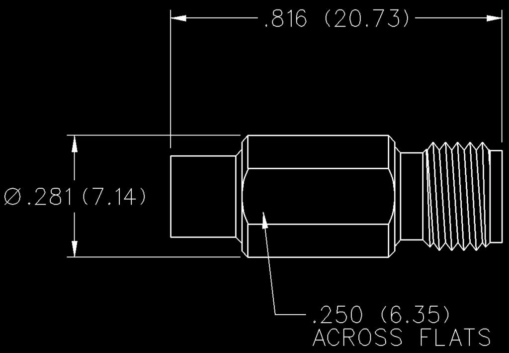
128 Between-Series Adapters SMA to MCX SMA Plug to MCX Jack Adapter VSWR & FREQUENCY RANGE f (GHz) 0-6 GHz GOLD PLATED SMA Plug to MCX Plug Adapter VSWR & FREQUENCY RANGE f (GHz) 0-6 GHz GOLD PLATED SMA Jack to MCX Jack Adapter VSWR & FREQUENCY RANGE f (GHz) 0-6 GHz GOLD PLATED SMA Jack to MCX Plug Adapter VSWR & FREQUENCY RANGE f (GHz) 0-6 GHz GOLD PLATED Connectivity Solutions Tel: Fax:


 0-6 GHz GOLD PLATED 134-1019-171 SMA")


129 Between-Series Adapters SMA to MMCX SMA Plug to MMCX Jack Adapter VSWR & FREQUENCY RANGE f (GHz) 0-6 GHz GOLD PLATED SMA Plug to MMCX Plug Adapter VSWR & FREQUENCY RANGE f (GHz) 0-6 GHz GOLD PLATED SMA Jack to MMCX Jack Adapter VSWR & FREQUENCY RANGE f (GHz) 0-6 GHz GOLD PLATED SMA Jack to MMCX Plug Adapter VSWR & FREQUENCY RANGE f (GHz) 0-6 GHz GOLD PLATED Connectivity Solutions Tel: Fax:


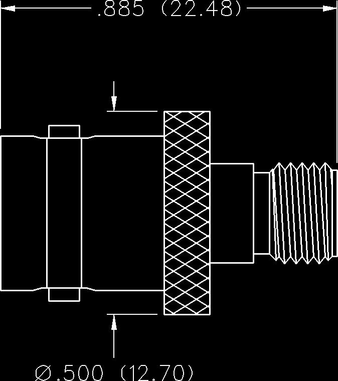
130 Between-Series Adapters BNC to SMA BNC Plug to SMA Plug Adapter PART NO. CP-AD582 BNC Jack to SMA Plug Adapter PART NO. CP-AD508 BNC Plug to SMA Jack Adapter PART NO. CP-AD583 BNC Jack to SMA Jack Adapter PART NO. CP-AD Connectivity Solutions Tel: Fax:


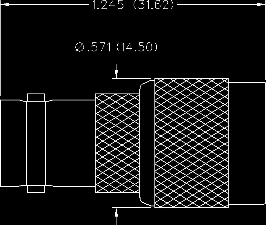
131 Between-Series Adapters BNC to N BNC Plug to N Jack Adapter PART NO. CP-AD807 BNC Jack to N Jack Adapter PART NO. CP-AD806 BNC Jack to N Plug Adapter PART NO. CP-AD809 BNC Plug to TNC Jack Adapter PART NO. CP-AD314 BNC Jack to TNC Plug Adapter PART NO. CP-AD300 Connectivity Solutions Tel: Fax:


132 Between-Series Adapters BNC to F, RCA and UHF BNC to F BNC Jack to F Plug Adapter BNC Plug to F Jack Adapter CP-AD502 CP-AD516 BNC to RCA BNC Jack to RCA Plug Adapter BNC 50 Ohm Plug to RCA Jack Adapter BNC 75 Ohm Plug to RCA Jack Adapter CP-AD501 CP-AD515 CP-AD517 BNC to UHF BNC Jack to UHF Plug Adapter BNC Plug to UHF Jack Adapter CP-AD500 CP-AD Connectivity Solutions Tel: Fax:


133 Between-Series Adapters TNC to SMA TNC Plug to SMA Plug Adapter PART NO. CP-AD311 TNC Jack to SMA Plug Adapter PART NO. CP-AD312 TNC Plug to SMA Jack Adapter PART NO. CP-AD313 Connectivity Solutions Tel: Fax:


134 Between-Series Adapters N to SMA and UHF N Plug to SMA Plug Adapter PART NO. CP-AD817 N Jack to SMA Plug Adapter PART NO. CP-AD818 N Plug to SMA Jack Adapter PART NO. CP-AD810 N Jack to SMA Jack Adapter PART NO. CP-AD819 N Plug to UHF Jack Adapter PART NO. CP-AD Connectivity Solutions Tel: Fax:


135 Between-Series Adapters F to RCA and UHF, UHF to Mini-UHF F to RCA F Jack to RCA Plug Adapter CP-AD103 F to UHF F Jack to UHF Plug Adapter CP-AD218 UHF to Mini-UHF UHF Jack to Mini-UHF Plug Adapter UHF Plug to Mini-UHF Jack Adapter CP-AD214 CP-AD219 Connectivity Solutions Tel: Fax:
136 BNC Connectors Alphabetical Index BNC Connectors - 50 Ohm Bulkhead and Panel Mount Flexible Cable In-Series Adapters Specifications BNC Connectors - 75 Ohm Commercial BNC Connectors - True 75 Ohm Other Information Assembly Instructions Assembly Tools Cable Assembly Cable Information Capabilities Mounting Hole Layouts Numerical Index Ordering Information... 2 Competitor Cross Reference Connectivity Solutions Tel: Fax:
137 BNC Connectors - 50 Ohm Commercial Specifications The BNC series connector is a commercial quality product that intermates with all standard double bayonet stud BNC designs. All contacts are captivated for ruggedness. The 50 Ohm and 75 Ohm interfaces are intermateable and provide quick, reliable connections for instrumentation, medical and LAN applications. Specifications* 50 Ohm BNC Electrical Characteristics Impedance: 50 Ohm nominal Frequency range: 0-4 GHz Working voltage: 500 volts RMS at sea level Dielectric withstanding voltage: 1500 volts RMS at sea level Corona level: 375 volts minimum at 70,000 feet Contact resistance: Outer milliohms maximum Center milliohms maximum Insulation resistance: 5000 megohms minimum Environmental Characteristics Recommended temperature range: -55 O C to +85 O C Moisture resistance: MIL-STD-202 Mechanical Characteristics Durability: 500 cycles Force to engage/disengage: 3 lbs. maximum Cable retention: 20 lbs., RG-58 C/U cable Materials Body: Zinc or brass Contact: Brass, Beryllium copper or phosphor bronze Spring Washer: Beryllium copper Crimp sleeve: Brass Insulator: Delrin or TPX Polymethylpentene Plating: Body - Nickel (except where noted) Crimp sleeve - Nickel Contact - Gold * These values are typical and may not apply to all connectors. Connectivity Solutions Tel: Fax:
.0245 (0.62).093 (2.36).178 (4.52) Crimp Sleeve 3 CPM-88-19 RG-174, 188, 316 0.932 (23.67).0245 (0.62).167 (4.24).")
.595 (15.11).044 (1.12).126 (3.20).206 (5.")
138 BNC Connectors - 50 Ohm Commercial For Flexible Cable Straight Crimp Type Plug - Solder or Crimp Contact - 3 and 4 Piece PART NO. CABLE TYPE A CONTACT I.D. BODY I.D. SLEEVE I.D. TERMINATION PIECES CPMC RG-174, 188, (29.00).0245 (0.62).093 (2.36).178 (4.52) Crimp Sleeve 3 CPM RG-174, 188, (23.67).0245 (0.62).167 (4.24).118 (3.00) Crimp Insert 4 CPM A/S RG-174, 188, (32.31).0245 (0.42).167 (4.24).118 (3.00) Extended Crimp Insert 4 CPM RG-179, (23.67).0165 (0.42).167 (4.24).118 (3.00) Crimp Insert 4 Assembly instructions pages 246 and 247. Straight Crimp Type Plug - Solder or Crimp Contact - 3 Piece PART NO. CABLE TYPE A B CONTACT I.D. BODY I.D. SLEEVE I.D. CPMC-88-1 RG-58, (13.20).595 (15.11).044 (1.12).126 (3.20).206 (5.23) CPMC-88-2 RG-59, (13.20).595 (15.11).034 (0.86).173 (4.39).261 (6.63) CPMC-88-3 BELDEN (15.24).645 (16.38).034 (0.86).208 (5.28).344 (8.74) CPMC-88-5 RG (12.70).645 (16.38).044 (1.12).208 (5.28).280 (7.11) CPMC RG-59 PLENUM, 62 PLENUM.520 (13.20).595 (15.11).0325 (0.83).141 (3.58).206 (5.23) CPMC RG-58 PLENUM; RG (13.74).595 (15.11).044 (1.12).126 (3.20).192 (4.88) CPMC RG-142, 223, 400, (13.20).595 (15.11).044 (1.12).126 (3.20).220 (5.59) CPMC RG-180, 34M, (13.20).595 (15.11).0165 (0.42).107 (2.72).175 (4.45) CPMC RG-8X (MINI 8).520 (13.20).595 (15.11).065 (1.65).173 (4.39).261 (6.63) CPMC BELDEN 8218, MINI (13.20).595 (15.11).0245 (0.62).107 (2.72).175 (4.45) CPMC RG-58, RG-59 PLENUM (31.45) (29.03).034 (0.86).172 (4.37).213 (5.41) CPMC RG-11, BELDEN 1523A.709 (18.00).763 (19.38).067 (1.70).291 (7.90).417 (10.60) Assembly instructions page Connectivity Solutions Tel: Fax:
.605 (15.37) 22-18.025 (.064)-.043 (1.09).195 (4.95)-.210 (5.33) CP-88-2 RG-59, 62, RG-6 PLENUM, GENESIS 5352 SOLID.673 (17.09).605 (15.37) 22-18.025 (.064)-.043 (1.09).220(5.59)-.250 (6.")
-.251 (6.38) CP-88-5 RG-6 SOLID.684 (17.37).605 (15.37) 22-18.025 (.064)-.043 (1.09).265 (6.73)-.280 (7.11) CP-88-10 RG-59, 62 PLENUM SOLID.680 (17.27).605 (15.37) 22-18.025 (.064)-.043 (1.09).195 (4.")
139 BNC Connectors - 50 Ohm Commercial For Flexible Cable Straight Crimp Type Plug - Push-On Body - 2 Piece PART CABLE CABLE CENTER WIRE WIRE JACKET NO. TYPE CONDUCTOR A B GAUGE DECIMAL O.D. CP-88-1 RG-58 SOLID.684 (17.37).605 (15.37) (.064)-.043 (1.09).195 (4.95)-.210 (5.33) CP-88-2 RG-59, 62, RG-6 PLENUM, GENESIS 5352 SOLID.673 (17.09).605 (15.37) (.064)-.043 (1.09).220(5.59)-.250 (6.35) CP-88-3 BELDEN 8281, RG-6 QUAD SOLID.819 (20.80).540 (13.72) (.064)-.043 (1.09).272 (6.91)-.307 (7.80) CP-88-4 RG-MATV-59 SOLID.677 (17.20).605 (15.37) (.064)-.043 (1.09).242 (6.15)-.251 (6.38) CP-88-5 RG-6 SOLID.684 (17.37).605 (15.37) (.064)-.043 (1.09).265 (6.73)-.280 (7.11) CP RG-59, 62 PLENUM SOLID.680 (17.27).605 (15.37) (.064)-.043 (1.09).195 (4.95)-.210 (5.33) CP-SW88-2 RG-59, 62, RG-6TFE STRANDED.673 (17.09).605 (15.37) (.064)-.043 (1.09).220 (5.59)-.250 (6.35) CP-SW88-10 RG-59AU PLENUM STRANDED.673 (17.09).605 (15.37) (.064)-.043 (1.09).195 (4.95)-.210 (5.33) Assembly instructions page 250. Straight Twist-On Plug - Field Installable - 1 Piece PART CABLE CABLE CENTER WIRE WIRE JACKET NO. TYPE CONDUCTOR GAUGE DECIMAL O.D. CPFI-UG88-1 RG-58 SOLID (.064)-.043 (1.09).185 (4.70)-.205 (5.21) CPFI-UG88-2 RG-59, 62 SOLID (.064)-.043 (1.09).220 (5.59)-.250 (6.35) CPFI-UG88-3 BELDEN 8281, RG-6 QUAD SOLID (.064)-.043 (1.09).272 (6.91)-.307 (7.80) CPFI-UG88-4 RG-MATV-59 SOLID (.064)-.043 (1.09).220 (5.59)-.250 (6.35) CPFI-UG88-5 RG-6 PLENUM SOLID (.064)-.043 (1.09).270 (6.86)-.280 (7.11) CPFI-UG88-10 RG-59 PLENUM, 62 PLENUM SOLID (.064)-.043 (1.09).185 (4.70)-.205 (5.21) Assembly instructions page 251. Connectivity Solutions Tel: Fax:
 1.143 (29.03).034 (0.86).172 (4.37).213 (5.41).261 (6.")

140 BNC Connectors - 50 Ohm Commercial For Flexible Cable Straight Crimp Plug - Two Ferrules - 3 Piece PART NO. CABLE TYPE A CONTACT I.D. BODY I.D. SLEEVE I.D. CPMC RG-58, RG-59 PLENUM (31.45) (29.03).034 (0.86).172 (4.37).213 (5.41).261 (6.63) Assembly instructions page 248. Straight Crimp Plug - Two Ferrules, Push-On Body - 2 Piece PART NO. CP-SW88-21 CABLE TYPE RG-58, RG-59 PLENUM Assembly instructions page Connectivity Solutions Tel: Fax:
141 BNC Connectors - 50 Ohm Commercial For Flexible Cable Straight Crimp Type, Rear Mount Bulkhead Jack - Solder or Crimp Contact - 3 Piece PART NO. CABLE TYPE CP-89-19BM1 RG-174, 188, 316 Assembly instructions page 249. Mounting hole layout figure 24 page 203. Tapered crimp sleeve as shown in photo. Straight Crimp Type, Front Mount Bulkhead Jack - Lug Terminal, Solder or Crimp Contact - 3 Piece PART NO. CABLE TYPE CP-89-27BM2 RG-178, 196 Assembly instructions page 249. Mounting hole layout figure 25 page 203. Connectivity Solutions Tel: Fax:

-.250 (6.")
.")
 22.025 (0.64).220 (5.35) Assembly instructions page 250.")
142 BNC Connectors - 50 Ohm Commercial For Flexible Cable Straight Twist-On Jack - Field Installable - 1 Piece PART CABLE CABLE CENTER WIRE WIRE JACKET NO. TYPE CONDUCTOR GAUGE DECIMAL O.D. CPFI-UG89-2 RG-59, 62 SOLID (0.64).220 (5.59)-.250 (6.35) Straight Crimp Type Jack - Push-On Body - 2 Piece PART CABLE CABLE CENTER WIRE WIRE JACKET NO. TYPE CONDUCTOR A B GAUGE DECIMAL O.D. CP-89-1 RG-58 SOLID.680 (17.27).668 (16.97) (0.81).195 (4.95)-.210 (5.33) CP-89-2 RG-59, 62 SOLID.673 (17.09).675 (17.15) (0.64).220 (5.59)-.250 (6.35) Assembly instructions page Connectivity Solutions Tel: Fax:


143 BNC Connectors - 50 Ohm Commercial PC Mount Straight Jack Receptacle PART NO. NOTES CP-BNCPC-001 Silver plated body Mounting hole layout figure 26 page 203. Straight Bulkhead Jack Receptacle - Shielded PART NO. CP-BNCPC-005 Mounting hole layout figures 24 and 27 page 203. Straight Bulkhead Jack Receptacle - Isolated PART NO. CP-BNCPC-007 Mounting hole layout figures 24 and 27 page 203. Connectivity Solutions Tel: Fax:


144 BNC Connectors - 50 Ohm Commercial PC Mount Right Angle Bulkhead Jack Receptacle - Shielded PART NO. CP-BNCPC-009 Mounting hole layout figures 24 and 28 page 203. Right Angle Bulkhead Jack Receptacle - Shielded, Extra Low Profile PART NO. CP-BNCPC-013 NOTES Tin plated body Mounting hole layout figures 24 and 29 pages 203 and 204. Right Angle Bulkhead Jack Receptacle - Isolated, Low Profile PART NO. CP-BNCPC-017 NOTES With mounting posts Mounting hole layout figures 24 and 28 page Connectivity Solutions Tel: Fax:

 w/o solder lug CP-1094-U.371 (9.42).155 (3.")


 dia.")
145 BNC Connectors - 50 Ohm Commercial Bulkhead and Panel Mount Front Mount Bulkhead Jack Receptacle PART NO. A B NOTES CP-625U.425 (10.80).183 (4.65) w/o solder lug CP-1094-U.371 (9.42).155 (3.94) w/o solder lug Mounting hole layout for part number CP-625U figure 30 page 204. Mounting hole layout for part number CP-1094-U figure 25 page 203. Front Mount Bulkhead Jack Receptacle - with Solder Tab PART NO. CP-1094-AST Mounting hole layout figure 25 page 203. Flange Mount Jack Receptacle PART NO. CP-AD519 NOTES.126 (3.20) dia. mounting holes Mounting hole layout figure 31 page 204. Connectivity Solutions Tel: Fax:


146 BNC Connectors - 50 Ohm Commercial In-series Adapters Jack to Jack Adapter PART NO. CP-AD555 Bulkhead Jack to Jack Adapter PART NO. NOTES CP-AD556M w/lock washer Mounting hole layout figure 24 page 203. Bulkhead Jack to Jack Adapter - With Isolation Washers PART NO. CP-AD558 CP-AD521 NOTES w/lock washer Dual Chassis Mount Mounting hole layout figure 32 page Connectivity Solutions Tel: Fax:


147 BNC Connectors - 50 Ohm Commercial In-series Adapters Bulkhead Jack to Jack Adapter - Isolated PART NO. CP-AD580 Mounting hole layout figure 24 page 203. Plug to Plug Adapter PART NO. CP-AD511 Jack to Plug Right Angle Adapter PART NO. CP-AD503 Jack to Jack to Plug T Adapter PART NO. CP-AD505 Connectivity Solutions Tel: Fax:


148 BNC Connectors - 50 Ohm Commercial In-series Adapters Jack to Jack to Jack T Adapter PART NO. CP-AD506 Dust Cap with Chain PART NO. CP-BNC-CAP Connectivity Solutions Tel: Fax:
149 BNC Connectors - 75 Ohm Alphabetical Index BNC Connectors - 75 Ohm Commercial Bulkhead Mount Flexible Cable In-Series Adapters PC Mount Specifications Terminations True 75 Ohm BNC Between-Series Adapters Flexible Cable In-Series Adapters Specifications Other Information Assembly Instructions Assembly Tools Cable Assembly Cable Information Capabilities Mounting Hole Layouts Numerical Index Ordering Information... 2 Competitor Cross Reference Connectivity Solutions Tel: Fax:
150 BNC Connectors - 75 Ohm Commercial Specifications The BNC series connector is a commercial quality product that intermates with all standard double bayonet stud BNC designs. All contacts are captivated for ruggedness. The 50 Ohm and 75 Ohm interfaces are intermateable and provide quick, reliable connections for instrumentation, medical and LAN applications. Specifications* 75 Ohm BNC Electrical Characteristics Impedance: 75 Ohm nominal Frequency range: 0-2 GHz Working voltage: 500 volts RMS at sea level Dielectric withstanding voltage: 1500 volts RMS at sea level Corona level: 375 volts minimum at 70,000 feet Contact resistance: Outer milliohms maximum Center milliohms maximum Insulation resistance: 5000 megohms minimum Environmental Characteristics Recommended temperature range: -55 O C to +85 O C Moisture resistance: MIL-STD-202 Mechanical Characteristics Durability: 500 cycles Force to engage/disengage: 3 lbs. maximum Cable retention: 20 lbs., RG-58 C/U cable Materials Body: Zinc or brass Contact: Brass or Beryllium copper Spring Washer: Beryllium copper Crimp sleeve: Brass Insulator: TPX Plating: Body - Nickel (except where noted) Crimp sleeve - Nickel Contact - Nickel/Gold * These values are typical and may not apply to all connectors. 150 Connectivity Solutions Tel: Fax:
 CPMC-78-3 BELDEN 8281, 9141, 9231.600 (15.24).645 (16.38).563 (14.30) CPMC-78-5 BELDEN RG-6.500 (12.70).645 (16.38).571 (14.50) CPMC-78-10 RG-TFE-59, TFE-62.520 (13.20).595 (15.11).563 (14.30) CPMC-78-18 BELDEN 8218, 1855A, MINI 75.")

 MAX.684 (17.37).605 (15.37) 22-18.333 (8.46) /.284 (7.21) CP-78-10 RG-59 PLENUM, RG-62 PLENUM.600 (17.27).605 (15.37) 22-18.333 (8.46) /.216 (5.49) Assembly instructions page 250.")
151 BNC Connectors - 75 Ohm Commercial For Flexible Cable Straight Crimp Type Plug - Solder or Crimp Contact - 3 Piece PART NO. CABLE TYPE A B C CPMC-78-2 RG-59, (13.20).595 (15.11).563 (14.30) CPMC-78-3 BELDEN 8281, 9141, (15.24).645 (16.38).563 (14.30) CPMC-78-5 BELDEN RG (12.70).645 (16.38).571 (14.50) CPMC RG-TFE-59, TFE (13.20).595 (15.11).563 (14.30) CPMC BELDEN 8218, 1855A, MINI (13.20).595 (15.11).571 (14.50) CPMC-78-20* RG-179, (12.57).633 (16.08).571 (14.50) Assembly instructions page 246. * Denotes tapered crimp sleeve. Straight Twist-On Plug - Field Installable - 1 Piece PART NO. CABLE TYPE CPFI-UG78-2 RG-59, 62 CPFI-UG78-5 RG-6 Assembly instructions page 251. Straight Crimp Type Plug - Push-On Body - 2 Piece PART NO. CABLE TYPE A B WIRE GAUGE SLEEVE I.D. CP-78-2 RG-59, (17.09).605 (15.37) (8.46) /.255 (6.48) CP-78-5 RG-6 QUAD.275 (6.98) MAX.684 (17.37).605 (15.37) (8.46) /.284 (7.21) CP RG-59 PLENUM, RG-62 PLENUM.600 (17.27).605 (15.37) (8.46) /.216 (5.49) Assembly instructions page 250. Connectivity Solutions Tel: Fax:


152 BNC Connectors - 75 Ohm Commercial For Flexible Cable Straight Crimp Type, Rear Mount Bulkhead Jack with O Ring - Solder or Crimp Contact - 3 Piece PART NO. CABLE TYPE CP-79-20BM1 RG-179, 187 Assembly instructions on page 249. Mounting hole layout figure 24 page 203. Tapered crimp sleeve as shown in photo. Straight Crimp Type, Front Mount Bulkhead Jack - Lug Terminal, Solder or Crimp Contact - 3 Piece PART NO. CABLE TYPE CP-79-20BM2 RG-179, 187 Assembly instructions on page 249. Mounting hole layout figure 25 page 203. Tapered crimp sleeve as shown in photo. 152 Connectivity Solutions Tel: Fax:


153 BNC Connectors - 75 Ohm Commercial PC Mount Straight Jack Receptacle PART NO. CP-BNCPC-004 NOTES Tin plated body Mounting hole layout figure 26 page 203. Straight Bulkhead Jack Receptacle - Shielded PART NO. CP-BNCPC-006 Mounting hole layout figures 24 and 27 page 203. Straight Bulkhead Jack Receptacle - Isolated PART NO. CP-BNCPC-008 Mounting hole layout figures 24 and 27 page 203. Right Angle Bulkhead Jack Receptacle - Shielded PART NO. CP-BNCPC-010 Mounting hole layout figures 24 and 28 page 203. Connectivity Solutions Tel: Fax:


154 BNC Connectors - 75 Ohm Commercial PC Mount Right Angle Bulkhead Jack Receptacle - Shielded, Low Profile PART NO. CP-BNCPC-012 Mounting hole layout figures 24 and 28 page 203. Right Angle Bulkhead Jack Receptacle - Shielded, Extra Low Profile PART NO. NOTES CP-BNCPC-014 Tin plated body Mounting hole layout figures 24 and 29 pages 203 and 204. Right Angle Bulkhead Jack Receptacle - Isolated PART NO. NOTES CP-BNCPC-016 With mounting posts Mounting hole layout figures 24 and 28 page Connectivity Solutions Tel: Fax:


155 BNC Connectors - 75 Ohm Commercial Bulkhead Mount Front Mount Bulkhead Jack Receptacle with Lug Terminal PART NO. CP-BNC-BM-001 Mounting hole layout figure 25 page 203. Front Mount Bulkhead Jack Receptacle - Isolated PART NO. CP-AD520 Mounting hole layout figure 25 page 203. Connectivity Solutions Tel: Fax:


156 BNC Connectors - 75 Ohm Commercial In-series Adapters Bulkhead Jack to Jack Adapter - Dual Chassis Mount PART NO. CP-AD557 Mounting hole layout figure 24 page 203. Jack to Jack to Jack T Adapter PART NO. CP-AD584 Jack to Jack to Plug T Adapter PART NO. CP-AD Connectivity Solutions Tel: Fax:

157 BNC Connectors - 75 Ohm Commercial Terminations Terminations PART NO. CODING RESISTANCE POWER CP-88T-75 Purple 75 Ohm +1% 1/2 Watt Connectivity Solutions Tel: Fax:
158 True 75 Ohm BNC Specifications Electrical Characteristics Impedance: 75 Ohm Frequency range: 0-3 GHz VSWR: F (F in GHz) BNC Cabled Plugs F (F in GHz) BNC Adapters Working voltage: 500 VRMS at sea level Dielectric withstanding voltage: 1500 VRMS at sea level Insulation resistance: 5000 megohms minimum Contact resistance: Outer - Nickel plated initial 2.5 milliohm max, after environmental 3.5 milliohm max Center - Initial 3 milliohm max, after environmental 4 milliohm max Braid to Body milliohm max (nickel plated), after environmental not applicable Corona level: 375 volts minimum at 70,000 feet RF High Potential Withstanding Voltage: 700 VRMS at 4 and 7 MHz Environmental Characteristics (Meets or exceeds the applicable paragraph of MIL-C-39012) Thermal shock: MIL-STD-202, Method 107 Operating temperature: -65 O C to +165 O C Corrosion: MIL-STD-202, Method 101, Condition B Shock: MIL-STD-202, Method 213, Condition B Vibration: MIL-STD-202, Method 204, Condition B Moisture resistance: MIL-STD-202, Method 106 Mechanical Characteristics Durability: 500 cycles min Force to engage/disengage: 5 lbs. max, after durability 5 lbs max; 1 lb. min. Coupling nut retention: 100 lbs. min Contact retention: 6 lbs. min axial force Material Specifications Body: Brass, nickel plated.0001 min over copper plated min Contact: Brass, gold plated min over nickel plated min over copper plated min Crimp Sleeve: Copper, nickel plate.0001 min over copper plated min Nut: Zinc, nickel plated over copper plated Insulator: Teflon Spring Washer: Beryllium Copper (unplated) Flat Washer: Steel, nickel plated Gasket: Silicone rubber True 75 Ohm BNC Plug and Jack Mating Engagement 158 Connectivity Solutions Tel: Fax:
.152 (3.86).252 (6.")
159 BNC Connectors - True 75 Ohm For Flexible Cable Straight Cabled Plug - 3 Piece - Solder or Crimp Captivated Contact PART NO. CABLE TYPE CONTACT I.D. BODY I.D. SLEEVE I.D. CPMC-68-2 RG-59, 140, 302, Belden 9209A, 8279, 8241, 8263,.028 (0.71).152 (3.86).252 (6.40) Commscope 5563, Gepco VJ59U CPMC-68-3 Belden 8281, 9231, 9141, 728A, Commscope 7501, VP618VC.036 (0.91).203 (5.16).330 (8.38) CPMC-68-5 RG-6, Belden (0.84).191 (4.85).355 (9.01) CPMC Belden 82108, 89108, Coleman (0.91).149 (3.78).234 (5.94) CPMC Belden (0.53).105 (3.81).180 (4.57) CPMC RG-179, 187, Belden 1520A.016 (0.53).067 (1.70).128 (3.25) CPMC Belden 735A, Commscope 735, Helex/Hitemp 735, BT3002, TZC (0.53).082 (2.08).160 (4.06) CPMC Belden 1855A, 720A, Commscope 7538, Gepco VDM 230, VDM 250, Mini (0.71).105 (3.81).180 (4.57) CPMC Belden 1505A, 734A, Commscope 5565, Gepco VPM (0.91).152 (3.86).252 (6.40) CPMC Belden 1695A, , Gepco VSD 2001TS,.044 (1.12).176 (4.47).265 (6.73) Commscope 2277V CPMC Belden 1694A, 9248, 1152, Commscope 5765, 2227K, Gepco VSD 2001, RG-6 Quad.275 (6.98) Max O.D..044 (1.12).187 (4.75).290 (7.37) CPMC Belden 1506A, 82259, 89259, Gepco VPM2000TK, VPM2000TS.036 (0.91).138 (3.51).234 (5.94) Assembly instructions page 252. Connectivity Solutions Tel: Fax:


160 BNC Connectors - True 75 Ohm In-Series Adapters Jack to Jack Adapter PART NO. CP-AD587 Plug to Plug Adapter PART NO. CP-AD585 Jack to Plug Adapter PART NO. CP-AD Connectivity Solutions Tel: Fax:


161 BNC Connectors - True 75 Ohm Between-Series Adapters BNC Jack to N Jack Adapter PART NO. CP-AD822 BNC Plug to N Jack Adapter PART NO. CP-AD821 Mating Engagement for 75 Ohm N Series PLUG JACK NOTES: 1. ID to meet VSWR and contact resistance when mated with.035/.037 dia pin. 2. Clearance for mating connector coupling nut Ohm N series connectors are not compatible with 50 Ohm N series connectors. Connectivity Solutions Tel: Fax:
162 Boots and Strain Reliefs Cable Boots and Strain Reliefs BK (Black) Packed 100 per bag 25-B58 (Black) For RG-58, 141 Packed 100 per bag 25-B174 (Black) For RG-174 Packed 100 per bag Figure 1 Figure 2 Figure 3 PART NO. CABLE TYPE COLOR PACKAGING FIGURE BK RG-58, 141 BLACK 100 pcs/bag BK RG-59, 62 BLACK 100 pcs/bag 1 25-B58 RG-58, 141 BLACK 100 pcs/bag 2 25-B174 RG-174 BLACK 100 pcs/bag Connectivity Solutions Tel: Fax:
163 TNC/N/F/UHF/Mini-UHF Connectors Alphabetical Index TNC Connectors Flexible Cable In-Series Adapters Specifications RF Adapter Kit Adapters N Connectors Panel Mount and In-Series Adapters Flexible Cable Specifications F Series Connectors Flexible Cable Straight, Right Angle PC Mount, Terminations, Adapters Specifications UHF Connectors Bulkhead Mounts and Adapters Flexible Cables Specifications Mini-UHF Connectors Flexible Cable Specifications Other Information Assembly Instructions Assembly Tools Cable Assembly Cable Information Capabilities Mounting Hole Layouts Numerical Index Ordering Information... 2 Competitor Cross Reference Connectivity Solutions Tel: Fax:
164 TNC Connectors Specifications The TNC connector is a threaded version of the BNC mating interface. All contacts are captivated for ruggedness. The TNC is a commercial quality connector that provides additional coupling retention for shock and vibration applications. The TNC connector intermates with all standard 50 Ohm TNC connectors. Electrical Characteristics Impedance: 50 Ohm nominal (except where noted) Frequency range: 0-11 GHz Working voltage: 500 volts RMS at sea level Dielectric withstanding voltage: 1500 volts RMS at sea level Corona level: 375 volts minimum at 70,000 feet Contact resistance: Outer milliohms maximum Center milliohms maximum Insulation resistance: 5000 megohms minimum Environmental Characteristics Recommended temperature range: -55 O C to +85 O C Moisture Resistance: MIL-STD-202 Mechanical Characteristics Durability: 500 cycles Cable retention: 20 lbs., RG-58 C/U cable Materials Body and coupling nut: Zinc or brass Contact: Beryllium copper, phosphor bronze or brass Crimp Sleeve: Brass Insulator: Teflon, TPX or Delrin Hardware: Brass Plating: Specifications* Body - Nickel Crimp sleeve - Nickel Hardware - Nickel Contact - Gold * These values are typical and may not apply to all connectors. Delrin and Teflon are registered trademarks of Dupont Corporation. 164 Connectivity Solutions Tel: Fax:
.126 (3.20).206 (5.")
.220 (5.59) CPMC-TNC-16 Proflex RG-450.055 (1.40).173 (4.39).261 (6.63) CPMC-TNC-17 RG-8X (MINI 8), LMR 240.")

 Crimp Insert CPM-TNC-20 RG-179, 187.0165 (0.42).167 (4.24).118 (3.")
165 TNC Connectors For Flexible Cable Straight Crimp Type Plug - Solder or Crimp Contact - 3 Piece PART NO. CABLE TYPE CONTACT I.D. BODY I.D. SLEEVE I.D. CPMC-TNC-1 RG-58, (1.12).126 (3.20).206 (5.23) CPMC-TNC-2 RG-59, (0.86).173 (4.39).261 (6.63) CPMC-TNC-13 RG-142, 223, 400, (1.12).126 (3.20).220 (5.59) CPMC-TNC-16 Proflex RG (1.40).173 (4.39).261 (6.63) CPMC-TNC-17 RG-8X (MINI 8), LMR (1.65).173 (4.39).261 (6.63) Assembly instructions page 253. Straight Crimp Type Plug - Solder or Crimp Contact - 4 Piece PART NO. CABLE TYPE CONTACT I.D. BODY I.D. SLEEVE I.D. TERMINATION CPM-TNC-19 RG-174, 188, (0.62).167 (4.24).118 (3.00) Crimp Insert CPM-TNC-20 RG-179, (0.42).167 (4.24).118 (3.00) Crimp Insert Assembly instructions page 247. Connectivity Solutions Tel: Fax:


166 TNC Connectors For Flexible Cable and In-Series Adapters Straight Crimp Type, Rear Mount Bulkhead Jack - Solder or Crimp Contact - 3 Piece PART NO. CABLE TYPE CP-TNC BM RG-174, 188, 316 Assembly instructions page 253. Mounting hole layout figure 24 page 203. Right Angle Bulkhead Jack Receptacle - Shielded PART NO. CPM-TNC-PC-002 Mounting hole layout figures 24 and 28 page Connectivity Solutions Tel: Fax:


167 TNC Connectors In-Series Adapters Jack to Jack Adapter PART NO. CP-AD355 Jack to Bulkhead Jack Adapter PART NO. CP-AD356 Mounting hole layout figure 24 page 203. Connectivity Solutions Tel: Fax:
168 RF Adapter Kit Specifications RF Adapter Kit New PART NO PART NO. DESCRIPTION QTY. PART NO. DESCRIPTION QTY SMA Jack to Bkhd. Jack, Gold Pl. 4 CP-AD515 BNC Plug to RCA Jack SMA Jack to Jack, Gold Pl. 2 CP-AD555 BNC Jack to Jack SMA Plug to Plug, Gold Pl. 4 CP-AD556M BNC Jack to Bkhd. Jack SMA Plug to Jack, Gold Pl. 4 CP-AD582 SMA Plug to BNC Plug RA SMA Jack to Jack, Gold Pl. 2 CP-AD583 SMA Jack to BNC Plug RA SMA Plug to Plug, Gold Pl. 2 CP-AD800 N Plug to Plug RA SMA Plug to Jack, Gold Pl. 4 CP-AD356 TNC Jack to Bkhd. Jack SMA Dummy Load Plug, Gold Pl. 2 CP-AD809 N Plug to BNC Jack 2 CP-AD503 BNC RA BNC Plug to Jack 2 CP-AD810 N Plug to SMA Jack 2 CP-AD505 BNC Jack to Plug to Jack (T) 2 CP-AD817 N Plug to SMA Plug 2 CP-AD506 BNC Jack to Jack to Jack (T) 2 CP-AD818 N Jack to SMA Plug 2 CP-AD507 SMA Jack to BNC Jack 3 CP-AD819 N Jack to SMA Jack 2 CP-AD508 SMA Plug to BNC Jack 3 CP-AD850 N Jack to Jack 2 CP-AD511 BNC Plug to Plug 3 CP-AD851 N Jack to Bkhd. Jack 2 TOTAL: 72 Adapters 168 Connectivity Solutions Tel: Fax:
169 N Connectors Specifications The N connector employs a large diameter threaded interface for excellent strength and reliability. This commercial quality connector handles high power applications such as antenna feeds for radios and cell sites. Termination options include crimp and clamp styles for rugged service. Specifications* Electrical Characteristics Impedance: 50 Ohm nominal Frequency range: 0-11 GHz Working voltage: 500 volts RMS at sea level Dielectric withstanding voltage: 1500 volts RMS at sea level Corona level: 375 volts minimum at 70,000 feet Contact resistance: Outer milliohms maximum Center milliohms maximum Insulation resistance: 5000 megohms minimum Environmental Characteristics Recommended temperature range: -55 O C to + 85 O C Moisture Resistance: MIL-STD-202 Mechanical Characteristics Durability: 500 cycles Cable retention: 20 lbs., RG-58 C/U cable Materials Body and coupling nut: Brass Contact: Brass, phosphor bronze or beryllium copper Crimp sleeve: Brass Insulator: Teflon or Delrin Hardware: Brass Plating: Body - Nickel Crimp sleeve - Nickel Hardware - Nickel Contact - Gold * These values are typical and may not apply to all connectors. Delrin and Teflon are registered trademarks of Dupont Corporation. Connectivity Solutions Tel: Fax:
.042 (1.07).125 (3.18).212 (5.38) CPN-68-8 RG-8, 213 1.385 (35.18).093 (2.36).")

.300 (7.62).420 (10.67) CPN-8/110 RG-8, 213, LMR 400 1.550 (39.37).110 (2.79).300 (7.62).420 (10.67) CPN-16 PROFLEX RG-450 1.455 (36.96).")
.125 (3.18).220 (5.59) Assembly instructions page 255. 170 Connectivity Solutions Tel: 800-247-8256 Fax: 507-833-6287 www.")
170 N Connectors For Flexible Cable and Bulkhead Mount Straight Crimp Type Plug - Solder or Crimp Contact PART NO. CABLE TYPE A CONTACT I.D. BODY I.D. SLEEVE I.D. CPN-68-1 RG-58; BELDEN (33.78).042 (1.07).125 (3.18).212 (5.38) CPN-68-8 RG-8, (35.18).093 (2.36).293 (7.44).430 (10.92) CPN RG-142, 223, (33.78).042 (1.07).127 (3.23).223 (5.66) Assembly instructions page 254. Straight Crimp Type Plug Second Termination - 3 Piece PART NO. CABLE TYPE A CONTACT I.D. BODY I.D. SLEEVE I.D. CPN-1 RG (36.83).044 (1.12).125 (3.18).206 (5.23) CPN-2 RG-59, (36.83).0325 (0.83).173 (4.39).261 (6.63) CPN-8 RG-8 Types (39.37).089 (2.26).300 (7.62).420 (10.67) CPN-8/110 RG-8, 213, LMR (39.37).110 (2.79).300 (7.62).420 (10.67) CPN-16 PROFLEX RG (36.96).055 (1.40).173 (4.39).261 (6.63) CPN-17 RG8X (MINI 8) (36.96).065 (1.65).173 (4.39).261 (6.63) CPN-142T RG-142 TFE (36.96).044 (1.12).125 (3.18).220 (5.59) Assembly instructions page Connectivity Solutions Tel: Fax:

 Typical VSWR Frequency Range (GHz) RG-316 cable... 1.20 0-2 1.50 2-11 RG-58 cable... 1.30 0-5 1.70 5-11 RG-142 cable... 1.20 0-5 1.")
171 N Connectors For Flexible Cable Straight Crimp Type Bulkhead Jack - Diecast Body PART NO CABLE TYPE RG-161/U, 174,188, 316 RG-188 DS, RG-316 DS RG-58/U, 141, 303 RG-55/U, 142, 223, 400 Assembly instructions page 241. Mounting hole layout figure 11 page 201. N connector plug also available. ELECTRICAL RATINGS Impedance: 50 Ohms Frequency Range: 0-11 GHz VSWR: (f = GHz) Typical VSWR Frequency Range (GHz) RG-316 cable RG-58 cable RG-142 cable Working Voltage: (VRMS maximum) Connectors for Cable Type Sea Level 70K Feet RG RG RG Dielectric Withstanding Voltage: (VRMS minimum at sea level) RG RG RG Insulation Resistance: 5000 megohms minimum Contact Resistance: (milliohms maximum) After Initial Environmental Center contact Outer contact N/A Braid to body N/A ** All gold plated parts include a.00005" min. nickel underplate barrier layer. Avoid user injury due to misapplication. See safety advisory definitions inside front cover. MECHANICAL RATINGS Engagement Design: MIL-STD-348, series N Engagement Force/Disengagement Force: 6 inch-pounds maximum Mating Torque: 6 to 10 inch-pounds Cable Retention: Axial Force (lbs)* RG RG RG * Or cable breaking strength whichever is less. Durability: 500 cycles minimum ENVIRONMENTAL RATINGS (Meets or exceeds the applicable paragraph of MIL-C-39012) Temperature Range: - 65 C to C Thermal Shock: MIL-STD-202, Method 107, Condition B Corrosion: MIL-STD-202, Method 101, Condition B Shock: MIL-STD-202, Method 213, Condition I Vibration: MIL-STD-202, Method 204, Condition B Moisture Resistance: MIL-STD-202, Method 106 MATERIAL SPECIFICATIONS Bodies: Main body - zinc per ASTM B86-71, nickel plated per QQ-N-290 Rear body - brass per QQ-B-626, nickel plated per QQ-N-290 Contacts: Beryllium copper per QQ-C-530, gold plated** per MIL-G-45204,.00001" min. Insulators: PTFE fluorocarbon per ASTM D 1710 and ASTM D 1457 Crimp Sleeves: Copper per WW-T-799, nickel plated per QQ-N-290 Mounting Hardware: Nut - brass per QQ-B-626, nickel plated per QQ-N-290 Lockwasher - steel per QQ-S-700, zinc plated per QQ-Z-325 Connectivity Solutions Tel: Fax:


172 N Connectors Panel Mount and In-Series Adapters Flange Mount Jack Receptacle PART NO. CP-AD801 Mounting hole layout figure 34 page 204. Jack to Jack Adapter PART NO. CP-AD850 Jack to Bulkhead Jack Adapter PART NO. CP-AD851 Mounting hole layout figure 33 page 204. Plug to Plug Adapter PART NO. CP-AD Connectivity Solutions Tel: Fax:
173 F Series Connectors Specifications The F Connector provides economical distribution of audio/video TV signals. The F Plug Connector typically employs the center conductor of the cable as the male contact for quick assembly in the field. Specifications* F Series Electrical Characteristics Impedance: 75 Ohms Frequency range: MHz Working voltage: 500 VRMS max at sea level Dielectric withstanding voltage: 1500 VRMS max at sea level Insulation resistance: 5000 megohms Environmental Characteristics Temperature range: -55 O C to +85 O C Moisture resistance: MIL-STD-202 Mechanical Characteristics Durability: 100 cycles Cable retention: 20 lbs. * These values are typical and may not apply to all connectors. Connectivity Solutions Tel: Fax:
 CPF-59-1/2 Crimp Tool Hex Size 24-7710.255 (6.48) CPF-59-ALM Crimp Tool Hex Size 24-7710.")
 CPF-59-CP Compression Tool 24-7713P F Series Connectors For RG-6 Straight Crimp Plug for RG-6 Straight Crimp Plug for Tri-Shield Straight Crimp Plug for RG-6 Quad Shield Straight Crimp Plug for")
 Straight Crimp Plug.324 dia.")
174 F Series Connectors For Flexible Cable F Series Connectors For RG-59 Straight Crimp Plug w/separate 1/4 crimp ring Straight Crimp Plug w/separate 1/2 crimp ring Straight Crimp Plug for standard RG-59 cable Straight Crimp Plug compression F RG-59 dual Tri/Shield CPF-59-1/4 Crimp Tool Hex Size (6.48) CPF-59-1/2 Crimp Tool Hex Size (6.48) CPF-59-ALM Crimp Tool Hex Size (8.18) CPF-59-CP Compression Tool P F Series Connectors For RG-6 Straight Crimp Plug for RG-6 Straight Crimp Plug for Tri-Shield Straight Crimp Plug for RG-6 Quad Shield Straight Crimp Plug for Teflon/Plenum RG-6 CPF-56-ALM Crimp Tool Hex Size (8.18) CPF-56-ALX Crimp Tool Hex Size (8.18) CPF-56-ALS Crimp Tool Hex Size P.359 (9.12) CPF-56-P Crimp Tool Hex Size (8.18) Straight Crimp Plug.324 dia., chrome plated/ interior gasket for water proofing Straight Plug twist on (no crimp) Straight Crimp Plug compression F RG-6 Dual/Tri/Shield CPF-56-ALMWP Crimp Tool Hex Size (8.18) CPFI-56 CPF-56-CP Compression Tool P F Series Connector For RG-11 Straight Crimp Plug for standard RG-11 CPF-11-ALM Crimp Tool Hex Size P.448 (11.38) 174 Connectivity Solutions Tel: Fax:


175 F Series Connectors F Straight Right Angle PC Mount Connectors, Plug Termination and Adapters F Series Connectors F Straight and Right Angle PC Mount Connectors Side Edge Mount PCB Jack Vertical Mount PCB Jack Right Angle Mount PCB Bulkhead Jack CPF-61-SE CPF-61-PC CPF-61-SR Board Thickness.062 (1.57) F Plug Termination Plug Termination 75 Ohm F, 1/2 watt 5% terminator CPF-59-T F In-Series Adapters Jack to Jack Adapter 3/4 inline splice Jack to Jack Adapter 3/4 w/ nut and washer Jack to Jack Adapter 1 inline splice Nut and Washer For use with all F Bulkhead mounts/splices CPF-81 CPF-81-NW CPF-81-L CPF-NW Connectivity Solutions Tel: Fax:
176 UHF Connectors Specifications The UHF connectors are low cost, general purpose units designed for low frequency system applications. These commercial quality connectors are equipped with threaded coupling interfaces for secure and reliable connections. The standard UHF and Mini-UHF connectors are not intermateable. Specifications* Standard UHF Electrical Characteristics Impedance: Non-constant Frequency range: MHz Working voltage: 500 volts RMS at sea level Dielectric withstanding voltage: 1500 volts RMS at sea level Insulation resistance: 5000 megohms minimum Environmental Characteristics Recommended temperature range: -55 O C to +85 O C Mechanical Characteristics Durability: 500 cycles Cable retention: 20 lbs., RG-58 C/U cable Materials Body and coupling nut: Zinc or Brass Contact: Beryllium copper or Brass Crimp Sleeve: Brass Insulator: Delrin Plating: Body - Nickel Crimp sleeve - Nickel Contact - Gold or Nickel * These values are typical and may not apply to all connectors. Delrin is a registered trademark of Dupont Corporation. 176 Connectivity Solutions Tel: Fax:
-.205 (5.21) CPL-259-2 RG-59, 62.688 (17.48).810 (20.57) 22.0253 (0.64).220 (5.59)-.250 (6.35) CPL-259-7 RG-58 COPHASE.700 (17.78).832 (21.13) 2/20 2/.032 (0.81) 2/.185 (4.70)-.205 (5.21) CPL-259-8 RG-8.")
.205 (5.21)-.220 (5.59) CPL-259-17 RG-8X (MINI 8).696 (17.68).710 (18.03) 16.0504 (1.28).220 (5.59)-.250 (6.35) Assembly instructions page 256.")
177 UHF Connectors For Flexible Cables Straight Crimp Type Plug - Crimp Contact PART CABLE WIRE WIRE JACKET NO. TYPE A B GAUGE DECIMAL O.D. CPL RG (19.15).810 (20.57) (0.83).185 (4.70)-.205 (5.21) CPL RG-59, (17.48).810 (20.57) (0.64).220 (5.59)-.250 (6.35) CPL RG-58 COPHASE.700 (17.78).832 (21.13) 2/20 2/.032 (0.81) 2/.185 (4.70)-.205 (5.21) CPL RG (17.63).820 (20.83) (2.16).400 (10.16)-.410 (10.41) CPL RG-59 COPHASE.700 (17.78).856 (21.74) 2/22 2/.025 (0.64) 2/.220 (5.59) CPL * RG-59 PLENUM.696 (17.68).710 (18.03) (0.83).205 (5.21)-.220 (5.59) CPL RG-8X (MINI 8).696 (17.68).710 (18.03) (1.28).220 (5.59)-.250 (6.35) Assembly instructions page 256. *1-Piece Straight Crimp Type Plug - Crimp Contact, Double Nut PART CABLE WIRE WIRE JACKET NO. TYPE GAUGE DECIMAL O.D. CPL RG (0.88).185 (4.70)-.205 (5.21) Assembly instructions page 256. Connectivity Solutions Tel: Fax:


 Assembly instructions page 257.")
178 UHF Connectors For Flexible Cable, Bulkhead and Adapters Straight Solder Type Plug PART NO. CABLE TYPE DESCRIPTION CP-AD250 RG-8, 213 Standard, PL-259 Straight Crimp Type Jack to Center - Conductor Twist-On - 2 Piece PART CABLE WIRE WIRE JACKET NO. TYPE GAUGE DECIMAL O.D. CPF RG (0.83).185 (4.70)-.205 (5.21) Assembly instructions page Hole Flange Mount Jack PART NO. CP-AD Connectivity Solutions Tel: Fax:


179 UHF Connectors Adapters Jack to Jack Adapter PART NO. CP-AD204 Bulkhead Jack to Bulkhead Jack Adapter PART NO. CP-AD207 Jack to Jack to Jack T Adapter PART NO. CP-AD210 Connectivity Solutions Tel: Fax:
180 Mini-UHF Connector Specifications Mini-UHF connectors are low cost, general purpose units designed for low frequency system applications. These commercial quality connectors are equipped with threaded coupling interfaces for secure and reliable connections. The standard UHF and Mini-UHF connectors are not intermateable. Specifications* Mini-UHF Electrical Characteristics Impedance: Non-constant Frequency range: 0-2 GHz Working voltage: 500 volts RMS at sea level Dielectric withstanding voltage: 1500 volts RMS at sea level Insulation resistance: 5000 megohms minimum Environmental Characteristics Recommended temperature range: -55 O C to +85 O C Mechanical Characteristics Durability: 500 cycles Cable retention: 20 lbs., RG-58 C/U cable Materials Body and coupling nut: Zinc or Brass Contact: Brass Crimp Sleeve: Brass Insulator: TPX Polymethylpetene Plating: Body - Nickel Crimp sleeve - Nickel Contact - Gold or Nickel * These values are typical and may not apply to all connectors. 180 Connectivity Solutions Tel: Fax:
 MINI-UHF-1B RG-58 Black UV Coating.613 (15.57).044 (1.12).126 (3.20).206 (5.23) MINI-UHF-2 RG-59, 62.613 (15.57).034 (0.86).173 (4.39).261 (6.63) MINI-UHF-16 PROFLEX RG-450.610 (15.49).")
181 Mini-UHF Connector For Flexible Cable Straight Crimp Type Plug - Solder or Crimp Contact PART NO. CABLE TYPE A CONTACT I.D. BODY I.D. SLEEVE I.D. MINI-UHF-1 RG (15.49).044 (1.12).126 (3.20).206 (5.23) MINI-UHF-1B RG-58 Black UV Coating.613 (15.57).044 (1.12).126 (3.20).206 (5.23) MINI-UHF-2 RG-59, (15.57).034 (0.86).173 (4.39).261 (6.63) MINI-UHF-16 PROFLEX RG (15.49).055 (1.40).173 (4.39).261 (6.63) MINI-UHF-17 RG-8X (MINI 8).600 (15.24).065 (1.65).173 (4.39).261 (6.63) Assembly instructions page 258. Connectivity Solutions Tel: Fax:
182 Fixed Length RF Cable Assemblies Electrical Ratings Electrical ratings of a cable assembly are determined by the limiting connector type and cable size. Connector Dielectric Working Impedance Frequency Withstanding Voltage Connector Cable (Ohms) (GHz) Voltage (VRMS) (VRMS) MCX RG VRMS 250 VRMS RG VRMS 335 VRMS RG-316 DS VRMS 335 VRMS MCX 75 Ohm RG VRMS 335 VRMS BELDEN 735A VRMS 335 VRMS SMA RG VRMS 170 VRMS RG VRMS 250 VRMS RG-316 DS VRMS 250 VRMS RG VRMS 335 VRMS RG VRMS 335 VRMS SMB RG VRMS 250 VRMS RG VRMS 335 VRMS SMB Mini 75 Ohm RG VRMS 335 VRMS RG-179 DS VRMS 335 VRMS BELDEN 735A VRMS 335 VRMS BNC RG VRMS 500 VRMS BELDEN VRMS 500 VRMS RG VRMS 500 VRMS RG-59 PLENUM VRMS 500 VRMS BNC True 75 Ohm BELDEN VRMS 500 VRMS RG VRMS 500 VRMS BELDEN VRMS 500 VRMS COMMSCOPE VRMS 500 VRMS BELDEN 735A VRMS 500 VRMS BELDEN 734A VRMS 500 VRMS BELDEN 1694A VRMS 500 VRMS N RG VRMS 500 VRMS RG VRMS 500 VRMS RG VRMS 500 VRMS RG VRMS 500 VRMS Cable length is measured to the end of straight connectors and the vertical centroid of right angle connectors. 182 Connectivity Solutions Tel: Fax:

183 Fixed Length Cable Assemblies MCX Straight Plug to MCX Straight Plug Part Cable Cable Connector Connector No. Type Length A B RG-178 6" RG " RG RG " RG " RG " RG-316 6" RG " RG " MCX Straight Plug to MCX Straight Bulkhead Jack Part Cable Cable Connector Connector No. Type Length A B RG-316 6" RG " RG " Part Cable Cable Connector Connector No. Type Length A B RG " RG " RG " RG-316-DS 6" RG-316-DS 12" RG-316-DS 18" RG-316-DS 24" RG-316-DS 30" RG-316-DS 36" Part Cable Cable Connector Connector No. Type Length A B RG " RG " RG " J J J MCX Straight Plug to MCX Right Angle Plug Part Cable Cable Connector Connector Part Cable Cable Connector Connector No. Type Length A B No. Type Length A B RG-316 6" RG " RG " RG " RG " Part Cable Cable Connector Connector MCX Right Angle Plug to MCX Right Angle Plug Part Cable Cable Connector Connector No. Type Length A B RG-178 6" RG " RG " RG " RG " RG " RG-316 6" RG " RG " Part Cable Cable Connector Connector No. Type Length A B RG " RG " RG " RG-316-DS 6" RG-316-DS 12" RG-316-DS 18" RG-316-DS RG-316-DS 30" RG-316-DS 36" J J MCX 75 Ohm Straight Plug to MCX 75 Ohm Straight Plug Part Cable Cable Connector Connector No. Type Length A B RG-179 6" RG " RG " RG " RG " RG " Part Cable Cable Connector Connector No. Type Length A B Belden 735 A 6" Belden 735 A 12" Belden 735 A 18" Belden 735 A 24" Belden 735 A 30" Belden 735 A 36" J Connectivity Solutions Tel: Fax:


184 Fixed Length Cable Assemblies MCX 75 Ohm Right Angle Plug to MCX 75 Ohm Right Angle Plug Part Cable Cable Connector Connector No. Type Length A B Belden 735 A 6" Belden 735 A 12" Belden 735 A 18" SMA Straight Plug to SMA Straight Plug Part Cable Cable Connector Connector No. Type Length A B RG-178 6" RG " RG " RG " RG " RG " RG-316 6" RG " RG " RG " RG " RG " RG-316 DS 6" RG-316 DS 12" SMA Straight Plug to SMA Straight Bulkhead Jack Part Cable Cable Connector Connector No. Type Length A B RG-316 6" RG " RG " RG " RG " RG " RG-316 DS 6" RG-316 DS 12" RG-316 DS 18" RG-316 DS 24" RG-316 DS 36" SMA Straight Plug to SMA Right Angle Plug Part Cable Cable Connector Connector No. Type Length A B RG-178 6" RG " RG " RG " RG " RG " RG-316 6" RG " RG " RG " RG " RG " RG-316 DS 6" RG-316 DS 12" Part Cable Cable Connector Connector No. Type Length A B Belden 735 A 24" Belden 735 A 30" Belden 735 A 36" Part Cable Cable Connector Connector No. Type Length A B RG-316 DS 18" RG-316 DS 24" RG-316 DS 36" RG-316 DS 48" RG-58 12" RG-58 24" RG-58 36" RG-58 48" RG-58 60" RG " RG " RG " RG " RG " Part Cable Cable Connector Connector No. Type Length A B RG-316 DS 48" RG-58 12" RG-58 24" RG-58 36" RG-58 48" RG-58 60" RG " RG " RG " RG " RG " Part Cable Cable Connector Connector No. Type Length A B RG-316 DS 18" RG-316 DS 24" RG-316 DS 36" RG-316 DS 48" RG-58 12" RG-58 24" RG-58 36" RG-58 48" RG-58 60" RG " RG " RG " RG " RG " J J J J 184 Connectivity Solutions Tel: Fax:


185 Fixed Length Cable Assemblies SMA Right Angle Plug to SMA Right Angle Plug Part Cable Cable Connector Connector No. Type Length A B RG-178 6" RG " RG " RG " RG " RG " RG-316 6" RG RG " RG " RG " RG " RG-316 DS 6" RG-316 DS 12" Part Cable Cable Connector Connector No. Type Length A B RG-316 DS 18" RG-316 DS 24" RG-316 DS 36" RG-316 DS 48" RG-58 12" RG-58 24" RG-58 36" RG-58 48" RG-58 60" RG " RG " RG " RG " RG " J SMB Straight Plug to SMB Straight Plug Part Cable Cable Connector Connector No. Type Length A B RG-316 6" RG " RG " Part Cable Cable Connector Connector No. Type Length A B RG " RG " RG " J SMB Straight Plug to SMB Right Angle Plug Part Cable Cable Connector Connector No. Type Length A B RG-316 6" RG " RG " RG " RG " RG " RG-316 DS 6" RG-316 DS 12" RG-316 DS 18" Part Cable Cable Connector Connector No. Type Length A B RG-316 DS 24" RG-316 DS 30" RG-316 DS 36" RG-178 6" RG " RG " RG " RG " RG " J SMB Right Angle Plug to SMB Right Angle Plug Part Cable Cable Connector Connector No. Type Length A B RG-178 6" RG " RG " RG " RG " RG " RG-316 6" RG " RG " Part Cable Cable Connector Connector No. Type Length A B RG " RG " RG " RG-316 DS 6" RG-316 DS 12" RG-316 DS 18" RG-316 DS 24" RG-316 DS 30" RG-316 DS 36" J Connectivity Solutions Tel: Fax:

186 Fixed Length Cable Assemblies SMB Mini-75 Ohm Straight Plug to SMB Mini-75 Ohm Straight Plug Part Cable Cable Connector Connector No. Type Length A B RG-179 6" RG " RG " RG " RG " RG " RG-179 DS 6" RG-179 DS 12" RG-179 DS 18" Part Cable Cable Connector Connector No. Type Length A B RG-179 DS 24" RG-179 DS 30" RG-179 DS 36" Belden 735 A 6" Belden 735 A 12" Belden 735 A 18" Belden 735 A 24" Belden 735 A 30" Belden 735 A 36" J SMB Mini-75 Ohm Right Angle Plug to SMB Mini-75 Ohm Right Angle Plug Part Cable Cable Connector Connector No. Type Length A B RG-179 6" RG " RG " RG " RG " RG " RG-179 DS 6" RG-179 DS 12" RG-179 DS 18" J Part Cable Cable Connector Connector No. Type Length A B RG-179 DS 24" RG-179 DS 30" RG-179 DS 36" Belden 735 A 6" Belden 735 A 12" Belden 735 A 18" Belden 735 A 24" Belden 735 A 30" Belden 735 A 36" N Straight Plug to N Straight Plug Part Cable Cable Connector Connector No. Type Length A B RG-58 12" CPN-1 CPN RG-58 24" CPN-1 CPN RG-58 36" CPN-1 CPN RG-58 48" CPN-1 CPN RG-58 60" CPN-1 CPN RG " CPN-142T CPN-142T RG " CPN-142T CPN-142T RG " CPN-142T CPN-142T RG " CPN-142T CPN-142T RG " CPN-142T CPN-142T Part Cable Cable Connector Connector No. Type Length A B RG-8 12" CPN-8 CPN RG-8 24" CPN-8 CPN RG-8 36" CPN-8 CPN RG-8 48" CPN-8 CPN RG-8 60" CPN-8 CPN RG " CPN-8 CPN RG " CPN-8 CPN RG " CPN-8 CPN RG " CPN-8 CPN RG " CPN-8 CPN-8 J 186 Connectivity Solutions Tel: Fax:


187 Fixed Length Cable Assemblies BNC Straight Plug to BNC Straight Plug BNC True 75 Ohm Straight Plug to BNC True 75 Ohm Straight Plug J With Boot Part Cable Cable Connector Connector No. Type Length A B RG-58 12" CPMC-88-1 CPMC RG-58 24" CPMC-88-1 CPMC RG-58 36" CPMC-88-1 CPMC RG-58 48" CPMC-88-1 CPMC RG-58 60" CPMC-88-1 CPMC RG-59 TFE 12" CPMC CPMC RG-59 TFE 24" CPMC CPMC RG-59 TFE 36" CPMC CPMC RG-59 TFE 48" CPMC CPMC RG-59 TFE 60" CPMC CPMC RG-59 12" CPMC-88-2 CPMC RG-59 24" CPMC-88-2 CPMC RG-59 36" CPMC-88-2 CPMC RG-59 48" CPMC-88-2 CPMC RG-59 60" CPMC-88-2 CPMC-88-2 With Heat Shrink Part Cable Cable Connector Connector No. Type Length A B Belden " CPMC CPMC Belden " CPMC CPMC Belden " CPMC CPMC Belden " CPMC CPMC Belden " CPMC CPMC With Boot Part Cable Cable Connector Connector No. Type Length A B RG-59 12" CPMC-68-2 CPMC RG-59 24" CPMC-68-2 CPMC RG-59 36" CPMC-68-2 CPMC RG-59 48" CPMC-68-2 CPMC RG-59 60" CPMC-68-2 CPMC Belden 734 A 12" CPMC CPMC Belden 734 A 24" CPMC CPMC Belden 734 A 36" CPMC CPMC Belden 734 A 48" CPMC CPMC Belden 734 A 60" CPMC CPMC With Heat Shrink Part Cable Cable Connector Connector No. Type Length A B Belden " CPMC CPMC Belden " CPMC CPMC Belden " CPMC CPMC Belden " CPMC CPMC Belden " CPMC CPMC Belden " CPMC-68-3 CPMC Belden " CPMC-68-3 CPMC Belden " CPMC-68-3 CPMC Belden " CPMC-68-3 CPMC Belden " CPMC-68-3 CPMC COMSCOPE " CPMC CPMC COMSCOPE " CPMC CPMC COMSCOPE " CPMC CPMC COMSCOPE " CPMC CPMC COMSCOPE " CPMC CPMC Belden 735 A 12" CPMC CPMC Belden 735 A 24" CPMC CPMC Belden 735 A 36" CPMC CPMC Belden 735 A 48" CPMC CPMC Belden 735 A 60" CPMC CPMC Belden 1694A 12" CPMC CPMC Belden 1694A 24" CPMC CPMC Belden 1694A 36" CPMC CPMC Belden 1694A 48" CPMC CPMC Belden 1694A 60 CPMC CPMC SMA Straight Plug to N Straight Plug Part Cable Cable Connector Connector No. Type Length A B RG-58 12" CPN RG-58 24" CPN RG-58 36" CPN RG-58 48" CPN RG-58 60" CPN-1 Part Cable Cable Connector Connector No. Type Length A B RG " CPN-142T RG " CPN-142T RG " CPN-142T RG " CPN-142T RG " CPN-142T J Connectivity Solutions Tel: Fax:


188 Fixed Length Cable Assemblies SMA Straight Plug to BNC Straight Plug Part Cable Cable Connector Connector No. Type Length A B RG-316 6" CPM RG " CPM RG " CPM RG " CPM RG " CPM RG " CPM RG-58 12" CPMC RG-58 24" CPMC-88-1 J Part Cable Cable Connector Connector No. Type Length A B RG-58 36" CPMC RG-58 48" CPMC RG-58 60" CPMC RG " CPMC RG " CPMC RG " CPMC RG " CPMC RG " CPMC If you don t see the cable assembly you require, we can design and manufacture one to meet your unique specifications! Voltage/Continuity Test Fixture Interface location gauging VSWR Quality Assurance Scalar Analyzer VSWR/TDR Engineering Vector Analyzer CNC Hardline Bender (Semi-Rigid cables) Tested to customer specifications Flexible cable Conformable cable Semi-Rigid cable 0 to 40 GHz 50 and 75 Ohms Controlled impedance Prototype available in 2 weeks Call to discuss your needs with a Customer Service Representative 188 Connectivity Solutions Tel: Fax:
189 Assembly Tools Alphabetical Index Assembly Tools 3-Piece SMA - Contact Hand Crimp Tool Piece SMB, MCX - Contact Hand Crimp Tool C Spring Compression Tool Economy Hand Crimp Tool Hand Crimp Tool MCX Right Angle Plug Assembly Tool MMCX Assembly/Decoupling Tool Prestige Coax & Telephone Cable Strippers Prestige Professional Ratchet Crimp Tools Prestige Ratchet and Universal Crimp Tools RF and CATV Installation Tools SMA Knurl Mount Assembly Tool SMB Plug Removal Tool SMK (2.92 mm) Tools Connectivity Solutions Tel: Fax:

190 Coaxial Connector Assembly Tools Hand Crimp Tool Precision Astro Tool hand crimping tool makes cable assembly fast and easy. Crimping tool features interchangeable steel dies. Ratchet action of tool controls crimping operation for precise uniform ferrule crimps. CONNECTOR CABLE PREFERRED CRIMP TYPE TYPE DIE SET DIMENSIONS MCX SMA SMB SMC MCX SMA SMB SMC 75 Ohm SMB MCX SMA SMB SMA 75 Ohm SMB RG-178/U RG-196/U RG-161/U, RG-174/U RG-179/U, RG-187/U RG-188/U, RG-316/U LMR-100 RG-188 DS, RG-316 DS RG-179 DS, RG-187 DS, BELDEN 735A RG-58/U RG-141/U RG-303/U RG-55/U RG-142/U RG-223/U RG-400/U LMR-195 LMR-200 LMR-240, RG-59 *Economy Hand Crimp Tool also available with four hex sizes in one tool page N Type RG-316/U, 316 DS Ordering Information for Crimping Tool PART NO. DESCRIPTION ASTRO TOOL P/N Frame Only Single Hex Die Single Hex Die Single Hex Die Single Hex Die Single Hex Die Single Hex Die Crimp Dies for Contacts use with CONNECTOR TYPE PREFERRED DIE SET CRIMP STYLE Hex =.105 (2.67) Width =.325 (8.26) Hex =.128 (3.25) Width =.400 (10.16) Hex =.151 (3.83) Width =.400 (10.16) Hex =.213 (5.41) Width =.375 (9.52) Hex =.255 (6.48) Width =.400 (10.16) Hex =.160 (4.06) Width =.400 (10.16) SMB Cross Hole Style Body 50 Ohm Only Mini 75 Ohm SMB, MCX 75 Ohm Cross Hole Style Body Double Diamond Double Diamond 190 Connectivity Solutions Tel: Fax:
.250 (6.35) Die for.047 dia. flexible cable;.")
 Die for RG-178, 316, 316 DS,.105 (2.67).390 (9.91) 140-0000-951 58, 142, LMR-100, LMR-195,.128 (3.25).390 (9.91) MCX, SMB, SMC, LMR-200.151 (3.83).390 (9.91) SMA, 75 OHM SMB.213 (5.41).390 (9.91) 140-0000-955 Die for RG-179, 179 DS, 735A,.")

191 Coaxial Connector Assembly Tools Economy Hand Crimp Tool Hand crimp tool and die set includes all hex sizes necessary for subminiature connector applications. Ratchet tool action insures a complete crimp every time. PART NO. DESCRIPTION HEX WIDTH CONNECTOR TYPE Hand Crimp Tool Frame Only.105 (2.67).250 (6.35) Die for.047 dia. flexible cable;.128 (3.25).250 (6.35) RG-178, RG-316, RG-316 DS.151 (3.83).250 (6.35) MMCX*, MCX and Contact Crimp w/stop Diamond Crimp for.038 (0.96) Dia. Contact.035 (0.89) Die for RG-178, 316, 316 DS,.105 (2.67).390 (9.91) , 142, LMR-100, LMR-195,.128 (3.25).390 (9.91) MCX, SMB, SMC, LMR (3.83).390 (9.91) SMA, 75 OHM SMB.213 (5.41).390 (9.91) Die for RG-179, 179 DS, 735A,.128 (3.25).390 (9.91) RG-59, LMR (3.83).390 (9.91) 75 Ohm MCX, SMA.178 (4.52).390 (9.91) Mini-75 Ohm SMB.255 (6.48).390 (9.91) *Use for MMCX straight cabled bulkhead jack body crimp. 3-Piece SMA - Contact Hand Crimp Tool Quick and secure crimp assembly of SMA contacts to all cable sizes used by the 3-piece SMA connector line is possible. The crimp tool is used in conjunction with turret positioner which positions the crimp location on the contact with no user setup required. Set the selector to the appropriate crimp size, insert contact and cable into tool and squeeze handles of tool. A complete and accurate crimp is obtained every time, with no partial crimp. A ratchet insures a complete cycle of the tool. Automated tooling information is available on request. PART NO. DESCRIPTION ASTRO TOOL PART NO. MILITARY PART NO Frame Only M22520/ Positioner N/A 3-Piece SMB, MCX - Contact Hand Crimp Tool The micro contact crimp tool provides an accurate eight indent crimp on small diameter contacts used in the 3-Piece SMB and MCX connectors. This crimp tool is used with the Variable Positioner. Set the crimp size in the adjustment window and position the variable locator to obtain an accurate repeatable crimp on the contact. PART NO. DESCRIPTION ASTRO TOOL PART NO Frame Only Positioner N/A Connectivity Solutions Tel: Fax:


192 Coaxial Connector Assembly Tools MMCX Assembly/Decoupling Tool This tool will assemble the end cap to a standard right angle MMCX plug connector in the field. Simply insert connector and cap into tool cavity, then turn handle to swage the cap into place. The slotted end of the tool can be used to disengage a right angle MMCX plug from a mating receptacle. PART NO MCX Right Angle Plug Assembly Tool This quick and easy to use tool will press the end cap onto standard right angle MCX plug connectors. Simply insert the connector and cap into the staking nest and a light squeeze of the handles will swage the cap into place. The jaw tips are shaped to grip a right angle MCX plug body for insertion or disengagement to a mating receptacle. The jaws are hardened steel and the handles are cushioned to minimize stress to the user. For use with all cable groups except RG-58. PART NO C Spring Compression Tool For assembly of SMA Coupling Nut PART NO SMA Knurl Mount Assembly Tool The Knurl Mount SMA Spark Plug Connectors can be pressed into position using this thread-on fixture designed for low volume lab use. PART NO SMB Plug Removal Tool Reaches in to disengage SMB connectors in high density packaging applications. PART NO Connectivity Solutions Tel: Fax:

193 Coaxial Connector Assembly Tools SMK (2.92mm) Tools Accurate assembly of the SMK cabled connectors is obtained with the tools listed below. Industry standard devices are used if possible for customer convenience and tool compatibility. A. B. E. D. C. F. ITEM PART NO. DESCRIPTION A Semi-Rigid Cable Vise (does not include inserts (B) or Vise Stop (F)) B Cable Clamp Inserts,.086 Semi-Rigid Cable Clamp Inserts,.141 Semi-Rigid C Contact Soldering Tool,.086 Plug Contact Soldering Tool,.141 Plug D Body Soldering Tool,.086 Plug Body Soldering Tool,.141 Plug E Bead Assembly Tool, Semi-Rigid Plugs, All Cables F Vise Stop, (2.92mm) Connectivity Solutions Tel: Fax:


 Coax Stripper for Standard and Teflon Adjustable blades for RG-6, 58, 8281 does 2 cuts in 1 motion PART NO.")
 Coax Stripper for RG-59, RG-6, 8821 does 3 cuts in 1 motion PART NO.")
194 Prestige Coax Cable Strippers Self-Adjusting Blades (Replaceable Cassette) 2-step Cable Stripper w/replacement cassettes for RG-6, 58, 59 and 62 PART NO. DESCRIPTION P Tool B Replacement Cassette 3-step Cable Stripper w/replacement cassettes for RG-6, 58, 59 and 62 PART NO. DESCRIPTION P Tool B Replacement Cassette Blade Series (w/adjustable blades) Two Step Cut Universal Coax Stripper Adjustable blades for RG-6, 58, 59 and 62 w/switchable V-block does 2 cuts in 1 motion PART NO. DESCRIPTION P Tool Replacement Blades (set of 2) Coax Stripper for Standard and Teflon Adjustable blades for RG-58, 59 and 62 does 2 cuts in 1 motion PART NO. DESCRIPTION P Tool Replacement Blades (set of 2) Coax Stripper for Standard and Teflon Adjustable blades for RG-6, 58, 8281 does 2 cuts in 1 motion PART NO. DESCRIPTION P Tool Replacement Blades (set of 2) Three Step Cut Coax Stripper for RG-58, 59, 62 adjustable blades does 3 cuts in 1 motion PART NO. DESCRIPTION P Tool Replacement Blades (set of 3) Coax Stripper for RG-59, RG-6, 8821 does 3 cuts in 1 motion PART NO. DESCRIPTION P Tool Replacement Blades (set of 3) Coax Stripper for RG-8, 11, 213 does 3 cuts in 1 motion PART NO. DESCRIPTION P Tool Replacement Blades (set of 3) 194 Connectivity Solutions Tel: Fax:

 Center Conductor 16 to 22 AWG.100 (2.54) Center Conductor 10 to 13 AWG.213 (5.41) RG-55, 58, 141, 142, 223, 203, 400, RG-59TFE.255 (6.")
195 Crimp Tools Ratchet and Universal Series by Prestige Prestige Ratchet Crimp Tools Adjustable Standard Series Long Life Full Cycle Ratchet Mechanism High Quality Steel Construction Quick Release Steel Post Full Range +/- Cam Replaceable Die Set Insulated Handle For 3-Piece Crimp Connectors RG-58, 59, 62, RG-59 PLENUM, RG-58 PLENUM, RG-62, 141, 142, 223, 303, 400, RG-8X, 140, 210, 450 Hex Sizes.060 (1.52),.210 (5.33),.067 (1.70),.255 (6.48) PART NO. DESCRIPTION P Tool Replacement Die Prestige Universal Crimp Tool Adjustable Crimp Force With five hex sizes in one tool! Crimps 2 and 3 Piece Connectors CRIMP HEX CABLE.068 (1.73) Center Conductor 16 to 22 AWG.100 (2.54) Center Conductor 10 to 13 AWG.213 (5.41) RG-55, 58, 141, 142, 223, 203, 400, RG-59TFE.255 (6.48) RG-59, 62, 140, 210, Belden (8.23) RG-6, 142, 212, 222, Belden 8281, 9231, 9144 PART NO P Connectivity Solutions Tel: Fax:

 PART NO.")

196 RF and CATV Crimp Tools Compression Crimp Tool For F (CATV) type weatherproof compression connectors (RG-59 and RG-6 single, Tri/Quad series PART NO P PART NO P F Ratchet Crimp Tool 9" inch ratchet crimp tool for RG-59, RG-6, RG-Quad.255,.324,.354 Hex size (for F Series CATV connectors) Deluxe Crimp Tool for RG-6, ,.255 Hex Size PART NO P Deluxe Crimp Tool for RG-6, 11, ,.322,.100 Hex Size (for F series connectors) PART NO P Deluxe Crimp Tool for RG-6, 11, UHF-8.406,.359,.102 Hex Size (for BNC, N and UHF connectors) PART NO P Boxed F Series Crimp Tool with Connectors Deluxe Crimp Tool for RG-6, 59 comes with 10 pieces connectors w/1/2" crimp ring.322,.255 Hex Size PART NO P 196 Connectivity Solutions Tel: Fax:

.394 (10.00).178 (4.52).394 (10.00) 24-9962P Pressmaster K.350 (8.89).475 (12.06) (Replacement Hand crimp tool frame.288 (5.41).475 (12.06) dieset 99-9962) with dieset.042 (1.07).080 (2.")
 Full cycle ratchet mechanism Quick release safety Perform both electrical and mechanical crimp High quality steel Each tool comes complete with crimp die Full range +/- Cam adjustment Longer")
197 Prestige Professional Ratchet Crimp Tools PART NO. CABLE SIZE DESCRIPTION HEX SIZE REPLACEMENT DIE P BELDEN pc. BNC & TNC.350, DC RG-8 UHF.405, U RG-58, 59, 8x, 450 N.255,.210, N RG-8 N.429,.100, N P BELDEN pc. BNC & TNC.310, MC P RG-6 2 pc. BNC & TNC.385, DC-5 Precision Ergo Hand Crimp Tool with Dieset PART NO. DESCRIPTION HEX SIZE HEX WIDTH P Pressmaster K.324 (8.22).475 (12.06) (Replacement Hand crimp tool frame.264 (6.71).475 (12.06) dieset ) with dieset.213 (5.41).394 (10.00).178 (4.52).394 (10.00) P Pressmaster K.350 (8.89).475 (12.06) (Replacement Hand crimp tool frame.288 (5.41).475 (12.06) dieset ) with dieset.042 (1.07).080 (2.03) P Pressmaster K.255 (6.48).475 (12.06) (Replacement Hand crimp tool frame.178 (4.52).475 (12.06) dieset ) with dieset.128 (3.25).475 (12.06).042 (1.07).080 (2.03) Full cycle ratchet mechanism Quick release safety Perform both electrical and mechanical crimp High quality steel Each tool comes complete with crimp die Full range +/- Cam adjustment Longer handles for leverage Padded and contoured to fit in hand Precision ground die sets 50,000 cycle lifespan frame Standard Series Full cycle ratchet mechanism Quick release safety Perform both electrical and mechanical crimp High quality steel Each tool comes complete with crimp die PART NO. CABLE SIZE DESCRIPTION HEX REPLACEMENT SIZE DIE P RG-58, 59, 62, 58TFE, Crimps BNC-TNC 2 & 3 piece connectors 59TFE, 62TFE w/ standard crimp rings.257,.210, P RG-6, 8, 59, 62 Crimps BNC-TNC 3-piece connectors w/standard crimp ring.390,.275, P RG-58/U, 58AU, 174, 139 Crimps BNC-TNC 3-piece connectors 185, 188, 316 w/ standard crimp rings.235,.128,.065, P RG-58, 58AU, Crimps BNC-TNC 2 & 3 piece connectors 59Teflon, 62 Teflon connectors also crimps 1/2 ring F connector.325,.215, P RG-59, 62, Belden 8281 Crimps BNC-TNC 2 & 3 piece connectors w/ standard & dual crimp rings.325,.258, P RG-58, 59TFE Crimps BNC-TNC 2-piece connectors.320, P RG-58, 58TFE, 59TFE, 141 Crimps 3-piece BNC-TNC connectors 142, 223, 400, 303, 55, and Mini-UHF connectors.213, BELDEN 9907, RG P RG-59, 62, Crimps BNC-TNC 2-piece connectors.320, P RG-122, 180, 34M, RG-195, Crimps 3-piece BNC-TNC connectors 8218, 174, 188, 179, 187, , BELDEN P RG-59, 62, 450 Proflex, RG-8x Crimps 3-piece BNC-TNC connectors.255, and Mini-UHF connectors Connectivity Solutions Tel: Fax:


198 Custom Capabilities We have what you are looking for... and if we don t, we ll design and manufacture it!!! SMA Jack to Slide-on SMB Mated Adapters Emerson Network Power Connectivity Solutions prides itself in meeting our customers needs by providing them with customized solutions. We have configured our technical staff and equipped our model shop and QA lab to meet the quick-turn demands of new product development. Prototypes, samples, and short-run quantities are delivered expediently and to print. Your new product development life cycle will be greatly enhanced with us as a partner on your design team. SMA Bulkhead Jack Receptacle SMB Vertical PC Plug We have an extensive log of special variations of MMCX, MCX, 75 Ohm MCX, SMK, SMA, SMB, Mini-75 Ohm SMB, SMC, BNC, TNC and N connectors. Special cable sizes, cable assemblies, PC board terminations, adapters, antenna connectors, multi-packs, calibration terminations and hardware products give us a large pool of design experience to assist you with custom development. See page 259 for more information on our custom hardware products. SMB Bulkhead Jack Receptacle Our sales representatives will review your product application and initiate the quotation process, and our sales and engineering staff will assist you in defining the performance and cost parameters required by your end product. Providing details such as dimensional limitations, frequency, and VSWR performance to our field sales representative will speed the process. After you have chosen us as your supplier, we can provide samples and a short run quantity prior to production of your custom product. We look forward to providing your special electronic components in the future. We do it all Virtually any RF coaxial connector or RF cable assembly; from the engineering, prototyping and tooling stages, to complete production and testing. MCX straight cabled Plug 6 position with MCX vertical PC mount Jack 6 position 198 Connectivity Solutions Tel: Fax:


199 Custom Engineered RF Coaxial Cable Assemblies With over 75 years of experience, Emerson Network Power Connectivity Solutions is your interconnect solution for cable assembly design, high quality production and on-time delivery. Our Johnson line of precision cable assemblies includes standard RF coaxial cable assemblies such as flexible, conformable and semi-rigid types for 50 or 75 ohm systems from 0 to 40 GHz. We can work with almost any connector, including our complete line of Johnson connectors including SMK, SMA, SMB, SMC, BNC, TNC, N, F, UHF, Mini-UHF, MCX and MMCX connectors. Cable assemblies manufactured with our RF connectors assure you controlled impedance throughout the cable length. Our skilled personnel adhere to rigorous quality assurance procedures, giving you the cables you need, on time, without hassles. Backed by test data shipped with the product! Our assemblies are delivered completely tested to customer specifications and carry our complete customer satisfaction guarantee. By having us make your cable assemblies, you save the cost of training personnel; discarding damaged parts; cable testing; and replacing faulty inventory. You save on overhead, manufacturing and equipment costs and you receive proven cost effective cable assemblies on time and to your specifications. We are an industry leader in the RF coaxial connector and electronic hardware market you can rely on Emerson Network Power Connectivity Solutions for all your assembly needs. We re responsive, reliable and ready to work with you. Connectivity Solutions Tel: Fax:
.0658 (1.67).086 (2.18) 50 RG-402/U.0359 (0.91).1175 (2.98).141 (3.58) 50 RF Flexible Cable Dimensions CABLE CENTER O.D. O.D. O.D. IMPEDANCE CONDUCTOR DIELECTRIC SHIELD JACKET.")
200 Cable Information OUTER SHIELD CENTER CONDUCTOR JACKET DIELECTRIC CORE DIELECTRIC CORE OUTER CONDUCTOR/ SHIELD CENTER CONDUCTOR Semi-Rigid Cable Dimensions CABLE CENTER O.D. O.D. IMPEDANCE CONDUCTOR O.D. DIELECTRIC SHIELD RG-405/U.0201 (0.51).0658 (1.67).086 (2.18) 50 RG-402/U.0359 (0.91).1175 (2.98).141 (3.58) 50 RF Flexible Cable Dimensions CABLE CENTER O.D. O.D. O.D. IMPEDANCE CONDUCTOR DIELECTRIC SHIELD JACKET.047 dia..007 (0.19).020 (0.52).035 (0.90).047 (1.20) 50 RG-178B/U.012 (.030).034 (0.86).054 (1.37).071 (1.80) 50 RG-196A/U.012 (.030).034 (0.86).054 (1.37).071 (1.80) 50 RG-174/U.019 (0.48).060 (1.52).080 (2.03).110 (2.79) 50 RG-179B/U.012 (.030).063 (1.60).084 (2.13).110 (2.79) 75 RG-187A/U.012 (.030).060 (1.52).084 (2.13).110 (2.79) 75 RG-188A/U.020 (0.51).060 (1.52).081 (2.036).110 (2.79) 50 RG-316/U.020 (0.51).060 (1.52).081 (2.06).110 (2.79) 50 RG-316 DS.020 (0.51).060 (1.52) (DS).100 (2.54).120 (3.05) 50 RG-179 DS.012 (.030).063 (1.60) (DS).103 (2.62).120 (3.05) 75 RG-187 DS.012 (.030).060 (1.52) (DS).100 (2.54).120 (3.05) 75 RG-188 DS.020 (0.51).060 (1.52) (DS).100 (2.54).120 (3.05) 50 RG-141A/U.039 (0.99).116 (2.95).146 (3.71).190 (4.83) 50 RG-303/U.039 (0.96).116 (2.95).146 (3.71).190 (4.83) 50 RG-400/U.038 (0.96).116 (2.95) (DS).171 (4.34).195 (4.85) 50 RG-142B/U.039 (0.99).116 (2.95) (DS).171 (4.34).195 (4.95) 50 RG-58C/U.038 (0.96).116 (2.95).150 (3.81).195 (4.95) 50 RG-55B/U 032 (0.81).116 (2.95) (DS).176 (4.47).206 (5.23) 53.5 RG-223/U.032 (0.81).116 (2.95) (DS).176 (4.47).206 (5.23) 53.5 LMR (.056).062 (1.57).085 (2.16).105 (2.67) 50 LMR (0.94).110 (2.79).139 (3.53).195 (4.95) 50 LMR (1.12).116 (2.95).144 (3.66).195 (4.95) 50 LMR (1.42).150 (3.81).178 (4.52).240 (6.10) A.016 (0.41).077 (1.96).101 (2.57).128 (3.25) 75 RG (0.57).146 (3.71).191 (4.85).242 (6.15) 75 (DS = Double Braid) 200 Connectivity Solutions Tel: Fax:
201 Mounting Hole Layouts Recommended Mounting Hole Dimensions Connectivity Solutions Tel: Fax:


 142-1721-001/026.116 (2.")
 142-1721-011/016.069 (1.")
 202 Connectivity")

202 Mounting Hole Layouts Recommended Mounting Hole Dimensions PART NO. A / (2.95) / (2.95) / (4.11) / (1.75) / (2.95) 202 Connectivity Solutions Tel: Fax:


203 Mounting Hole Layouts Recommended Mounting Hole Dimensions PART NO. A / (1.17) / (2.11) / (2.95) Connectivity Solutions Tel: Fax:


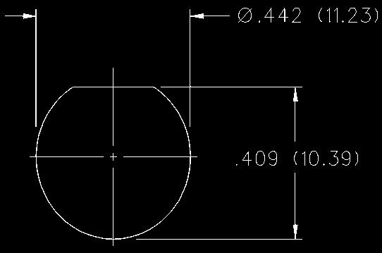
204 Mounting Hole Layouts Recommended Mounting Hole Dimensions Connectivity Solutions Tel: Fax:
205 Assembly Instructions / / / / / / / / Connectivity Solutions Tel: Fax:
206 Assembly Instructions / / / / / / CP CP CP CP-79-20BM CP-79-20BM CP-TNC BM CP CP CP CP CP CP CP CP CP-89-19BM CP-89-27BM CP-SW CP-SW CP-SW CP-SW CPF CPFI-UG CPFI-UG CPFI-UG CPFI-UG CPFI-UG CPFI-UG CPFI-UG CPFI-UG CPFI-UG CPL CPL CPL CPL CPL CPL CPL CPL CPM CPM-88-19A/S CPM CPM-TNC CPM-TNC CPMC CPMC CPMC CPMC CPMC CPMC CPMC CPMC CPMC CPMC CPMC CPMC CPMC CPMC CPMC CPMC CPMC CPMC CPMC CPMC CPMC CPMC CPMC CPMC CPMC CPMC CPMC CPMC CPMC CPMC-TNC CPMC-TNC CPMC-TNC CPMC-TNC CPMC-TNC CPN CPN CPN CPN-8/ CPN CPN CPN-142T CPN CPN CPN MINI-UHF MINI-UHF-1B MINI-UHF MINI-UHF MINI-UHF Connectivity Solutions Tel: Fax:
207 Assembly Instructions MMCX Right Angle Plug for.086 (2.18) Semi-Rigid Cable CABLE GROUP PART NO. RG-405/U (.086 Semi-Rigid) Identify piece parts. (2 piece parts) 2. Strip cable to dimensions shown. Do not nick center conductor. 3. Insert cable into body making certain that jacket bottoms on the connector body. Fixture cable and assembly to prevent movement during soldering. 4. Solder center conductor to contact as shown. Use a minimum amount of solder for a good joint. 5. Solder body to cable as shown. Use a minimum amount of heat to minimize cable insulation movement. 6. Press end cap into body access port using.156 (3.96) diameter flat punch or Johnson assembly tool Connectivity Solutions Tel: Fax:
208 Assembly Instructions MMCX Right Angle Plug for.047 (1.20) Diameter and RG-178 Size Flexible Cable with Crimp Insert CABLE GROUP PART NO. L CRIMP HEX.047 Flexible (3.56).105 (2.67) RG-178/U, (4.78).105 (2.67) 1. Identify piece parts. (3 piece parts) 2. Strip cable jacket to dimensions shown. Do not nick braid or center conductor during strip operations. 3. Slide crimp insert over braid and against jacket. Fold braid around crimp insert as shown. Strip cable dielectric to dimension shown. Tin center conductor. 4. Slide body assembly over cable and crimp insert, then seat firmly so cable dielectric butts against contact as shown. Crimp body using recommended crimp hex. Maintain forward pressure on cable while crimping. 5. Solder contact to center conductor through rear access port. Use a minimum amount of solder for a full fillet joint. 6. Press end cap into access port using.156 (3.96) diameter flat punch or Johnson assembly tool Connectivity Solutions Tel: Fax:
209 Assembly Instructions MMCX Right Angle Plug for RG-178, RG-316, RG-316 DS and RG-179 Size Flexible Cable CABLE GROUP PART NO. CRIMP HEX A B C RG-178, (2.67) RG-316/U, 188, 187, (3.25) RG-316 DS, 188 DS (3.83) Identify piece parts. (3 piece parts) 2. Strip cable jacket to dimensions shown. Do not nick braid or center conductor during strip operations. Tin center conductor. Slide crimp sleeve onto cable jacket. 3. Flair braid and assemble crimp stem of body subassembly under braid onto cable making certain that the cable center conductor enters contact slot as shown. Arrange braid uniformly around crimp stem. Slide crimp sleeve over braid and crimp securely using recommended crimp hex. 4. Solder center conductor to contact through rear access port. Use a minimum amount of solder for a full fillet joint. 5. Press end cap into body access port using.156 (3.96) diameter flat punch or Johnson assembly tool Connectivity Solutions Tel: Fax:
210 Assembly Instructions MMCX Straight Plug for.047 (1.19) Diameter and RG-178 Size Flexible Cable CABLE GROUP PART NO. L CRIMP HEX.047 Flexible (3.43).105 (2.67) x.250 (6.35) W RG-178/U, (4.67).105 (2.67) x.250 (6.35) W 1. Identify piece parts. (3 piece parts) 2. Strip cable jacket to dimensions shown. Do not nick braid or center conductor during strip operations. 3. Slide crimp insert over braid and against jacket, fold braid around crimp insert as shown. Strip dielectric to dimension shown. Tin center conductor if contact is to be soldered attached. Do not tin center conductor if contact is to be crimp attached. 4. Assemble contact assembly onto cable as shown. Solder attachment: Solder contact to center conductor. Care should be taken that excess solder is not applied. Crimp attachment: Crimp contact to center conductor using Johnson hand tool and die set Crimp location should be centered between end of contact and cross-hole. Crimp attachment to solid center conductor cables is not recommended. 5. Slide body assembly over contact and crimp insert, then seat firmly as shown. Crimp body using recommended crimp die hex. Maintain forward pressure on cable while crimping. 210 Connectivity Solutions Tel: Fax:
211 Assembly Instructions MMCX Straight Plug for RG-316, RG-179 and RG-316 DS Size Flexible Cable CABLE GROUP PART NO. CRIMP HEX RG-316/U, 188, 161, (3.25) RG-316 DS, 188 DS, 187 DS (3.83) RG-179/U, (3.25) 1. Identify connector parts. (3 piece parts) 2. Strip cable jacket to dimensions shown. Do not nick braid or center conductor during strip operations. Tin center conductor if contact will be solder attached. Do not tin center conductor if contact is to be crimp attached. Slide crimp sleeve onto cable jacket. 3. Assemble contact onto cable as shown. Solder attachment: Solder contact to center conductor. Care should be taken that excess solder is not applied. Crimp attachment: Crimp contact to center conductor using Johnson hand tool and die set Crimp location should be centered between end of contact and cross-hole. Crimp attachment to solid center conductor cables is not recommended. 4. Slide body assembly over contact and under braid, then seat firmly onto contact as shown. The body assembly will snap over the contact barb. The cable may have to be held in a soft jawed clamping fixture. Slide crimp sleeve forward and crimp using recommended crimp die hex. Connectivity Solutions Tel: Fax:
 RG-316 DS, 188 DS, 187 DS 135-3304-001.151 (3.83) RG-179/U, 187 135-3333-001.128 (3.25) 1. Identify connector parts. (3 piece parts) 2. Strip cable jacket to dimensions shown.")

212 Assembly Instructions MMCX Straight Jack for RG-316, RG-316 DS and RG-179 Size Flexible Cable CABLE GROUP PART NO. CRIMP HEX RG-316/U, 188, 161, (3.25) RG-316 DS, 188 DS, 187 DS (3.83) RG-179/U, (3.25) 1. Identify connector parts. (3 piece parts) 2. Strip cable jacket to dimensions shown. Do not nick braid or center conductor during strip operations. Tin center conductor if contact will be solder attached. Do not tin center conductor if contact is to be crimp attached. Slide crimp sleeve onto cable jacket. 3. Assemble contact onto cable. Solder attachment: Solder contact to center conductor. Care should be taken that excess solder is not applied. Crimp attachment: Crimp contact to center conductor using Johnson hand tool and die set Crimp location should be centered between end of contact and cross-hole. Crimp attachment to solid center conductor cables is not recommended. 4. Slide body assembly over contact and under braid, then seat firmly onto contact. The body assembly will snap over the contact barb. The cable may have to be held in a soft jawed clamping fixture. Slide crimp sleeve forward and crimp using recommended crimp die hex. 212 Connectivity Solutions Tel: Fax:
213 Assembly Instructions MMCX Straight Jack for.047 Diameter and RG-178 Size Flexible Cable CABLE GROUP PART NO. L CRIMP HEX.047 Flexible (3.43).105 (2.67) x.250 (6.35) W (3.43).105 (2.67) x.250 (6.35) W RG-178/U, (4.67).105 (2.67) x.250 (6.35) W (4.67).105 (2.67) x.250 (6.35) W 1. Identify connector parts. (3 piece parts except bulkhead jack as shown.) 2. Strip cable jacket to dimensions shown. Do not nick braid or center conductor during strip operations. 3. Slide crimp insert over braid and against jacket, fold braid around crimp insert. Strip dielectric to dimension shown. Tin center conductor if contact will be solder attached. Do not tin center conductor if contact is to be crimp attached. 4. Assemble contact assembly onto cable as shown. Solder attachment: Solder contact to center conductor. Care should be taken that excess solder is not applied. Crimp attachment: Crimp contact to center conductor using Johnson hand tool and die set Crimp location should be centered between end of contact and cross-hole. Crimp attachment to solid center conductor cables is not recommended. 5. Slide body assembly over contact and crimp insert, then seat firmly onto contact. Crimp body using recommended crimp hex. Bulkhead jack requires dieset. Maintain forward pressure on cable while crimping. Connectivity Solutions Tel: Fax:
214 Assembly Instructions MCX Solder Type Straight Plug for Semi-Rigid Cable CABLE TYPE PART NO. RG-405/U (.086 Semi-Rigid) Identify connector parts. (2 piece parts) 2. Strip cable to dimensions shown. Do not nick center conductor. 3. Place center contact on center conductor making sure contact bottoms against cable insulation. Solder center conductor to center contact through solder hole. Solder must not be allowed to run on outside of contact. Use a minimum amount of solder for a good joint..020 (0.51) diameter solder is recommended. Trim excess insulation. 4. Insert contact and cable into body assembly making sure cable is bottomed against insulator in body. Solder body to cable. Use a minimum amount of heat to minimize cable insulation movement. 214 Connectivity Solutions Tel: Fax:
215 Assembly Instructions MCX Solder Type Right Angle Plug for Semi-Rigid Cable CABLE GROUP PART NO. RG-405/U (.086 Semi-Rigid) Identify connector parts. (3 piece parts) 2. Strip cable to dimensions shown. Do not nick center conductor. 3. Insert cable into body making sure cable insulation bottoms on center contact. Solder center conductor to contact through the rear access port. Use a minimum amount of solder for a good joint..020 (0.51) diameter solder is recommended. 4. Solder body to cable. Use a minimum amount of heat to minimize cable insulation movement. Assemble insulator then place expansion cap in access port and seat with a.156 (3.96) diameter punch or hand tool Connectivity Solutions Tel: Fax:
216 Assembly Instructions MCX Crimp Type Straight Connectors for Flexible Cable CABLE GROUP PART NO. CRIMP HEX RG-178/U, / (2.67) / (2.67) RG-316/U, 161, / (3.25) 174, / (3.25) RG-316 DS, / (3.83) 188 DS / (3.83) RG-178/U, / (2.67) RG-316/U, 161, 174, / (3.25) RG-316 DS, 188 DS / (3.83) RG-179/U, / (3.25) RG-178/U, / (2.67) RG-316/U, 161, 174, / (3.25) RG-316 DS, 188 DS / (3.83) RG-178/U, / (2.67) RG-316/U, 161, 174, / (3.25) RG-316 DS, 188 DS / (3.83) RG-316/U, 188, (3.25) RG-316 DS, 188 DS (3.83) 1. Identify connector parts. (3 piece parts except bulkhead) 2. Strip cable to dimensions shown. Do not nick braid or center conductor. Tin center conductor if contact is to be solder attached. Do not tin center conductor if contact is to be crimp attached. Slide heat shrink (as applicable) and crimp sleeve onto jacket of cable. 3. Assemble contact onto cable as shown. Solder attachment. Solder contact to center conductor through solder hole using.020 (0.51) diameter solder. Use a minimum of solder for a good joint. Crimp attachment. Crimp contact to center conductor using a miniature 8 indent tool with positioner Crimp location should be centered between end of contact and cross hole. Crimp attachment to solid center conductor cable is not recommended. 4. Flair braid and slide body assembly over contact and under braid. Then seat body assembly firmly onto contact. (RG-178 is non-captivated, RG-316 incorporates snap-fit captivation.) The cable may have to be held in a clamping fixture. Arrange braid uniformly around crimp stem. Slide crimp sleeve forward and crimp using recommended crimp tool. Slide heat shrink forward and shrink (as applicable). 216 Connectivity Solutions Tel: Fax:
217 Assembly Instructions MCX Crimp Type Straight Connectors for Flexible Cable - 75 Ohm CABLE GROUP PART NO. CRIMP HEX RG (3.25) RG-179 DS (3.83) RG (3.25) RG-179 DS (3.83) RG (3.25) RG-179 DS (3.83) BELDEN 735A (3.83) 1. Identify connector parts. (2 piece parts except bulkhead) 2. Strip cable to dimensions shown. Do not nick braid or center conductor. A wire stripper of correct size is recommended for this step. Twist stranded center conductor into tight bundle and tin (optional). Slide crimp sleeve onto cable as shown. 3. Flare braid and slide cable into body making certain that the cable dielectric bottoms against center contact. Solder: Solder center conductor to contact through the side access ports and hole in center contact. Use a minimum amount of solder for a full fillet joint..015 (0.38) diameter solder is recommended. Crimp: Crimp Contact Attachment: Crimp contact using dieset in tool frame. 4. Arrange braid uniformly around crimp stem. Slide crimp sleeve over braid and access ports. Crimp securely using recommended hex size and crimp tool. Connectivity Solutions Tel: Fax:
218 Assembly Instructions MCX Crimp Type Right Angle Plugs for Flexible Cable - 50 Ohm CABLE PART CRIMP GROUP NO. A B C HEX RG-178/U, / (1.27).270 (6.86).200 (5.08).105 (2.67) RG-188/U, 316, 161, / (1.27).270 (6.86).200 (5.08).128 (3.25) RG-316 DS, 188 DS / (1.27).270 (6.86).200 (5.08).151 (3.83) RG-179/U, / (1.27).270 (6.86).200 (5.08).128 (3.25) RG-178/U, / (1.27).270 (6.86).200 (5.08).105 (2.67) RG-188/U, 316, 161, / (1.27).270 (6.86).200 (5.08).128 (3.25) RG-316 DS, 188 DS / (1.27).270 (6.86).200 (5.08).151 (3.83) RG-58/U, 303, / (1.70).295 (7.49).210 (5.33).213 (5.41) RG-316/U, 188, (1.27).270 (6.86).200 (5.08).128 (3.25) RG-316 DS, 188 DS (1.27).270 (6.86).200 (5.08).151 (3.83) 1. Identify connector parts. (4 piece parts except RG-58) 2. Strip cable to dimensions shown. Do not nick braid or center conductor. A wire stripper of correct size is recommended for this step. Twist stranded center conductor into tight bundle and tin (optional). Slide crimp sleeve onto cable shown. 3. Flair braid and slide cable into body making certain that the cable insulation bottoms on center contact. Arrange braid uniformly around crimp stem. Slide crimp sleeve over braid and crimp securely using recommended crimp tool. 4. Solder center conductor to contact through rear access port. Use a minimum amount of solder for a full fillet joint..020 (0.51) diameter solder is recommended. 5. Assemble insulator, if applicable; then place expansion cap in access port and seat with.156 (3.96) diameter flat punch or MCX hand assembly tool Shrink heat shrink tubing over crimp sleeve if applicable. 218 Connectivity Solutions Tel: Fax:
219 Assembly Instructions MCX Crimp Type Right Angle Plugs for Flexible Cable - 75 Ohm CABLE TYPE PART NO. CRIMP HEX RG (3.25) RG-179 DS (3.83) BELDEN 735A (3.83) 1. Identify connector parts (3-piece parts). 2. Strip cable to dimensions shown. Do not nick braid or center conductor. A wire stripper of correct size is recommended for this step. Twist stranded center conductor into tight bundle and tin (optional). Slide crimp sleeve onto cable as shown. 3. Flair braid and slide cable into body making certain that the cable dielectric bottoms on center contact. Arrange braid uniformly around crimp stem. Slide crimp sleeve over braid and crimp securely using recommended crimp tool. 4. Solder center conductor to contact through rear access port. Use a minimum amount of solder for a full fillet joint..020 (0.51) diameter solder is recommended. 5. Place expansion cap in access port and seat with.156 (3.96) diameter flat punch or MCX hand assembly tool Shrink heat shrink tubing over crimp sleeve if applicable. Connectivity Solutions Tel: Fax:
220 Assembly Instructions SMK Solder Type Straight Plugs for Semi-Rigid Cable BEAD Identify connector parts (5 piece parts) and tools (5 tools.) Strip cable jacket and dielectric to dimension shown. Place center contact onto center conductor. Slide contact soldering tool onto contact. Clamp the cable contact and tool into cable soldering vise and solder contact to center conductor. High temperature solder, such as 95/5 Sn/Ag is recommended so that contact solder joint remains stable during body soldering operation. Solder paste is recommended for the contact solder joint to minimize excess solder. The assembled contact dimension should be as shown. Remove excess solder from contact with a sharp blade and clean contact. Check for presence of excess solder by sliding body soldering tool over the contact. Remove soldering tool. Place connector nut and body on cable. Place connector body soldering tool over contact and thread the coupling nut and connector body firmly to the tool. Place cable subassembly into cable soldering vise. Clamp cable and soldering tool securely to insure the cable dielectric expansion will not disturb the cable in the vise during soldering. Place hot soldering iron on the connector body sleeve and apply solder from the opposite side. A low temp solder, such as 60/40 Sn/Pb is recommended for the body solder joint. Allow the soldered joint to cool and remove from fixture. Check contact location to the body. The best electrical results are achieved when the contact location is within a tolerance of.060 +/ Place bead onto neck portion of the tool. Thread Bead Assembly tool firmly into the coupling nut. Push the tool s plunger between your thumb and fingers to assemble the bead. Check bead location. Assemble seal ring onto body. BEAD ASSEMBLY TOOL RECESSION BEAD TO BODY PLUNGER TOOL / /002 (for.086 Semi-Rigid) (for.141 Semi-Rigid) Semi-Rigid Cable Vise Vise Stop Bead Assy. Tool Contact Soldering Tool Body Soldering Tool Cable Clamp Insert Connectivity Solutions Tel: Fax:
221 Assembly Instructions SMA Right Angle Solder Type Plug for Semi-Rigid Cable CABLE GROUP PART NO. A B RG-405/U (.086 Semi-Rigid) / (3.68).075 (1.90) RG-402/U (.141 Semi-Rigid) / (4.32).105 (2.67) 1. Identify connector parts. (2 piece parts) 2. Strip cable to dimensions shown. Do not nick center conductor during strip operations. 3. Insert cable into body making certain that the cable jacket is butted against internal body shoulder and cable dielectric is started into cross hole. Solder center conductor to contact using 60/40 tin/lead solder as shown. Use a minimum amount of solder for a good joint. 4. Solder body to cable using 60/40 tin/lead solder as shown. Use a minimum of heat to minimize cable dielectric growth. Any growth of cable dielectric shall be flush with contact. 5. Press end cap into body access port using.187 (4.75) dia. flat punch. Connectivity Solutions Tel: Fax:
222 Assembly Instructions SMA Solder Type Straight Jacks, Straight Plugs, and Straight Bulkhead Jacks for Semi-Rigid Cable CABLE GROUP PART NO. A RG-405/U (.086 Semi-Rigid) RG-402/U (.141 Semi-Rigid) / / (1.78) / / / / (2.16) / Identify connector parts. (2 piece parts) 2. Strip cable to dimensions shown. Do not nick center conductor. 3. Place center contact on center conductor making sure contact bottoms against cable insulation. Solder center conductor to center contact through solder hole. Solder must not be allowed to run on outside of contact. Use a minimum amount of solder for a good joint..020 (0.51) diameter solder is recommended. Trim excess insulation. 4. Insert contact and cable into body assembly making sure cable is bottomed against insulator in body. Solder body to cable. Use a minimum amount of heat to minimize cable insulation movement. 222 Connectivity Solutions Tel: Fax:
223 Assembly Instructions SMA Solder Type Straight Plugs for Semi-Rigid Cable CABLE GROUP PART NO. RG-402/U (.141 Semi-Rigid) Identify connector parts. (2 piece parts) 2. Strip cable to dimensions shown. Do not nick center conductor. Bevel the cable center conductor per contact detail of SMA interface on page 24. Slide coupling nut onto cable as shown. 3. Insert cable into body making sure cable jacket is flush with front of body. Solder body to cable. Use a minimum amount of heat to minimize cable insulation movement. Trim expanded insulation flush with front of body or fixture body and cable during soldering to prevent cable insulation expansion. 4. Thread coupling nut over body. Connectivity Solutions Tel: Fax:
224 Assembly Instructions SMA Solder Type Straight Plugs for Semi-Rigid Cable CABLE GROUP PART NO RG-402/U (.141 Semi-Rigid) Identify connector parts. (2 piece parts) 2. Strip cable to dimensions shown. Do not nick center conductor. Bevel the cable center conductor per contact detail of SMA interface on page 24. Slide coupling nut onto cable as shown. 3. Insert cable into body making sure cable jacket is bottomed against shoulder inside of body. Solder body to cable. Use a minimum amount of heat to minimize cable insulation movement. Trim expanded insulation flush with front of body or fixture body and cable during soldering to prevent insulation expansion. 4. Thread coupling nut over body. 224 Connectivity Solutions Tel: Fax:
225 Assembly Instructions SMA Solder Type Straight Plugs for Semi-Rigid Cable CABLE GROUP PART NO. RG-402/U (.141 Semi-Rigid) Identify connector parts. (3 piece parts) 2. Strip cable to dimensions shown. Do not nick center conductor. Bevel the cable center conductor per contact detail of SMA interface on page Insert cable into body making sure cable jacket is flush with front of body. Solder body to cable. Use a minimum amount of heat to minimize cable insulation movement. Trim expanded cable insulation flush with front of body or fixture body and cable during soldering to prevent insulation expansion. 4. Snap C spring onto connector body groove. Compress C spring using compression tool. Install coupling nut onto connector body. Nut should spin freely. Connectivity Solutions Tel: Fax:
226 Assembly Instructions SMA Solder Type Straight Plugs for Semi-Rigid Cable CABLE GROUP PART NO. A RG-405/U (1.78) (.086 Semi-Rigid) (1.78) RG-402/U (2.16) (.141 Semi-Rigid) (2.16) 1. Identify connector parts. (3 piece parts) 2. Strip cable to dimensions shown. Do not nick center conductor. Slide coupling nut onto cable as shown. 3. Place center contact on center conductor making sure contact bottoms against cable insulation. Solder center conductor to center contact through solder hole. Solder must not be allowed to run on outside of contact. Use a minimum amount of solder for a good joint..020 (0.51) diameter solder is recommended. Trim excess insulation. 4. Insert contact and cable into body making sure cable is bottomed against insulator in body. Solder body to cable. Use a minimum amount of heat to minimize cable insulation movement. 5. Thread coupling nut over body. 226 Connectivity Solutions Tel: Fax:
227 Assembly Instructions SMA Solder Type Antenna Connector Plug for Flexible or Semi-Rigid Cable CABLE GROUP PART NO. RG-178/U,.047 Semi-Rigid Identify connector parts. (2 piece parts) 2. Strip cable to dimensions shown. Do not nick center conductor or braid on flexible cable. FLEXIBLE CABLE RG-178, RG-196 SEMI-RIGID CABLE DIA..047 (1.19) 3. Flexible Cable Attachment: Twist stranded center conductor into tight bundle and tin (optional). Slide cable into body, making sure cable insulation bottoms on center contact and braid fits inside stem. Solder center conductor to contact through the side access ports. Use a minimum amount of solder for a good joint..020 (0.51) diameter solder is recommended. Solder braid to body. Use a minimum amount of solder to completely join the braid to the body. Semi-Rigid Cable Attachments: Slide cable into body making certain cable insulation bottoms on center contact. Solder center conductor to contact through the side access ports. Use a minimum amount of solder for a good joint..020 (0.51) diameter solder is recommended. Solder body to cable jacket. Use a minimum amount of heat to minimize cable insulation movement. Connectivity Solutions Tel: Fax:
228 Assembly Instructions SMA 3-Piece Plug, Jack and Bulkhead Jack for RG-178 Flexible Cable CABLE GROUP PART NO. CRIMP HEX (2.67) (2.67) RG-178/U, (2.67) (2.67) (2.67) (2.67) 1. Identify piece parts. (4 piece parts plus nut and washer for bulkhead.) 2. Strip cable jacket and braid to dimensions shown. Do not nick braid during strip operations. 3. Slide crimp insert over braid and against jacket. Fold braid around crimp insert as shown. Strip dielectric to dimension shown. If cable is being manually stripped the rear insulator can be assembled and used as a guide. Do not nick center conductor during strip operation. Tin center conductor if contact is to be solder attached. Do not tin center conductor if contact is to be crimp attached. 4. Assemble rear insulator over cable dielectric and contact over center conductor as shown. Solder attachment: Solder contact to center conductor using 60/40 tin/lead solder. Care should be taken that excess solder is not applied. Crimp attachment: Crimp contact to center conductor using production tooling or hand tool , setting #2 with positioner Crimp location should be centered between end of contact and x-hole. Crimp attachment to solid center conductor cables is not recommended. 5. Slide body assembly over contact, rear insulator and crimp insert. Crimp body using recommended crimp tool. Maintain forward pressure on cable while crimping. Body crimp die hex:.105 (2.67) hex 228 Connectivity Solutions Tel: Fax:
229 Assembly Instructions SMA Type Straight Plugs, Straight Jacks, and Straight Bulkhead Jacks for Flexible Cable - Crimp or Solder Contacts 1. Identify connector parts. (3 piece parts except bulkhead) 2. Strip cable to dimensions shown. Do not nick braid or center conductor. Tin center conductor if contact will be solder attached. Do not tin center conductor if contact is to be crimp attached. When stripping LMR-100 low loss cable, remove foil back to where cable jacket is stripped. A wire stripper of correct size is recommended for this step. Slide heat shrink (as applicable) and crimp sleeve onto jacket of cable. 3. Assemble contact onto cable as shown. Solder Attachment: Solder contact to center conductor through solder hole using.020 (0.51) diameter solder. Use a minimum amount of solder for a good joint. Crimp Attachment: Crimp contact to center conductor using Johnson Hand Tool , setting #2, with positioner Crimp location should be centered between end of contact and X-hole. Crimp attachment to solid center conductor cables is not recommended. 4. Flare braid and slide body assembly over contact and under braid. Then seat body assembly firmly onto contact. The cable may have to be held in a clamping fixture. Arrange braid uniformly around crimp stem. Slide crimp sleeve forward and crimp using recommended crimp tool. Slide heat shrink forward and shrink (as applicable). CABLE GROUP PART NO. A B CRIMP HEX RG-316/U, 161, / (5.46).278 (7.06).128 (3.25) 174, 188; LMR / (5.46).278 (7.06).128 (3.25) RG-316 DS, / (5.46).278 (7.06).151 (3.83) 188 DS / (5.46).278 (7.06).151 (3.83) RG-58/U, / (5.46).278 (7.06).213 (5.41) 141, / (5.46).278 (7.06).213 (5.41) RG-55/U, 142, / (5.46).278 (7.06).213 (5.41) 223, / (5.46).278 (7.06).213 (5.41) RG-179/U, / (5.46).278 (7.06).128 (3.25) / (5.46).278 (7.06).128 (3.25) RG-316/U, 161, 174, 188; LMR / (5.46).278 (7.06).128 (3.25) RG-316 DS, 188 DS / (5.46).278 (7.06).151 (3.83) RG-58/U, 141, / (5.46).278 (7.06) 213 (5.41) RG-55/U, 142, 223, / (5.46).278 (7.06).213 (5.41) RG-179/U, / (5.46).278 (7.06).128 (3.25) RG-316/U, 161, 174, 188; LMR / (7.11).715 (18.16).128 (3.25) RG-316 DS, 188 DS / (7.11).715 (18.16).151 (3.83) RG-58/U, 141, / (7.11).715 (18.16).213 (5.41) RG-55/U, 142, 223, / (7.11).715 (18.16).213 (5.41) RG-316/U, 161, 174, 188; LMR / (5.46).278 (7.06).128 (3.25) RG-316 DS, 188 DS / (5.46).278 (7.06).151 (3.83) RG-58/U, 141, / (5.46).278 (7.06).213 (5.41) RG-55/u, 142, 223, / (5.46).278 (7.06).213 (5.41) RG-316/U, 161, 174, 188; LMR / (5.46).278 (7.06).128 (3.25) RG-316 DS, 188 DS / (5.46).278 (7.06).151 (3.83) RG-58/U, 141, / (5.46).278 (7.06).213 (5.41) RG-55/U, 142, 223, / (5.46).278 (7.06).213 (5.41) RG-316/U, 161, 174, 188; LMR / (5.46).278 (7.06).128 (3.25) RG-316 DS, 188 DS / (5.46).278 (7.06).151 (3.83) RG-58/U, 141, / (5.46).278 (7.06).213 (5.41) RG-55/U, 142, 223, / (5.46).278 (7.06).213 (5.41) RG-316/U, 161, 174, 188; LMR / (5.46).278 (7.06).128 (3.25) RG-316 DS, 18 DS / (5.46).278 (7.06).151 (3.83) RG-58/U, 141, / (5.46).278 (7.06).213 (5.41) RG-55/U, 142, 223, / (5.46).278 (7.06).213 (5.41) RG-316/U, 161, 174, 188; LMR (5.46).278 (7.06).128 (3.25) RG-316 DS, 188 DS (5.46).278 (7.06).151 (3.83) RG-58/U, 141, (5.46).278 (7.06) 213 (5.41) Connectivity Solutions Tel: Fax:
230 Assembly Instructions Straight SMA Low Loss Diameter.195,.200 and.240 Straight Type Plugs CABLE GROUP PART NO. CRIMP HEX (5.41) LMR (5.41) (6.48) LMR (6.48) (5.41) LMR (5.41) (5.41) LMR (5.41) (6.48) LMR (6.48) (5.41) LMR (5.41) (6.48) LMR (6.48) (5.41) LMR (5.41) (5.41) LMR (5.41) (6.48) LMR (6.48) (5.41) LMR (5.41) (5.41) LMR (5.41) 1. Identify connector parts. (3 piece parts except bulkhead) 2. Strip cable to dimensions shown. Do not nick braid, foil or center conductor. Cut foil flush with dielectric, do not remove foil. Make sure that dielectric is clean and free from all particles. Tin center conductor, keeping solder amount to a minimum. Slide crimp sleeve onto jacket of cable. 3. Assemble contact onto cable as shown. Position contact such that a gap of no more than.020 (0.51) is kept between dielectric and contact. Solder contact to center conductor through solder hole using.020 (0.51) Diameter solder. Use a minimum amount of solder for a good joint. Do not allow contact to move into dielectric during soldering process. 4. Flare braid and slide body assembly over contact, foil and dielectric, then under braid. Seat body assembly firmly onto contact. Arrange braid uniformly around crimp stem. Slide crimp sleeve forward and crimp using Johnson hand crimp tool and recommended crimp die hex. 230 Connectivity Solutions Tel: Fax:
231 Assembly Instructions SMA Crimp Type Straight Plugs, Straight Jacks, and Straight Bulkhead Jacks for Flexible Cable CABLE GROUP PART NO. CRIMP HEX RG-178/U, (2.67) (2.67) RG-316/U, 161, (3.25) 174, (3.25) RG-316 DS, (3.83) 188 DS (3.83) RG-58/U, (5.41) 141, (5.41) RG-55/U, 142, (5.41) 223, (5.41) RG-316/U, 161, (3.25) 174, (3.25) 1. Identify connector parts. (6 piece parts except bulkhead) 2. Strip cable to dimensions shown. Do not nick braid or center conductor. A wire stripper of correct size is recommended for this step. Twist stranded center conductor into tight bundle and tin (optional). Slide crimp sleeve, nut and heat shrink tubing (as applicable) onto cable as shown. 3. Flare braid and slide cable into crimp stem. Place rear insulator and center contact over center conductor and position as shown for different cable sizes. Solder center conductor to contact through the solder hole. Solder must not be allowed to gather and run on outside of contact. Use a minimum amount of solder for a good joint..020 (0.51) diameter solder is recommended. 4. Arrange braid uniformly around crimp stem. Slide crimp sleeve over braid and crimp securely using recommended crimp tool. Slide center contact assembly into connector body. Thread coupling nut onto body and tighten to 10 in.-lb. torque. Slide heat shrink forward and shrink (as applicable). Connectivity Solutions Tel: Fax:
232 Assembly Instructions SMA Crimp Type Right Angle Plugs for Flexible Cable 1. Identify connector parts. (3 piece parts) 2. Strip cable to dimensions shown. Do not nick braid or center conductor. When stripping LMR-100 low loss cable, remove foil back to where cable jacket is stripped. A wire stripper of correct size is recommended for this step. Twist stranded center conductor into tight bundle and tin (optional). Slide crimp sleeve onto cable as shown. 3. Flare braid and slide cable into body making certain that the cable insulation bottoms on center contact. Solder center conductor to contact through the rear access port. Use a minimum amount of solder for a full fillet joint..020 (0.51) diameter solder is recommended. 4. Arrange braid uniformly around crimp stem. Slide crimp sleeve over braid and crimp securely using recommended crimp tool. Place expansion cap in access port and seat with.187 (4.75) diameter flat punch. Shrink heat shrink tubing over crimp sleeve if applicable. CABLE GROUP PART NO. CRIMP HEX RG-178/U, (2.67) (2.67) RG-316/U, 161, (3.25) 174, 188; LMR (3.25) RG-316 DS, (3.83) 188 DS (3.83) RG-58/U, (5.41) 141, (5.41) RG-55/U, 142, (5.41) 223, (5.41) RG-179/U, (3.25) (3.25) RG-316/U, 161, (3.25) 174, 188; LMR (3.25) RG-316 DS, (3.83) 188 DS (3.83) RG-58/U, (5.41) 141, (5.41) RG-55/U, 142, (5.41) 223, (5.41) RG-316/U, 161, (3.25) 174, 188; LMR (3.25) RG-316 DS, (3.83) 188 DS (3.83) RG-58/U, (5.41) 141, (5.41) RG-55/U, 142, (5.41) 223, (5.41) RG-316/U, 188, (3.25) RG-316 DS, 188 DS (3.83) RG-58/U, (5.41) 232 Connectivity Solutions Tel: Fax:
233 Assembly Instructions Right Angle SMA Low Loss Diameter.195,.200 and.240 CABLE GROUP PART NO. CRIMP HEX (5.41) LMR (5.41) (5.41) LMR (5.41) (6.48) LMR (6.48) (5.41) LMR (5.41) (5.41) LMR (5.41) (6.48) LMR (6.48) (5.41) LMR (5.41) (5.41) LMR (5.41) (6.48) LMR (6.48) 1. Identify connector parts. (3 piece parts) 2. Strip cable to dimensions shown. Do not nick braid, foil or center conductor. Cut foil flush with dielectric, do not remove foil. Make sure that dielectric is clean and free from all particles. Tin center conductor, keeping solder amount to a minimum. Slide crimp sleeve onto jacket of cable. 3. Flare braid and slide body assembly over foil and dielectric, then under braid. Make sure cable center conductor is contained within connector contact, but do not allow foil and dielectric to enter body access port. Solder center conductor to contact through the rear access port. Use a minimum amount of solder for a full fillet joint..020 (0.51) Diameter solder is recommended. 4. Arrange braid uniformly around crimp stem. Slide crimp sleeve forward and crimp using Johnson hand crimp tool and recommended crimp die hex. Place expansion cap in access port and seat with recommended Diameter flat punch. LOW LOSS DIA. A CRIMP DIE HEX FLAT PUNCH DIA (2.79).213 (5.41) hex.187 (4.75) (2.79).213 (5.41) hex.187 (4.75) (3.43).255 (6.48) hex.242 (6.15) Connectivity Solutions Tel: Fax:
234 Assembly Instructions SMA Clamp Type Straight Plugs, Straight Jacks, and Straight Bulkhead Jacks for Flexible Cable 1. Identify connector parts. (6 piece parts except bulkhead) 2. Strip cable to dimensions shown. Do not nick braid or center conductor. A wire stripper of correct size is recommended for this step. Twist stranded center conductor into tight bundle and tin (optional). Slide clamp nut and clamp cone onto cable as shown. Clamp cone must be oriented as shown for each size of cable. The RG-58/142 clamp cone slides over braid and against jacket. 3. Flare braid and slide cable into clamp stem. Place rear insulator and center contact over center conductor and position as shown for different cable sizes. Solder center conductor to contact through the solder hole. Solder must not be allowed to gather and run on outside of contact. Use a minimum amount of solder for a good joint..020 (0.51) diameter solder is recommended. CABLE GROUP PART NO. A B C RG-178/U, / (3.38).053 (1.35).085 (2.16) RG-161/U, 174, 188, / (3.38).053 (1.35).085 (2.16) RG-58/U, 141, / (5.72).145 (3.68) NONE RG-142, 223, 55, / (7.24).165 (4.19) NONE RG-178/U, / (3.38).053 (1.35).085 (2.16) RG-161/U, 174, 188, / (3.38).053 (1.35).085 (2.16) RG-58/U, 141, / (5.72).145 (3.68) NONE RG-142, 223, 55, / (7.24).165 (4.19) NONE 4. Arrange braid uniformly around clamp stem. Slide center contact assembly into body. Slide clamp nut against clamp cone and braid and tighten to 10 in.-lb. torque. 234 Connectivity Solutions Tel: Fax:
235 Assembly Instructions SMA Clamp Type Right Angle Plugs for Flexible Cable CABLE PART GROUP NO. A B C RG-178/U, (7.11).053 (1.35).085 (2.16) (7.11).053 (1.35).085 (2.16) RG-316/U, 161, (7.11).053 (1.35).085 (2.16) 174, (7.11).053 (1.35).085 (2.16) RG-58/U, (10.03).160 (4.06) None 141, (10.03).160 (4.06) None RG-55/U, 142, (10.67).180 (4.57) None 233, (10.67).180 (4.57) None 1. Identify connector parts. (4 piece parts) 2. Strip cable to dimensions shown. Do not nick braid or center conductor. A wire stripper of correct size is recommended for this step. Twist stranded center conductor into tight bundle and tin (optional). Slide clamp nut and clamp cone onto cable as shown. Clamp cone must be oriented as shown for each size of cable. The RG-58/142 clamp cone slides over braid and against jacket. 3. Flare braid and slide cable into body making certain that the cable insulation bottoms on center contact. Stepped down diameter of stem must slide under braid and jacket. Arrange braid uniformly around crimp stem. Slide clamp nut against clamp cone and braid and tighten to 10 in.-lb. torque. 4. Solder center conductor to contact through the rear access port. Use a minimum amount of solder for a full fillet joint..020 (0.51) diameter solder is recommended. Place expansion cap in access port and seat with.187 (4.75) diameter flat punch. Connectivity Solutions Tel: Fax:
236 Assembly Instructions SMB 3-Piece Straight Plugs CABLE GROUP PART NO. CRIMP HEX RG-316/U, 161, 174, 179, 187, / (3.25) RG-316 DS, 188 DS, 179 DS / (3.83) RG-58/U, 141, / (5.41) RG-179/U, / (3.25) RG-179 DS, 187 DS / (3.83) Belden 735A / (4.52) 1. Identify connector parts. (3 piece parts): Crimp sleeve, body assembly and contact 2. Strip cable to dimensions shown. Do not nick braid or center conductor. Tin center conductor if contact will be solder attached. Do not tin center conductor if contact is to be crimp attached. Slide heat shrink (as applicable) and crimp sleeve onto jacket of cable. 3. Assemble contact onto cable as shown. Solder Attachment: Solder contact to center conductor through solder hole using.015 (0.38) diameter solder. Use a minimum amount of solder for a good joint. Crimp Attachment: A miniature 8 indent crimp tool is recommended. Crimp location should be centered between end of contact and X-hole using positioner Crimp attachment to solid center conductor cables is not recommended. 4. Flare braid and slide body assembly over contact and under braid. Then seat body assembly firmly onto contact. The cable may have to be held in a clamping fixture. Arrange braid uniformly around crimp stem. Slide crimp sleeve forward and crimp using recommended crimp tool. Slide heat shrink forward and shrink (as applicable). 236 Connectivity Solutions Tel: Fax:
237 Assembly Instructions SMB/SMC Solder Type Straight Plugs and Jacks for Semi-Rigid Cable CABLE GROUP PART NO. L RG-405/U / (0.64) (.086 Semi-Rigid) / (0.64) RG-402/U (.141 Semi-Rigid) / (1.27) RG-405/U (.086 Semi-Rigid) / (0.64) 1. Identify connector parts. (2 piece parts except bulkhead) 2. Strip cable to dimensions shown. Do not nick center conductor. Slide cover sleeve onto cable as shown. 3. Insert cable into body making certain that the cable insulation bottoms on center contact. Solder center conductor to contact through the side access ports and hole in center contact. Use a minimum amount of solder for a good joint..020 (0.51) diameter solder is recommended. 4. Slide cover sleeve over access ports and solder body to cable and cover sleeve to body. Use a minimum amount of heat to minimize cable insulation movement. Connectivity Solutions Tel: Fax:
238 Assembly Instructions SMB/SMC Solder Type Right Angle Plugs for Semi-Rigid Cable CABLE GROUP PART NO RG-405/U (.086 Semi-Rigid) Identify connector parts. (2 piece parts - except diecast) 2. Strip cable to dimensions shown. Do not nick center conductor. 3. Insert cable into body making certain that the cable insulation bottoms on center contact. Solder center conductor to contact through the rear and side access ports. Use a minimum amount of solder for a good joint..020 (0.51) diameter solder is recommended. 4. Solder body to cable. Use a minimum amount of heat to minimize cable insulation movement. Place expansion cap in access port and set with.125 (3.17) diameter punch. Snap cover ring over side access port. 238 Connectivity Solutions Tel: Fax:
239 Assembly Instructions SMB/SMC/Mini-75 Ohm SMB (2-Piece) Crimp Type Straight Plugs, Jacks and Bulkhead Jacks for Flexible Cable CABLE PART CRIMP GROUP NO. HEX RG-316/U, 161, 174, 179, 187, / (3.25) RG-316 DS, 188 DS, 179 DS / (3.83) RG-178/U, / (2.67) RG-316/U, 161, / (3.25) 174, 179, 187, / (3.25) RG-179 DS, 187 DS, 188 DS, 316 DS / (3.83) RG-178/U, / (2.67) RG-316/U, 161, / (3.25) 174, 179, 187, / (3.25) RG-179 DS, 187 DS, / (3.25) 188 DS, 316 DS / (3.83) RG-58/U, 141, / (5.41) RG-316/U, 161, 174, / (3.25) RG-316 DS, 188 DS / (3.83) RG-179/U, / (3.25) RG-316/U, 161, 174, / (3.25) RG-316 DS, 188 DS / (3.83) RG-179/U, / (3.25) RG-179/U, 187, 316, 161, 174, / (3.25) RG-179 DS, 187 DS, 188DS, 316DS / (3.83) RG-179/U, 187, 316, / (3.25) 161, 174, / (3.25) RG-179 DS, 187 DS, / (3.83) 188 DS, 316 DS / (3.83) RG / (6.48) BELDEN 735A / (4.52) RG-316/U, 188, 174, 179, (3.25) RG-316 DS, 188 DS 179 DS, 187 DS (3.83) 1. Identify connector parts. (2 piece parts except bulkhead) 2. Strip cable to dimensions shown. Do not nick braid or center conductor. A wire stripper of correct size is recommended for this step. Twist stranded center conductor into tight bundle and tin. Slide crimp sleeve onto cable as shown. 3. Flare braid and slide cable into body making certain that the cable dielectric bottoms against center contact. Solder Attachment: Solder center conductor to contact through the side access ports and hole in center contact. Use a minimum amount of solder for a full fillet joint..020 (0.51) diameter solder is recommended. Crimp Attachment: Crimp applicable 50 Ohm connector contacts with dieset in tool frame. Crimp 75 Ohm connector contacts with dieset in tool frame. Crimp attachment to solid center conductor cables is not recommended. Connectivity Solutions Tel: Fax:
240 Assembly Instructions SMB/SMC/Mini-75 Ohm SMB Crimp Type Right Angle Plugs and Right Angle Bulkhead Jacks for Flexible Cable 1. Identify connector parts. (4 piece parts: crimp sleeve, body assembly, expansion cap and covering ring. Die cast body only.) 2. Strip cable to dimensions shown. Do not nick braid or center conductor. A wire stripper of correct size is recommended for this step. Twist stranded center conductor into tight bundle and tin (optional). Slide crimp sleeve onto cable as shown. 3. Flare braid and slide cable into body assembly making certain that the cable insulation bottoms on center contact. Arrange braid uniformly around crimp stem of body assembly. Slide crimp sleeve over braid and crimp securely using recommended crimp tool. 4. Solder center conductor to contact through the rear and side access ports. Use a minimum amount of solder for a good joint..020 (0.51) diameter solder is recommended. Place expansion cap in access port and seat with a.125 (3.17) diameter flat punch. Snap cover ring over side access port if applicable. CABLE PART CRIMP GROUP NO. A B HEX RG-178/U, / (5.56).312 (7.92).105 (2.67) RG-316/U, 161, 174, 179, 187, / (5.56).312 (7.92).128 (3.25) RG-179 DS, 187 DS, 188DS, 316 DS / (5.56).312 (7.92).151 (3.83) RG-316/U, 161, 174, 179, 187, / (5.56).312 (7.92).128 (3.25) RG-179 DS, 187 DS, 188 DS, 316 DS / (5.56).312 (7.92).151 (3.83) RG-178/U, / (4.50).289 (7.34).105 (2.67) RG-316/U, 161, 174, 179, 187, / (4.50).289 (7.34).128 (3.25) RG-179 DS, 187 DS, 188 DS, 316 DS / (4.50).289 (7.34).151 (3.83) RG-58/U, 141, / (5.56).289 (7.34).213 (5.41) RG-316/U, 161, 174, / (5.56).312 (7.92).128 (3.25) 316 DS, 188 DS / (5.56).312 (7.92).151 (3.83) RG-179/U, / (5.56).312 (7.92).151 (3.83) RG-179/U, 187, 316, / (4.50).289 (7.34).128 (3.25) 161, 174, / (5.56).312 (7.92).128 (3.25) RG-179 DS, 187 DS / (4.50).289 (7.34).151 (3.83) 316 DS, 188 DS / (5.56).312 (7.92).151 (3.83) RG / (5.56).289 (7.34).255 (6.48) BELDEN 735A / (4.50).289 (7.34).178 (4.52) RG-316/U, 188, , / (4.50).289 (7.34).128 (3.25) RG-316 DS, 188 DS 179 DS, 187 DS / (4.50) 2.89 (7.34).151 (3.83) 240 Connectivity Solutions Tel: Fax:
241 Assembly Instructions N Crimp Type Bulkhead Jack for Flexible Cable CABLE PART CRIMP GROUP NO. HEX RG-316/U, 161, 174, (4.06) RG-316 DS, 188 DS (4.06) RG-58/U, 141, (5.41) RG-55/U, 142, 223, (5.41) 1. Identify connector parts. (6 piece parts) 2. Strip cable to dimensions shown. Do not nick braid or center conductor. A wire stripper of correct size is recommended for this step. Twist stranded center conductor into a tight bundle and tin (optional). Slide crimp sleeve onto cable as shown. 3. Flare body and slide cable into crimp stem of rear body subassembly, until cable dielectric bottoms out on center contact. Solder center conductor to contact through the solder hole. Solder must not be allowed to gather and run on outside of contact. Use a minimum amount of solder for a good joint..020 (0.51) diameter solder is recommended. 4. Arrange braid uniformly around crimp stem. Slide crimp sleeve over braid and crimp securely using recommended crimp tool. Slide insulator over center conductor and slide center contact assembly into connector body. Thread rear body subassembly into body and tighten securely (ref. 30 in-lbs torque.) Connectivity Solutions Tel: Fax:
242 Assembly Instructions Crimp Type Straight Cable Termination for Flexible Cable CABLE GROUP PART NO. A CRIMP HEX RG-178/U, / (6.58).105 (2.67) RG-316/U, / (7.92).128 (3.25) 161, / (6.58).128 (3.25) 179, 187, / (6.58).128 (3.25) / (7.92).151 (3.83) RG-316 DS, 188 DS / (6.58).151 (3.83) / (6.58).151 (3.83) 1. Identify connector parts. (2 piece parts) 2. Strip cable to dimensions shown. Do not nick braid or center conductor. A wire stripper of correct size is recommended for this step. Twist stranded center conductor into tight bundle and tin. Slide crimp sleeve onto cable as shown. 3. Flare braid and slide cable into body making certain that the cable insulation is flush with bottom of connector. 4. Arrange braid uniformly around crimp stem. Slide crimp sleeve over braid and crimp securely using recommended crimp tool. 242 Connectivity Solutions Tel: Fax:
243 Assembly Instructions Crimp Type Right Angle Cable Termination for Flexible Cable CABLE GROUP PART NO. CRIMP HEX RG-316/U, 161, , 187, / (3.25) RG-316 DS, 188 DS / (3.83) 1. Identify connector parts. (2 piece parts) 2. Strip cable to dimensions shown. Do not nick braid or center conductor. A wire stripper of correct size is recommended for this step. Twist stranded center conductor into tight bundle and tin. Slide crimp sleeve onto cable as shown. 3. Flare braid and slide cable into body making certain that the cable insulation is flush with bottom of connector body. 4. Arrange braid uniformly around crimp stem. Slide crimp sleeve over braid and crimp securely using recommended crimp tool. Connectivity Solutions Tel: Fax:
244 Assembly Instructions Crimp Type Straight Cable Termination for End Launch CABLE GROUP PART NO. CRIMP HEX RG-178/U, (2.67) RG-316/U, 161, (3.25) 179, 187, (3.25) RG-316 DS, 188 DS, (3.84) 179 DS, 187 DS (3.84) RG-58/U, (5.41) 141, (5.41) RG-142/U, 55, (5.41) 223, (5.41) 1. Identify connector parts. (2 piece parts) 2. Strip cable to dimensions shown. Do not nick braid or center conductor. A wire stripper of correct size is recommended for this step. Twist stranded center conductor into tight bundle and tin. Slide crimp sleeve onto cable as shown. 3. Flare braid and slide cable into body making certain that the cable insulation is flush with bottom of connector body. 4. Arrange braid uniformly around crimp stem. Slide crimp sleeve over braid and crimp securely using recommended crimp tool. 244 Connectivity Solutions Tel: Fax:
245 Assembly Instructions Solder Type Straight Cable Termination for End Launch CABLE GROUP PART NO. RG-405/U (.086 Semi-Rigid) /806 RG-402/U (.141 Semi-Rigid) / Semi-Rigid / Identify connector parts. (1 piece part) 2. Strip cable to dimensions shown. Do not nick braid or center conductor. 3. Insert cable into body making sure cable is bottomed against shoulder body. Solder body to cable. Use a minimum amount of heat to minimize cable dielectric movement. Solder Type Straight Cable Termination for End Launch Surface Mount CABLE PART CRIMP GROUP NO. HEX RG-178/U, (2.67) 1. Identify connector parts (2-piece parts). 2. Strip cable to dimensions shown. Do not nick braid or center conductor. A wire stripper of correct size is recommended for this step. Twist stranded center conductor into tight bundle and tine. Slide crimp sleeve onto cable as shown. 3. Flare braid and slide cable into body making certain that the cable dielectric is flush with the end of the connector body. 4. Arrange braid uniformly around crimp sleeve. Slide crimp sleeve over braid and crimp securely using recommended crimp tool. Connectivity Solutions Tel: Fax:
246 Assembly Instructions BNC Straight 3-Piece Crimp Type Plugs for Flexible Cable STRIP DIMENSIONS CRIMP CONTACT RECOMMENDED PART NO. CABLE A B C SLEEVE HEX CRIMP HEX CRIMP TOOL CPMC-78-2 RG (8.00).248 (6.30).157 (4.00).255 (6.48).065 (1.65) P CPMC-78-5 BELDEN RG (8.00).248 (6.30).118 (3.00).288 (7.32).065 (1.65) P/24-318P CPMC RG-59 PLENUM.315 (8.00).248 (6.30).157 (4.00).213 (5.41).067 (1.70) P CPMC BELDEN 8218, 1855A.315 (8.00).248 (6.30).157 (4.00).184 (4.67).066 (1.68) P CPMC-88-1 RG (8.00).098 (2.50).157 (4.00).213 (5.41).067 (1.70) P CPMC-88-2 RG (8.00).118 (3.00).157 (4.00).258 (6.55).065 (1.65) P CPMC-88-3 BELDEN (8.00).118 (3.00).157 (4.00).310 (7.87).065 (1.65) P CPMC-88-5 RG (8.00).118 (3.00).157 (4.00).275 (6.98).065 (1.65) P CPMC RG-59 PLENUM.315 (8.00).118 (3.00).157 (4.00).213 (5.41).067 (1.70) P CPMC RG-58 PLENUM.344 (8.75).147 (3.75).157 (4.00).213 (5.41).067 (1.70) P CPMC RG-55, (8.00).118 (3.00).157 (4.00).213 (5.41).067 (1.70) P CPMC RG-180, 34M, (8.00).118 (3.00).157 (4.00).184 (4.67).066 (1.68) P CPMC RG-8X (MINI 8 ).315 (8.00).118 (3.00).157 (4.00).255 (6.48).065 (1.65) P CPMC BELDEN (8.00).118 (3.00).157 (4.00).184 (4.67).066 (1.68) P CPMC RG-174, 188, (8.75).118 (3.00).157 (4.00).184 (4.67).066 (1.68) P CPMC RG (7.62).240 (6.10).365 (9.27).405 (10.29).080 (2.03) / Identify connector parts. (3 piece parts) 2. Strip cable to dimensions shown. Do not nick braid or center conductor. Tin center conductor if contact will be solder attached. Do not tin center conductor if contact is to be crimp attached. A wire stripper of correct size is recommended for this step. Slide heat shrink (as applicable) and crimp sleeve onto jacket of cable. 3. Assemble contact onto cable as shown. Solder Attachment: Solder contact to center conductor through hole using a minimum amount of solder for a good joint. Crimp Attachment (where applicable): Crimp contact to center conductor using recommended crimp hex. 4. Flare braid and slide body assembly over contact and under braid. Then seat body assembly firmly onto contact. The cable may have to be held in a clamping fixture. Arrange braid uniformly around crimp stem. Slide crimp sleeve forward and crimp using recommended crimp hex. Slide heat shrink forward and shrink (as applicable). 246 Connectivity Solutions Tel: Fax:
247 Assembly Instructions BNC, TNC Straight Crimp Type Plugs with Crimp Insert for Flexible Cable BODY CONTACT RECOMMENDED PART NO. CABLE STEM HEX CRIMP HEX CRIMP TOOL CPM RG-174, 188, (4.67).066 (1.68) P CPM-88-19A/S RG-174, (4.67).066 (1.68) P CPM RG-179, (4.67).066 (1.68) P CPM-TNC-19 RG-174, 188, (4.67).066 (1.68) P CPM-TNC-20 RG-179, (4.67).066 (1.68) P 1. Identify connector parts. (4 piece parts) 2. Slide crimp insert over cable and strip cable jacket to dimension shown. Do not nick braid or center conductor during strip operations. 3. Flair braid and fold back around crimp insert as shown. Strip cable insulation to dimension shown. Do not nick center conductor. 4. Place bushing and contact on the cable. Hold the assembly in place and crimp contact to cable center conductor using the appropriate crimp hex. 5. Slide body assembly over contact and other connector parts until a slight snap is felt, indicating the contact is in place. Crimp the body assembly in the location shown using the appropriate crimp hex. Connectivity Solutions Tel: Fax:
248 Assembly Instructions BNC Straight Crimp Type Plugs for Flexible Cable CRIMP STRAIN RELIEF RECOMMENDED PART NO. CABLE SLEEVE HEX CRIMP HEX CRIMP TOOL CPMC RG-58, RG-59 PLENUM.235 (5.97),.250 (6.35).210 (5.33) P/ P 1. Identify connector parts. (3 piece parts) 2. Trim the cable to the dimensions shown. Take care not to nick the center conductor or the braid. 3. Slide the crimp sleeve onto the cable, narrow end first. Solder the contact to the center conductor using the minimum amount necessary for a good joint, make sure that the contact is flush with the insulation of the cable. Flare the braid. 4. Slide the body over the contact and under the braid. Then seat the body firmly onto the contact. 5. Arrange the braid uniformly around the crimp stem of the body. Slide the crimp sleeve forward and crimp using the recommended crimp hex. 248 Connectivity Solutions Tel: Fax:
249 Assembly Instructions BNC Straight Crimp Type Bulkhead Jacks for Flexible Cable STRIP DIMENSIONS CRIMP CONTACT RECOMMENDED PART NO. CABLE A B C SLEEVE HEX CRIMP HEX CRIMP TOOL CP-79-20BM1 RG (8.00).197 (5.00).138 (3.50).184 (4.67).066 (1.69) P CP-79-20BM2 RG (8.00).157 (4.00).118 (3.00).184 (4.67).066 (1.69) P CP-89-19BM1 RG-174, (8.00).197 (5.00).138 (3.50).184 (4.67).066 (1.69) P CP-89-27BM2 RG-178, (5.75).106 (2.70).118 (3.00).128 (3.25) None (solder P Only) 1. Identify connector parts. (3 piece parts) 2. Strip cable to dimensions shown. Do not nick braid or center conductor. Tin center conductor if contact will be solder attached. Do not tin center conductor if contact is to be crimp attached. A wire stripper of correct size is recommended for this step. Slide heat shrink (as applicable) and crimp sleeve onto jacket of cable. 3. Assemble contact onto cable as shown. Solder Attachment: Solder contact to center conductor through hole using a minimum amount of solder for a good joint. Crimp Attachment (where applicable): Crimp contact to center conductor using recommended crimp hex. 4. Flare braid and slide body assembly over contact and under braid. Then seat body assembly firmly onto contact. The cable may have to be held in a clamping fixture. Arrange braid uniformly around crimp stem. Slide crimp sleeve forward and crimp using recommended crimp hex. Slide heat shrink forward and shrink (as applicable). Connectivity Solutions Tel: Fax:
250 Assembly Instructions BNC Straight 2-Piece Crimp Type Plugs and Jacks for Flexible Cable PART CRIMP CRIMP RECOMMENDED NO. CABLE (BRAID HEX) (STRAIN RELIEF) CRIMP TOOL CP-78-2 RG-59, (8.13).250 (6.35) P CP-78-5 RG (8.13).275 (6.99) P/ P CP RG-59 PLENUM, RG (8.13).211 (5.36) P CP-88-1 RG (8.13).211 (5.36) P CP-88-2 RG-59, (8.13).250 (6.35) P CP-88-3 BELDEN (8.89).288 (7.32) P CP-88-4 RG-MATV (8.13).250 (6.35) P CP-88-5 RG (8.13).275 (6.90) P/ P CP RG-59 PLENUM, (8.13).211 (5.36) P CP-89-1 RG (8.13).211 (5.36) P CP-89-2 RG-59, (8.13).250 (6.35) P CP-SW88-2 RG-59, 62, RG-6 PLENUM.320 (8.13).250 (6.35) P CP-SW88-10 RG-59AU PLENUM.320 (8.13).211 (5.36) P CP-SW88-21 RG-58, RG-59 PLENUM.320 (8.13).211 (5.36) P CP-SW88-21 RG (8.13).250 (6.35) P 1. Identify connector parts. (2 piece parts) 2. Slide crimp sleeve over cable and strip cable jacket to dimension shown. Do not nick braid or center conductor during strip operations. 3. Flair braid and fold back. Strip cable insulation to dimension shown. Do not nick center conductor. Cables with stranded center conductors should be tinned for rigidity. 4. Insert center conductor into the guide hole found in the rear of the connector body. Push or twist the body onto the center conductor until the cable insulation butts up to the body. 5. Arrange braid uniformly around crimp stem. Slide crimp sleeve over braid and crimp securely using recommended crimp tool. 250 Connectivity Solutions Tel: Fax:
251 Assembly Instructions BNC Twist-on Plugs and Jacks Field Installable PART CABLE WIRE WIRE JACKET NO. TYPE GAUGE DECIMAL O.D. CPFI-UG78-2 RG-59, (0.64).220 (5.59)-.250 (6.35) CPFI-UG78-5 RG (1.02).270 (6.86)-.280 (6.35) CPFI-UG88-1 RG (0.81).185 (4.07)-.205 (5.21) CPFI-UG88-2 RG-59, (0.64).220 (5.59)-.250 (6.35) CPFI-UG88-3 BELDEN (0.81).272 (6.91)-.307 (7.80) CPFI-UG88-4 RG-MATV (0.81).220 (5.59)-.250 (6.35) CPFI-UG88-5 RG (1.02).270 (6.86)-.280 (7.11) CPFI-UG88-10 RG-TFE-59, (0.64).185 (4.07)-.205 (5.21) CPFI-UG89-2 RG-59, (0.64).220 (5.59)-.250 (6.35) CABLE ASSEMBLY CAUTIONS: Series are designed for solid center conductor wire. RG-58 cable will need the center conductor tin dipped (ONLY if it is not a solid center conductor). This is necessary to provide extra support for step 5. RG-MATV-59 cable will require caution when using the fingernail to rotate the braids on cable types that include aluminum foil for the outer conductor. DO NOT tear or rip the foil conductor to the 1/32" as suggested by step 3. RG-62 cable includes trimming the filament to 9/16" as well. Make sure that the filament does not unravel so that it protrudes past this dimension. 1. Identify connector parts. (1 piece) 2. Trim cable as shown. Taking care not to nick the center conductor or outer braid. 3. Use the fingernail to rotate the outer braids clockwise such that 1/32" of the insulation is bared. Then in the same direction rub the stray braids flat. (Stray or loose braids can cause shorts.) 4. Gently insert the center conductor down the back end of the connector, feeding it into the guide hole. (If the center conductor is not in place, approximately 1/8" of the center conductor the part closest to the dielectric will still be viewable.) 5. Firmly push the cable home (a slight clockwise twist may help with insertion). Then screw the connector on the cable in a clockwise direction until it is snugly attached to the jacket. Connectivity Solutions Tel: Fax:
252 Assembly Instructions BNC 75 Ohm Straight Cabled Plugs CRIMP CONTACT RECOMMENDED PART NO. CABLE TYPE SLEEVE HEX CRIMP HEX CRIMP TOOL CPMC-68-2 RG-59, 140, 302, Belden.255 (6.48).042 (1.07) P 9209A, 8279, 8241, 8263, Commscope 5563, Gepco VJ59U CPMC-68-3 Belden 8281, 9231, 9141,.324 (8.23).042 (1.07) P 728A, Commscope 7501, P VP618PVC CPMC-68-5 RG-6, Belden (8.89).042 (1.07) P CPMC Belden 82108, 89108,.255 (6.48).042 (1.07) P Coleman CPMC Belden (4.52).042 (1.07) P CPMC RG-179, 187,.128 (3.25).042 (1.07) P Belden 1520A CPMC Belden 735A, Commscope.178 (4.52).042 (1.07) P 735, Helex/Hitemp 735, BT3002, TZC75024 CPMC Belden 1855A, 720A.178 (4.52).042 (1.07) P Commscope 7538, Gepco VDM 230, VDM 250, Mini-75 CPMC Belden 1505A, 734A,.255 (6.48).042 (1.07) P Commscope 5565, Gepco VPM2000 CPMC Belden 1695A,.264 (6.71).042 (1.07) P Gepco VSD2001TS P CPMC Belden 1694A, 9248,.288 (7.32).042 (1.07) P Commscope 5765, Gepco VSD2001, Coleman CPMC Belden 1506A, 82259,.255 (6.48).042 (1.07) P 89259, Gepco VPM2000TK, VPM2000TS 1. Identify connector parts. (3 piece parts) 2. Slide crimp sleeve over the cable as shown. 3. Strip cable per dimensions given and loosen braid. 4. Place contact over cable center conductor and position against insulation. 5. Crimp (.042 crimp hex) or solder contact. If crimping the contact, crimp the contact as close as possible to the cable insulation as shown. 6. Push the cable with the attached contact into the connector body until contact is captured by internal rib within connector body. Contact location shall be per dimension shown. Slide crimp sleeve over braid until it rests against top of connector body. Finish assembly by crimping with appropriate crimp hex die as indicated for each connector by the table. 252 Connectivity Solutions Tel: Fax:
253 Assembly Instructions TNC Straight Crimp Type Plugs and Bulkhead Jacks for Flexible Cable STRIP DIMENSIONS CRIMP CONTACT RECOMMENDED PART NO. CABLE A B C SLEEVE HEX CRIMP HEX CRIMP TOOL CP-TNC BM RG-174, (8.51).197 (5.00).118 (3.00).184 (4.67).066 (1.69) P CPMC-TNC-1 RG (8.00).118 (3.00).157 (4.00).213 (5.41).067 (1.70) P CPMC-TNC-2 RG (8.00).118 (3.00).157 (4.00).255 (6.48).066 (1.68) P CPMC-TNC-13 RG-55, (8.00).118 (3.00).157 (4.00).213 (5.41).067 (1.70) P CPMC-TNC-16 Proflex RG (8.00).118 (3.00).157 (4.00).255 (6.48).066 (1.68) P CPMC-TNC-17 RG-8X.315 (8.00).118 (3.00).157 (4.00).255 (6.48).066 (1.68) P 1. Identify connector parts. (3 piece parts except bulkheads) 2. Strip cable to dimensions shown. Do not nick braid or center conductor. Tin center conductor if contact will be solder attached. Do not tin center conductor if contact is to be crimp attached. A wire stripper of correct size is recommended for this step. Slide heat shrink (as applicable) and crimp sleeve onto jacket of cable. 3. Assemble contact onto cable as shown. Solder Attachment: Solder contact to center conductor through hole using a minimum amount of solder for a good joint. Crimp Attachment (where applicable): Crimp contact to center conductor using recommended crimp hex. 4. Flare braid and slide body assembly over contact and under braid. Then seat body assembly firmly onto contact. The cable may have to be held in a clamping fixture. Arrange braid uniformly around crimp stem. Slide crimp sleeve forward and crimp using recommended crimp hex. Slide heat shrink forward and shrink (as applicable). Connectivity Solutions Tel: Fax:
254 Assembly Instructions N Straight Crimp Type Plugs for Flexible Cable STRIP DIMENSIONS CRIMP CONTACT RECOMMENDED PART NO. CABLE A B C SLEEVE HEX CRIMP HEX CRIMP TOOL CPN-68-1 RG (8.50).079 (2.00).157 (4.00).215 (5.46).065 (1.65) P CPN RG (8.50).079 (2.00).157 (4.00).215 (5.46).065 (1.65) P CPN-68-8 RG-8, (9.00).138 (3.50).157 (4.00).429 (10.90).100 (2.54) Identify connector parts. (3 piece parts except bulkheads) 2. Strip cable to dimensions shown. Do not nick braid or center conductor. Tin center conductor if contact will be solder attached. Do not tin center conductor if contact is to be crimp attached. A wire stripper of correct size is recommended for this step. Slide heat shrink (as applicable) and crimp sleeve onto jacket of cable. 3. Assemble contact onto cable as shown. Solder Attachment: Solder contact to center conductor through hole using a minimum amount of solder for a good joint. Crimp Attachment (where applicable): Crimp contact to center conductor using recommended crimp hex. 4. Flare braid and slide body assembly over contact and under braid. Then seat body assembly firmly onto contact. The cable may have to be held in a clamping fixture. Arrange braid uniformly around crimp stem. Slide crimp sleeve forward and crimp using recommended crimp hex. Slide heat shrink forward and shrink (as applicable). 254 Connectivity Solutions Tel: Fax:
255 Assembly Instructions N Crimp-Crimp Plugs for Flexible Cable PART CABLE WIRE WIRE JACKET HEX CONTACT RECOMMENDED NO. TYPE GAUGE DECIMAL O.D. SIZE CRIMP HEX CRIMP TOOL CPN-1 RG (1.09).185 (4.07)-.205 (5.21).213 (5.41).100 (2.54) CPN-2 RG (6.43).220 (5.59)-.250 (6.35).255 (6.48).100 (2.54) CPN-8 RG-8, (1.83).400 (10.16)-.410 (10.44).406 (10.31).102 (2.59) P CPN-8/110* RG-58 LOW LOSS, (2.80).400 (10.16)-.410 (10.44).406 (10.31).102 (2.59) P CPN-16 Proflex RG (1.42).220 (5.59)-.250 (6.35).255 (6.48).100 (2.54) CPN-17 RG-8X (1.65).220 (5.59)-.250 (6.35).255 (6.48).100 (2.54) CPN-142T RG-142TFE (0.86).200 (5.08)-.220 (5.59).213 (5.41).100 (2.54) Identify connector parts. (3 piece parts) 2. Strip cable to dimensions shown. Do not nick braid or center conductor. Slide the crimp sleeve onto the jacket; crimp narrow end first. 3. Crimp and solder the contact onto the center conductor using the recommended crimp hex or the minimum amount of solder for a good joint. Note: Contacts may need to be pre-fit onto the center conductor and soldered through the hole. 4. Flare the braid and slide the connector body over the contact and under the braid. Then seat the body FIRMLY onto the contact; the cable may need to be held in a clamping fixture. Arrange the braid uniformly around the crimp stem, then slide the crimp sleeve forward to the body and crimp the sleeve using the recommended crimp hex. * Cable Assembly Notes: The contact of the CPN-8/110 Connector fits RG-8 cable types with a center conductor diameter up to.110". Connectivity Solutions Tel: Fax:
256 Assembly Instructions Standard UHF Straight Crimp Type Plugs for Flexible Cable PART CABLE WIRE WIRE JACKET NO. GAUGE DECIMAL O.D. CPL RG (4.07)-.205 (5.21) CPL RG-59, (5.59)-.250 (6.35) CPL RG-58 COPHASE 2/20 2/.032 2/.185 (4.07)-.205 (5.21) CPL RG (10.06)-.410 (10.41) CPL RG-59 COPHASE 2/20 0/.025 2/.220 (5.59) CPL RG-59 PLENUM, RG (4.07)-.205 (5.21) CPL RG-8X (5.59)-.250 (6.35) CPL RG (4.07)-.205 (5.21) CRIMP CRIMP CONTACT RECOMMENDED (BRAID HEX) (STRAIN RELIEF) CRIMP HEX CRIMP TOOL.255 (6.48).213 (5.41).068 (1.73) P.255 (6.48) NONE.065 (1.65) P.255 (6.48) NONE NONE P.405 (10.29) NONE.110 (2.79) (11.44) NONE NONE P.235 (5.97) NONE.065 (1.65) P.255 (6.48) NONE NONE P.255 (6.48).213 (5.41).068 (1.73) P 1. Identify connector parts. (3 piece parts) Except CPL (1 piece) 2. Slide crimp sleeve over cable and strip cable to dimensions shown. Do not nick center conductor during strip operations. (CPL : Trim braid and insulation to.300 (7.62)). 3. Slide coupling nut onto the connector body. Then slide the connector body over cable so that the center conductor extends through the front of the contact. Crimp or solder the contact as shown. Trim away the center conductor extending past the contact. (CPL : Fold braid onto jacket before sliding connector body onto cable). 4. Arrange braid uniformly around crimp stem. Slide crimp sleeve over braid and crimp securely using recommended crimp tool. 256 Connectivity Solutions Tel: Fax:
257 Assembly Instructions Standard UHF Straight 2-Piece Crimp Type Jack for Flexible Cable PART NO. CABLE WIRE GAUGE WIRE DECIMAL JACKET O.D. CRIMP CRIMP RECOMMENDED (BRAID HEX) (STRAIN RELIEF) CRIMP TOOL CPF RG (0.83).185 (4.70)-.205 (5.21).320 (8.13).211 (5.36) P 1. Identify connector parts. (2 piece parts) 2. Slide crimp sleeve over cable and strip cable jacket to dimension shown. Do not nick braid or center conductor during strip operations. 3. Flair braid and fold back. Strip cable insulation to dimension shown. Do not nick center conductor. 4. Insert center conductor into the guide hole found in the rear of the connector body. Twist the body onto the center conductor until the cable insulation butts up to the body. 5. Arrange braid uniformly around crimp stem. Slide crimp sleeve over braid and crimp securely using recommended crimp tool. Connectivity Solutions Tel: Fax:
258 Assembly Instructions Mini-UHF Straight Crimp Type Plugs for Flexible Cable CONTACT BODY FERRULE CRIMP CONTACT RECOMMENDED PART NO. CABLE I.D. I.D. I.D. (BRAID HEX) CRIMP HEX CRIMP TOOL MINI-UHF-1 RG (1.11).126 (3.20).206 (5.23).210 (5.33).060 (1.52) P MINI-UHF-1B RG-58 Black.044 (1.11).126 (3.20).206 (5.23).210 (5.33).060 (1.52) P MINI-UHF-2 RG-59, (0.86).173 (4.40).261 (6.63).255 (6.48).060 (1.52) P MINI-UHF-16 RG-450, Proflex.055 (1.40).173 (4.40).261 (6.63).255 (6.48).060 (1.52) P MINI-UHF-17 RG-8X.065 (1.65).173 (4.40).261 (6.63).255 (6.48).060 (1.52) P 1. Identify connector parts. (4 piece parts) 2. Slide heat shrink (as applicable) and crimp sleeve onto jacket of cable. Strip cable to dimensions shown. Do not nick braid or center conductor. Tin center conductor if contact will be solder attached. Do not tin center conductor if contact is to be crimp attached. A wire stripper of correct size is recommended for this step. 3. Assemble contact onto cable as shown. Solder Attachment: Solder contact to center conductor through hole using a minimum amount of solder for a good joint. Crimp Attachment (where applicable): Crimp contact to center conductor using recommended crimp tool. 4. Slide coupling nut onto the connector body. 5. Flare braid and slide body assembly over contact and under braid as shown. Then seat body assembly firmly onto contact until a gentle snap is felt indicating the contact is in place. The cable may have to be held in a clamping fixture. Arrange braid uniformly around crimp stem. Slide crimp sleeve forward and crimp using recommended crimp tool. Slide heat shrink forward and shrink (as applicable). 258 Connectivity Solutions Tel: Fax:
259 Electronic Hardware Alphabetical Index Assembly Tools and Fixtures Banana Jacks Insulated Pierced Lug Terminal Insulated Rib-Loc Solder Terminal Insulated Solder Terminal Insulated Turret Terminal Uninsulated Rivet Panel Mount Uninsulated Standard Type Uninsulated Standard Type - Slotted Lug Banana Plugs Insulated Hex Body Solder Stud Insulated Hex Body Solder Type Long Handle Insulated Round Body Solderless Insulated Round Body Solder Stud Insulated Side Set Screw Solderless Insulated Solderless Tapered Handle Insulated Stacking Dual Type Insulated Stacking Single Type Uninsulated Panel Mount Screw Type, Beryllium Copper Spring Uninsulated Panel Mount Screw Type, Nickel Silver Spring Uninsulated Panel Mount Threaded Stud Uninsulated Rivet Type Banana Jacks & Plugs (Miniature) Insulated Rib-Loc Turret Terminal Insulated Solder Type Binding Posts Insulated Standard Insulated Standard With - Thumb Nut-Grounded Type Uninsulated Knurled Thumb - Nut-Grounded Type Test Jacks Horizontal Vertical Tip Jacks Insulated Deluxe Insulated Jack and Sleeve Assembly Insulated Metal Clad-Military Insulated Metal Clad-Standard Insulated Rib-Loc Insulated Standard Emerson Network Power Connectivity Solutions can meet your hardware specifications for design, delivery, and quality. Our network of distributors delivers products promptly from our comprehensive product line and helps fulfill your prototype needs. As a manufacturer, we can custom design and deliver any hardware you need. Ordering Information: For a numerical index of the complete electronic hardware product line, refer to page 289. Each product listing in this section includes detailed drawings and part numbering information. Material, mechanical, electrical and environmental specifications are listed for each item. To Order: When the part numbers you require have been identified, call us at , ext We will identify your local distributor who can very likely fill your order from inventory. Specials: For non-standard items, special applications or design engineering needs, call , ext Our experienced design engineering staff can customize any part or design a new part to meet your requirements. Complete model shop facilities are available for your prototyping needs. Tip Plugs.060 (1.50) Shrouded Insulated.080 (2.00) Solderless Insulated.080 (2.00) Standard Small Handle Connectivity Solutions Tel: Fax:


260 Horizontal Test Jacks Application Test Points Insulated Miniature SPECIFICATIONS Contact: Copper aluminum alloy* Finish: Silver Body: Nylon 6/6 per ASTM D4066 RATINGS Current: 5 amps Breakdown Voltage: 2100 VRMS minimum Contact Resistance: ohms maximum Adjacent Jack C: 1 pf maximum at 1 MHz SILVER PLATING PART NO. COLOR PART NO. COLOR White Yellow Red Blue Black Green Insulated Standard SPECIFICATIONS Contact: Copper aluminum alloy* Finish: Gold or Silver Body: Nylon 6/6 per ASTM D4066 RATINGS Current: 5 amps Breakdown Voltage: 2100 VRMS minimum Contact Resistance: Gold: ohms maximum Silver: ohms maximum Adjacent Jack C: 1 pf maximum at 1 MHz GOLD PLATING PART NO. COLOR PART NO. COLOR White Black Red Yellow SILVER PLATING PART NO. COLOR PART NO. COLOR White Yellow Red Brown Black Blue Green Violet Orange Gray For Standard Tip Plug:.080 (2.00) Diameter FEATURES: Contact protected from flux and solder Probe access from both ends Nylon UL approved for self extinguishing *A new material development that, for this application, meets or exceeds beryllium copper. For Standard Tip Plug:.080 (2.00) Diameter FEATURES: Contact protected from flux and solder Probe access from both ends or top Nylon UL approved for self extinguishing *A new material development that, for this application, meets or exceeds beryllium copper. Insulated Ruggedized: Military Type SPECIFICATIONS Contact: Copper aluminum alloy* Finish: Gold or Silver Body: Nylon 6/6 per ASTM D4066 RATINGS Current: 5 amps Breakdown Voltage: 2500 VRMS minimum Contact Resistance: Gold: ohms maximum GOLD PLATING Part No. to mil-spec. part no. cross reference PART NO. COLOR MIL-C-39024/ White Red Black Green Yellow -08 SILVER PLATING PART NO. COLOR PART NO. COLOR White Green Red Yellow Black For Standard Tip Plug:.080 (2.00) Diameter FEATURES: Contact protected from flux and solder Probe access from both ends Nylon UL approved for self extinguishing For Military or Industrial Applications * A new material development that, for this application, meets or exceeds beryllium copper. Avoid user injury due to misapplication. See safety advisory definitions inside front cover. 260 Connectivity Solutions Tel: Fax:
261 Vertical Test Jacks Application Test Points Insulated: Machined Contact SPECIFICATIONS: Contact: Beryllium copper per QQ-C-530 Finish: Silver Body: Nylon 6/6 per ASTM D4066 RATINGS Current: 5 amps Breakdown Voltage: 3500 VRMS minimum Contact Resistance: ohms maximum Adjacent Jack C: 1 pf maximum at 1 MHz SILVER PLATING PART NO. COLOR PART NO. COLOR White Orange Red Yellow Black Brown Green Blue For Standard Tip Plug:.080 (2.00) Diameter FEATURES: Contact protected from flux and solder Nylon UL approved for self extinguishing Insulated: Formed Contact SPECIFICATIONS: Contact: Beryllium copper per QQ-C-533 Finish: Gold or Silver Body: Nylon 6/6 per ASTM D4066 RATINGS Current: 5 amps Breakdown Voltage: 3500 VRMS minimum Contact Resistance: Silver: ohms maximum Adjacent Jack C: 1 pf maximum at 1 MHz SILVER PLATING PART NO. COLOR White Red Black Green Yellow For Standard Tip Plug:.080 (2.00) Diameter FEATURES: Spring loaded lead to hold in board Contact protected from flux and solder Nylon UL approved for self extinguishing Avoid user injury due to misapplication. See safety advisory definitions inside front cover. Connectivity Solutions Tel: Fax:
 RATINGS Current: 5 amps Breakdown Voltage: 3500 VRMS minimum Contact Resistance: 0.")

 Nylon UL approved for self extinguishing Avoid user injury due to misapplication. See safety advisory definitions inside front cover.")
 Panel Thickness: Up to.218 (5.")
262 Tip Jacks Application Connection to test equipment Power supplies Electrical instruments Insulated Standard: Rib-Loc Type SPECIFICATIONS Contact: Brass body per QQ-B-626D with wrap around beryllium copper spring per QQ-C-553 Finish: Silver Body: Nylon 6/6 per ASTM D4066 Panel Thickness: Up to.375 (9.05) RATINGS Current: 5 amps Breakdown Voltage: 3500 VRMS minimum Contact Resistance: ohms maximum Adjacent Jack C: 1 pf nominal SILVER PLATING PART NO. COLOR PART NO. COLOR White Green Red Yellow Black Blue For Standard Tip Plug:.080 (2.00) Diameter FEATURES: Machined contact with turret terminal Installs by pressing into mounting hole, no mounting hardware required Closed entry blocks access or probes greater than.085 (2.16) Nylon UL approved for self extinguishing Avoid user injury due to misapplication. See safety advisory definitions inside front cover. Insulated Metal Clad: Military Type SPECIFICATIONS Contact: Brass per QQ-B-626D with wrap around beryllium copper spring per QQ-C-533 Finish: Gold Body: Nylon 6/6 per ASTM D4066 Threaded Brass Jacket: Per QQ-B-626D, nickel plated Hardware: Nickel plated washer and nut (unassembled) Panel Thickness: Up to.218 (5.45) RATINGS Current: 10 amps Breakdown Voltage: 5700 VRMS minimum Contact Resistance: ohms maximum Contact-To-Panel C: 2 pf nominal Manufactured to meet MIL-C-39024/10 GOLD PLATING Part No. to MIL-spec. Part No. Cross Reference PART NO. COLOR MIL-C-39024/ White Red Black Green Blue -07 For Standard Tip Plug:.080 (2.00) Diameter FEATURES: Machined contact with turret terminal For military or industrial applications Closed entry blocks access of probes greater than.085 (2.16) Nylon UL approved for self extinguishing Avoid user injury due to misapplication. See safety advisory definitions inside front cover. 262 Connectivity Solutions Tel: Fax:
 RATINGS Current: 10 amps Breakdown Voltage: 5700 VRMS minimum Contact Resistance: 0.")
 Diameter FEATURES: Formed contact with slotted terminal Nylon UL approved for self extinguishing Avoid user injury due to misapplication. See safety advisory definitions inside front cover.")
 Body Thread Stripping Torque: 0.4 lb. in (4.5 kg. cm.) Panel Thickness: Up to.437 (11.10) RATINGS Current: 10 amps Breakdown Voltage: 5700 VRMS minimum Contact Resistance: 0.")

263 Tip Jacks Application Connection to test equipment Power supplies Electrical instruments Insulated Metal Clad: Standard Type SPECIFICATIONS Contact: Phosphor bronze per QQ-B-750 Finish: Silver Body: Nylon 6/6 per ASTM D4066 Threaded Brass Jacket: Per QQ-B-626D, nickel plated Panel Thickness: Up to.281 (7.10) RATINGS Current: 10 amps Breakdown Voltage: 5700 VRMS minimum Contact Resistance: ohms maximum Contact-To-Panel C: 2 pf nominal SILVER PLATING PART NO. COLOR White Red Black For Standard Tip Plug:.080 (2.00) Diameter FEATURES: Formed contact with slotted terminal Nylon UL approved for self extinguishing Avoid user injury due to misapplication. See safety advisory definitions inside front cover. Insulated Deluxe SPECIFICATIONS Contact: Brass per QQ-B-626D with wrap around beryllium copper spring per QQ-C-533 Finish: Silver Body: Nylon 6/6 per ASTM D4066 Hardware: Nickel plated nut (unassembled) Body Thread Stripping Torque: 0.4 lb. in (4.5 kg. cm.) Panel Thickness: Up to.437 (11.10) RATINGS Current: 10 amps Breakdown Voltage: 5700 VRMS minimum Contact Resistance: ohms maximum Contact-To-Panel C: 2 pf nominal SILVER PLATING PART NO. COLOR PART NO. COLOR White Green Red Yellow Black Blue For Standard Tip Plug:.080 (2.00) Diameter FEATURES: Machined contact with turret terminal Hex socket head.188 (4.77) for ease in mounting Closed entry blocks access of probes greater than.085 (2.16) Nylon UL approved for self extinguishing Avoid user injury due to misapplication. See safety advisory definitions inside front cover. Connectivity Solutions Tel: Fax:
 Body Thread Stripping Torque: 4.0 lb. in. (4.5 kg. cm.) Panel Thickness: Up to.437 (11.")


264 Tip Jacks Application Connection to test equipment Power supplies Electrical instruments Insulated Standard SPECIFICATIONS: Contact: Phosphor bronze per QQ-B-750 Finish: Bright tin Body: Nylon 6/6 per ASTM D4066 Hardware: Nickel plated nut (unassembled) Body Thread Stripping Torque: 4.0 lb. in. (4.5 kg. cm.) Panel Thickness: Up to.437 (11.10) RATINGS Current: 10 amps Breakdown Voltage: 5700 VRMS minimum Contact Resistance: ohms maximum Contact-To-Panel C: 2 pf nominal BRIGHT TIN PLATING PART NO. COLOR PART NO. COLOR White Green Red Yellow Black Blue For Standard Tip Plug:.080 (2.00) Diameter FEATURES: Formed contact with slotted terminal Hex socket head.188 (4.77) for ease in mounting Nylon UL approved for self extinguishing Avoid user injury due to misapplication. See safety advisory definitions inside front cover. Insulated Tip Jack and Sleeve Assembly SPECIFICATIONS Contact: Brass per QQ-B-626D with wrap around beryllium copper spring per QQ-C-533 Finish: Silver Body: Nylon 6/6 per ASTM D4066 Hardware: Nylon handle (assembled) Body Thread Stripping Torque: 4.0 lb. in. (4.5 kg.cm.) Panel Thickness: Up to.125 (3.20) RATINGS Current: 10 amps Breakdown Voltage: 5700 VRMS minimum Contact Resistance: ohms maximum Contact-To-Panel C: 2 pf nominal SILVER PLATING PART NO. COLOR White Red Black For Standard Tip Plug:.080 (2.00) Diameter FEATURES: Machined contact with turret terminal Includes deluxe tip jack X-001 For panel or line applications Hex socket head.188 (4.77) for ease in mounting Nylon UL approved for self extinguishing Avoid user injury due to misapplication. See safety advisory definitions inside front cover. 264 Connectivity Solutions Tel: Fax:
 Shrouded Tip Plug SPECIFICATIONS Contact and Nut: Brass per QQ-B-626D Finish: Gold or silver Body: Nylon 6/6 per ASTM D4066 Hardware: Nickel plated nut (unassembled) Body Thread Stripping Torque:")


265 Tip Plugs Application Connections to monitoring equipment.060 (1.50) Shrouded Tip Plug SPECIFICATIONS Contact and Nut: Brass per QQ-B-626D Finish: Gold or silver Body: Nylon 6/6 per ASTM D4066 Hardware: Nickel plated nut (unassembled) Body Thread Stripping Torque: 6 in. lb. (7 kg.cm.) Panel Thickness: Up to.343 (8.80) RATINGS Current: 7 amps Breakdown Voltage: 3500 VRMS minimum Contact Resistance: ohms maximum GOLD PLATING PART NO. COLOR PART NO. COLOR White Green Red Yellow Black Blue For Standard Tip Jack:.060 (1.50) Diameter FEATURES: Keyed mounting with double flats Shrouded Nylon UL approved for self extinguishing Avoid user injury due to misapplication. See safety advisory definitions inside front cover..080 (2.00) Insulated Standard: Small Handle (Solder or Crimp) SPECIFICATIONS Contact: Brass per QQ-B-626D Finish: Nickel Insulated Handle: Nylon 6/6 per ASTM D4066 RATINGS Current: 10 amps Breakdown Voltage: 3500 VRMS minimum Contact Resistance: ohms maximum NICKEL PLATING SOLDER TYPE UP TO CRIMP TYPE 16 GAUGE 16 GAUGE PART NO. COLOR White Red Black For Standard Test Jack:.080 (2.00) Diameter FEATURES: Solder or crimp type connection Accepts wire sizes up to 16 gauge Nylon UL approved for self extinguishing Designed for use with horizontal and vertical test jacks only See page xxx for crimp tool. Avoid user injury due to misapplication. See safety advisory definitions inside front cover..080 (2.00) Insulated: Solderless Type SPECIFICATIONS Contact: Brass per QQ-B-626D Finish: Nickel Insulated Handle: Nylon 6/6 per ASTM D4066 RATINGS Current: 10 amps Breakdown Voltage: 3500 VRMS minimum Contact Resistance: ohms maximum NICKEL PLATING PART NO. COLOR PART NO. COLOR White Green Red Blue Black For Standard Tip Jack:.080 (2.00) Diameter FEATURES: Recessed head to reduce shock hazard Accepts wire sizes up to 16 gauge Nylon UL approved for self extinguishing Avoid user injury due to misapplication. See safety advisory definitions inside front cover. Connectivity Solutions Tel: Fax:
.105 (2.67) For Standard Banana Plug:.")
 Across Flats FEATURES: Nickel plated brass body with cross hole Low cost, easy mounting banana jack Uninsulated Standard Type: Pierced Lug Terminal SPECIFICATIONS")
 RATINGS Current: 15 amps Contact Resistance: 0.010 ohms maximum NICKEL PLATING PART NO. 108-0740-001 For Standard Banana Plug:.")
266 Banana Jacks Application Test Equipment Power Supplies Uninsulated Rivet Panel Mount: Turret Terminal SPECIFICATIONS Jack Body: Brass per QQ-B-626D Finish: Nickel RATINGS Current: 15 amps Contact Resistance: ohms maximum NICKEL PLATING PART NO. PANEL THICKNESS A (1.6).105 (2.67) For Standard Banana Plug:.175 (4.44) Across Flats FEATURES: Nickel plated brass body with cross hole Low cost, easy mounting banana jack Uninsulated Standard Type: Pierced Lug Terminal SPECIFICATIONS Jack Body: Brass per QQ-B-626D Finish: Nickel Hardware: Nickel plated nut; stamped tin plated solder terminal (unassembled) Panel Thickness: Up to.375 (9.50) RATINGS Current: 15 amps Contact Resistance: ohms maximum NICKEL PLATING PART NO For Standard Banana Plug:.175 (4.44) Across Flats FEATURES: Accepts up to 12 gauge wire Hex head for faster installation For higher current designs 266 Connectivity Solutions Tel: Fax:
 Panel Thickness: Up to.250 (6.35) RATINGS Current: 15 amps Contact Resistance: 0.010 ohms maximum NICKEL PLATING PART NO.")
 Across Flats FEATURES: Accepts up to 12 gauge wire Hex head for faster installation For higher current designs Insulated Rib-Loc Solder Terminal SPECIFICATIONS Contact: Formed brass per QQ-B-626D")

 Body Thread Stripping Torque: 6.0 lb. in. (7kg. cm.) Panel Thickness: Up to.343 (8.")
 Across Flats FEATURES: Requires no mounting hardware Accepts up to 16 gauge wire Nylon UL approved for self extinguishing Avoid user injury due to misapplication.")
267 Banana Jacks Application Test Equipment Power Supplies Uninsulated Standard Type: Slotted Lug Terminal SPECIFICATIONS Jack Body: Brass per QQ-B-626D Finish: Nickel Hardware: Nickel plated nut; stamped tin plated solder terminal (unassembled) Panel Thickness: Up to.250 (6.35) RATINGS Current: 15 amps Contact Resistance: ohms maximum NICKEL PLATING PART NO For Standard Banana Plug:.175 (4.44) Across Flats FEATURES: Accepts up to 12 gauge wire Hex head for faster installation For higher current designs Insulated Rib-Loc Solder Terminal SPECIFICATIONS Contact: Formed brass per QQ-B-626D Finish: Bright tin Body: Nylon 6/6 per ASTM D4066 Panel Thickness: Up to.250 (6.35) RATINGS Current: 15 amps Breakdown Voltage: 7000 VRMS minimum Contact Resistance: ohms maximum Contact-To-Panel C: 2.4 pf nominal BRIGHT TIN PLATING PART NO. COLOR PART NO. COLOR White Green Red Yellow Black Blue Insulated Turret Terminal SPECIFICATIONS Contact: Machined brass per QQ-B-626D Finish: Silver Body: Nylon 6/6 per ASTM D4066 Hardware: Nickel plated nut (unassembled) Body Thread Stripping Torque: 6.0 lb. in. (7kg. cm.) Panel Thickness: Up to.343 (8.80) RATINGS Current: 15 amps Breakdown Voltage: 7000 VRMS minimum Contact Resistance: ohms maximum Contact-To-Panel: 2.4 pf nominal For Standard Banana Plug:.175 (4.44) Across Flats FEATURES: Requires no mounting hardware Accepts up to 16 gauge wire Nylon UL approved for self extinguishing Avoid user injury due to misapplication. See safety advisory definitions inside front cover. SLIVER PLATING PART NO. COLOR PART NO. COLOR Red Black For Standard Banana Plug:.175 (4.44) Across Flats FEATURES: Keyed mounting with double flats Nylon UL approved for self extinguishing Avoid user injury due to misapplication. See safety advisory definitions inside front cover. Connectivity Solutions Tel: Fax:
 Body Thread Stripping Torque: 6.0 lb. in. (7kg. cm.) Panel Thickness: Up to.343 (8.80) RATINGS Current: 15 amps Breakdown Voltage: 7000 VRMS minimum Contact Resistance: 0.")


268 Banana Jacks Application Test Equipment Power Supplies Insulated Solder Terminal SPECIFICATIONS Contact: Formed brass per QQ-B-626D Finish: Bright tin Body: Nylon 6/6 per ASTM D4066 Hardware: Nickel plated nut (unassembled) Body Thread Stripping Torque: 6.0 lb. in. (7kg. cm.) Panel Thickness: Up to.343 (8.80) RATINGS Current: 15 amps Breakdown Voltage: 7000 VRMS minimum Contact Resistance: ohms maximum Contact-To-Panel: 2.4 pf nominal BRIGHT TIN PLATING PART NO. COLOR PART NO. COLOR White Yellow Red Brown Black Blue Green Violet Orange Gray For Standard Banana Plug:.175 (4.44) Across Flats FEATURES: Keyed mounting with double flats Accepts up to 16 gauge wire Nylon UL approved for self extinguishing Avoid user injury due to misapplication. See safety advisory definitions inside front cover. Insulated Pierced Lug Terminal SPECIFICATIONS Contact: Brass per QQ-B-626D Finish: Nickel Hex Head: Molded phenolic Hardware: Nickel plated nut, fiber insulating washer and stamped tin plated solder terminal (unassembled) Panel Thickness: Up to.281 (7.15) RATINGS Current: 15 amps Breakdown Voltage: 1500 VRMS minimum Contact Resistance: ohms maximum Contact-To-Panel: 2.4 pf nominal NICKEL PLATING PART NO. COLOR Red Black For Standard Banana Plug:.175 (4.44) Across Flats FEATURES: Withstands extreme temperatures and abuse Stamped tin plated solder terminal with hole for up to 12 gauge wire Integrally molded hex head for fast installation Avoid user injury due to misapplication. See safety advisory definitions inside front cover. 268 Connectivity Solutions Tel: Fax:
 RATINGS Current: 15 amps Contact Resistance: 0.")
 Diameter FEATURES: Shorter spring adapts to standard jack or special size jack Ideal for limited space applications Uninsulated Panel")
.625 (16.")
 108-0750-002.750 (19.05) For Standard Banana Jack:.")
 Diameter FEATURES: Two stud lengths adapt to different panel sizes Pierced hole for up to 14 gauge wire Uninsulated Panel Mount Screw")

269 Banana Plugs Application Test Equipment Power Supplies Uninsulated Rivet Type SPECIFICATIONS Plug Body: Brass per QQ-B-626D Plug Spring: Beryllium copper per QQ-C-533 Finish: Silver Panel Thickness: Up to.156 (4.00) RATINGS Current: 15 amps Contact Resistance: ohms maximum SILVER PLATING PART NO For Standard Banana Jack:.166 (4.23) Diameter FEATURES: Shorter spring adapts to standard jack or special size jack Ideal for limited space applications Uninsulated Panel Mount Threaded Stud SPECIFICATIONS Plug Body: Brass per QQ-B-626D Plug Spring: Nickel silver per QQ-C-585 Finish: Nickel Panel Thickness: Up to.25 (6.35).625 (16.00) Hardware: Nickel plated nut, stamped tin plated solder terminal (unassembled) RATINGS Current: 15 amps Contact Resistance: ohms maximum C NICKEL PLATING PART NO. STUD LENGTH A (9.50) (19.05) For Standard Banana Jack:.166 (4.23) Diameter FEATURES: Two stud lengths adapt to different panel sizes Pierced hole for up to 14 gauge wire Uninsulated Panel Mount Screw Type, Nickel Silver Spring SPECIFICATIONS Plug Body: Brass per QQ-B-626D Plug Spring: Nickel silver per QQ-C-585 Finish: Silver Panel Thickness: Up to.125 (3.20) Hardware: Nickel plated screw, stamped tin plated solder terminal (unassembled) RATINGS Current: 15 amps Contact Resistance: ohms maximum C NICKEL PLATING PART NO For Standard Banana Jack:.166 (4.23) Diameter FEATURES: Rugged screw type Stamped tin plated solder terminal with hole for up to 14 gauge wire Connectivity Solutions Tel: Fax:
 Hardware: Nickel plated nut, stamped tin plated solder terminal (unassembled) RATINGS Current: 15 amps Contact Resistance: 0.")
270 Banana Plugs Application Test Equipment Power Supplies Uninsulated Panel Mount Screw Type Beryllium Copper Spring SPECIFICATIONS Plug Body: Brass per QQ-B-626D Plug Spring: Beryllium copper per QQ-C-533 Finish: Nickel Panel Thickness: Up to.156 (4.00) Hardware: Nickel plated nut, stamped tin plated solder terminal (unassembled) RATINGS Current: 15 amps Contact Resistance: ohms maximum NICKEL PLATING PART NO For Standard Banana Jack:.166 (4.23) Diameter FEATURES: Rugged screw type Stamped tin plated solder terminal with hole for up to 14 gauge wire Insulated Solderless Tapered Handle SPECIFICATIONS Plug Body: Brass per QQ-B-626D Plug Spring: Nickel silver per QQ-C-533 Finish: Nickel Insulated Handle: Nylon 6/6 per ASTM D4066 RATINGS Current: 15 amps Breakdown Voltage: 3500 VRMS minimum Contact Resistance: ohms maximum NICKEL PLATING PART NO. COLOR PART NO. COLOR White Yellow Red Brown Black Blue Green Violet Orange Gray For Standard Banana Jack:.166 (4.23) Diameter FEATURES: Fast solderless connection of up to 16 gauge wire Recessed plug body to limit shock hazard Nylon UL approved for self extinguishing Avoid user injury due to misapplication. See safety advisory definitions inside front cover. 270 Connectivity Solutions Tel: Fax:

 Diameter FEATURES: Solder type terminal uses up to 16 gauge wire Nylon UL approved for self extinguishing Avoid user injury due to misapplication.")
271 Banana Plugs Application Test Equipment Power Supplies Insulated Hex Body Solder Type Long Handle SPECIFICATIONS Plug Body: Brass per QQ-B-626D Plug Spring: Nickel silver per QQ-C-585 Finish: Nickel Insulated Handle: Nylon 6/6 per ASTM D4066 RATINGS Current: 15 amps Breakdown Voltage: 3500 VRMS minimum Contact Resistance: ohms maximum NICKEL PLATING PART NO. COLOR Black Red For Standard Banana Jack:.166 (4.23) Diameter FEATURES: Solder type terminal uses up to 16 gauge wire Nylon UL approved for self extinguishing Avoid user injury due to misapplication. See safety advisory definitions inside front cover. Insulated Side Set Screw Solderless SPECIFICATIONS Plug Body: Brass per QQ-B-626D Plug Spring: Nickel silver per QQ-C-585 Finish: Nickel Insulated Handle: Nylon 6/6 per ASTM D4066 RATINGS Current: 15 amps Breakdown Voltage: 35 VRMS minimum Contact Resistance: ohms maximum NICKEL PLATING PART NO. COLOR PART NO. COLOR Red Black For Standard Banana Jack:.166 (4.23) Diameter For Low Voltage (50 WVDC) Applications FEATURES: Fast solderless connection of up to 16 gauge wire Set screw for dependable connections with low voltage Nylon UL approved for self extinguishing Avoid user injury due to misapplication. See safety advisory definitions inside front cover. Connectivity Solutions Tel: Fax:

 Diameter FEATURES: Wire can be soldered to threaded stud Solder stud accepts up to 16 gauge wire Nylon UL approved for self extinguishing Avoid user injury due to misapplication.")
272 Banana Plugs Application Test Equipment Power Supplies Insulated Hex Body Solder Stud SPECIFICATIONS Plug Body: Brass per QQ-B-626D Plug Spring: Nickel silver per QQ-C-585 Finish: Nickel Insulated Handle: Nylon 6/6 per ASTM D4066 RATINGS Current: 15 amps Breakdown Voltage: 3500 VRMS minimum Contact Resistance: ohms maximum NICKEL PLATING PART NO. COLOR PART NO. COLOR Red Black For Standard Banana Jack:.166 (4.23) Diameter FEATURES: Wire can be soldered to threaded stud Solder stud accepts up to 16 gauge wire Nylon UL approved for self extinguishing Avoid user injury due to misapplication. See safety advisory definitions inside front cover. Insulated Round Body Solder Stud SPECIFICATIONS Plug Body: Brass per QQ-B-626D Plug Spring: Nickel silver per QQ-C-585 Finish: Nickel Insulated Handle: Nylon 6/6 per ASTM D4066 RATINGS Current: 15 amps Breakdown Voltage: 3500 VRMS minimum Contact Resistance: ohms maximum NICKEL PLATING PART NO. COLOR PART NO. COLOR Red Black For Standard Banana Jack:.166 (4.23) Diameter FEATURES: Wire can be soldered to threaded stud Solder stud accepts up to 16 gauge wire Nylon UL approved for self extinguishing Avoid user injury due to misapplication. See safety advisory definitions inside front cover. 272 Connectivity Solutions Tel: Fax:

 Diameter FEATURES: Wire locked in place by screwing down handle Accepts up to 16 gauge wire Nylon UL approved for self extinguishing Avoid user injury due to misapplication.")
273 Banana Plugs Application Test Equipment Power Supplies Insulated Round Body Solderless SPECIFICATIONS Plug Body: Brass per QQ-B-626D Plug Spring: Nickel silver per QQ-C-585 Finish: Nickel Insulated Handle: Nylon 6/6 per ASTM D4066 RATINGS Current: 15 amps Breakdown Voltage: 3500 VRMS minimum Contact Resistance: ohms maximum NICKEL PLATING PART NO. COLOR PART NO. COLOR Red Black For Standard Banana Jack:.166 (4.23) Diameter FEATURES: Wire locked in place by screwing down handle Accepts up to 16 gauge wire Nylon UL approved for self extinguishing Avoid user injury due to misapplication. See safety advisory definitions inside front cover. Insulated Stacking Single Type SPECIFICATIONS Plug Body: Brass per QQ-B-626D Plug Spring: Nickel silver per QQ-C-585 Finish: Nickel Insulated Handle: Nylon 6/6 per ASTM D4066 RATINGS Current: 15 amps Breakdown Voltage: 3500 VRMS minimum Contact Resistance: Ohm maximum NICKEL PLATING PART NO. COLOR PART NO. COLOR White Black Red Yellow For assembly tools see page 277. Avoid user injury due to misapplication. See safety advisory definitions inside front cover. For Standard Banana Jack:.166 (4.23) Diameter FEATURES: Built in strain relief for long life Solder stud accepts up to 16 gauge wire Accepts standard banana plug from rear Nylon UL approved for self extinguishing Connectivity Solutions Tel: Fax:

 PART NO. COLOR 108-0252-001 Red 108-0253-001 Black Avoid user injury due to misapplication. See safety advisory definitions inside front cover.")
274 Banana Plugs Application Test Equipment Power Supplies Insulated Stacking Dual Type SPECIFICATIONS Plug Body: Brass per QQ-B-626D Plug Spring: Nickel silver per QQ-C-586 Finish: Nickel Insulated Handle: Nylon 6/6 per ASTM D4066 RATINGS Current: 15 amps Breakdown Voltage: 3500 VRMS minimum Contact Resistance: ohms maximum For Standard Banana Jack:.166 (4.23) Diameter FEATURES: Accepts standard banana plug from rear Built-in strain relief for long life Nylon UL approved for self extinguishing NICKEL PLATING SET SCREW (Accepts wire sizes up to 14 gauge) PART NO. COLOR Red Black Avoid user injury due to misapplication. See safety advisory definitions inside front cover. 274 Connectivity Solutions Tel: Fax:
 RATINGS Current: 10 amps Breakdown Voltage: 3500 VRMS minimum Contact Resistance: 0.010 ohms maximum Contact-To-Panel C: 2.")
 Across Flats FEATURES: Hardwareless Rib-Loc mounting design Nylon UL approved for self extinguishing Avoid user injury due to misapplication. See safety advisory definitions inside front cover.")
275 Miniature Banana Jacks & Plugs Application Test equipment Insulated Rib-Loc Turret Terminal SPECIFICATIONS Contact: Brass per QQ-B-626D Finish: Silver Insulated Handle: Nylon 6/6 per ASTM D4066 Panel Thickness: Up to.313 (80) RATINGS Current: 10 amps Breakdown Voltage: 3500 VRMS minimum Contact Resistance: ohms maximum Contact-To-Panel C: 2.4 pf nominal Mounting Hole Options SILVER PLATING PART NO. COLOR PART NO. COLOR Red Black For Miniature Banana Plug:.120 (3.00) Across Flats FEATURES: Hardwareless Rib-Loc mounting design Nylon UL approved for self extinguishing Avoid user injury due to misapplication. See safety advisory definitions inside front cover. Insulated Solder Type SPECIFICATIONS Plug Body: Brass per QQ-B-626D Plug Spring: Beryllium copper per QQ-C-533 Finish: Nickel Insulated Handle: Nylon 6/6 per ASTM D4066 RATINGS Current: 10 amps Breakdown Voltage: 3500 VRMS minimum Contact Resistance: ohms maximum NICKEL PLATING PART NO. COLOR PART NO. COLOR Red Black For Miniature Banana Jack:. 104 (2.64) Diameter FEATURES: Small size for limited space Solder terminal accepts up to 18 gauge wire Nylon UL approved for self extinguishing Avoid user injury due to misapplication. See safety advisory definitions inside front cover. Connectivity Solutions Tel: Fax:
 Panel Thickness: Up to.281 (7.15) RATINGS Current: 15 amps NICKEL PLATING PART NO. 111-2223-001 For Standard Banana Plug:.175 (4.")
 diameter cross-hole accommodates up to 10 gauge wire Insulated Standard SPECIFICATIONS Stud: Brass per QQ-B-626D Finish: Silver Insulating Material: Nylon 6/6 per ASTM D4066 Hardware: Nickel")


 RATINGS Current: 15 amps NICKEL PLATING PART NO. COLOR PART NO. COLOR 111-0702-001 Red 111-0703-001 Black For Standard Banana Plug:.175 (4.")
276 Binding Posts Application Audio circuitry RF circuitry Uninsulated With Knurled Thumb - Nut-Grounded Type SPECIFICATIONS Stud: Brass per QQ-B-626D Finish: Nickel Hardware: Nickel plated nut (unassembled) Panel Thickness: Up to.281 (7.15) RATINGS Current: 15 amps NICKEL PLATING PART NO For Standard Banana Plug:.175 (4.44) Across Flats FEATURES: Nickel plated stud with serrated mounting surface prevents turning Captive thumb nut.110 (2.79) diameter cross-hole accommodates up to 10 gauge wire Insulated Standard SPECIFICATIONS Stud: Brass per QQ-B-626D Finish: Silver Insulating Material: Nylon 6/6 per ASTM D4066 Hardware: Nickel plated nut (unassembled) Body Thread Stripping Torque: 6.0 lb. in. (7.0 kg cm) Panel Thickness: Up to.281 (7.15) RATINGS Current: 15 amps Contact Resistance: ohms maximum Breakdown Voltage: 5700 VRMS minimum Stud-to-Panel: 3.3 pf nominal SILVER PLATING PART NO. COLOR PART NO. COLOR White Green Red Yellow Black Blue For Standard Banana Plug:.175 (4.44) Dia. FEATURES: Turret terminal Captive thumb nut Insulated body is flatted to prevent turning Nylon UL approved for self-extinguishing Insulated Standard With - Thumb Nut-Grounded Type SPECIFICATIONS Stud: Brass per QQ-B-626D Finish: Nickel Insulating Material: Nylon 6/6 per ASTM D4066 Hardware: Nickel plated nut (unassembled) Panel Thickness: Up to.313 (7.95) RATINGS Current: 15 amps NICKEL PLATING PART NO. COLOR PART NO. COLOR Red Black For Standard Banana Plug:.175 (4.44) Across Flats FEATURES: Serrated mounting surface prevents turning Captivated thumb nut.086 (2.18) accommodates up to 12 gauge wire Nylon UL approved for self-extinguishing Avoid user injury due to misapplication. See safety advisory definitions inside front cover. Avoid user injury due to misapplication. See safety advisory definitions inside front cover. 276 Connectivity Solutions Tel: Fax:

 For Insulated Standard Small Handle Tip Plugs:.080 (2.")

277 Assembly Tools and Fixtures Assembly Tools and Fixtures ( X-001 Series) For Standard Stacking Banana Plugs:.175 (4.44) Across Flats Quick and easy assembly of standard banana plug.175 (4.44) diameter is possible with the assembly tool and fixtures shown here. Strip wire jacket back 3/4 and feed wire through cross hole of metal contact. Fold stripped wire against metal plug body and slide insulated handle over banana plug body and wires. Insert contact wire into housing. Place into fixture. Push tip of tool into rear of contact. Snap contact into place. Handle of tool is curved to fit hand comfortably. Fixture and tip of tool made from tool steel. FIXTURE PART NO TOOL PART NO Crimp Tool ( X-XXX Series) For Insulated Standard Small Handle Tip Plugs:.080 (2.00) Diameter and.060 (1.50) Tip Jacks Quick and easy assembly of standard small handle tip plug.080 (2.00) diameter and.060 (1.50) tip jack is possible with the assembly tool shown. Set the selector to the appropriate wire size, strip wire to.180, insert wire and tip plug in tool, squeeze handles of the tool. A complete and accurate crimp is obtained each and every time, with no partial crimps. A ratchet insures a complete cycle of the tool. TOOL PART NO ASTRO TOOL PART NO MILITARY PART NO. M22520/1-01 Connectivity Solutions Tel: Fax:
278 Electronic Hardware Tube Sockets Tube Sockets Power Type Wafer Type Septar Type Johnson sockets are designed to provide secure retention of the tube and positive, low-resistance contact between the tube pins and socket contacts for our customers who use tubes for lack of a reliable high power RF semi-conductor. Ordering Information: For a numerical index of the complete electronic hardware product line, refer to page 289. Each product listing in this section includes mechanical drawings and part numbering information. Material, mechanical and electrical specifications are listed for each item. To Order: When you have determined the part number for the tube socket you require, contact one of our distributors for the socket you need. If you don t know the name of your local distributor or if you have special requirements, call Connectivity Solutions Tel: Fax:


279 Tube Sockets Power Tube Socket SPECIFICATIONS Housing: Brass per QQ-B-626D.0001" nickel plated Insulator: Glass base silicone Contacts: Beryllium copper (heat treated) per QQ-C-533,.0001" silver plated Power Type FEATURES: Raised pads for excellent base pin cooling For tubes such as RCA 8072, 8121 and 8122 Description: For ultra high frequency tubes. Also suitable for use with CRT tubes 1EP1 and 1EP11 with E.I.A. base no. E Base material has low dielectric constant which results in low pinto-pin and shunt capacity. Continuous heat resistance to 500 o F. Mounting lugs provide low inductance grounding. Three point mounting stability. Eleven pin configuration. PART NO (Industrial Grade) Giant: 5-Pin Configuration SPECIFICATIONS Base: L-423 steatite, DC-200 treated Contacts: Brass per QQ-B-626D, with steel springs per QQ-S-777,.0001" nickel plated Wafer Type FEATURES: Ventilating holes to provide tube seal cooling Sub-panel mounting possible with countersunk rivets and bossed mounting holes Description: Heavy duty steatite insulate wafer type socket. For tubes such as 4-125A, 4-250A, and RK-48 with E.I.A. base no. A5-19. Standard five pin configuration. PART NO (Commercial Grade) Connectivity Solutions Tel: Fax:


280 Tube Sockets 7-Pin Configuration SPECIFICATIONS Base: L-423 steatite, DC-200 treated Shell: Aluminum per QQ-A-200/8, iridated Contacts: Phosphor bronze per QQ-B-750, with beryllium copper springs per QQ-C-533,.0005" silver plated Septar Type FEATURES: Securely holds tube Positive, low resistance contact between tube pins and socket contacts Description: Designed for 7-pin tubes with E.I.A. base no. E7-2 such as the PART NO (Military Grade) 280 Connectivity Solutions Tel: Fax:
MCX - 75 Ohm Connectors
 133-8333-001 4 133-8333-401 4 133-8334-001 4 133-8334-401 4 133-8433-001 3 133-8433-101 3 133-8434-001 3 133-8445-001* 3 133-8445-101* 3 133-8701-201 5 133-8701-211 5 133-8701-301 6 133-8701-311 6 133-8701-401
SMA - 50 Ohm Connectors
 Alphabetical Index 142-0593-001 6 142-0593-006 6 142-0593-401 6 142-0593-406 6 142-0594-001 6 142-0594-006 6 142-0594-401 6 142-0594-406 6 142-0693-001 4 142-0693-006 4 142-0693-051 5 142-0693-056 5 142-0693-101
Non Magnetic Connectors
 Non Magnetic Connectors Johnson Components builds coaxial connectors using innovative materials and design to provide Mil Spec Performance at a commercial price. Now we offer our Non Magnetic Connectors
Non Magnetic Connectors Product Catalog
 Non Magnetic Connectors Product Catalog Introduction Johnson s Non-Magnetic Connector Additions Offer Solutions to MR Imaging Technology Johnson, a product line of Cinch Connectivity Solutions, has expanded
SMA One Piece Semi-Rigid Connectors
 SMA One Piece Semi-Rigid Connectors The Johnson captivated solderless contact connectors for semi-rigid cable provide a unique solution for high frequency cable assemblers. As compared to standard solder-on
Stainless Steel SMA Connectors Product Catalog
 Stainless Steel SMA Connectors Product Catalog Connectivity...for Stainless Steel SMA Connectors Connectivity...for Johnson Stainless Steel SMA Connectors meet or exceed the performance requirements of
Type "N" Connectors. Type "N" Interface Dimensions
 Type "N" Connectors The type N series coaxial connectors were originally designed as medium-size low voltage constant impedance 50 OHM connectors. Type N connectors found immediate popularity for microwave
bmam connectors DIVIDER PAGE
 bmam connectors DIVIDER PAGE 4 bmam interface dimensions "E" "D" REF. PLANE "E" REF. PLANE "G" "C".0 REF. 60 "C" "B" "B".0 REF. 0 "F" "D" male, plug INCHES / MILLIMETERS MINIMUM MAXIMUM LTR. IN. MM. IN.
Series SMPM-T. Description. Compatibility. Content. Interface dimensions (mm/inches) SMPM-T male (pin contact), smooth bore
 SMPM-T male (pin contact), smooth bore") Series Description The is the smallest threaded open source connector on the market. Its unique and innovative combination of a MIL- STD-348 SMPM female interface connector together with a retractable
Series Description The is the smallest threaded open source connector on the market. Its unique and innovative combination of a MIL- STD-348 SMPM female interface connector together with a retractable
SERIES BNC 50, COAXIAL MINIATURE CONNECTORS
 SERIES BNC 50, COAXIAL MINIATURE CONNECTORS DESCRIPTION CONTENTS PAGE HUBER+SUHNER BNC is still one of the most popular connector series, featuring a two stud bayonet coupling mechanism, which is particularly
Series MCX 50 micro miniature connectors
 Series MCX 50 micro miniature connectors Description Content MCX 50 HUBER+SUHNER MCX micro miniature snap-on connectors offer you an excellent blend of size,weight, durability and performance for applications
MCX Miniature Coaxial Connectors
 ONLINE CATALOG MCX Miniature Coaxial Connectors 104 John W. Murphy Drive P.O. Box 510 New Haven, CT 06513 www.aepconnectors.com e-mail: aepsales@aepconnectors.com Mating Interfaces MCX Miniature Coaxial
Amphenol RF Connectors
 Amphenol RF Connectors 007 901-9601 SMA PLUGS & ANGLE PLUGS FOR FLEXIBLE CABLE 50X IMPEDANCE Conn. Attachment RG-/U Outer Inner 901-9511-12SF Dbl. Braid RG-316 Plug Br. Solder $17.49 901-9531-12SF Angle
HN Connectors. Automatic Connector. Introduction. Contents. 631/ FAX 631/
 Connectors Introduction 2004 Automatic Connector. All rights reserved. pdf 1.0 4-13-04 Contents Specifications........................... 2 Straight Cable Plugs...................... 3 Right Angle Cable
Automatic Connector MHV Connectors MHV Introduction MHV series connectors Contents Polarized mating interfaces Anti-Rock mating interfaces
 Automatic s 2004 Automatic. All rights reserved. pdf 1.0 3-18-04 Contents Specifications........................... 2 Straight Cable Plugs...................... 3 Right Angle Cable Plugs...................
Series SK (2.92 mm) prec. submini. connectors
 prec. submini. connectors") Series prec. submini. connectors Description Content HUBER+SUHNER SK connectors are precision connectors for microwave applications up to 40 GHz. They are intermateable with series SMA and PC 3.5. They
Series prec. submini. connectors Description Content HUBER+SUHNER SK connectors are precision connectors for microwave applications up to 40 GHz. They are intermateable with series SMA and PC 3.5. They
SMP Connectors. Table of Contents PAGE. Introduction Specifications MountingHoles...7. Applications AssemblyTools...
 SMP Connectors Table of Content Connectivity for Table of Contents PAGE Introduction...3-4 Specifications...5-8 MountingHoles...7 Applications...9-12 AssemblyTools...13 AssemblyInstructions...14-18 CompetitorCrossReference...19
PERFORMANCE SPECIFICATION SHEET
 INCH-POUND 5 October 2016 SUPERSEDING w/amendment 2 July 2016 PERFORMANCE SPECIFICATION SHEET CONNECTORS, PLUG, ELECTRICAL, COAXIAL, RADIO FREQUENCY, SERIES SMA (CABLED) PIN CONTACT, RIGHT ANGLE, CLASS
Materials Connector part Material Finish
 Materials Connector part Material Finish Bodies Brass Nickel or Gold Center Contact Male: Brass Gold Female: Brass, Phosphor Bronze, or Beryllium Copper Insulator Delrin or Teflon N/A Crimp ferrule Annealed
TNC Connectors. RF Coax Connectors. Product Facts
 Product Facts Hex Crimp and Connectors 50 and 75 ohm commercial versions available Provides excellent performance at frequencies up to 7 GHz ow cost commercial type available type is smaller and lighter
SECTION 10 BNC / BNC 75 HDTV / BNC-TRX R141 / R142 / R266
 SECTION 10 10 BNC / BNC 75 HDTV / BNC-TRX R141 / R142 / R266 Contents Introduction... 10-4 to 10-5 Interfaces... 10-6 to 10-7 Characteristics... 10-8 to 10-11 Finder guide...10-12 to 10-13 COMPOSITE BNC
PERFORMANCE SPECIFICATION SHEET CONNECTORS, PLUGS, ELECTRICAL, COAXIAL, RADIO FREQUENCY (SERIES SMA (CABLED) - PLUG, PIN CONTACT, CLASS 2)
 - PLUG, PIN CONTACT, CLASS 2)") INCH-POUND MIL-PRF-39012/55G 6 February 2008 SUPERSEDING MIL-PRF-39012/55G 6 January 2006 PERFORMANCE SPECIFICATION SHEET CONNECTORS, PLUGS, ELECTRICAL, COAXIAL, RADIO FREQUENCY (SERIES SMA (CABLED) -
INCH-POUND MIL-PRF-39012/55G 6 February 2008 SUPERSEDING MIL-PRF-39012/55G 6 January 2006 PERFORMANCE SPECIFICATION SHEET CONNECTORS, PLUGS, ELECTRICAL, COAXIAL, RADIO FREQUENCY (SERIES SMA (CABLED) -
SECTION 9 BNC/BNC 75 HDTV/BNC-TRX R141/R142/R266 SIMPLIFICATION IS OUR INNOVATON. Visit for more information
 SECTION 9 BNC/BNC 75 HDTV/BNCTRX R141/R142/R266 SIMPLIFICATION IS OUR INNOVATON Visit www.radiall.com for more information Contents BNC Introduction... 94 to 95 Interfaces... 96 to 97 Characteristics...98
Materials Connector part Material Finish
 Materials Connector part Material Finish Bodies Brass Nickel or Gold Center Contact Male: Brass Gold Female: Brass, Phosphor Bronze, or Beryllium Copper Insulator Delrin or Teflon N/A Crimp ferrule Annealed
The Custom Interconnect Leader TM
 LC Series.5.188.685 ELECTRICAL Nominal Impedance: Frequency Range: Voltage Rating: Dielectric Withstanding Voltage: Insulation Resistance: VSWR: 50 ohms DC to 1.0 GHz 5,000 volts rms 3,000 volts rms 5,000
SUHNER QMA SUBMINIATURE CONNECTORS
 SUHNER QMA SUBMINIATURE CONNECTORS Description Content Page SUHNER QMA coaxial connectors are available with 50 Ω impedance. The frequency range extends to 11 GHz, depending on the connector and cable
Non-Magnetic Connectors Product Catalog
 Non-Magnetic Connectors Product Catalog Non-Magnetic RF Connectors Table of Contents PAGE Terms and Conditions............................3-4 Introduction......................................5 MMCX Non-Magnetic
INCH-POUND MIL-PRF-39012/28H w/amendment 4 25 January 2018 SUPERSEDING MIL-PRF-39012/28H w/amendment 3 15 April 2017
 INCH-POUND MIL-PRF-39012/28H 25 January 2018 SUPERSEDING MIL-PRF-39012/28H w/amendment 3 15 April 2017 PERFORMANCE SPECIFICATION SHEET CONNECTORS, RECEPTACLES, ELECTRICAL, COAXIAL, RADIO FREQUENCY, (SERIES
7RF Connectors. RF Connectors. Table of Contents
 RF Connectors Table of Contents Military Qualified Introduction.........................................................7003 N Series Connectors MIL-C-3902 50 Ohm.....................................................
PERFORMANCE SPECIFICATION SHEET CONNECTORS, PLUGS, ELECTRICAL, COAXIAL RADIO FREQUENCY, (SERIES BNC (CABLED), PIN CONTACT, CLASS 2)
, PIN CONTACT, CLASS 2)") INCH-POUND MIL-PRF-39012/16H 16 November 2006 SUPERSEDING MIL-PRF-39012/16G 26 September 1994 PERFORMANCE SPECIFICATION SHEET CONNECTORS, PLUGS, ELECTRICAL, COAXIAL RADIO FREQUENCY, (SERIES BNC (CABLED),
INCH-POUND MIL-PRF-39012/16H 16 November 2006 SUPERSEDING MIL-PRF-39012/16G 26 September 1994 PERFORMANCE SPECIFICATION SHEET CONNECTORS, PLUGS, ELECTRICAL, COAXIAL RADIO FREQUENCY, (SERIES BNC (CABLED),
Coaxial Cable Termination
 Coaxial Cable Termination RF one-step BNC/TNC connectors Applications RF one-step BNC/TNC connectors are single-piece assemblies for terminating the center conductor and the braid of a broad range of coaxial
PERFORMANCE SPECIFICATION SHEET CONNECTORS, PLUGS, ELECTRICAL, COAXIAL RADIO FREQUENCY, (SERIES TNC (CABLED), PIN CONTACT, RIGHT ANGLE, CLASS 2)
, PIN CONTACT, RIGHT ANGLE, CLASS 2)") INCH-POUND MIL-PRF-39012/30H 15 March 2018 SUPERSEDING MIL-PRF-39012/30H w/amendment 3 15 April 2017 PERFORMANCE SPECIFICATION SHEET CONNECTORS, PLUGS, ELECTRICAL, COAXIAL RADIO FREQUENCY, (SERIES TNC
INCH-POUND MIL-PRF-39012/30H 15 March 2018 SUPERSEDING MIL-PRF-39012/30H w/amendment 3 15 April 2017 PERFORMANCE SPECIFICATION SHEET CONNECTORS, PLUGS, ELECTRICAL, COAXIAL RADIO FREQUENCY, (SERIES TNC
INCH-POUND MIL-PRF-39012/29H w/amendment 3 25 January 2018 SUPERSEDING MIL-PRF-39012/29H w/amendment 2 21 November 2016
 INCH-POUND MIL-PRF-39012/29H 25 January 2018 SUPERSEDING MIL-PRF-39012/29H w/amendment 2 21 November 2016 PERFORMANCE SPECIFICATION SHEET CONNECTORS, RECEPTACLE, ELECTRICAL, COAXIAL, RADIO FREQUENCY, (SERIES
SERIES HPQN CONNECTORS
 SERIES HPQN CONNECTORS 1 DESCRIPTION Patented in 2008 by Anoison Electronics, the HPQN is a quick locking version of the widely used type N connector. By replacing the threaded interface of the original
PERFORMANCE SPECIFICATION SHEET CONNECTORS, PLUGS, ELECTRICAL, COAXIAL RADIO FREQUENCY, (SERIES BNC (CABLED), PIN CONTACT, CLASS 2)
, PIN CONTACT, CLASS 2)") PERFORMANCE SPECIFICATION SHEET MIL-PRF-39012/16H 03 January 2017 SUPERSEDING MIL-PRF-39012/16H w/amendment 1 20 April 2009 CONNECTORS, PLUGS, ELECTRICAL, COAXIAL RADIO FREQUENCY, (SERIES BNC (CABLED),
PERFORMANCE SPECIFICATION SHEET MIL-PRF-39012/16H 03 January 2017 SUPERSEDING MIL-PRF-39012/16H w/amendment 1 20 April 2009 CONNECTORS, PLUGS, ELECTRICAL, COAXIAL RADIO FREQUENCY, (SERIES BNC (CABLED),
HDRFI Series Tensolite High-Performance Cable & Interconnect Systems. High Density RF Interconnect
 HDRFI Series Tensolite High-Performance Cable & Interconnect Systems High Density RF Interconnect HDRFI is a patented Tensolite connection system that transfers high frequency signals through a unique
BNC / BNC 75 HDTV / BNC-TRX series R141 / R142 / R266
 10 BNC / BNC 75 HDTV / BNC-TRX series R141 / R142 / R266 CONTENTS Introduction... 10-4 to 10-5 Interfaces... 10-6 to 10-7 Characteristics... 10-8 to 10-11 Finder guide... 10-12 to 10-13 COMPOSITE BNC
Non-Magnetic Connectors Product Catalog
 Non-Magnetic Connectors Product Catalog Connectivity for Non-Magnetic RF Connectors Connectivity for Table of Contents PAGE TermsandConditions...3-4 Introduction...5 MMCX Non-Magnetic RF Connectors.....6-8
C Connectors. Automatic Connector. Introduction. Contents. C Interface Options. 631/ FAX 631/
 utomatic onnector onnectors Introduction 2004 utomatic onnector. ll rights reserved. pdf 1.0.1 3-23-04 ontents Specifications........................... 2 Straight Plugs...................... 3 Right ngle
8D with High Frequency Coaxial Contact
 8D Series M Coaxial Contacts 8D with High Frequency Coaxial Contact robust and powerfull coaxial High Frequency transmission (M) now available in any size 8 SOURIU insert of D38999 Series III. Spring HF
Jul03 Rev C EC
 Product Specification Coaxial BNC Solder Receptacle Connector 108-12079 10Jul03 Rev C EC 0990-0940-03 1. SCOPE 1.1. Content This specification covers the performance, tests and quality requirements for
RF CONNECTORS RFC SERIES
 Introduction: Adam Tech s RFC series RF connectors are a comprehensive assortment of Radio Frequency signal connectors in standard, miniature, sub-miniature, micro miniature and surface mount styles. Included
QMA and QN connectors, patented products, become some real standard for the RF Telecommunications industry.
 CONTENTS PAGE Introduction...4-5 Characteristics... 6 Plugs...7-9 Jacks...9- Receptacles...-4 Adapters...4-6 Protective cap... 6 Panel drilling... 7 Receptacles packaging... 8 Assembly instructions...9-30
RF CONNECTORS. Adam Technologies, Inc. ORDERING INFORMATION 1 01 D RoHS RFC SERIES INSULATOR A V A I L A B L E
 INTRODUCTION: Adam Tech s RFC series RF connectors are a comprehensive assortment of Radio Frequency signal connectors in standard, miniature, sub-miniature, micro miniature and surface mount style. Included
ENGINEERING COMMITTEE Interface Practices Subcommittee AMERICAN NATIONAL STANDARD ANSI/SCTE
 ENGINEERING COMMITTEE Interface Practices Subcommittee AMERICAN NATIONAL STANDARD ANSI/SCTE 176 2011 Specification for 75 ohm 'MCX' Connector, Male & Female Interface NOTICE The Society of Cable Telecommunications
Amphenol Telecom Solutions
 BNC 31 Series Bayonet Lock RF Connector System Materials Electrical Environmental Body/Finish /Nickel 50 ohm 75 ohm Temp. range -65 C thru 165 C Contact Frequency range 0-4GHz 0-10GHz Shock Consult Rep
SECTION 8 QUICK-LOCK: QMA/WQMA/QN/QRE R123/R123W/R164/R324 SIMPLIFICATION IS OUR INNOVATON. Visit for more information
 SECTION 8 QUICK-LOCK: QM/WQM/QN/QRE R123/R123W/R164/R324 SIMPLIFICTION IS OUR INNOVTON Visit www.radiall.com for more information Contents QM and WQM Introduction... 8-4 to 8-5 Characteristics... 8-6 to
WiFi Interface Identifier from RF Industries
 WiFi Interface Identifier from RF Industries Today s wireless market has exposed us to many new, and some familiar connectors. The wide range of antennas, access points, routers, WLAN s, cellular devices,
ULTIMATE SNAP-N-SEAL
 ULTIMATE SNAP-N-SEAL F Series Compression Connectors Thomas & Betts introduces the Ultimate Snap-N-Seal Compression Connector, the newest addition to the Snap-N-Seal system. Look for the classic design
CONNECTORS PRODUCTS RF CONNECTORS FIBER OPTIC PRODUCTS. Connector Products
 FIBER OPTIC PRODUCTS RF CONNECTORS Netrade is a leading global supplier of a wide variety of standard and custom RF coaxial connectors, cable assemblies and unique solutions for today's cutting edge applications,
.152 (3.86) KEYWAY DEPTH .033 (.84).066 (1.68) .550 DIA (13.97) MOUNTING SURFACE .350 (8.89) 3/8-32 UNEF-2A THREADS (19.71.
 KEYWAY DEPTH .033 (.84).066 (1.68) .550 DIA (13.97) MOUNTING SURFACE .350 (8.89) 3/8-32 UNEF-2A THREADS (19.71.") Optical SERIES 61K High Resolution, 4-Pin FEATURES 25, 32, 50, 64, 100, 128 and 256 Cycles per Revolution Available Sealed Version Available Rugged Construction Cable or Pin Versions 10 Million Rotational
Optical SERIES 61K High Resolution, 4-Pin FEATURES 25, 32, 50, 64, 100, 128 and 256 Cycles per Revolution Available Sealed Version Available Rugged Construction Cable or Pin Versions 10 Million Rotational
ATC 600S Series Ultra-Low ESR, High Q, NPO RF & Microwave Capacitors
 ATC 600S Series Ultra-Low ESR, High Q, NPO RF & Microwave Capacitors Features: Lowest ESR in Class Highest Working Voltage in class 250V Standard EIA Size: 0603 Laser Marking (Optional) RoHS Compliant
Low Loss RG 402 Equivalent
 421-671 Low Loss RG 402 Equivalent Section 10 Low Loss RG 402 Equivalent In applications that require the bendability of solid dielectric, but with the low loss that only a low density Teflon dielectric
PERFORMANCE SPECIFICATION SHEET
 INCH-POUND MIL-PRF-39012/2H 20 December 2016 SUPERSEDING MIL-PRF-39012/2H w/mendment 3 12 March 2012 PERFORMNCE SPECIFICTION SHEET CONNECTORS, PLUGS ND RECEPTCLES, ELECTRICL, COXIL, RDIO FREQUENCY, (SERIES
1.0/2.3 DIN 1.0/2.3 DIN 1.0/2.3 DIN. Technical Data. Microminiature Coaxial Connector. Material Data
 .0/.3 DIN.0/.3 DIN Microminiature Coaxial Connector Technical Data Description The.0/.3 series are through construction and materials especially suited for instruments, where highest reliability is required,
12G Broadcast connectors
 12G Broadcast connectors Delivering 12G in a single punch www.coax-connectors.com Welcome to COAX 12G BNC Plug return loss COAX Connectors Ltd is a leading UK designer, manufacturer and supplier of high
Lightweight SMT Miniature Coaxial Connectors 1.4 mm Mated Height
 Lightweight SMT Miniature Coaxial Connectors 1.4 mm Mated Height N.FL Series Mated height comparison (With U.FL-LP(V) ) Features 1. Low profile Nominal mated height is 1.4 mm (Max. 1.5 mm) 2. Small size:
ATC 600S Series Ultra-Low ESR, High Q, NPO RF & Microwave Capacitors
 ATC 600S Series Ultra-Low ESR, High Q, NPO RF & Microwave Capacitors Features: Lowest ESR in Class Highest Working Voltage in class 250V Standard EIA Size: 0603 Laser Marking (Optional) High Self Resonance
Ultra-Small Surface Mount Coaxial Connectors mm Mated Height
 All non- products have been discontinued, or will be discontinued soon. the products status on the Hirose website search at www.hirose-connectors.com, or contact your Hirose sales representative. NEW Ultra-Small
INTER SERIES ADAPTERS INTRODUCTION & 2.4 MM, 2.9 MM INTER SERIES
 INTRODUCTION & 2.4 MM, 2.9 MM INTER SERIES Inter series coaxial adapters are some of the more common components used in RF, microwave and wireless applications. OEM s and manufacturing and engineering
SURFACE MOUNT HIGH REPEATABILITY, BROADBAND TO-5 RELAYS DPDT
 SURFACE MOUNT HIGH REPEATABILITY, BROADBAND TO-5 RELAYS DPDT SERIES SGRF300 SGRF300D SGRF300DD SGRF303 SGRF303D SGRF303DD RELAY TYPE Repeatable, RF relay Repeatable, RF relay with internal diode for coil
75 Ohm N Male Connector Crimp/Solder Attachment for RG6
 75 Ohm N Male Connector Crimp/Solder Attachment for RG6 RF Connectors Technical Data Sheet PE4508 Configuration N Male Connector 75 Ohms Straight Body Geometry Features Max Operating Frequency 15 GHz Good
ZDC RF Coax Connector Series 50 & 75 Ohm
 CONTACTORS CONNECTORS WIRE & CABLE EMI/RFI FILTERS CIRCUIT BREAKERS HARNESSING & PROTECTION IDENTIFICATIO I/RFI FILTERS CIRCUIT BREAKERS HARNESSING & PROTECTION IDENTIFICATION & LABELING PCB & CABLE ASSEMBLIES
Ultra Small Surface Mount Coaxial Connectors 1.4mm Mated Height
 All non- products have been discontinued, or will be discontinued soon. Please check the products status on the Hirose website search at www.hirose-connectors.com, or contact your Hirose sales representative.
General Description. SC Configurations
 S onnectors General Description Delta S series connectors are medium-size, 50Ω impedance connectors with 11 16-24 threaded coupling and good power handling capability, particularly those connectors noted
Ultra Small Surface Mount Coaxial Connectors - Low Profile 1.9mm or 2.4mm Mated Height
 Ultra Small Surface Mount Coaxial Connectors - Low Profile 1.9mm or 2.mm Mated Height U.FL Series Up to 6GHz Transmission Speed Mated Height Comparison (With E.FL series) 1.9(2.0Max) U.FL-LP(V)-00 2.(2.5Max)
Reverse polarity connectors
 connectors Description According UL FCC (part 15.203) regulations, wireless radio equipment with removable antenna must not have a standardised interface. This to avoid the connection of antenna equipment
RF Characterization Report
 BNC7T-J-P-xx-ST-EMI BNC7T-J-P-xx-RD-BH1 BNC7T-J-P-xx-ST-TH1 BNC7T-J-P-xx-ST-TH2D BNC7T-J-P-xx-RA-BH2D Mated with: RF179-79SP1-74BJ1-0300 Description: 75 Ohm BNC Board Mount Jacks Samtec, Inc. 2005 All
Part Number (used with PRO-CRIMPER Tool Frame ) for 50 Ohm BNC Dual Crimp MIL Type Connectors
 for 50 Ohm BNC Dual Crimp MIL Type Connectors") Application Tooling Hand Tools CERTI-CRIMP Hand Tools are our top-of-the-line crimping tools featuring the original ratcheted crimp control. All tools are designed to exacting specifications, and manufactured
Application Tooling Hand Tools CERTI-CRIMP Hand Tools are our top-of-the-line crimping tools featuring the original ratcheted crimp control. All tools are designed to exacting specifications, and manufactured
Cambridge Connectors A division of Cambridge Electronic Industries Ltd
 TM Cambridge Connectors A division of Cambridge Electronic Industries Ltd Precision 75 ohm coaxial connectors for 3GHz digital broadcast and video applications including PCI Express and CoaXPress TM BNC
Interface RF Connector with Switch, built-in interlock, DC to 3GHz
 Interface RF Connector with Switch, built-in interlock, DC to 3Hz MS-151NB Series Overview Designed for end user applications requiring redirection of transmission from internal built-in antenna to the
EZ-MATE CONNECTORS The Complete Family of Multi-Channel Fiber Optic Connectors for Harsh Environment Deployable Systems
 The Complete Family of Multi-Channel Fiber Optic Connectors for Harsh Environment Deployable Systems Overview The OCC EZ-MATE family of hermaphroditic style fiber optic connectors provides the most comprehensive
SECTION 4 TABLE OF CONTENTS
 Contents Introduction LC, SC and ST Series...4-2 Markets and Applications...4-2 International Standard Documents Compliance...4-2 LC Series Features and Benefits...4-3 LC Standard... 4-4 to 4-5 LC for
Interface RF Connector with Switch
 NEW Interface RF Connector with Switch MS-5C Series Overview Designed for end user applications requiring redirection of the transmission. Small size, lightweight and high reliability make it ideal for
High Density BNC Connectors
 High Density BNC Connectors Spacing HD-BNCTM High Density Cable 8 mm (.315 ) 64 interconnects in 2.5 x 2.5 Standard Cable 9.5 mm (.374 ) 36 interconnects in 2.5 x 2.5 Standard BNC 15.9 mm (.625 ) 16 interconnects
Precision 75 ohm coaxial connectors for 3GHz digital broadcast and video applications including PCI Express and CoaXPress TM
 Precision 75 ohm coaxial connectors for 3GHz digital broadcast and video applications including PCI Express and CoaXPress TM BNC Connectors 1.0/2.3 Connectors Mini BNC Connectors Edgecard Connectors Contacts
Small Circular Connector. JN1W / JN2W Series
 COMPONENTS PRODUCT INFORMATION RoHS Compliant NEW Small Circular Connector / Series CONNECTOR MB-0178-5 December 2012 Angle Plug Cable Connecting Straight Plug Wall Mount Cable Connecting Waterproof Cap
Interface Connectors for Miniature, Portable Terminal Devices
 NEW Interface Connectors for Miniature, Portable Terminal Devices ST Series Strong locking mechanism Right Mating direction Left Top 9N max. Overview Developed as external input/output connectors for the
Small Circular Connector. JN1/JN2 Series. Dust Cap
 COMPONENTS PRODUCT INFORMATION RoHS Compliant NEW Small Circular Connector JN1/JN2 Series Angle Plug CONNECTOR MB-0054-8 October 2009 [JN1] [JN2] [JN1] [JN2] Straight Plug Cable Connecting Individual Plug
BNC 75 RF CONNECTORS. Simple steps to guide you in using this catalogue. Applications. Options. Ordering Codes BNC 75 RF CONNECTORS
 BNC 75 RF CONNCTORS BNC 75 RF CONNCTORS Amphenol offers a complete range of highperformance BNC plugs for use in digital/ HD video applications. Amphenol s True 75 Ohm BNC connectors perform well up to
ASSEMBLY, INSTALLATION, AND REMOVAL OF CONTACTS AND MODULES
 ASSEMBLY, INSTALLATION, AND REMOVAL OF CONTACTS AND MODULES FOR 75 OHM AND 75 OHM HD COAXIAL CONTACTS AND MODULES Table of Contents SECTION 1 RECEIVER CONTACT ASSEMBLY INSTRUCTIONS SECTION 2 ITA CONTACT
ENGINEERING COMMITTEE
 ENGINEERING COMMITTEE Interface Practices Subcommittee AMERICAN NATIONAL STANDARD ANSI/SCTE 01 2015 Specification for F Port, Female, Outdoor NOTICE The Society of Cable Telecommunications Engineers (SCTE)
APPLIANCES /// MTA, CST-100 II AND SL-156 CONNECTORS. CONNECTORS/ APPLIANCES MTA, CST-100 II and SL-156 Connectors
 PPLINCES /// MT, CST-100 II ND SL-156 CONNECTORS CONNECTORS/ PPLINCES MT, CST-100 II and SL-156 Connectors Contents Introduction This catalog has been designed to assist you, our customer, identify products
ENGINEERING COMMITTEE Interface Practices Subcommittee AMERICAN NATIONAL STANDARD ANSI/SCTE Specification for F Connector, Male, Pin Type
 ENGINEERING COMMITTEE Interface Practices Subcommittee AMERICAN NATIONAL STANDARD ANSI/SCTE 124 2011 Specification for F Connector, Male, Pin Type NOTICE The Society of Cable Telecommunications Engineers
TE Connectivity DEUTSCH DL Series MIL-DTL Series III Connectors
 Applications Features TE Connectivity DEUTSCH DL Series MIL-DTL-83723 Series III Connectors High-performance military aircraft Commercial aircraft Communications equipment Armored personnel carriers &
AMERICAN NATIONAL STANDARD
 Interface Practices Subcommittee AMERICAN NATIONAL STANDARD ANSI/SCTE 129 2017 Drop Passives: Bonding Blocks (Without Surge Protection) NOTICE The Society of Cable Telecommunications Engineers (SCTE) Standards
D-COAX, Inc. D-COAX d086 Series Cable Pair. High Frequency, Skew Matched, Phase Stable Cable Pair (65 GHz)
") D-COAX, Inc. D-COAX d086 Series Cable Pair High Frequency, Skew Matched, Phase Stable Cable Pair (65 GHz) D-COAX d086 Series Cable Pair consists of two skew matched (to 1ps) flexible cable assemblies with
D-COAX, Inc. D-COAX d086 Series Cable Pair High Frequency, Skew Matched, Phase Stable Cable Pair (65 GHz) D-COAX d086 Series Cable Pair consists of two skew matched (to 1ps) flexible cable assemblies with
MTA, CST-100 II, SL-156 and AMP Economy Power (EP) Connectors. NOT the LATEST REVISION
 Connectors. NOT the LATEST REVISION") MP Economy Power (EP) Connectors NOT the LTEST REVISION Table of Contents 2 Introduction This catalog has been designed to assist you, our customer, identify products to satisfy your connector needs for
MP Economy Power (EP) Connectors NOT the LTEST REVISION Table of Contents 2 Introduction This catalog has been designed to assist you, our customer, identify products to satisfy your connector needs for
A 100 J A. Capacitance
 SQCS (0603) SQCF (005) Ultra Low ESR MLC HOW TO ORDER SQ CS V FEATURES: A 00 J A Low ESR High Q High Self Resonance Capacitance Range pf to 240 pf EIA Size APPLICATIONS: RF Power Amplifiers Low Noise Amplifiers
BNCpro for 3G and Ultra-HD/4K
 BNCpro for 3G and Ultra-HD/4K Table of Contents BNCpro Page Company Profile... 1 Product Description... 2 Technical Data... 3 Design Options... 5 Products Cable Plug... 6 Adaptor... 8 U-Link... 9 Terminator
TGL2210-SM_EVB GHz 100 Watt VPIN Limiter. Product Overview. Key Features. Applications. Functional Block Diagram. Ordering Information
 .5 6 GHz Watt VPIN Limiter Product Overview The Qorvo is a high-power receive protection circuit (limiter) operating from.5-6ghz. Capable of withstanding up to W incident power levels, the allows < dbm
ENGINEERING COMMITTEE Interface Practices Subcommittee AMERICAN NATIONAL STANDARD ANSI/SCTE
 ENGINEERING COMMITTEE Interface Practices Subcommittee AMERICAN NATIONAL STANDARD ANSI/SCTE 160 2010 Specification for Mini F Connector, Male, Pin Type NOTICE The Society of Cable Telecommunications Engineers
Microwave MLCs. UQ Series High Q Ultra Low ESR MLC FEATURES: APPLICATIONS: RF Power Amplifiers Low Noise Amplifiers Filter Networks MRI Systems
 FEATURES: Ultra Low ESR High Q High Self Resonance Capacitance Range 0.1 pf to 1000 pf APPLICATIONS: RF Power Amplifiers Low Noise Amplifiers Filter Networks MRI Systems HOW TO ORDER UQ CB 7 A 100 J A
EXPlora. Introduction
 Introduction EXPlora The EXPlora range is most suited to manufacturers of ancillary electrical equipment such as motors, pumps, lighting equipment, process and control gear for use in factories and plant
Horizontal or Vertical PCB contacts Bulk Packaging LED colour - Red, Green, Yellow or Blue combinations. Ordering Codes
 XLRnet CONNECTORS XLRnet CONNECTORS XLRnet was designed in conjunction with the Amphenol Data / Telecom product group of Amphenol Canada Corp., a subsidiary of Amphenol Corporation. Utilising our combined
Surface Mount Multilayer Ceramic Chip Capacitors for High Temperatures 200 C
 Surface Mount Multilayer Ceramic Chip Capacitors for High Temperatures 200 C DESIGN TOOLS (click logo to get started) FEATURES Case size 0402, 0505, 0603, 0805, Available High frequency / high temperature
Ultra Small Surface Mount Coaxial Connectors 1.4mm Mated Height
 NEW Ultra Small Surface Mount Coaxial Connectors 1.4mm Mated Height W.FL Series Further downsizing of FL series in response to the market needs. Occupied Mounting Area.0.0 Features 1. Mounting area of
Features. = +25 C, IF= 100 MHz, LO= +13 dbm* Parameter Min. Typ. Max. Min. Typ. Max. Units
 Features Passive Double Balanced Topology High LO/RF Isolation: 48 db Low Conversion Loss: 7 db Wide IF Bandwidth: DC - GHz Robust 1,000V esd, Class 1C Typical Applications The is ideal for: Point-to-Point
75 Ohm BNC Male Connector Crimp/Solder Attachment for PE-B159, 1855A, Mini 59
 75 Ohm BNC Male Connector Crimp/Solder Attachment for PE-B159, 1855A, Mini 59 RF Connectors Technical Data Sheet PE44625 Configuration BNC Male Connector 75 Ohms Straight Body Geometry Features Max Operating
Ribbon Cable connector Compliant with MIL Standard
 Ribbon Cable connector Compliant with MIL Standard HIF3B Series Features 1. Product Compliant with MIL Standard HIF3B series has been developed as a product compliant with MIL standard, and used for wide