Cable System Installation Guide
|
|
|
- Edward Anthony
- 6 years ago
- Views:
Transcription
 as the initial step.")
1 Overview Cable System Installation Guide 5/19/2008 Our recommended approach for the installation of your Circle Graphics Cable Systems on the panels in your market is to install the fixed hardware (namely the Cable Guides and Wind-Strap hardware) as the initial step. Following the installation of the system hardware, most of our billboard company partners plan to install the cable and clips immediately prior to the installation of their first Eco-Poster installation (i.e., live copy). This is the recommended approach. Therefore, the installation (and thus our instructional guide) breaks down logically along these lines as described below. A very important note that bears repeating multiple times for install crews is that the order of these installation steps is critical both during hardware installation and during the actual poster installation. In fact, poster installation steps must be done in precise order for the poster to tension properly and display in the best possible manner. It would be impossible to overemphasize this key point. It is also critically important that you familiarize yourself with the proper use of the Corner Clips. Please pay careful attention to the information that follows. All Corner Clips must be fully locked into the poster pockets for the system to function properly. Please find the installation guides organized as follows: Master Parts List Cable System Hardware Installation Guide (Cable Guides and Wind-Strap Hardware) Cable & Clip Installation Guide Poster Installation Guide Poster Removal Guide Master Parts List Visual Index Page 1 of 1
2 MASTER PARTS LIST Note: Exhibit A sets forth a visual index of each part corresponding to the Part ID listed on the right of each product description. TWO INSTALLATION KITS Part ID System Hardware Installation Kit 1 Vest 1 Tape Measure 1 Template for Standard Guide Installation - SIDE 1 Template for Standard Guide Installation TOP A 1 Template for Standard Guide Installation BOTTOM 1 Corner Measurement Tool Poster Installation Kit 2 Wind-strap anchor bolts B 1 Wind-Strap C 1 Telescoping Pole with Cable Handler Screwed into Tip D 1 Hand Tensioning Tool E 1 Eco-Poster Bag (to carry new poster) F 10 Recycling Bags (to carry old posters to recycling bin) G Note: These two kits are sent out in an approximate ratio of 1 kit per 300 poster faces. If you require additional kits, please let us know at Circle Graphics. SYSTEM HARDWARE PERMANENT Each pack below contains parts for one poster Corner Guides Pack 4 Corner Guides H 4 Short Rivets I 4 Long Rivets J Note: If you have ordered systems for wood panels, rivets will not be included in the packs, and Circle will send or specify the type of wood screw to use in place of the rivets. Standard Guides Pack 17 Standard Guides K 17 Long Rivets L Note: If you have ordered systems for wood panels, rivets will not be included in the packs, and Circle will send or specify the type of wood screw to use in place of the rivets. Page 1 of 2
3 Wind-Strap Hardware Pack 2 Side Anchors M 4 Wire Brackets N 12 Short Rivets O Note: If you have ordered systems for wood panels, rivets will not be included in the packs, and Circle will send or specify the type of wood screw to use in place of the rivets. SYSTEM HARDWARE REMOVABLE 1 Cable w/ attached Cinch Strap P 1 Carton of 38 Clips that attach to the Cable Q Snap-on Clip Extenders (10 per board) R (when oriented as per the picture below) Corner Clips - tongue on RIGHT (4 per board) S (when oriented as per the picture below) Corner Clips - tongue on LEFT (4 per board) T (when oriented as per the picture below) Note on Packing of these two components to your office: Clips: 1 Carton contains 8 boxes of 38 clips per box Cables: 1 Carton contains 50 bags with 1 Cable per bag OTHER TOOLS/SUPPLIES NEEDED (not supplied by Circle) Rivet Tool: for easy rivet installation we recommend the RiveDrill HP, a cordless drill attachment available from Lobster Tools ( U Marking Pen/Pencil: Sharpie Marker fine point works best Cordless Power Drill 3/16 Drill Bit: for making holes prior to installing the rivet Screwdriver (Phillips head): to loosen corner guide lids to install cable Knife: to scrap the paper from the guide installation points Duct Tape: to hold down tape measure Page 2 of 2


4 Exhibit A - Parts List Part Total Qty Image A 1 B 2 C 1 D 1 E 1 Page 1 of 5

5 Part Total Qty Image F 1 G 10 H 4 I 4 J 4 Page 2 of 5

6 Part Total Qty Image K 17 L 17 M 2 N 4 O 12 Page 3 of 5

7 Part Total Qty Image P 1 Q 30 R 10 S 4 T 4 Page 4 of 5

8 Part Total Qty Image U 1 Page 5 of 5
9 Cable System Hardware Installation Guide Overview Installing the cable system hardware accurately is the most significant step in the process of converting your poster panel to a panel that can accept a single sheet Eco-Poster. Within this step, the most critical element is to accurately measure the inside dimension of the poster face in order to determine the correct positioning of the cable guides. Set correctly, your poster panel will have no problem with future eco-poster installations. Set incorrectly, and it will be difficult or impossible to achieve an ideal result. Step 1 Scrape the Board Prior to Installing System Hardware Remove any pre-existing paper poster copy or paper residue, in particular along the perimeter where you will be installing the cable guides. This ensures that the guides are in direct contact w/ the metal or wood face panel. This also minimizes the possibility of paper flaking off the panel behind the Eco- Poster over time. Installers should use a knife to cut away any built up poster or glue residue on the exact spot where you are installing the cable guides (if there is build-up). Step 2 Pack the Installation Vest & Assemble your Materials Circle Graphics ships a System Hardware Installation Kit along with each 300 poster kits ordered. If you require additional kits, please give us a call. At this time, load your vest with the original items that came w/ the kit as well as the hardware needed for one poster installation. These parts are detailed below and shown in the following picture. System Hardware Installation Kit Vest Tape Measure Guide Templates Corner Measurement Tool Hardware Packs Corner Guides Pack Standard Guides Pack Wind-Strap Hardware Pack Page 1 of 14
10 Here s a fully loaded vest ready for an installation: 5/19/2008 Page 2 of 14

 dimensions.")
11 Step 3 Measure the Poster Face 5/19/2008 Again, this is a very critical step. You must determine which of the following sizes describes the inside dimensions (i.e., inside the trim dimension) of the board you are installing: 1. Standard measuring 125 H x 272 W 2. Smaller than Standard, but OK measuring (123 to 125 H X 270 to 272 W 3. Smaller than Standard, but NOT OK measuring less than 123 H or less than 270 W 4. Larger than Standard measuring more than 125 H or more than 272 W The tape measure supplied with your installation kit has a tab attached that can be used (along with a piece of duct tape) to hold your ruler into place as you measure the width and height inside the trim of your poster panel. Remember, we are trying to determine the INSIDE (the trim) dimensions. (Taping the ruler down will help as you measure the board) Once you determine the dimensions of the poster you are working on, you should be able to classify the poster based on the 4 descriptions above. If your panel is described by # 1 or # 2 ( Standard or Smaller than Standard, but OK ), then proceed to STEP # 4. If your panel is described by # 3 ( Smaller than Standard, but NOT OK ), then you DO NOT INSTALL THE CABLE SYSTEM ON THIS PANEL FACE UNTIL THE TRIM HAS BEEN MODIFIED. If you poster is described by # 4 ( Larger than Standard ), then proceed to STEP # 5. Page 3 of 14
12 Step 4 5/19/2008 Install Guides for a Standard or Slightly Smaller than Standard Poster Face Make sure your installation vest is on, and let s begin to install the cable guides. You will not need the corner ruler if your panel is standard or slightly smaller than standard. Install Corner Guides (lower left and lower right) by placing the corner cable guide up to and no more than 1/8 from the edge of the trim (just enough to easily slip the cable around the guide) using two screws (for wood panels) or two rivets (for metal panels) to secure. If using rivets, the long rivet goes in the standoff and the short rivet goes on the plate. Page 4 of 14

13 If you are using rivets (i.e., you are installing into a metal panel), use the long rivet in the standoff hole on the corner guide and the short rivet for hole on the plate. If you are installing into a wooden panel, use screws for both holes. Complete the installation of all 4 corner cable guides no more than 1/8 from the edge of the trim. Next, and in preparation to install the standard cable guides, temporarily install the cable guide template (strap shown in the pictures below) for the bottom. Attach the template to the corner guides so that the printed arrow points towards the billboard trim. See pictures below. Install a standard cable guide in every hole. If you are installing into metal panels, use Long Rivets for the standard guides. If you are installing into wood panels, use wood screws. Note, the smaller diameter of the guide goes against the face of the panel. The bottom of the guide should be a 1/4 away from the trim on a standard panel. See picture below. Page 5 of 14

14 After installing the cable guides using the bottom template, make use of the template again in order to install the wind strap hardware. The wire bracket shown below is centered at each of the four black dots along the bottom. Presses right up against the trim. Remove and store the bottom template guide in your vest. The next step is to install the standard cable guides along the top, using the top template guide. Remember to attach the template to the corner guides so that the printed arrow points towards the billboard trim. Also, on the top template guide, be careful that the template guide does not sag in the middle. Make sure to lift the top template up, removing any slack left in the template. Following the installation of the top cable guides, use the side template guide to install the three standard cable guides, each on the left and the right side. Note the same template marked side is used for both left and right. IMPORTANT: When using the side template, the template must be attached to upper AND lower corner cable guides. Failure to do so will result in improper spacing. You should now have installed a total of 17 standard cable guides as well as the wire wind-strap brackets along the bottom. The next step (at the appropriate time) would be to install the cable and clips and an actual poster. PROCEED TO STEP 6 Page 6 of 14
15 Step 5 5/19/2008 Install Guides for a Larger than Standard Poster Face If the panel is larger than standard size, the cable guides must be offset from the trim so that the cable fits and the system performs as intended. If the panel is larger than standard size in either direction, the corner ruler allows you to center the system on the panel, maintaining the standard size system installation. To help you determine the correct placement of the guides, we have developed the Corner Measurement Tool for you to use in order to accurately place the four corner guides. If we presume that standard size is 125 H x 272 W, your board may measure correct on the height and longer than 272 on the width or vice versa. Or your panel may measure longer on both measurements. Instead of taking every variation possible, we will set forth an example where the board has an inside dimension of 127 x 274. Once you understand how to use the tool, you can adjust the tool for your particular non-standard panels. Page 7 of 14


16 The situation of a panel with an inside width dimension of 274 is depicted below. Align the arrow on the Corner Measurement Tool with the horizontal measurement of the poster panel and lock in the setting. Next, we need to measure the height and set the Corner Measurement Tool to match the vertical height. The situation of a panel with an inside height dimension of 127 is depicted below. Page 8 of 14

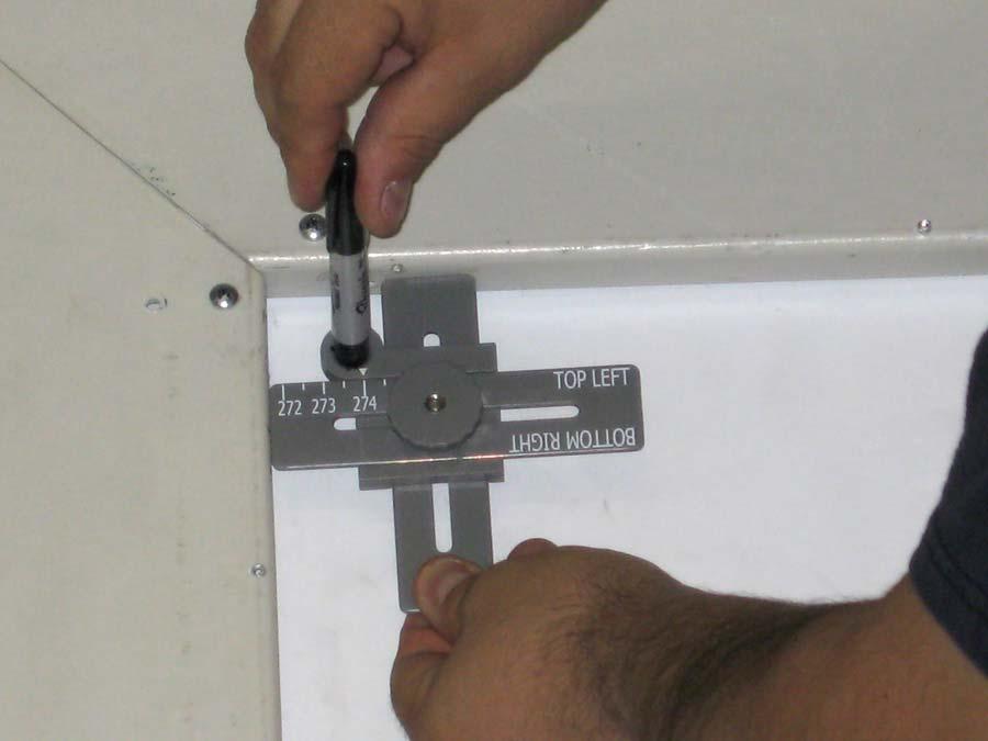
17 Align the arrow on the Corner Measurement Tool with the vertical measurement of the poster panel and lock in the setting. Now the Corner Measurement Tool is set and ready to assist you in determining the location of the corner guides for your system. Install the Corner Guides starting with the bottom left by placing the corner cable guide as set forth in the picture below. BOTTOM LEFT Orient the ruler so that the corner name is upright and readable. Mark the location as shown above using a Sharpie Fine Point marker (this style fits the hole in the tool perfectly). Now that you have marked the precise location of the corner of the guide, you are ready to secure the corner guide. If you are using rivets (i.e., you are installing into a metal panel), use the long rivet in the standoff hole on the corner guide and the short rivet for hole on the plate. If you are installing into a wooden panel, use screws for both holes. Page 9 of 14


18 Install the corner guide at the marked location as depicted below. Once installed, you need to install the other 3 corner cable guides. The following pictures show the Corner Measurement Tool orientation for the Bottom Right, Top Left, and Top Right. Mark the location and proceed w/ the corner guide installs as you did with the Lower Right corner. Page 10 of 14


19 BOTTOM RIGHT TOP LEFT Page 11 of 14

20 TOP RIGHT Now that you have located the proper position of the corner guides using the Corner Measurement Tool and you have actually installed all 4 corner guides you need to install the standard guides. In preparation to install the standard cable guides, temporarily install the cable guide template for the bottom. Attach the template to the corner guides so that the printed arrow points towards the billboard trim. See pictures below. Page 12 of 14
21 Install a standard cable guide in every hole. If you are installing into metal panels, use Long Rivets for the standard guides. If you are installing into wood panels, use wood screws. Note, the smaller diameter of the guide goes against the face of the panel. See picture below. After installing the cable guides per the bottom template, make use of the template again in order to install the wind strap hardware. Center the wire wind-strap bracket at each of the four black dots along the bottom. The bracket should be directly against the trim. See picture below. Remove and store the bottom template guide in your vest. The next step is to install the cable guides along the top, using the Top template guide. Remember to attach the template to the corner guides so that the printed arrow points towards the billboard trim. Also, on the top template guide, be careful that the template guide does not sag in the middle. Make sure to lift the top template up, removing for any slack left in the template. Following the installation of the top cable guides, use the side template guide to install three standard cable guides, each on the left and the right side. Note the same template (marked side ) is used for both left and right. IMPORTANT: When using the side template, the template must be attached to upper AND lower corner cable guides. Failure to do so will result in improper spacing. Store both templates back in the installation vest. Page 13 of 14
 of the billboard. Position the part at a reachable height from the cat-walk platform.")

22 You should now have installed a total of 17 standard cable guides as well as the 4 wire Wind-Strap brackets along the bottom. Step 6 Install Side Anchors Hardware for the Wind-Strap Install a wind-strap anchor on both sides (left and right) of the billboard. Position the part at a reachable height from the cat-walk platform. IMPORTANT: When installing the wind-strap anchors make sure that the side that receives the removable L-Bracket is as close to the trim as possible and the flat part of the plate is closer towards the center of the panel as seen below. Correctly installed on left side of panel Correctly installed on right side of panel The wind-strap brackets need to be installed so that they can be reached from the deck and so that they do not interfere with the poster clips. As with the installation of the cable guides, when installing the anchor guides on metal panels, use rivets (the short ones). If you are installing into wood panels, use wood screws. You should now have installed four corner guides, and 17 standard cable guides as well as the windstrap hardware. Congratulations, you have completed the most difficult aspect of the overall installation! The next step (at the appropriate time) would be to install the cable and clips and an actual Eco-Poster. Page 14 of 14
23 Cable & Clip Installation Guide Overview In order to be at this step, you will have already installed all Cable Guides and Wind-Strap hardware. Installation of the Cable (a very high strength liquid crystal polymer) and the Clips that hold and tension the poster is very straightforward and you will master this step easily after a few installations. Once the single sheet poster is established you will likely be switching out one Eco-Poster for another. However, during a transition from wet posting (i.e., glue posting) to dry posting, you may be required to post a paper poster in between dry postings. If this is the case, remove the cables and clips (not the cable guides) so that they are not damaged during the wet posting. Parts List Picture ID (below) Cables and Cinch Strap (1 per board) A Regular Clips (30 per board) B Wind-Straps C Snap-on Clip Extenders (10 per board) D Corner Clips - RIGHT (4 per board) E Corner Clips - LEFT (4 per board) F Page 1 of 15

24 Pictures of parts used in this step Step 1 Install the Cable To begin we need to install the cable within and around the four corner cable guides with the two ends of the cable ending up centered at the bottom as shown below. Note: The Cinch Strap (Gray box) is permanently affixed to the right hand side of the cable Page 2 of 15


25 Install the cable within the corner cable guides. To install the cable within the corner cable guides do the following: Install the cable under the gray lid. Pry the lid away from the black base to the cable under it It is not necessary to loosen the screw or remove the lid to install the cable. Once you ve installed the cable in all four corner guides, connect the LEFT END of the cable to the cinch strap and hand-tighten as shown below: Page 3 of 15


26 A couple of notes on the Cinch Strap 5/19/2008 The cable end-hooks are designed to fit securely around the cam of the cinch strap. They will loosen up after a couple of uses, making it easy to connect to the cinch strap. If the prongs on the left-hand side of the cable do not seem to fit into the cinch strap as shown, use a pair of pliers on the prongs to open them up slightly. When attaching the cable end hook to the cam, make sure handle loop at the end of the strap (which is doubled over and sewn) does not get wedged into the cam. The double layer in the cam makes it almost impossible to install the cable s hooks because the cam lever is in the way. Below there is the correct way and the incorrect way with the difference being that you should tighten the cinch strap slightly so that it is not at the very end. CORRECT INCORRECT Note with the Incorrect picture, the doubled over portion of the strap is wedged into the cam, making it impossible to attach the clip to the strap Page 4 of 15
27 Step 2 Install the Wind Strap (if not already installed) 5/19/2008 Install the wind-strap by first installing the L-Brackets into the side anchors on the left and right. Note the anchor bolts are a poster installation tool and should not be left on the poster panel permanently but rather taken along w/ the wind strap to each new poster removal/installation. Next, clip the ends of the horizontal and vertical straps into the side anchors and bottom brackets. Note this hardware should have been installed during the initial hardware installation (when the cable guides were installed). Page 5 of 15
28 The picture below demonstrates a fully installed wind-strap, attached in 6 places. 5/19/2008 Page 6 of 15

29 Step 3 Install the Clips on the Cable 5/19/2008 Our next step is to install the clips onto the cable. When you finish, the clips will be configured according to the illustration below (presume there is an invisible poster installed below). Page 7 of 15
: 5/19/2008 The")


30 Regular Clips (30x per board): 5/19/2008 The pictures below demonstrate how to slip the regular clip over the cable. Regular Clip w/ Extension (10x per board): Note the extenders are used on the top only Page 8 of 15
.")

31 The clip orientation for the regular clip is very important. Let s review how the regular clips will look using a bottom and a top view as set forth below. In the graphic above, the black area would be the panel face and the gray represents the trim (or bottom of the board in this case). The plastic triangle is pointed IN towards the inside of the panel and the metal wire tongue is completely visible and faces away from the panel face. If you always follow these two rules, you will always orient the regular clips in the correct way. Think of the metal wire tongue as pointing clockwise when the plastic tongue is pointing away from the trim (towards the center of the panel). In the graphic above, the black area still represents the panel face and the gray represents the trim (or top of the board in this case). The extended plastic triangle is pointed IN towards the inside of the panel and the metal wire tongue is completely visible and faces away from the panel face. Note the extenders that are snapped onto clips on the top. These extenders are helpful during poster installation in order to prevent the clips from flipping upside down. Page 9 of 15


32 Corner Clips (8 per board) Note the orientation of each of the 8 corner clips around the poster from the perspective of someone facing the poster. Clips are shown with the flat side (Bottom of the clip) facing out as they would be during a poster installation. The bumpy side of the clips (Top of the clip) will always go against the panel. Each corner will use one right and one left corner clip. Bottom Side Smooth This side faces the Eco-Poster Top Side Bumpy This side faces the panel Page 10 of 15

 that slides")


33 The Corner Clip is made of two separate pieces of high grade plastic which snap together around the cable. These two pieces are referred to as top and bottom. The bottom piece has a long plastic tongue (insert) that slides into the poster pocket. The top piece is the smaller of the two pieces. To take the pieces apart (in order to install the cable) press the tab on the top piece to disengage the top piece from the bottom piece. Next, position the cable between the two rows of hooks on the bottom piece and reconnect the two pieces. The corner clip should be installed on the cable so that the bottom piece (smooth side) faces you and the top piece (bumpy) is against the poster panel. The long plastic tongue (insert) should point towards the corner. It is very important to get the corner clips and regular clips installed in the correct orientation. Failure to do so will make proper Eco-Poster installation impossible Page 11 of 15


34 Left Side 2 corner clips and 6 regular clips for a total of 8 clips as shown. Right Side 2 corner clips and 6 regular clips for a total of 8 clips as shown. Page 12 of 15


35 Bottom Left Side 1 corner clip and 4 regular clips for a total of 5 clips as shown. Bottom Right Side : 1 corner clip and 4 regular clips for a total of 5 clips as shown. Page 13 of 15
.")


36 Now you need to install the 12 clips along the top of the cable (2 corner clips and 10 regular clips w/ clip extenders). In order to accomplish this you will need to lower the top cable by disconnecting the end of the cable from the Cinch Strap and attaching the ends of the cable to the Wind-Strap in order to create some slack. The ends of cable are attached to the Wind-Strap Next, pull the top cord down w/ the pole tool by lifting the cable off the top cable guides. Below is a picture of this step showing the ends of the cable attached to the wind strap to lower the cable. Also, the clips installed on the top cable (which is in the lowered position) are shown below: Page 14 of 15
. If you have a new poster, install it now per the Poster Installation Guide.")
37 Attach 12 clips to the top cable. Top Clips: 2 corner clips and 10 regular clips w/ clip extenders for a total of 12 clips as shown. This concludes the cable and clip installation guide. As far as next steps at this step, the options would seem to be: Install an Eco-Poster (the most logical next step). If you have a new poster, install it now per the Poster Installation Guide. If you are going to do a wet posting, remove the clip and cable prior to doing so. Also remove the wind-strap and anchor bolts. If you are going to leave the cable and clips but not install another poster at this time, reinstall the cable over the top cable guides (using the pole tool) and side guides and tighten the cinch strap and remove the Wind-Straps and L-Brackets. Page 15 of 15
38 Eco-Poster Installation Guide Overview In order to be at this step, you will have already installed the Cable Guides, Wind-Strap, Cable and Clips. Follow the installation instructions exactly as outlined. Installing the posters in a different manner will not allow you to fully tension the poster and will likely result in wrinkles in the poster or some other defect. After you have installed several posters following the instructions exactly and you are confident you can make the system work as intended, then feel free to experiment and adapt the procedure as you see fit. Please view these videos in conjunction with reviewing these installation notes. Poster Installation Kit 2 Wind-Strap L-Brackets These slide into the square anchors on the panel 1 Wind-Strap 1 Telescoping Pole with Cable Handler Attachment screwed onto the end of it 1 Hand Tensioning Tool 1 Eco-Poster Bag (to carry new poster) 10 Recycling Bags (to carry old posters to recycling bin) Page 1 of 23
 to lock the clip into the poster and provide support when the poster is tensioned.")

39 Preparation - Practice Installing Corner Clips and Regular Clips into an Eco-Poster Corner Clip Installation The top piece has a latching hook that engages with the plastic tongue (from now on called insert ) to lock the clip into the poster and provide support when the poster is tensioned. Before attempting to install a corner clip into the poster pocket, start by familiarizing yourself with the latching mechanism. Twist the insert to disengage the latch from the insert and twist again to reconnect the two pieces. Hold the insert firmly and pull it away from the latch. Pull and twist so the latch disengages from the insert. Do this several times before installing your first corner clip. Page 2 of 23


40 Once you are comfortable engaging and disengaging the latch, leave the latch in the disengaged position and insert into the pocket as follows: 1) Insert the tip of the insert into the poster pocket: 2) Pull the latch away from the pocket and slide the clip fully into the pocket: Page 3 of 23


41 3) Latch into the insert through the second pocket slit on the poster: As another example, please review the sequence below illustrating a corner clip installation of a the bottom, side corner clip into an eco-poster. Page 4 of 23

42 Final important installation note on Corner Clip Installation. Make certain that the Corner Clip latches back to itself AFTER YOU INSTALL it into the pocket. Relax This can be a little frustrating at first. Once you get a feel for it, you can do it with your eyes closed. Important: If the corner clips are NOT latched properly, the installation will fail. Page 5 of 23


43 R egular Clip Installation The pictures below show a regular clip being inserted into an Eco-Poster pocket.. Note location of pocket. When fully inserted, none of the wire tongue is visible Clip Fully Installed BE SURE TO INSERT THE CLIP FULLY INTO THE POCKET Page 6 of 23


44 Step 1 Install the Wind Strap (if not already installed) Install the wind-strap by first installing the L-Brackets into the side anchors on the left and right. Note the anchor bolts are a poster installation tool and should not be left on the poster panel permanently but rather taken along w/ the wind strap to each new poster removal/installation. Next, clip the ends of the horizontal and vertical straps into the side anchors and bottom brackets. Note this hardware should have been installed during the initial hardware installation (when the cable guides were installed). Page 7 of 23

45 The picture below demonstrates a fully installed wind-strap, attached in 6 places. Page 8 of 23

46 Step 2 5/19/2008 Lower the cable in Preparation for Poster Installation Your cable may be cinched on the bottom as shown below. Loosen the cinch completely and attach the ends of the cable to the wind strap as shown below. Be careful not to wedge the doubled over handle loops at either end of strap into the cam. The ends of cable are connected to the Wind-Strap. Here they are aligned with the inside vertical black Wind-Straps (Some slack in the cable, but not lowered enough for poster installation) Page 9 of 23
.")
 This is what the")
47 To allow for the maximum amount of slack, slide each end of the cable across the wind-strap so the end of the cable is aligned with the outside vertical black straps (See close ups below). This will lower the cable enough to allow you to install the clips in the poster. The ends of cable are aligned with the outside vertical black Wind-Straps (for Maximum slack) This is what the cable will look like when it is fully lowered Page 10 of 23

48 Step 3 Unroll the Eco-Poster behind the wind straps Unroll the Eco-poster starting on the bottom left corner (as you face the poster). Unroll the Eco-Poster from left to right and make sure you unfold it behind the wind straps as pictured below. Note: Your Eco-Poster will come from Circle Graphics folded correctly to facilitate this installation method. Just remember to start at the bottom left and unfold to the right. Page 11 of 23
49 Step 4 5/19/2008 Install Clips into TOP HALF of the Eco-Poster Install clips in the following order: 1. Corner Clip Top, Right, Side 2. Corner Clip Top, Right 3. Regular Clips Top, Right, Side (three clips on the upper right side of the poster, below the corner clip) 4. Regular Clips w/ Clip Extenders Along Top (see illustration on top of next page) 5. Corner Clip Top, Left, Side 6. Corner Clip Top, Left 7. Regular Clips Top, Left, Side (three clips on the upper left side of the poster, below the corner clip) Page 12 of 23

50 The picture below depicts an installer moving from right to left and inserting the 10 regular clips with clip extenders into the rear pocket of an Eco-Poster. Step 5 Raise the Cable w/ the Pole and Secure over Page 13 of 23

51 the Five (5) Cable Guides along the top Using the telescoping pole with cable handler screwed into the tip, secure the cable to all 5 top cable guides, beginning with the cable guide in the middle and working your way out both sides. There must be two clips between each cable guide along the top. The picture below illustrates the installer putting the cable over the top middle guide. Page 14 of 23

52 The series of pictures below illustrates the installer putting the cable over the remaining top cable guides along the top. Note how the poster is lifted to within approximately 2 feet of the top of the board at the conclusion of this step. Page 15 of 23

53 Page 16 of 23 5/19/2008
.")
54 Step 6 Raise the poster Raise the poster by connecting the ends of the cable together at the bottom. Do this by sliding the cable from each side along the Wind-Strap towards the center. The poster will rise as you do this. Connect the left end of the cable to the cinch strap (which is the other end of the cable, on the right). Make sure the cable is BEHIND THE WIND-STRAP at this point. DO NOT TENSION AT THIS TIME. JUST ATTACH THE LEFT END OF THE CABLE TO THE END OF THE CINCH STRAP. The picture above shows what the poster should look like after this step. Page 17 of 23
55 Step 7 5/19/2008 Install Clips into the BOTTOM HALF of the Eco-Poster Install clips in the following order: 8. Corner Clip Bottom, Right (See close up on next page) 9. Regular Clips Bottom, Right, Side (three clips on the bottom right side, above the corner clip) 10. Corner Clip Bottom, Right, Side 11. Regular Clips Bottom, Right (four clips along the bottom working from the bottom right to center) 12. Corner Clip Bottom, Left (See close up on next page) 13. Regular Clips Bottom, Left, Side (three clips on the bottom left side, above the corner clip) 14. Corner Clip Bottom, Left, Side 15. Regular Clips Bottom, Left (four clips along the bottom working from the bottom left to center) Page 18 of 23

 installed first, it will be impossible to flip")
56 #8 Bottom side of the bottom right corner 5/19/2008 #12 Bottom side of the bottom left corner Install these clips first so you can flip up the bottom of the poster and see what you are doing. If the corner clips on the sides (#10 and #14) installed first, it will be impossible to flip the poster up to monitor the installation of corner clips on the bottom (#8 and #12) Page 19 of 23


57 Step 8 5/19/2008 Install Cable around the Upper Cable Guide on Each Side Now that all clips are in the poster, install the cable over the upper cable guides on each side (left and right). These guides are depicted by the arrows in the illustration below. Use the pole to direct the cable around the guide, just below the top two clips. There are three side guides on each side, but you should only need to use the pole to reach the very top guide on either side. DO NOT INSTALL THE CABLE OVER THE LOWER SIDE GUIDES AT THIS TIME. Page 20 of 23

58 Step 9 Tighten the Cinch Strap 5/19/ CENTER & SLIDE: Grab the ends of the cinch strap (before tightening) as shown below and slide it back and forth. By sliding the cable back and forth, you will find that the entire poster will move easily over the guides. This step is important because it balances the tension around the perimeter and raises the poster. Take this opportunity to Center the poster so that an equal amount of space (if any) shows on the left and right sides. 2. Next, pull the cinch snug and make sure the poster doesn t get stuck under the Corner Cable Guide hardware. Use pole as needed if poster gets stuck under a corner. When you have confirmed that the corners of the poster will clear the corner hardware, pull the cinch tight. Pull equally in both directions for balanced tension. Here the poster is caught on the Corner Cable Guide hardware Before you fully tension the cinch, use the pole to position the poster above the Corner Cable Guide hardware Now the poster is above the hardware, so when you fully tighten the cinch, the poster will cover it Page 21 of 23

59 Step 10 Final Tensioning - Secure the cable over the remaining cable guides along the bottom and the sides. 1. Use the hand tensioning tool (depicted to the right) as needed along the lower left side (two guides), along the bottom, and on the lower right side (two guides). IMPORTANT NOTE: FOR THE VERY BEST POSTER INSTALLATION ALWAYS INSTALL THE CABLE OVER THE CABLE GUIDES ON THE BOTTOM HALF OF THE POSTER AFTER HAND TIGHTENING THE CINCH 2. Place the cable over the two cable guides on either side of the cinch and tuck the entire cinch strap assembly behind the poster. 3. Finally, remove the wind-strap by unclipping from the anchor bolts. Also remember to remove the Wind-Strap L-Brackets for use on the next panel Page 22 of 23

60 Here s the Finished Product! Congratulations!! Page 23 of 23


61 Poster Removal Guide Install the wind strap. Install the anchor bolts. Then install the wind-strap to the anchor bolts on the left and right. Then install the 4 vertical straps to the bottom anchors. Loosen the cinch strap. Page 1 of 2

62 Using the pole tool, take the cable off the top, middle guide and then the rest of the guides along the top and the two upper guides on the top left and top right. Remove the clips and take the cable off the rest of the cable guides from the bottom half of the Eco- Poster (all clips within reach on the left side, all along the bottom, and all clips within reach on the right side) Lower the poster to remove the remaining clips. Do this by disconnecting one end of the cable from the cinch strap and snap it to the wind-strap. Then slide the cable along the wind-strap to lower the poster. Repeat this on the other end of the cable to drop the poster to a workable height. Remove all remaining clips (i.e., all clips on the top half of the poster) The poster will fall down and be caught w/ the wind straps. Now take and stuff the loose poster into a take-up bag. As you move along the catwalk and stuff the poster, you will need to unclip the 4 vertical wind straps and reconnect them after moving past. Now the poster is removed. Now that the old poster has been removed, you will likely do one of the following: If you have a new poster, install it now per the Poster Installation Guide. If you are going to do a wet posting, remove the clips and cable prior to doing so in order to preserve these parts and protect from the glue. Remove the wind-strap and anchor bolts. If you are going to leave the cable and clips but not install another poster at this time, reinstall the cable over the top cable guides (using the pole) and side guides and tighten the cinch strap. Remove the wind-strap and anchor bolts. Page 2 of 2
Coyote popup display set up instructions
 Coyote popup display set up instructions Frame 1 2 3 Prepare frame for assembly by locating the purple hooks on top of the frame. Stretch frame to size, snapping magnetic locking arms together. Attach
FOSC-600 C and D I N S T A L L A T I O N I N S T R U C T I O N
 FOSC-600 C and D I N S T A L L A T I O N I N S T R U C T I O N In-line and butt version Cold applied re-usable fiber optic closure Contents 1 Introduction 1.1 Product description 1.2 Capacity 2 General
NewScope-7A Operating Manual
 2016 SIMMCONN Labs, LLC All rights reserved NewScope-7A Operating Manual Preliminary May 13, 2017 NewScope-7A Operating Manual 1 Introduction... 3 1.1 Kit compatibility... 3 2 Initial Inspection... 3 3
Installation Guide OvalSox TM Cable
 Installation Guide OvalSox TM Cable Thank you for selecting a DuctSox System. This guide will be helpful for the installation of an OvalSox Cable System. Sections of fabric will be labeled, assembled,
GENUINE PARTS ! CAUTION
 GENUINE PARTS SATELLITE RADIO INSTALLATION INSTRUCTIONS 1. DESCRIPTION: SATELLITE RADIO SYSTEM 2. PART NUMBERS: XM tuner kit 999U9-NV003 Sirius tuner kit 999U9-NV004 XM antenna kit 999U9-VQ006 Sirius antenna
Motor Operated Solar Shade with Valance Installation and Care Instructions Complete Video Instructions Available Online at
 * Motor Operated Solar Shade with Valance Installation and Care Instructions Complete Video Instructions Available Online at www.keystonefabrics.com Step 1: Identify the parts of your shade (parts shown
READ ME FIRST. Touchstone TV Lift
 Whisper Lift II PRO 2 READ ME FIRST 1. After completing the unpacking and uncrating of the cabinet, you will find the Owner s Manual, TV, installation hardware, and the wireless remote all together and
Coyote popup features
 Coyote popup features The Coyote popup display system combines strength, reliablility, and style in a lightweight and easy to use system. It is fully magnetic, making it simple to assemble and disassemble,
3M Distribution Box (DDB)
") 3M Distribution Box (DDB) Merged Copper and Fiber Pole/Post Mount Enclosure Installation Instructions November 2015 78-0015-2736-1-A 2 November 2015 78-0015-2736-1-A Contents 1.0 General 2.0 Enclosure
3M Distribution Box (DDB) Merged Copper and Fiber Pole/Post Mount Enclosure Installation Instructions November 2015 78-0015-2736-1-A 2 November 2015 78-0015-2736-1-A Contents 1.0 General 2.0 Enclosure
Assembling and Mounting the Presentation Display, Speakers, Speaker Screens, and Table Door
 CHAPTER 8 Assembling and Mounting the Presentation Display, Speakers, Speaker Screens, and Table Door July 13, 2012, This document provides you with the procedures you perform to assemble and mount the
Order #XXXXX - ECO x10 Inline Display. Setups. 10 Plan View
 Order #XXXXX - ECO-054-0 x0 Inline Display Setups 0 0 Plan View 7A General Setup Instructions The setup instructions are created specifically for your configuration. Setup instructions are laid out sequentially
Check what you have received against the component checklist and hardware above.
 SA46S SA46W SA46B SA46PB Component Checklist Installation Instructions SYSTEMA Systema Monitor Arm 460mm HARDWARE Display Mounting Spacers (x4) Display Mounting Screws Arm Assembly VESA monitor head M4
MIRAGE. Skyline Mirage Set-Up Instructions Skyline Exhibits
 MIRAGE Skyline Mirage Set-Up Instructions www.skyline.com Table of Contents Mirage Pop-up is available in many sizes from 32 tall tabletops to 92 tall backwalls. The following set-up and repacking instructions
Satellite Dish Installation Manual (Ver. 2) 1
 1") Satellite Dish Installation Manual Provided by DiscoverNet, Inc. Satellite Dish Installation Manual (Ver. 2) 1 Table of Contents Section 1: Introduction Page 3 Section 2: Recommended Tools and Materials
Satellite Dish Installation Manual Provided by DiscoverNet, Inc. Satellite Dish Installation Manual (Ver. 2) 1 Table of Contents Section 1: Introduction Page 3 Section 2: Recommended Tools and Materials
iphone 7 Plus LCD Screen and Digitizer Replacement
 iphone 7 Plus LCD Screen and Digitizer Replacement Replace just the bare front panel not including the home/touch ID sensor, front-facing camera and sensor cable, or earpiece speaker in an iphone 7 Plus.
TV Lift System Model CL-65 Installation Instructions
 TV Lift System Model CL-65 Installation Instructions Contact: Support@Nexus21.com Toll Free: (866) 500-5438 Phone: (480) 951-6885 Fax: (480) 951-6879 Revised: 01/17/17 Below is a parts list describing
Force & Motion 4-5: ArithMachines
 Force & Motion 4-5: ArithMachines Physical Science Comes Alive: Exploring Things that Go G. Benenson & J. Neujahr City Technology CCNY 212 650 8389 Overview Introduction In ArithMachines students develop
velocity standard 07 velocity features and benefits: dimensions: additional information:
 velocity standard 07 V-S-07 Chic and robust - a highly-structural portable 10 x10 exhibit that emphasizes your identity and message seamlessly with a combinaton of fabric graphics, rigid accents and accessories.
HQ Electromagnetic Channel Locks
 HQ Electromagnetic Channel Locks Table of Contents Overview... 2 Kit Contents... 2 Tools Required... 5 Installation... 5 Using the HQ Electromagnetic Channel Locks... 10 Troubleshooting... 11 Overview
K Service Source. Apple High-Res Monochrome Monitor
 K Service Source Apple High-Res Monochrome Monitor K Service Source Specifications Apple High-Resolution Monochrome Monitor Specifications Characteristics - 1 Characteristics Picture Tube 12-in. diagonal
velocity standard 08 velocity features and benefits: dimensions:
 velocity standard 08 V-S-08 Chic and robust - a highly-structural portable 10 x20 exhibit that emphasizes your identity and message seamlessly with a combinaton of fabric graphics, rigid accents and accessories.
GENUINE PARTS CAUTION
 GENUINE PARTS SATELLITE RADIO INSTALLATION INSTRUCTIONS 1. DESCRIPTION: SATELLITE RADIO SYSTEM 2. PART NUMBERS: XM tuner kit 999U9-NV003 XM antenna kit 999U9-VR000 Sirius tuner kit 999U9-NV004 Sirius antenna
FOSC 450 C6 and D6 Closures
 FOSC 450 C6 and D6 Closures I N S T A L L A T I O N I N S T R U C T I O N Fiber Optic Splice Closure 1. General Product Information The FOSC 450 C6 and D6 fiber optic splice closures use compressed gel
IP-LINX Fiber :: X-XXXX
 Fiber :: 055-797X-XXXX User Manual Telect, Inc. All rights reserved. 146653-A0 Table of Contents Chapter 1: Introduction...3 1.1 Tools Required...3 1.2 Additional Parts...3 1.3 Assemblies...3 Chapter 2:
3. Electronics and MMU2 unit assembly
 Written By: Jakub Dolezal 2018 manual.prusa3d.com/ Page 1 of 34 Step 1 Tools necessary for this chapter Please prepare tools for this chapter: 2.5mm Allen key for M3 screws 2mm Allen key for nut alignment
SLiC Fiber Aerial Closure System
 3 SLiC Fiber Aerial Closure System SLFC 533-SP SLFC 533-TS SLFC 733-SP Instructions May 2005 78-8135-4502-3-B N C H E S R A N G E M IL L IM E T E R S.4 10.6.8 A B C 15 20 I 1.0 Kit Contents Note: Examine
PowerBook G4 Aluminum 12" GHz LCD panel upgrade
 PowerBook G4 Aluminum 12" 1-1.5 GHz LCD panel upgrade Upgrade a 1400x1050 LCD panel. Written By: martin ifixit CC BY-NC-SA www.ifixit.com Page 1 of 18 INTRODUCTION The original LCD 1024x768 resolution
K Service Source. Apple High-Res Monochrome Monitor
 K Service Source Apple High-Res Monochrome Monitor K Service Source Specifications Apple High-Resolution Monochrome Monitor Specifications Characteristics - 1 Characteristics Picture Tube 12-in. diagonal
imac Intel 20" EMC 2133 and 2210 LCD Backlights (CCFL) Replacement
 Replacement") imac Intel 20" EMC 2133 and 2210 LCD Backlights (CCFL) Replacement The CCFL back lights are replaceable. I have pulled mine apart and documented my method. '''NOTE''' This is not for the feint hearted!
imac Intel 20" EMC 2133 and 2210 LCD Backlights (CCFL) Replacement The CCFL back lights are replaceable. I have pulled mine apart and documented my method. '''NOTE''' This is not for the feint hearted!
Modulate Magnetic Kit 10-01
 Modulate Magnetic Kit 10-01 MOD-10-01-M MOD-10-01-M-OCE Modulate Fabric Banner kits feature unique angles and shapes, are portable and now are even easier to configure to achieve your dream space! Modulate
ipad Air 2 Wi-Fi Display Assembly Replacement
 ipad Air 2 Wi-Fi Display Assembly Replacement Fix a cracked or faulty screen by replacing the display assembly in an ipad Air 2 Wi-Fi. Geschreven door: Evan Noronha ifixit CC BY-NC-SA nl.ifixit.com Pagina
Creative Suggestions & Billboard Installation
 TMNT CAMPAIGN LOS ANGELES, CA These instructions include creative suggestions as well as handling, installation, and dismantling step by step guides for Light Tape Billboard Installations. R R Creative
AUDIO ROOF KIT P/N , , APPLICATION BEFORE YOU BEGIN KIT CONTENTS. Instr Rev Page 1 of 6
 AUDIO ROOF KIT P/N 2882064, 2882065, 2882066 APPLICATION Verify accessory fitment at Polaris.com. BEFORE YOU BEGIN Read these instructions and check to be sure all parts and tools are accounted for. Please
Mitsubishi WD57734 DLP Chip Replacement
 Mitsubishi WD57734 DLP Chip Replacement Replace the DLP chip in your Mitsubishi WD57734. Written By: David Sylvester ifixit CC BY-NC-SA www.ifixit.com Page 1 of 10 INTRODUCTION This guide will detail the
IP-LINX. Installation Guide
 Installation Guide Installation Guide, 146653-4 Copyright 2017, Telect, Inc. All Rights Reserved Telect and Connecting the Future are registered trademarks of Telect, Inc. 22425 East Appleway Ave. # 11
INSTALLATION INSTRUCTIONS
 INSTALLATION INSTRUCTIONS PARTS REQUIRED Parts in the box Single monitor Dual monitor M2 M8 M/Flex + (package contents will depend on configuration ordered) Tools required for installation 6.0 mm Hex Key
1.0 DESCRIPTION. This specification covers roll-up signs to be used in temporary traffic control zones.
 (Page 1 of 10) ROLL-UP SIGNS (MGS-04-01O) 1.0 DESCRIPTION. This specification covers roll-up signs to be used in temporary traffic control zones. 2.0 MATERIAL. 2.1 SIGNS AND OVERLAYS. 2.1.1 SUBSTRATES.
24-Fiber LANLINXS (Model # ) 48-Fiber LANLINXS (Model # ) User Manual
 48-Fiber LANLINXS (Model # ) User Manual") 24-Fiber LANLINXS (Model # 055-8632-5000) 48-Fiber LANLINXS (Model # 055-8832-5000) User Manual 24-Fiber LANLINXS (Model # 055-8632-5000) 48-Fiber LANLINXS (Model # 055-8832-5000) User Manual, Part Number
24-Fiber LANLINXS (Model # 055-8632-5000) 48-Fiber LANLINXS (Model # 055-8832-5000) User Manual 24-Fiber LANLINXS (Model # 055-8632-5000) 48-Fiber LANLINXS (Model # 055-8832-5000) User Manual, Part Number
Nava Buffet Assembly Instructions
 Thank you for your purchase. lease follow the instructions below for correct assembly. B dowel x0 x1 bolt x H height adjuster x1 bracket x Q clip x R locking nut x K seal x S F x shelf plugx8 x8 L hinge
Check what you have received against the component checklist and hardware above.
 SSS SSPW SSW SSPB SSB Component Checklist Installation Instructions SYSTEMA Systema Monitor Spring Arm HARDWARE Display Mounting Spacers (x4) 3/4mm Allen Keys Display Mounting Screws M4 x 14mm (x1) Silver
3 Closure preparation 3.1 Work-stand 3.2. Opening FIST-GCOG2-Dx Preparing drop cable with micro-tubes
 FIST-GCOG2-Dx24 I N S T A L L A T I O N I N S T R U C T I O N FTTH closure for micro-tubes and micro-cables Content 1 Introduction 2 Kit content 3 Closure preparation 3.1 Work-stand 3.2. Opening FIST-GCOG2-Dx24
MY-HITE ADJUSTABLE TABLE
 MY-HITE ADJUSTABLE TABLE Corner T Leg Base Model Number : FCNAHBT Please Read Instructions Before Use ASSEMBLY INSTRUCTIONS ALL WORKSTYLES WELCOME Thank you for choosing Friant. We appreciate the trust
Installing a Wire Mesh Pulling Grip on All-Dielectric DX Armored Fiber Optic Cables
 revision history Issue Date Reason for Change Related literature SRP-004-136 Accessing All-Dielectric DX Armored Fiber Optic Cables Admonishments 1. General This procedure provides instructions for installing
HCS - HES Cabling Systems
 HCS - HES Cabling Systems Installation Manual for HCS High-Capacity Fiber-Optic Rack-Mount Cabinets Be sure to read and completely understand this procedure before applying product. Be sure to select the
1.2 GHz GS7000 Node RF Split Upgrade Application Note
 1.2 GHz GS7000 Node RF Split Upgrade Application Note Overview Introduction Cable operators have experienced an exponential rise in the requirement for more reverse path bandwidth due to the popularity
Physical Processing Guidelines for Shelf- Ready Chinese Approval Materials
 Physical Processing Guidelines for Shelf- Ready Chinese Approval Materials Last Revised 11/20/2012 NOTE: The following guidelines illustrate how materials should be processed physically. These guidelines
3 Foam Sealed Closure 2" (50 mm) with Compound Compression
 with Compound Compression") 3 Foam Sealed Closure 2" (50 mm) with Compound Compression Instructions 1.0 General 1.1 The 3M Foam Sealed Closure is designed to be used in the construction and maintenance of buried and underground PIC
3 Foam Sealed Closure 2" (50 mm) with Compound Compression Instructions 1.0 General 1.1 The 3M Foam Sealed Closure is designed to be used in the construction and maintenance of buried and underground PIC
INSTALLATION INSTRUCTIONS FOR
 INSTALLATION INSTRUCTIONS FOR MODEL 2240LED www.sportablescoreboards.com 1 Table of Contents 8 X 7 INDOOR SCOREBOARD... 3 THE SCOREBOARD SYSTEM SHOULD INCLUDE THE FOLLOWING PARTS:... 3 INSTRUCTIONS FOR
apple Service Source Apple Studio Display 17" LCD (ADC) Updated 6 Decenber Apple Computer, Inc. All rights reserved.
 Updated 6 Decenber Apple Computer, Inc. All rights reserved.") apple Service Source Apple Studio Display 17" LCD (ADC) Updated 6 Decenber 2004 2003 Apple Computer, Inc. All rights reserved. apple Service Source Take Apart Apple Studio Display 17" LCD (ADC) 2003 Apple
apple Service Source Apple Studio Display 17" LCD (ADC) Updated 6 Decenber 2004 2003 Apple Computer, Inc. All rights reserved. apple Service Source Take Apart Apple Studio Display 17" LCD (ADC) 2003 Apple
TO THE INSTALLER: BE SURE TO LEAVE THIS MANUAL WITH THE OWNER.
 Fixed Frame Screen Owner s Manual To the Owner Installation Instructions Screen Care CFS-010517 Maintenance TO THE INSTALLER: BE SURE TO LEAVE THIS MANUAL WITH THE OWNER. Printed in U.S.A. Stewart Filmscreen
Nava Entertainment Unit Assembly Instructions
 ava ntertainment nit ssembly nstructions Thank you for your purchase. Please follow the instructions below for correct assembly. B dowel x2 x8 H locking nut x22 Q x32 x10 x10 K bracket x P bolt x22 height
High Performance DL-60 (Gold Plus) (7 in - 13 in) Dual Lane Spliceable Tape Feeder Part Number: Revision 3 Sep No.
 (7 in - 13 in) Dual Lane Spliceable Tape Feeder Part Number: Revision 3 Sep No.") 8mm High Performance DL-60 (Gold Plus) (7 in - 13 in) Dual Lane Spliceable Tape Feeder Part Number: 50381212 Revision 3 Sep. 2010 No. 0730D-E043 Page i Table of Contents Functional Description...1 Procedures
8mm High Performance DL-60 (Gold Plus) (7 in - 13 in) Dual Lane Spliceable Tape Feeder Part Number: 50381212 Revision 3 Sep. 2010 No. 0730D-E043 Page i Table of Contents Functional Description...1 Procedures
FIST-GCOG2-Dx6. Follow all local safety regulations related to optical fiber plant elements.
 FIST-GCOG2 I N S T A L L A T I O N I N S T R U C T I O N TC-986-IP Rev A, Mar 2017 www.commscope.com FIST-GCOG2-Dx6 Content 1 Introduction 2 General 2.1 Abbreviations 2.2 Kit contents 2.3 Tools 2.4 Accessories
Troubleshooting Guide for E-Poll Book
 Troubleshooting Guide for E-Poll Book CHANGING USERS ON THE E-POLL BOOK Changing Users on the E-poll Book 1. Tap Return to Main button on the voter search screen. 2. Tap on the Manage Polls tab in the
In-Wall Control Mount for ipod Touch
 In-Wall Control Mount for ipod Touch INTRODUCTION The Mirage KP-iOS is an in-wall system that allows ipod touch (4th generation) to become a semi-permanent fixture in your wall. The system allows you to
Modulate Magnetic Kit 10-07
 Modulate Magnetic Kit 10-07 MOD-10-07-M MOD-10-07-M-OCE Modulate Fabric Banner kits feature unique angles and shapes, are portable and now are even easier to configure to achieve your dream space! Modulate
Snail Fence InteleCell Deployment Guide
 Snail Fence InteleCell Deployment Guide Preparation 1. Prepare deployment trip by making sure you have the following materials and tools when you fly up to the site: InteleCell NEMA Enclsoure (grey plastic
Technical Information Bulletin
 June 4, 2001 #TIB0003 Units Affected: Model Serial Numbers Model Serial Numbers SVT-2PRO T2PDxxxxxxxxx SVTAV AXVDxxxxxxxxx ATLDxxxxxxxxx BJIDMAxxxxxxx SVT-2PROJ T2PJxxxxxxxxx SVTAVJ BAHJxxxxxxxxx ATLJxxxxxxxxx
Instrument Care. Band. Instruction Pack. Print and hand out! Instruments:
 Band Instrument Care Instruction Pack Print and hand out! Instruments: Flute Oboe Bassoon Clarinet Saxophone Trumpet French Horn Trombone Euphonium Tuba Percussion Easy-to-read Pictures included!! Before
CONNECTING THE FUTURE 19" LINXS LIGHTWAVE INTEGRATED CROSS-CONNECT SYSTEM USER MANUAL
 CONNECTING THE FUTURE 19" LINXS LIGHTWVE INTEGRTED CROSS-CONNECT SYSTEM USER MNUL 109003 Issue Rev 2 19" Lightwave Integrated Cross-Connect System (LINXS) User Manual Document Number 109003 Issue Rev 2
HD Flex Patch Panel. ASSEMBLY VIEW (FLEX1UPN** shown) FS128B. CONTENTS: (#) indicates FLEX4UPN** quantity
 FS128B. CONTENTS: (#) indicates FLEX4UPN** quantity") HD Flex Patch Panel Part Numbers: FLEX1UPN**, FLEX2UPN**, FLEX4UPN** Panduit Corp. 2018 INSTALLATION INSTRUCTIONS Note: HD Flex Patch Panels are compatible with HD Flex Fiber System Components. HD Flex
HD Flex Patch Panel Part Numbers: FLEX1UPN**, FLEX2UPN**, FLEX4UPN** Panduit Corp. 2018 INSTALLATION INSTRUCTIONS Note: HD Flex Patch Panels are compatible with HD Flex Fiber System Components. HD Flex
Obtained from Omarshauntedtrail.com
 http://www.cindybob.com/halloween/ledlighting/ledspotlights/ Introduction In our 2005 haunt providing 120V AC power to the various lights and props requiring it became a fairly large problem. Extension
Table 4-1: Rating Levels
 OBJECTIVES 1. Describe various level ratings that apply to telecommunication cables and jacks and identify where each is implemented. 2. Describe the various levels of the cabling category rating systems.
Samsung Galaxy J3 (2016) Screen
 Screen") Samsung Galaxy J3 (2016) Screen Replacement This guide shows how to replace the screen on your Samsung Galaxy J3 (2016). This includes the front glass, digitizer, and LCD panel. Written By: Arthur Shi
Samsung Galaxy J3 (2016) Screen Replacement This guide shows how to replace the screen on your Samsung Galaxy J3 (2016). This includes the front glass, digitizer, and LCD panel. Written By: Arthur Shi
Lynx Broadband Installation Manual for Residential Packages with a 35 db Amp Quick Start Guide (first 3 pages)
") Lynx Broadband Installation Manual for Residential Packages with a 35 db Amp Quick Start Guide (first 3 pages) 1. Be sure that your kit includes all the parts shown in the Check the Equipment section in
Lynx Broadband Installation Manual for Residential Packages with a 35 db Amp Quick Start Guide (first 3 pages) 1. Be sure that your kit includes all the parts shown in the Check the Equipment section in
2.1 Kit Contents 2.2 Elements needed from the FIST installation kit 2.3 Tools 2.4 Cable preparation table
 FIST-GCO2-F INSTALLATION INSTRUCTION GCO2-FC GCO2-FD Content 1 Introduction 2 General 2.1 Kit Contents 2.2 Elements needed from the FIST installation kit 2.3 Tools 2.4 Cable preparation table 3 Installation
3M Better Buried Compound Compression Closure System
 3M Better Buried Compound Compression Closure System Instructions March 2016 78-0015-2948-2-A Contents: 1.0 General...3 2.0 Kit Contents...3 3.0 Closure Selection Guide...4 4.0 LHS End Cap Installation...5
USER S MANUAL. Save this manual for future reference. For a digital version of this manual, visit
 TM USER S MANUAL Save this manual for future reference. For a digital version of this manual, visit www.mylifter.com/installation. 4 5 TABLE OF CONTENTS 4 INSTALLING THE PULLEY SYSTEM FOR LIFTING 100
AT-AUTO (tm) QRO Keyline Upgrade Kit Installation Manual
 QRO Keyline Upgrade Kit Installation Manual") AT-AUTO (tm) QRO Keyline Upgrade Kit Installation Manual P.O. Box 341543 Beavercreek, Ohio 45434 5 September, 2015 Copyright 2015 ii Contents 1 Introduction 2 1.1 General Description and Purpose........................
AT-AUTO (tm) QRO Keyline Upgrade Kit Installation Manual P.O. Box 341543 Beavercreek, Ohio 45434 5 September, 2015 Copyright 2015 ii Contents 1 Introduction 2 1.1 General Description and Purpose........................
OFDC-B8-72. Outdoor fiber distribution closure. 6 Closing. Content 1 Introduction. 7 Re-entry. 2 Kit content. 3 Closure preparation
 OFDC-B8-72 I N S T A L L A T I O N I N S T R U C T I O N Outdoor fiber distribution closure Content 1 Introduction 2 Kit content 3 Closure preparation 4 Cable preparation 4.1 Feeder cable 4.2 Drop cable
DREAMOC DIAMOND 4K - ASSEMBLY GUIDE VERSION ORIGINAL ASSEMBLY GUIDE
 DREAMOC DIAMOND 4K - ASSEMBLY GUIDE VERSION 1.2 - ORIGINAL ASSEMBLY GUIDE It is important to read this assembly guide before using the Dreamoc Diamond, and to follow advices and instructions on safety,
Samsung HL56A650C1FXZA 56-inch DLP TV DLP Chip Replacement
 Samsung HL56A650C1FXZA 56-inch DLP TV DLP Chip Replacement A common failure item for Samsung DLP televisions is the DLP chip. Mirrors within the chip stick in one position or another, leading to white
LWX-1. Satellite Weather Radio Module Installation Instructions A
 LWX-1 Satellite Weather Radio Module Installation Instructions 988-0158-13A Copyright 2009 Navico All rights reserved. No part of this manual may be copied, reproduced, republished, transmitted or distributed
Setup Guide. Read me BefoRe unpacking!
 Setup Guide Read me BefoRe unpacking! Package Contents In The Replicator package The Replicator SD card (in The Replicator SD card slot) In the Accessory Box found within The Replicator frame Single or
High Performance (Gold Plus) Spliceable Tape Feeder Part Number: Part Number: Revision 3 Jun 2008 No.
 Spliceable Tape Feeder Part Number: Part Number: Revision 3 Jun 2008 No.") 8mm High Performance (Gold Plus) Spliceable Tape Feeder Part Number: 50934707 12mm High Performance (Gold Plus) Spliceable Tape Feeder Part Number: 50934807 Revision 3 Jun 2008 No. 0930D-E010 i Table
8mm High Performance (Gold Plus) Spliceable Tape Feeder Part Number: 50934707 12mm High Performance (Gold Plus) Spliceable Tape Feeder Part Number: 50934807 Revision 3 Jun 2008 No. 0930D-E010 i Table
GENUINE PARTS. SIRIUS Under Glass Antenna Kit
 GENUINE PARTS SATELLITE RADIO INSTALLATION INSTRUCTIONS 1. DESCRIPTION: Satellite Radio System 2. APPLICATION: Pathfinder (2006-2007) 3. PART NUMBERS: XM Tuner Kit 999U9-AS005 SIRIUS Tuner Kit 999U9-AS006
Gigabit Multi-mode SX to Single Mode LX Converter. User s Manual NGF-728 Series. Warning COPYRIGHT
 COPYRIGHT Gigabit Multi-mode SX to Single Mode LX Converter User s Manual NGF-728 Series All rights reserved. No part of this publication may be reproduced, stored in a retrieval system, or transmitted
MP Maker Pro Mk.1. Quick Start Guide
 MP Maker Pro Mk.1 P/N 33013 Quick Start Guide ONLINE SUPPORT Monoprice is pleased to provide free online support. For order related issues, contact the Customer Service department through the Live Chat
OWNER'S MANUAL SIGNAL COMMANDER
 OWNER'S MANUAL SIGNAL COMMANDER THIS MANUAL CONTAINS INSTRUCTIONS FOR: LPDA 200 - INSTALLATION - OPERATION - TROUBLESHOOTING - EXPLODED PARTS DRAWING - WARRANTY AntennaTek, Inc. 425 S. Bowen, #4 Longmont,
IPad 4 REPAIR GUIDE. Version Edition
 IPad 4 REPAIR GUIDE Version 1 2016 Edition IPad 4 REPAIR GUIDE LCD AND DIGITIZER REPLACEMENT RiAna Soto Repair Training Specialist rsoto@cellairis.com FOR EVERY REPAIR MAKE SURE TO COMPLETE, INITIAL, AND
3M Fiber Optic Wall Mount Enclosure 8430 Series
 3M Fiber Optic Wall Mount Enclosure 8430 Series Installation Instructions January 2014 3 78-0013-9429-1-A Table of Contents 1.0 Description...3 2.0 Parts...4 3.0 Assembly...4 4.0 Mounting the Enclosure...6
Scan-Light Supplement. Fitting instructions and hardware details For Mitsubishi MH105AG and MH216CG scanners
 Scan-Light Supplement Fitting instructions and hardware details For Mitsubishi MH105AG and MH216CG scanners Contents Contents Fitting instructions and hardware details... 1 For Mitsubishi MH105AG and MH216CG
D1.6 Audio Cassette Special Processing Guide
 D1.6 Audio Cassette Special Processing Guide Summary Most audio cassettes are playable in their current condition. This guide contains procedures for fixing cassette tapes which are not playable due to
IPad 3 (glass) REPAIR GUIDE. Version Edition
 REPAIR GUIDE. Version Edition") IPad 3 (glass) REPAIR GUIDE Version 1 2016 Edition IPad 4 REPAIR GUIDE LCD AND DIGITIZER REPLACEMENT RiAna Soto Repair Training Specialist rsoto@cellairis.com FOR EVERY REPAIR MAKE SURE TO COMPLETE, INITIAL,
IPad 3 (glass) REPAIR GUIDE Version 1 2016 Edition IPad 4 REPAIR GUIDE LCD AND DIGITIZER REPLACEMENT RiAna Soto Repair Training Specialist rsoto@cellairis.com FOR EVERY REPAIR MAKE SURE TO COMPLETE, INITIAL,
OWNER'S MANUAL SIGNAL COMMANDER
 OWNER'S MANUAL SIGNAL COMMANDER THIS MANUAL CONTAINS INSTRUCTIONS FOR: LPDA 100 - INSTALLATION - OPERATION - TROUBLESHOOTING - EXPLODED PARTS DIAGRAM - WARRANTY AntennaTek, Inc. 425 S. Bowen, # 4 Longmont,
Installation instructions, accessories. Subwoofer. Volvo Car Corporation Gothenburg, Sweden. Page 1 / 29
 Installation instructions, accessories Instruction No 30752136 Version 1.1 Part. No. 30752135 Subwoofer Volvo Car Corporation Subwoofer- 30752136 - V1.1 Page 1 / 29 Equipment A0000162 A0000161 A0801178
Linkage 3.6. User s Guide
 Linkage 3.6 User s Guide David Rector Friday, December 01, 2017 Table of Contents Table of Contents... 2 Release Notes (Recently New and Changed Stuff)... 3 Installation... 3 Running the Linkage Program...
Medium Box for Cable Termination
 FIST-MB2-T I N S T A L L A T I O N I N S T R U C T I O N Medium Box for Cable Termination Contents 1 Introduction 1.1 Product description. 2 General 2.1 Tools 2.2 Kit contents 3 Installation and pre assembling
Reference Manual. Notes 9/16 Series H
 Reference Manual Notes 9/16 Series 173.01H Copyright notice The information in this document is subject to change without prior notice and does not represent a commitment on the part of Q-MATIC AB. All
2.4 METER SERIES 1250 ANTENNA SYSTEM
 June 1,2009 Revision B Assembly Manual 2.4 METER SERIES 1250 ANTENNA SYSTEM General Dynamics SATCOM Technologies 1500 Prodelin Drive Newton NC 28658 2.4 Meter 2 Piece Az/El Installation Instructions B
Instructions. Cable with Armor F CAUTION. October Rev A
 3M Single Conductor Accessory Breakout Kits (BOK's) for use with 3M Cable Accessories (Terminations, T-Bodies and Push-On Elbows) For Use With Single Conductor Accessories On Three-Core Conductor Cables
Assembly instructions
 Assembly instructions Model: MXR0024/KIT TV Aerial - 18 Element Kit Contact: Helpline: +44 (0)1553 811000 Email: support@maxview.co.uk Web: www.maxview.co.uk Maxview reserve the right to change specifications
Embrace 2.5 Backlit Push-Fit Tension Fabric Display
 Embrace 2.5 Backlit Push-Fit Tension Fabric Display EMB-2-BL-1X1-S The Embrace 2.5ft tabletop (1 Quad x 1 Quad) backlit push-fit fabric display is a sleek illuminated collapsible display. The Backlit Embrace
MiniXtend Cable with Binderless* FastAccess Technology Jacket and Buffer Tube Removal Procedures. 1. General. 2. Precautions
 MiniXtend Cable with Binderless* FastAccess Technology Jacket and Buffer Tube Removal Procedures 004-273-AEN, Issue 2 Table of Contents 1. General.... 1 2. Precautions.... 1 2.1 Cable Handling Precautions...
Simple and highly effective technology to communicate your brand s distinctive character
 . . . Advantages 4 Simple and highly effective technology to communicate your brand s distinctive character COST EFFECTIVE No need to print graphics, you can change your message every day! No media player
SJOF-BS604B. Fiber Optic Splice Closure User Manual Rev.1
 Fiber Optic Splice Closure 1. Introduction 1.1 General SAMJIN s SJOF-BS604B protects fiber optic splicing point in various installation conditions such as aerial, manholes, ducts, wall and direct buried
1.8 METER SERIES 1183 Az/El MOUNT ANTENNA SYSTEM
 REVISION G January 11, 2002 ASSEMBLY MANUAL 1.8 METER SERIES 1183 Az/El MOUNT ANTENNA SYSTEM PRODELIN CORPORATION 1500 Prodelin Drive Newton NC 28658 1.8 METER SERIES 1183 Az/El MOUNT ANTENNA SYSTEM G
SUBCARRIER TRANSFER FILTER INSTRUCTION BOOK IB622702
 SCF611S SUBCARRIER TRANSFER FILTER INSTRUCTION BOOK IB622702 SCF611S SUBCARRIER TRANSFER FILTER TABLE OF CONTENTS PAGE SHIPPING INSPECTION 2 MODULE CONFIGURATION 2 INSTALLING MODULES 2-3 CABLING 3 FRONT
SP02 Series Tape Feeder. Operator Guide. All rights reserved Revision 1 29 Feb D-E36
 SP02 Series Tape Feeder SP02 Series Tape Feeder Operator Guide All rights reserved Revision 1 29 Feb 08 380D-E36 This page intentionally left blank. SP02 Series Tape Feeders Operator Guide Hover-Davis,
Aerial Cable Installation Best Practices
 Aerial Cable Installation Best Practices Panduit Corp. 2007 BEST PRACTICES Table of Contents 1.0 General... 3 2.0 Introduction... 3 3.0 Precautions... 4 4.0 Pre-survey... 5 5.0 Materials and Equipment...