USER MANUAL USER MANUAL. VIO 4K Ref. V701 PROGRAMMER S GU.
|
|
|
- Alexandrina Johns
- 6 years ago
- Views:
Transcription

1 USER MANUAL VIO 4K Ref. V701 1
2 Table of Contents 1 Introduction Why use the VIO 4K? VIO 4K at a glance Key features Inputs Outputs Universal system for format conversion Physical description Front panel Rear panel Quick setup & operation Front panel control Navigating the menus Operating from the front panel interface Connecting to the (LAN) Connecting to the (USB) Operating from the interface Device management Powering-up Sending the device to standby Adjusting the front panel Setting up the LAN connection Enabling the USB device connection Using the GPO connection What are GPOs? ON/OFF pins description GPO pins description GPO modes
3 4.7 Resetting the unit Creating backups Erasing the device memories Updating the device Output management What is an output? Supported outputs (formats and signals) Checking the output status Setting up the output Checking the plug status Setting up the plug Setting up the format Adjusting the AOI (Area of Interest) Rotating the output Correcting the image Using test patterns Monitoring the output Freezing the output Capturing the output Using the Genlock reference Enabling loop mode Input management What is an input? Supported inputs (formats and signals) Checking your inputs status Auto-setting all inputs Setting up an input Auto-setting the input Setting up the plug Adjusting the image Adjusting the view Monitoring input sources Capturing the input Looping-through inputs
4 7 Frame management What is a frame? Supported frame formats Importing and exporting frames Creating frame captures Using frames as transitions Using frames as quick frames Screen management What is a screen? Adjusting the view Customizing the transition effect Controlling the screen Audio management Audio inputs and outputs Supported audio A/V mapping inputs and outputs Selecting the sampling rate Adjusting the input audio Adjusting the output audio Adjusting the XLR audio Prelistening to audio content Custom formats What are custom formats? Creating custom formats Using custom formats Presets What is a preset? Creating presets EDID support What is an EDID? Supported EDIDs Managing EDIDs HDCP support HDCP detection
5 13.2 HDCP negotiation Managing HDCP

6 1 Introduction 1.1 Why use the VIO 4K? The VIO 4K has been designed to convert any content (AV content like a live video, a Power Point presentation, a DVD) from one format to another. With the VIO 4K, you can fully control and operate the conversion environment in a world of multiple possibilities. You may for example set up your outputs before plugging-in your sources, or add additional cards to obtain a full 4K resolution display. 1.2 VIO 4K at a glance The "all in one" solution for any conversion User-friendly and Intuitive Graphic interface Diverse selection of option cards for video and audio system expansion Flexible Audio/Stereo switching capability following the video input High performance scaling and video processing Advanced LED Wall functionalities 10-bit processing 4:4:4 1.3 Key features Up to 9 inputs and 3 independent outputs (7/1 of which native, +2 with the optional cards) 2 slots for video option card system expansion 6
7 1 slot for audio option card system expansion The source can be positioned anywhere on the screen, and up to 100% outside the screen in any direction Easy Area Of Interest (AOI) management Genlock: Analog HD Black and Black Burst (Loopthrough) All Genlock timings meet broadcast ITU/SMPTE standards Unlimited zooming and shrinking Live monitoring of sources and outputs on the 3.5'' Color TFT LCD Display Cross hatch, Dynamic Pattern New audio management: 8 channels up to 96kHz (Digital audio, AES) Audio Delay compensation up to 400ms Memory space for 2 uncompressed frames in 4K USB Host: mass storage USB Device link 1.4 Inputs 7 inputs + 1 audio line in: DisplayPort up to 4K@30Hz HMDI up to 4K@30Hz SDI (3G Level A & B) Universal Analog DVI Dual-Link up to 2560x1600@60Hz Video Optical SFP Module cage HDMI (Front panel - Input #7) 3.5mm jack for stereo audio in (front panel) 1.5 Outputs 1 standard output with 6 output plugs + 1 headphone output: DisplayPort up to 4K@30Hz HMDI up to 4K@30Hz SDI (3G Level A & B) Universal Analog DVI Dual-Link up to 2560x1600@60Hz Video Optical SFP Module cage 6.35mm stereo jack for Headphone 1.6 Universal system for format conversion Upscale conversion Downscale conversion 7
8 Transcoder Coder Aspect ratios Multi-format Analog Genlock Dynamic test patterns Pan & Zoom functions Freeze Advanced LED Wall functionalities Audio and Video monitoring directly from the Output rotation Custom Formats EDID Management Genlock/Framelock Gamma correction and color temperature settings 8

9 USER MANUAL 2 Physical description 2.1 Front panel IDE 9

10 USER MANUAL 2.2 Rear panel IDE 10

11 3 Quick setup & operation 3.1 Front panel control You can quickly control and configure your VIO 4K unit from the VIO 4K unit itself, via the front panel buttons and menu tree. You simply need to switch on the unit to access the front panel menu tree: Front panel menus on LCD display Navigating the menus You can use the front panel control knob and the ENTER and EXIT/MENU buttons to navigate through the menus and adjust your setup: Rotate the control knob clockwise or anti-clockwise to navigate through menus, scroll a list, increase or decrease a value... Press the ENTER button to validate a selection, enter a menu, choose an item from a list, edit a setting, save and apply a new setting value, enable or disable an option... Press the EXIT/MENU button to go back one menu, or exit a setting without saving the new value Operating from the front panel OUTPUT MENU Enter the OUTPUTS menu and select STANDARD OUTPUT to set up the output. 11
12 Output format and rate: Choose the format and rate generation mode and then adjust the format settings accordingly. Go to the CUSTOMIZE menu and create your own custom format when the required format is not available in the list of predefined output formats. TIP: Try to use native resolution of your screens/projectors to avoid additional scaling. Area of interest: Adjust the active area of your display in the output format. Image corrections: Adjust the gamma correction of your output image (especially useful if setting up a LED Wall). Use the advanced color adjustments like color temperature, brightness and contrast to truly fine-tune your output image. INPUT MENU Enter the INPUTS menu to have an overview of all your inputs and their status. Select AUTOSET ALL to launch the automatic detection of all plugs of all inputs. Input settings: Select an input to set up the input individually. Enter the Plug Settings menu to select the type of input signal by plug, enable or disable HDCP support on the sources connected to the input plug, and manage the plug's EDID format. Select the Image Settings menu to optimize the input image signal and correct for the image aspect ratio and size. TIP: Crop the image and use a predefined display aspect ratio to correct for the image aspect ratio after crop. AUDIO MANAGEMENT Audio in & out settings: Set up the audio independently of the video content: Manage up to 4 embedded channel pairs per input/output. Configure the auxiliary audio for each audio pair. Set up an audio prelist and prelisten to your content on the headphone output. A/V mapping: Select an A/V mapping mode to map an audio stream to the output (embedded audio by A/V mapping): Follow mapping mode: use the audio of the input selected at runtime (A/V mapping by video source selection); Direct routing mode: use a specifically set audio source (A/V mapping by audio embedded in video source selection). TIP: Use the Follow mapping mode to also map audio streams to input sources. 12
13 VIEW SETTINGS Control how each input appears in the screen by setting up the input's "view": Use Pan and Zoom to size and position the input in the screen. Apply a color Effect or enable a Flip movement on the live input. Save the input view settings and recall them later on any input via the View Bank. Create Presets of your input and view settings and load them readily at runtime. TIP: Double-click on an input selection button to access the input setup and view settings menu. SOURCE CONTROL Freeze the output and Monitor inputs and outputs on the front panel LCD display. Customize the Transition Type and the Transition Duration to smoothly transition between sources. Use Frames to transition through frame or activate the Quick Frame function to quickly display a foreground frame on the output. Select the input to display on the output by choosing the corresponding INPUT SELECTION button. TIP: Enable the Safe Input Select control function (CONTROL > ) to disable the selection of inputs without signal. BUTTON COLOR USAGE RED: Active input, function or shortcut. GREEN: Available input, function or shortcut. BLINKING: Device initializing. OFF: Not available input, function or shortcut. TIP: Check out the front panel physical description and visit the VIO 4K - Menu Tree for a complete description of all available buttons and menus. The following graph also provides a quick overview of the VIO 4K operational environment: 13
14 14
15 3.2 interface The is a web-based remote control software that allows you to control and configure a VIO 4K unit from a PC or tablet via LAN and/or USB. The comes embedded in your VIO 4K and you simply need a web browser and a standard LAN network (or an Ethernet over USB connection) to connect Connecting to the (LAN) You can easily connect to the client of your VIO 4K unit using a standard LAN network. AUTOMATIC LAN SETUP To connect to the of your VIO 4K using a standard LAN network: 1. Connect your computer to the VIO 4K using the provided Ethernet cable. 2. On your computer, open a web browser that supports Flash player. 3. In this web browser, enter the IP address of your VIO 4K (displayed in the front panel LCD screen). The connection should start. NOTE: The VIO 4K unit must be ON and operating (i.e. not in standby mode) to be able to connect to the client embedded in the device. 15
16 MANUAL LAN SETUP If your computer is not set to DHCP (automatic IP detection) mode, you need to setup LAN manually to be able to connect: (1) Set up your VIO 4K unit: 1. Go to Control > Connection > LAN Setup on the front panel menu tree. 2. Disable the Obtain IP via DHCP functionality. 3. Enter a Device IP address for your VIO 4K unit, for example: IP address: Netmask: Select Apply to save and apply the new settings. (2) Set up the LAN adaptor of your PC: 1. Open your LAN adaptor settings. 2. Assign an IP address to your computer on the same network and subnet as your VIO 4K, for example: IP address: Netmask: Confirm the new settings. You should be able to connect now: open a web browser and type-in the unit IP address (displayed in the front panel LCD screen) to connect. CONECTION ESTABLISHED Once the connection has been established, the interface will load into your web browser. The 2 icons at the bottom right corner of the interface indicate that the software is ready to be used: V701: Turns green when connected. Sync OK: Turns green when the has finished synchronizing. If you have trouble synchronizing, clear the cache and refresh the web-page (CTRL+F5 shortcut on most browsers). Warning: Some computers use an energy saving mode that turns off the network adaptor during periods of inactivity. To avoid the inconvenience of reconnecting the software during use, please make sure your network adaptor remains active by disabling the energy saving mode. 16 TROUBLESHOOTING
17 Check that you are using the correct network cable (crossover or straight cable as required) and that it is free from defects. Check the IP address of your control computer: the IP address of the computer must be unique on the same network as your VIO 4K unit. Temporarily disable any other networks on the computer, such as turning off the WiFi connection. Refresh your. Restart your browser. /!\ MINIMUM REQUIREMENTS Recommended requirements: Adobe Flash player Gb Ram 200Mb of free space 100Mb Network adaptor or above 1920x1080 optimized screen resolution 1366x768 as the minimum screen resolution Operating system: Windows XP SP3 or above Mac OS v10.7 or above Ubuntu v10 or above Linux OS 11 or above Web-browser support: IE v10 or above Chrome v32 or above Firefox v22 or above Safari v6 or above Opera v10 or above NOTE: The has been optimized for Chrome web browser in full screen mode. Both your web browser and Flash player should be updated frequently Connecting to the (USB) You can connect to the client of your VIO 4K unit using an Ethernet over USB connection. NOTE (Windows users only): You need to install the Ethernet over USB device driver before plugging in the USB cable. MAC & LINUX USERS (1) Connect your computer to the VIO 4K: 1. Plug-in the USB type B connector to the front panel USB device port. 17
18 2. Plug-in the USB type A connector to your computer USB port. (2) Enable the Ethernet over USB device connection: 1. Go to the CONTROL > USB Device menu on the front panel interface. 2. Select Connection Mode > ETHERNET to enabled the Ethernet over USB connection. (3) Connect to the : 1. Open a web browser. 2. In this web browser, type in the VIO 4K virtual IP address (available from the CONTROL > USB Device menu). The interface should load into your web browser. WINDOWS XP USERS (1) Enable the mass storage USB device connection: 1. Go to the CONTROL > USB Device menu on the front panel interface. 2. Select Connection Mode > MASS STORAGE to enable the mass storage device mode connection. (2) Connect your computer to the VIO 4K: 1. Plug-in the USB type B connector to the front panel USB device port. 2. Plug-in the USB type A connector to your computer USB port. (3) Copy the Ethernet over USB driver to your computer: 1. Open the VIO 4K_USB driver. 2. Go to the Drivers/Windows folder and select XP. 3. Copy the file AW_VIO4K_EtherOverUsb.inf to your computer. (4) Enable the Ethernet over USB device connection: 1. Go to the CONTROL > USB Device menu on the front panel interface. 2. Select Connection Mode > ETHERNET to enabled the Ethernet over USB connection. The Add New Hardware assistant should pop up. (5) Add the new hardware: The Add new hardware assistant automatically pops up when enabling the Ethernet over USB device connection with the VIO 4K unit connected to your Windows computer: 1. Uncheck the Use Windows Update box and click next. 2. Select Install from folder and browse for the AW_VIO4K_EtherOverUsb.inf file. NOTE: The driver will work even if not certified for Windows XP. (6) Connect to the : 1. Open a web browser. 18
19 2. In this web browser, type in the VIO 4K virtual IP address (available from the CONTROL > USB Device menu). The interface should load into your web browser. W7/W8/W8.1/W10 USERS (1) Enable the mass storage USB device connection: 1. Go to the CONTROL > USB Device menu on the front panel interface. 2. Select Connection Mode > MASS STORAGE to enable the mass storage device mode connection. (2) Connect your computer to the VIO 4K: 1. Plug-in the USB type B connector to the front panel USB device port. 2. Plug-in the USB type A connector to your computer USB port. (3) Install the driver: 1. Open the VIO 4K_USB driver. 2. Go to the Drivers/Windows folder and select your platform. 3. Double-click on AW_VIO4K_Driver_EtherOverUSB.exe to start the driver installation. 4. Accept to install a Network Card type driver if asked during the installation. (4) Enable the Ethernet over USB device connection: 1. Go to the CONTROL > USB Device menu on the front panel interface. 2. Select Connection Mode > ETHERNET to enabled the Ethernet over USB connection. (5) Connect to the : 1. Open a web browser. 2. In this web browser, type in the VIO 4K virtual IP address (available from the CONTROL > USB Device menu). The interface should load into your web browser. CONNECTION ESTABLISHED Once the connection has been established, the interface will load into your web browser. The 2 icons at the bottom right corner of the interface indicate that the software is ready to be used: V701: Turns green when connected. Sync OK: Turns green when the has finished synchronizing. If you have trouble synchronizing, clear the cache and refresh the web-page (CTRL+F5 shortcut on most browsers). 19
20 TROUBLESHOOTING (1) The VIO 4K unit is detected as a COM (RS232) port (W10 users): If you plugged in the USB cable before installing the driver, you need to force the VIO 4K USB device driver on the COM port that has been assigned to the VIO 4K unit (COM1, COM2, or COMX): 1. Open the Device Manager from the Windows control panel. 2. Unfold the Ports(COM & LPT) section. 3. Right-click on the COM port number associated with the VIO 4K unit and select Update Driver. 4. Choose Browse my computer for driver software (Locate and install driver software manually). 5. Choose Let me pick from a list of device drivers on my computer. 6. By default, the Show compatible hardware option is enabled and allows you to select two drivers: USB serial peripheral VIO4K USB Ethernet/RNDIS Gadget 7. Select the VIO4K USB Ethernet/RNDIS Gadget driver and click Next. NOTE: You will need to install the driver if the VIO4K USB Ethernet/RNDIS gadget is not available. The driver is now associated to your VIO 4K unit and the VIO 4K will always be recognized as a USB device from now on. /!\ MINIMUM REQUIREMENTS Recommended requirements: Adobe Flash player Gb Ram 200Mb of free space 100Mb Network adaptor or above 1920x1080 optimized screen resolution 1366x768 as the minimum screen resolution Operating system: Windows XP SP3 or above Mac OS v10.7 or above Ubuntu v10 or above Linux OS 11 or above Web-browser support IE v10 or above Chrome v32 or above Firefox v22 or above Safari v6 or above Opera v10 or above 20
 or Connecting to the (USB) for instructions on how to connect to")
21 NOTE: The has been optimized for Chrome web browser in full screen mode. Both your web browser and Flash player should be updated frequently Operating from the interface Once the connection to the client of your VIO 4K unit has been established (see Connecting to the (LAN) or Connecting to the (USB) for instructions on how to connect to the Web RCS via LAN or via USB, respectively), you can open a web browser and type in the IP address of your VIO 4K unit (displayed in the front panel LCD screen) to access the interface: With the interface loaded into your web browser, you can start operating your VIO 4K unit from a PC or tablet via LAN or via USB. SETUP MENU Click on the Setup tab to start setting up your device: Adjust the active area of your display in the output format (AOI) and the screen background color. Set up your inputs and input plugs. Set up your outputs and output plugs. Set up the audio and manage A/V mapping. Import frames to the library. Set up preset frames and configure the Quick Frame function. Access technical support information and device control services. Set up the front panel, import and export EDIDs, set up LAN... 21


22 TIP: Use the PRECONFIG > Setup Assistant to get started with your setup. EDIT MENU Once your setup is complete, click on the Edit tab to start putting it all together in the screen: Select the input to display on the output Set up the View for each input Create Presets of your input and view settings Freeze and control the output Customize the transition effect when switching sources Manage the screen layout... TIP: Use Presets to save all your screen configurations and quickly recall them at runtime. TIP: Carry on reading this documentation to find out more about all and the many possibilities available on your VIO 4K unit. 22
23 4 Device management 4.1 Powering-up The VIO 4K is equipped with a power AC Main switch with Fuse (cartridge 5x20 4A Fast 250VAC) that allows you to easily connect and disconnect the unit from the mains. To power-up your device: 1. Plug-in the power supply cord to the VIO 4K (SEE: Rear panel physical description). 2. Switch on the VIO 4K power supply button located on the rear panel. NOTE: The VIO 4K will start up in standby mode if you shut down the device in standby mode with the back to standby power loss function enabled (SEE: Back to standby function for details). If required, press the front panel ON/OFF button for about 3 seconds to wake up the device. 4.2 Sending the device to standby The VIO 4K is equipped with a low power consumption standby mode that you can quickly activate and deactivate using the ON/OFF button. To send the device to standby: 1. Press the VIO 4K front panel ON/OFF button. 2. When asked for confirmation, select YES to send the device to standby or NO to cancel the action. NOTE: The VIO 4K will start up in standby mode if you shut down the device with the back to standby power loss function enabled (SEE: Alternative method below for more details). Alternative method (): 1. Enter the CONTROL menu on the interface. 2. Select Functions to access the device functions menu. 3. Select Standby Settings to access the device standby settings menu. 4. Select the Standby power loss behavior option if required to choose the behavior of the standby function in case of power loss while in standby: REMAIN ON STDBY will keep the device in standby mode. REBOOT will start up the device in wake up mode. 5. Finally, select Standby request to send the device to standby. 6. When asked for confirmation, select YES to send the device to standby or NO to cancel the action. 23

24 To wake up the device: Press the ON/OFF button for about 3 seconds. 4.3 Adjusting the front panel The front panel allows you to control and configure the VIO 4K framework directly from the VIO 4K unit itself, via the front panel buttons and the menu tree on the LCD display. To adjust the LCD display brightness: 1. Enter the CONTROL menu on the interface. 2. Scroll down and select to access the front panel settings menu. 3. Select LCD Brighthness and rotate the control knob left or right to adjust the brightness of the front panel LCD display: Select ENTER to save the new value. Select EXIT-MENU to restore the last saved value. 1. Go to the Setup menu on the interface. 2. Click on the CONTROL tab to access the device settings and control functions. 3. In the left side toolbar, select to access the front panel settings page. 4. Under LCD Brighthness, click and drag the LCD brightness control bar right or left to adjust the brightness of the front panel LCD display. 24

25 To select the LCD timeout before standby: 1. Enter the CONTROL menu on the interface. 2. Scroll down and select to access the front panel settings menu. 3. Select LCD Standby and select the front panel LCD display timeout before standby. List of possible front panel LCD timeouts: 5 Minutes Standby after 5 minutes of inactivity 15 Minutes Standby after 15 minutes of inactivity 30 Minutes Standby after 30 minutes of inactivity 1 Hour Standby after 1 hour of inactivity 1. Go to the Setup menu on the interface. 2. Click on the CONTROL tab to access the device settings and control functions. 3. In the left side toolbar, select to access the front panel settings page. 4. Under Auto Standby In, select the front panel LCD display timeout before standby. List of possible front panel LCD timeouts: 5 Minutes Standby after 5 minutes of inactivity 15 Minutes Standby after 15 minutes of inactivity 30 Minutes Standby after 30 minutes of inactivity 1 Hour Standby after 1 hour of inactivity 25
26 To disable the menu page timeout: 1. Enter the CONTROL menu on the interface. 2. Scroll down and select to access the front panel settings menu. 3. Uncheck the Enable Menu Page Timeout check-box to stay on the current menu page whatever the timeout. 1. Go to the Setup menu on the interface. 2. Click on the CONTROL tab to access the device settings and control functions. 3. In the left side toolbar, select to access the front panel settings page. 4. Uncheck the Timeout check-box to stay on the current menu page whatever the timeout. To adjust the key buttons brightness: 1. Enter the CONTROL menu on the interface. 2. Scroll down and select to access the front panel settings menu. 3. Select Key Brighthness and rotate the control knob left or right to adjust the brightness of the front panel key buttons: Select ENTER to save the new value. Select EXIT-MENU to restore the last saved value. 1. Go to the Setup menu on the interface. 2. Click on the CONTROL tab to access the device settings and control functions. 26
27 3. In the left side toolbar, select to access the front panel settings page. 4. Under Key Brighthness, click and drag the key brightness control bar right or left to adjust the brightness of the front panel key buttons. To lock the front panel key buttons: 1. Enter the CONTROL menu on the interface. 2. Scroll down and select to access the front panel settings menu. 3. Select Front panel locking to change the front panel key locking mode. List of possible front panel key locking modes: NONE ONLY MENUS MENUS + KEYBOARD Lock no front panel button (all enabled front panel key buttons will be available) Lock the front panel navigation buttons only (INPUT SELECTION buttons and SHORTCUT buttons will remain available) Lock all the front panel buttons (no key button will be available) TIP: In the front panel settings menu, check the Safe Input Select check-box to disable the selection of inputs for which no valid signal has been detected. 1. Go to the Setup menu on the interface. 2. Click on the CONTROL tab to access the device settings and control functions. 3. In the left side toolbar, select to access the front panel settings page. 4. Under Lock, select a front panel key locking mode. 27
28 TIP: Check the Safe Input Select check-box to disable the selection of inputs for which no valid signal has been detected. To disable the selection of inputs without signal: 1. Enter the CONTROL menu on the interface. 2. Scroll down and select to access the front panel settings menu. 3. Check the Safe Input Select check-box to disable the selection of inputs without signal (uncheck to enable). NOTE: Only the front panel INPUT SELECTION buttons of those inputs for which no valid signal has been detected will be disabled. Inputs without signal will still be available for selection via the interface, and all input settings will remain available from both the and the interfaces. 1. Go to the Setup menu on the interface. 2. Click on the CONTROL tab to access the device settings and control functions. 3. In the left side toolbar, select to access the front panel settings page. 4. Check the Safe Input Select check-box to disable the selection of inputs without signal (uncheck to enable). NOTE: Only the front panel INPUT SELECTION buttons of those inputs for which no valid signal has been detected will be disabled. Inputs without signal will still be available for selection via the interface, and all input settings will remain available from both the and the interfaces. 28
29 4.4 Setting up the LAN connection The LAN connection is used by the interface to connect to the VIO 4K unit from a PC or tablet via LAN (SEE: Connecting to the (LAN) for more information). By default, the LAN connection is set up automatically using DHCP. However, if your computer is not set to DHCP (automatic IP detection) mode, you will need to setup LAN manually to be able to connect. To set up LAN automatically (using DHCP): 1. Enter the CONTROL menu on the interface. 2. Select Connection and then LAN Setup to access the device LAN interface settings menu. 3. Check the Obtain IP via DHCP check-box to enable DHCP (automatic IP detection mode). 4. Select Apply to save and apply the new settings (upon prompt, select YES to confirm or NO to cancel and restore the last saved settings). TIP: Select Restore to Default Setup whenever required to restore the LAN settings default values. Not recommended: All currently connected clients will be disconnected. 1. Go to the Setup menu on the interface. 2. Click on the CONTROL tab to access the device settings and control functions. 3. In the left side toolbar, select Network to access the device network settings page. 4. Under DHCP, select ON to enable DHCP (automatic IP detection mode). 29
: 1. Enter the CONTROL menu on the interface. 2.")
30 5. Click on Apply to save and apply the new settings (click again to confirm or click elsewhere to restore the last saved settings). TIP: Use the Reset button whenever required to restore the LAN settings default values. To set up LAN manually (entering an IP address): 1. Enter the CONTROL menu on the interface. 2. Select Connection and then LAN Setup to access the device LAN interface settings menu. 3. Uncheck the Obtain IP via DHCP check-box to disable DHCP (check again to enable). 4. Select Device IP to set up the device IP address. 5. Use the ENTER button to navigate from one IP address field to the next. 6. Use the EXIT-MENU button to exit without saving and go back to the LAN interface settings page. 7. If required, edit the Netmask and Gateway address fields. 8. Select Apply to save and apply the new settings (upon prompt, select YES to confirm or NO to cancel and restore the last saved settings). TIP: Select Restore to Default Setup whenever required to restore the LAN settings default values. Not recommended: All currently connected clients will be disconnected. 1. Go to the Setup menu on the interface. 2. Click on the CONTROL tab to access the device settings and control functions. 3. In the left side toolbar, select Network to access the device LAN interface settings page. 4. Under DHCP, select OFF to disable DHCP (automatic IP detection mode). 5. Under IP address, click on a required IP address field and use your keyboard to enter an IP value (repeat for each required address field). 6. If required, edit the Net Mask and Gateway address fields. 30
 Connecting to the (USB) 4.")
31 7. Click on Apply to save and apply the new settings (requires confirmation: click again to confirm or click elsewhere to restore the last saved settings). TIP: Use the Reset button whenever required to restore the LAN settings default values. Related topics: Connecting to the (LAN) Connecting to the (USB) 4.5 Enabling the USB device connection The USB device connection is used by the interface to connect to the VIO 4K unit from a PC or tablet via USB (SEE: Connecting to the (USB) for more information). By default, the USB device connection is disabled on the VIO 4K. You can enable it to control your VIO 4K unit from a PC or tablet via USB. To enable the mass storage USB device connection: Warning: It is strongly recommended to read the section Connecting to the (USB) before you start. 1. Enter the CONTROL menu on the interface. 2. Select USB Device. 3. Uncheck the Disable Interface check-box to enable the USB device interface connection. 4. Select Connection Mode >MASS STORAGE to connect to the unit as a mass storage device. 1. Go to the Setup menu on the interface. 31
32 2. Click on the CONTROL tab to access the device settings and control functions. 3. In the left side toolbar, select Network to access the device network settings page. 4. Under USB Device, check the Enable check-box to enable the USB device interface connection. 5. Click on MASS STORAGE to connect to the unit as a mass storage device. To enable the Ethernet over USB device connection: Warning: It is strongly recommended to read the section Connecting to the (USB) before you start. 1. Enter the CONTROL menu on the interface. 2. Select USB Device. 3. Uncheck the Disable Interface check-box to enable the USB device interface connection. 4. Select Connection Mode >ETHERNET to connect via Ethernet over USB. NOTE: The Status > IP Address field provides information on the virtual IP address used to connect to the unit via Ethernet over USB. 1. Go to the Setup menu on the interface. 2. Click on the CONTROL tab to access the device settings and control functions. 3. In the left side toolbar, select Network to access the device network settings page. 4. Under USB Device, check the Enable check-box to enable the USB device interface connection. 5. Click on ETHERNET to connect via Ethernet over USB. 32
 before you start. 1.")
33 NOTE: The Status > IP Address field provides information on the virtual IP address used to connect to the unit via Ethernet over USB. To check the virtual IP address used for the USB connection: Warning: It is strongly recommended to read the section Connecting to the (USB) before you start. 1. Enter the CONTROL menu on the interface. 2. Select USB Device. 3. Uncheck the Disable Interface check-box to enable the USB device interface connection. 4. Select Connection Mode > ETHERNET to check the Ethernet over USB connection: Connection status: Ethernet over USB connection status. IP address status: virtual IP address used to connect to the unit via Ethernet over USB. 1. Go to the Setup menu on the interface. 2. Click on the CONTROL tab to access the device settings and control functions. 3. In the left side toolbar, select Network to access the device network settings page. 4. Under USB Device, check the Enable check-box to enable the USB device interface connection. 5. Under Status, check the virtual IP address used to connect to the unit via Ethernet over USB. 33
. 4.6.")
34 Related topics: Connecting to the (LAN) Connecting to the (USB) 4.6 Using the GPO connection What are GPOs? GPOs are a set of outputs that can be used to control a VIO 4K unit from external devices (automation) ON/OFF pins description Pins 1 and 2 are dedicated to turn on and off the device when a switch is placed in-between. This switch works like the front panel switch: When the device is on, closing the switch requests the device to power down. If the switch remains closed more than 5 seconds, a forced power down is performed. When the device is off, closing the switch turns on the device. NOTE: Only a wire with a simple switch can be connected. No voltage should be applied on on/off pins GPO pins description GPO pins are optically isolated MOSFET working as mechanical relays. 34
35 They all have a common pin (used as GPO return). The polarity of each GPO needs to be configured as normally opened or normally closed (SEE: GPO Modes) GPO modes The mode of the GPO can be set manually or automatically: Manual mode The open/closed state of the GPO is specified manually by user action, either through the or the interface, or from an external controller. Automatic mode The open/closed state of the GPO is automatically generated right before or right after an input is selected or a take action is performed (right before the transition, at the beginning of the transition effect, or after the transition, when the effect is finished). When the mode is set automatically, one or more inputs can be selected for the screen. Then, whenever the input is used on the screen, the GPO level change occurs. To choose the mode for a GPO: 1. Enter the CONTROL menu on the interface. 2. Select GPO Settings to access the GPOs settings menu. 3. Select GPO 1 (or GPO 2) to edit the GPO 1 (or 2) parameters. 4. Select Mode and rotate the control knob left or right to choose the mode for GPO 1 (or 2): Press the ENTER key to validate your selection. Press the EXIT-MENU key to exit without saving. List of possible GPO modes: (*) Requires input selection (see below) FORCE OPEN STATE Open by user action FORCE CLOSED STATE Closed by user action CLOSED IF INPUT IS DISPLAYED Closed when the user-specified input is displayed (*) CLOSED IF NO INPUT IS DISPLAYED Closed when no input is displayed CLOSED IF INPUT SIGNAL IS VALID Closed when the user-specified input is valid (*) OPEN IF INPUT IS DISPLAYED Open when the user-specified input is displayed OPEN IF NO INPUT IS DISPLAYED Open when no input is displayed OPEN IF INPUT SIGNAL IS VALID Open when the user-specified input is valid (*) 5. If required, specify the Input used for the GPO 1 (or 2) mode (/!\ available for automatic with input-dependency modes only). 35
, choose the mode for GPO 1 (or 2).")
36 1. Go to the Setup menu on the interface. 2. Click on the CONTROL tab to access the device settings and control functions. 3. In the left side toolbar, select GPO to access the GPOs settings page. 4. Under GPO 1 (or GPO 2), choose the mode for GPO 1 (or 2). List of possible GPO modes: FORCE OPEN STATE Open by user action FORCE CLOSED STATE Closed by user action CLOSED IF INPUT IS DISPLAYED Closed when the user-specified input is displayed (*) CLOSED IF NO INPUT IS DISPLAYED Closed when no input is displayed CLOSED IF INPUT SIGNAL IS VALID Closed when the user-specified input is valid (*) OPEN IF INPUT IS DISPLAYED Open when the user-specified input is displayed OPEN IF NO INPUT IS DISPLAYED Open when no input is displayed OPEN IF INPUT SIGNAL IS VALID Open when the user-specified input is valid (*) (*) Requires input selection (see below) 5. If required, specify the input used for the GPO 1 (or 2) mode (/!\ available for automatic with input-dependency modes only). 4.7 Resetting the unit If you are using the VIO 4K for the first time, you can reset the device to factory settings (as-is out of the box) to start enjoying the unit as a brand new device. You can also simply reset the unit to its configuration default values to keep the Frame Library and the current configuration of your Network, and Link settings. 36
. Select NO to cancel the action.")
37 To reset to configuration default values: NOTE: Network, and Link parameters will remain uncharged. Library frames and logos will not be erased. 1. Enter the CONTROL menu on the interface. 2. Scroll down and select Reset to default values to start the default values reset: Select YES to confirm the reset (/!\ this action is irreversible). Select NO to cancel the action. NOTE: The unit will reboot itself once the reset is complete. 1. Go to the Setup menu on the interface. 2. Click on the CONTROL tab to access the device settings and control functions. 3. In the left side toolbar, select Factory Reset to access the resets page. 4. Under Configuration Default Value, click on the Start button: Click again to confirm the reset (/!\ this action is irreversible). Click elsewhere to cancel the action. NOTE: The unit will reboot itself once the reset is complete. To reset to factory settings (as-is out of the box): NOTE: Network, and Link parameters will remain uncharged. Library frames and logos will not be erased. 1. Enter the CONTROL menu on the interface. 37

38 2. Scroll down and select Factory Reset (out of the box) to start the factory reset: Select YES to confirm the reset (/!\ this action is irreversible). Select NO to cancel the action. NOTE: The unit will reboot itself once the reset is complete. 1. Go to the Setup menu on the interface. 2. Click on the CONTROL tab to access the device settings and control functions. 3. In the left side toolbar, select Factory Reset to access the resets page. 4. Under Factory Reset (Out of the Box), click on the Start button: Select again to confirm the reset (/!\ this action is irreversible). Select elsewhere to cancel the action. NOTE: The unit will reboot itself once the reset is complete. 4.8 Creating backups The VIO 4K allows you to save and export your device configurations, for example to create backup copies of your settings, or to import these settings into other VIO 4K units in order to quickly have a new unit up and running. To save a configuration: NOTE: The configuration of your device will persist through reboot, no action required. 1. Enter the SERVICES menu on the interface. 38
39 2. Select Device Config to access the device configuration menu. 3. Select Device Storage to mange the device storage. 4. Select Save to select the categories to be saved. Available save categories include: General configuration FrontPanel configuration Communication interfaces Input parameters Output parameters Audio parameters GPO parameters Frames library WebRCS settings Current preset parameters Custom formats library Preset and view library EDID library Input EDID Device logs All General configuration FrontPanel configuration Communication interfaces Input parameters Output parameters Audio parameters GPO parameters All the frame library WebRCS settings Current preset parameters Custom format library Preset and view library EDID library Input EDID Device logs All categories 5. Scroll down and select Save to start saving the current configuration of your device to the device storage. NOTE: The device storage can only store one configuration at a time. If a configuration has already been saved to the device storage, saving again will overwrite the stored configuration file. Export the stored configuration file first before saving again if required (SEE: Exporting a configuration). TIP: Go back to the Device Storage menu to load, review or erase the configuration stored in the device storage. 1. Go to the Setup menu on the interface. 2. Click on the SERVICES tab to access services available on the device. 3. In the left side toolbar, select Import/Export to access the device configuration page. 4. Under the EXPORT BACKUP FILE section, select the categories to export. Available export categories include: General configuration FrontPanel configuration Communication interfaces Input parameters Output parameters Audio parameters GPO parameters General configuration FrontPanel configuration Communication interfaces Input parameters Output parameters Audio parameters GPO parameters 39
40 Frames library WebRCS settings Current preset parameters Custom formats library Preset and view library EDID library Input EDID Device logs All All the frame library WebRCS settings Current preset parameters Custom format library Preset and view library EDID library Input EDID Device logs All categories 5. Click on Generate backup and save it to device storage to save your current device configuration to the device storage. NOTE: The device storage can only store one configuration at a time. If a configuration has already been saved to the device storage, saving again will overwrite the stored configuration file. Export the stored configuration file first before saving again if required (SEE: Exporting a configuration). TIP: Go to the DEVICE STORAGE section to review or erase the configuration stored in the device storage. To export a configuration: 1. Enter the SERVICES menu on the interface. 2. Select Device Config to access the device configuration menu. 3. Select Export and choose the export type. Available export types include: FROM DEVICE FROM DEVICE STORAGE Export the current device configuration Export the configuration that is currently stored in the device storage (SEE: Saving a configuration to the device storage) 4. Select the categories to export if required. 40
41 Available export categories include: General configuration FrontPanel configuration Communication interfaces Input parameters Output parameters Audio parameters GPO parameters Frames library WebRCS settings Current preset parameters Custom formats library Preset and view library EDID library Input EDID Device logs All General configuration FrontPanel configuration Communication interfaces Input parameters Output parameters Audio parameters GPO parameters All the frame library WebRCS settings Current preset parameters Custom format library Preset and view library EDID library Input EDID Device logs All categories NOTE: The selection of categories to export is not available when exporting the configuration that is currently stored in the device storage. 5. Scroll down and select Select Path to access the USB device browser. TIP: Use the ENTER and EXIT-MENU keys to navigate through folders. 6. Finally, select EXPORT TO THIS FOLDER to export the selected folder. 7. Select Confirm to start the export or Cancel to cancel the action. 1. Go to the Setup menu on the interface. 2. Click on the SERVICES tab to access services available on the device. 3. In the left side toolbar, select Import/Export to access the device configuration page. 4. Under the EXPORT BACKUP FILE section, select the categories to export. Available export categories include: General configuration FrontPanel configuration Communication interfaces Input parameters Output parameters Audio parameters GPO parameters Frames library WebRCS settings Current preset parameters Custom formats library General configuration FrontPanel configuration Communication interfaces Input parameters Output parameters Audio parameters GPO parameters All the frame library WebRCS settings Current preset parameters Custom format library 41

42 Preset and view library EDID library Input EDID Device logs All Preset and view library EDID library Input EDID Device logs All categories 5. Click on the Generate backup and save it on your disk button to export and save your current device configuration to your disk. NOTE: You will need to click on the Download button to choose the save location and complete the save process. 6. Alternatively, you can click on the Generate backup and save to device storage button to save the current device configuration to the device storage. SEE: Saving a configuration to the device storage. To import a configuration: Warning: Your device will automatically reboot once the import is complete. NOTE: You will need a USB key to import a configuration via the front panel. Before you start: Plug-in a USB key into the USB HOST port (located in the front panel). Wait until the device is properly recognized and then proceed to import your configuration as described below. 1. Enter the SERVICES menu on the interface. 2. Select Device Config to access the device configuration menu. 3. Select Import and choose the import type. Available import types include: TO DEVICE Import a configuration and load it on the device TO DEVICE STORAGE Import a configuration and save it to the device storage (SEE also: Saving a configuration to the device storage) 4. Use the USB device browser to select the configuration to import. TIP: Use the ENTER and EXIT-MENU keys to navigate through folders. 42
43 5. Select the categories to import if required and then select Import Config. Available import categories include: General configuration FrontPanel configuration Communication interfaces Input parameters Output parameters Audio parameters GPO parameters WebRCS settings Current preset parameters Custom formats library Preset and view library EDID library Input EDID Device logs All General configuration FrontPanel configuration Communication interfaces Input parameters Output parameters Audio parameters GPO parameters WebRCS settings Current preset parameters Custom format library Preset and view library EDID library Input EDID Device logs All categories 6. Select Confirm to start the import. NOTE: When importing to the device, this action will restore your device with the selected categories. The selection of categories to import is not available when importing a configuration to the device storage. 1. Go to the Setup menu on the interface. 2. Click on the SERVICES tab to access services available on the device. 3. In the left side toolbar, select Import/Export to access the device configuration page. 4. Under the IMPORT BACKUP FILE section, select From disk and then click on the Upload... button to access the Upload configuration file window. NOTE: You can also select From device storage to extract the configuration stored in the device storage. SEE: Saving a configuration to the device storage. 5. In the Upload configuration file window, click on the "..." button to access your OS device browser. 6. In your OS device browser, select the configuration file to import and click on OK/Open. 7. In the Upload configuration file window, click on the Upload button to start the upload process. 8. Once the upload is complete, select the categories to import. Available import categories include: General configuration FrontPanel configuration Communication interfaces Input parameters Output parameters Audio parameters General configuration FrontPanel configuration Communication interfaces Input parameters Output parameters Audio parameters 43

44 GPO parameters WebRCS settings Current preset parameters Custom formats library Preset and view library EDID library Input EDID Device logs All GPO parameters WebRCS settings Current preset parameters Custom format library Preset and view library EDID library Input EDID Device logs All categories 9. Select the Import Frames Method. Available import frames methods include: MERGE AND REPLACE MERGE LIBRARY WITHOUT REPLACE REPLACE Merge import and device libraries, and replace frames in non-empty slots Merge import and device libraries, but keep frames in non-empty slots Replace the entire device library with the import library 10. Select Load to Device to load the imported configuration on the device. NOTE: This action will restore your device with the selected categories. Alternatively, you can select Save configuration to device storage to save the imported configuration to the device storage without loading it on the device. SEE also: Saving a configuration to the device storage. 44
. To erase all input settings memories: 1. Enter the CONTROL menu on the interface. 2. Scroll down and select Reset/Erase to access the reset and erase menu.")
45 4.9 Erasing the device memories The device memories are settings that have been saved to the device either automatically (like input settings memories) or by user action (like frames and user EDIDs, or preset, view and custom format memories). To erase all input settings memories: 1. Enter the CONTROL menu on the interface. 2. Scroll down and select Reset/Erase to access the reset and erase menu. 3. Select Reset Input Settings Memories to start clearing up input settings memories: Select YES to confirm (/!\ this action is irreversible). Select NO to cancel. 1. Go to the Setup menu on the interface. 2. Click on the CONTROL tab to access the device settings and control functions. 3. In the left side toolbar, select Erase Memories to access the erase memories page. 4. Under Erase Input Settings Memories, click on the Start button: Click again to confirm (/!\ this action is irreversible). 45
46 Click elsewhere to cancel the action. 46
. Select NO to cancel. 1. Go to the Setup menu on the interface. 2.")
47 To erase all view memories: 1. Enter the CONTROL menu on the interface. 2. Scroll down and select Reset/Erase to access the reset and erase menu. 3. Select Reset View Memories to start clearing up the view bank: Select YES to confirm (/!\ this action is irreversible). Select NO to cancel. 1. Go to the Setup menu on the interface. 2. Click on the CONTROL tab to access the device settings and control functions. 3. In the left side toolbar, select Erase Memories to access the erase memories page. 4. Under Erase View Bank, click on the Start button: Click again to confirm (/!\ this action is irreversible). Click elsewhere to cancel the action. 47
48 To erase all preset memories: 1. Enter the CONTROL menu on the interface. 2. Scroll down and select Reset/Erase to access the reset and erase menu. 3. Select Reset Preset Memories to start clearing up the preset bank: Select YES to confirm (/!\ this action is irreversible. Select NO to cancel. 1. Go to the Setup menu on the interface. 2. Click on the CONTROL tab to access the device settings and control functions. 3. In the left side toolbar, select Erase Memories to access the erase memories page. 4. Under Erase Preset Bank, click on the Start button: Click again to confirm (/!\ this action is irreversible). Click elsewhere to cancel the action. 48
49 To erase all frames in the library: 1. Enter the CONTROL menu on the interface. 2. Scroll down and select Reset/Erase to access the reset and erase menu. 3. Select Erase Frame Library to start clearing up the library: Select YES to confirm (/!\ this action is irreversible). Select NO to cancel. 1. Go to the Setup menu on the interface. 2. Click on the CONTROL tab to access the device settings and control functions. 3. In the left side toolbar, select Erase Memories to access the erase memories page. 4. Under Erase Library Images, click on the Start button: Click again to confirm (/!\ this action is irreversible). Click elsewhere to cancel the action. 49
50 To erase all custom format memories: 1. Enter the CONTROL menu on the interface. 2. Scroll down and select Reset/Erase to access the reset and erase menu. 3. Select Reset Custom Format Memories to start clearing up the custom format bank: Select YES to confirm (/!\ this action is irreversible). Select NO to cancel. 1. Go to the Setup menu on the interface. 2. Click on the CONTROL tab to access the device settings and control functions. 3. In the left side toolbar, select Erase Memories to access the erase memories page. 4. Under Erase Custom Format Bank, click on the Start button: Click again to confirm the reset (/!\ this action is irreversible). Click elsewhere to cancel the action. 50
. Select NO to cancel. 1. Go to the Setup menu on the interface. 2.")
51 To erase all user EDIDs: 1. Enter the CONTROL menu on the interface. 2. Scroll down and select Reset/Erase to access the reset and erase menu. 3. Select Erase EDID Library to start clearing up the user EDID bank: Select YES to confirm (/!\ this action is irreversible). Select NO to cancel. 1. Go to the Setup menu on the interface. 2. Click on the CONTROL tab to access the device settings and control functions. 3. In the left side toolbar, select Erase Memories to access the erase memories page. 4. Under Erase User EDID Bank, click on the Start button: Click again to confirm (/!\ this action is irreversible). Click elsewhere to cancel the action Updating the device You can update your VIO 4K unit to enjoy the latest firmware on the device. The updater release information includes: Updater version; Executable file name; Creation date; Version and Checksums of the different programmable components; List of the implemented functional evolutions (evolution ID and title in English); List of the corrected bugs (bug ID and bug title, in English). 51
 file into a USB key (root folder).")
52 To update your device: Warning: Do not switch off the unit during the update. The VIO 4K unit will reboot itself once the update is complete. NOTE: Before you start: Back up your settings if necessary. Download the latest firmware from Copy the downloaded AW Firmware Updater (AWP) file into a USB key (root folder). Plug-in the USB key into the unit USB HOST port (located on the front panel). Wait until the device is properly recognized and proceed as explained below. 1. Enter the CONTROL menu on the interface. 2. Select USB Host. 3. Select Scan For Updater. 4. Select Confirm to start the update. NOTE: Back up your settings and download the latest firmware from before you start. 1. Go to the Setup menu on the interface. 2. Click on the SERVICES tab to access services available on the device. 3. In the left side toolbar, select Update to access the device update page. 4. Click on Select a file... to open the Upload Update File window. 5. In the Upload Update File window, click on the "..." button and browse for the downloaded AW Firmware Updater (AWP) file. 6. Click on the Upload button to start the update. 52

53 5 Output management 5.1 What is an output? An output is a group of plugs that deliver the same video content under various signal types. By default, each VIO 4K unit is equipped with one standard output that contains the following plugs: 5.2 Supported outputs (formats and signals) The following table provides information on the list of supported output formats and signals: Plug type Formats Signals Universal Analog SDTV YCbCr ITU-R BT.601 (HD15) EDTV YCbCr ITU-R BT.601 HDTV YCbCr ITU-R BT.709 Computer RGBHV RGBs RGsB DVI-D Dual-Link EDTV YCbCr ITU-R BT.601 RGB Full scale (0-255) RGB Limited scale (16-235) HDTV YCbCr ITU-R BT.709 RGB Full scale (0-255) RGB Limited scale (16-235) Computer YCbCr ITU-R BT.601 RGB Full scale (0-255) 53
54 RGB Limited scale (16-235) HDMI 1.4a SDTV YCbCr ITU-R BT.601 RGB Full scale (0-255) RGB Limited scale (16-235) EDTV YCbCr ITU-R BT.601 RGB Full scale (0-255) RGB Limited scale (16-235) HDTV YCbCr ITU-R BT.709 RGB Full scale (0-255) RGB Limited scale (16-235) UHDTV/4K YCbCr ITU-R BT.709 (up to RGB Full scale (0-255) 30Hz) RGB Limited scale (16-235) Computer YCbCr ITU-R BT.601 RGB Full scale (0-255) RGB Limited scale (16-235) DisplayPort 1.2 SDTV YCbCr ITU-R BT.601 RGB Full scale (0-255) RGB Limited scale (16-235) EDTV YCbCr ITU-R BT.601 RGB Full scale (0-255) RGB Limited scale (16-235) HDTV YCbCr ITU-R BT.709 RGB Full scale (0-255) RGB Limited scale (16-235) UHDTV/4K YCbCr ITU-R BT.709 (up to RGB Full scale (0-255) 30Hz) RGB Limited scale (16-235) Computer YCbCr ITU-R BT.601 RGB Full scale (0-255) RGB Limited scale (16-235) 3G-SDI SDTV SMPTE 259M-C (YCbCr ITU-R BT.601 4:2:2) OPTICAL SFP Slot (NMSA) SEE also: Custom Formats HDTV SMPTE ST296 (720p YCbCr ITU-R BT.709 4:2:2) SMPTE 274M (1080i/1080p YCbCr ITU-R BT.709 4:2:2) SMPTE ST2048 (2K YCbCr ITU-R BT.709 4:2:2) SDTV SMPTE 259M-C (YCbCr ITU-R BT.601 4:2:2) HDTV SMPTE ST296 (720p YCbCr ITU-R BT.709 4:2:2) SMPTE 274M (1080i/1080p YCbCr ITU-R BT.709 4:2:2) SMPTE ST2048 (2K YCbCr ITU-R BT.709 4:2:2) USER MANUAL 54
55 5.3 Checking the output status The output status provides information on the current output configuration. Available output status information includes: Format Mode: Current mode used to set up the format. Possible output format modes include: INTERNAL REF. AUTO EDID FORMAT FRAMELOCK GENLOCK Internal reference format mode Automatic format mode based on EDID Framelock format mode Genlock format mode Format: Currently applied format. Rotation: Current output rotation. AOI: Current active area of your display in the output format. Size: AOI horizontal x vertical dimensions (in pixels). Position: AOI horizontal, vertical start offset (in pixels). Plug Status: Output plug status. List of possible status for each plug include: NOT AVAILABLE ACTIVE ACTIVE (WARNING EDID INVALID) DISABLED FOR HDCP REASON FORMAT NOT SUPPORTED NO DISPLAY DETECTED CONNECTION FAILED (CHECK CABLE) REFERENCE SIGNAL INCOMPATIBLE FORMAT NOT SUPPORTED BY DISPLAY Plug is not available for this output Plug is active for this output Plug is active but monitor EDID is invalid Plug is disabled for this output because it does not have the HDCP capability Plug disabled for this output because the format is not supported Plug is disabled because there is no display detected Plug disabled because connection has failed Plug disabled because reference used is not compatible with plug standard Plug is disabled because the display is not compatible with the format parameters 55


56 To check the status of your outputs: 1. Enter the OUTPUTS menu on the interface. 2. Select STANDARD OUTPUT to access the standard output setup menu. 3. Select Output Status to check the output status information. Alternative method: 1. Enter the SUMMARY menu on the interface. 2. Under STANDARD OUTPUT, check the standard output status information. 1. Go to the Setup menu on the interface. 2. Click on the OUTPUTS tab to access the outputs setup page. 3. In the left side toolbar, select STANDARD OUTPUT to access the standard output setup page. 4. Check the output status information next to the output preview window. Alternative method: 1. Go to the Setup menu on the interface. 2. Click on the OUTPUTS tab to access the outputs setup page. 3. In the left side toolbar, select General to access the general outputs setup page. 4. Check the output status information next to the output preview window. 56
57 5.4 Setting up the output You can truly control your output format conversion environment by setting up the output format and plug. You can also adjust the active area of your display in the output format (i.e. the output Area of Interest), correct the output image, or use patterns to control the final rendering of the output in the screen Checking the plug status The output plug status provides information on the current configuration of your output plugs. Available plug status information includes: Status: Output plug status. List of possible status for each plug include: NOT AVAILABLE ACTIVE ACTIVE (WARNING EDID INVALID) DISABLED FOR HDCP REASON FORMAT NOT SUPPORTED NO DISPLAY DETECTED CONNECTION FAILED (CHECK CABLE) REFERENCE SIGNAL INCOMPATIBLE FORMAT NOT SUPPORTED BY DISPLAY Plug is not available for this output Plug is active for this output Plug is active but monitor EDID is invalid Plug is disabled for this output because it does not have the HDCP capability Plug disabled for this output because the format is not supported Plug is disabled because there is no display detected Plug disabled because connection has failed Plug disabled because reference used is not compatible with plug standard Plug is disabled because the display is not compatible with the format parameters 57
58 Signal Type: Currently applied signal type (analog plugs). List of possible output signal types (analog plugs): YUV RGsB RGBs RGBHV YUV signal 0-700mV RGB signal with synchro on green (SOG) RGB signal with a TTL composite synchro RGB signal with separate TTL H/V synchro Color Space: Currently applied color space (digital plugs). List of possible output color spaces (digital plugs): AUTO Automatic color space selection RGB FULL (0-255) RGB Full scale (0-255) RGB LIMITED (16-235) RGB Limited scale (16-235) YCbCr 4:4:4 YCbCr 4:4:4 ( ITU-R BT.601 or ITU-R BT.709) YCbCr 4:2:2 YCbCr 4:2:2 ( ITU-R BT.601 or ITU-R BT.709) Color Depth: Current color depth status. List of possible signal color depths: 18 BITS (6 bpc) 18 bits for a pixel, 6 bits for each color 24 BITS (8 bpc) 24 bits for a pixel, 8 bits for each color 30 BITS (10 bpc) 30 bits for a pixel, 10 bits for each color HDCP Status: Current HDCP status for the plug. Monitor: Current monitor name (if detected on the plug). HDMI Mode: Current HDMI mode status (/!\ in DVI mode no audio can be transmitted). Audio Mode: (SDI and Optical plugs only) Current audio mode selected for the output plug. Module Detected: SFP module detection status. ID: SFP module identifier. Bitrate: SFP module nominal bitrate. Vendor Name: SFP module vendor name. Part Number: SFP module part number. Module Status: SFP module support status. Standard: SDI standard/transport used to output the signal. To check the status of an output plug: 1. Enter the OUTPUTS menu on the interface. 2. Select STANDARD OUTPUT to access the standard output setup menu. 3. Select Plug Status. 4. Check the plug status information for each output plug. 1. Go to the Setup menu on the interface. 58

59 2. Click on the OUTPUTS tab to access the outputs setup page. 3. In the left side toolbar, select STANDARD OUTPUT to access the standard output setup page. 4. Disable the Hide all plugs button if required to show output plugs. TIP: Enable the Hide plugs with no display button to show active plugs only. 5. Check the plug status information right below each output plug. USER MANUAL Setting up the plug You can optimize the output by setting up each output plug. You can select the signal type on a plug for example, enable/disable HDCP detection on the plug, force the DVI mode of HDMI plugs, choose the audio mode of SDI/optical plugs, enable the loop mode of HDMI, DVI and analog plugs, etc Selecting the singal type Both the signal type and the color space depend on the plug type: On analog plugs, the color space is implicit to the signal type and you may simply select the signal type for the plug. On digital plugs, the signal type is always digital and you may simply select the color space for the plug. 59
60 To select the signal type for an analog plug: 1. Enter the OUTPUTS menu on the interface. 2. Select STANDARD OUTPUT to access the standard output setup menu. 3. Select Plug Settings to access the plug setup menu for the output. 4. Select a plug to access the selected plug setup menu. 5. Select Signal Type and choose the signal type for the plug (analog plugs only). Available signal types include: YUV RGsB RGBs RGBHV YUV signal 0-700mV RGB signal with synchro on green (SOG) RGB signal with a TTL composite synchro RGB signal with separate TTL H/V synchro 1. Go to the Setup menu on the interface. 2. Click on the OUTPUTS tab to access the outputs setup page. 3. In the left side toolbar, select STANDARD OUTPUT to access the standard output setup page. 4. Disable the Hide all plugs button if required to show the output plugs. 5. Click on the Show plugs settings button to access the plug settings for each output plug. 6. Locate the plug to set up. 7. Under Signal Type, select the signal type for the plug (analog plugs only). Available signal types include: YUV RGsB RGBs RGBHV YUV signal 0-700mV RGB signal with synchro on green (SOG) RGB signal with a TTL composite synchro RGB signal with separate TTL H/V synchro 60
61 To select the color space for a digital plug: 1. Enter the OUTPUTS menu on the interface. 2. Select STANDARD OUTPUT to access the standard output setup menu. 3. Select Plug Settings to access the plug setup menu for the output. 4. Select a plug to access the selected plug setup menu. 5. Select Color Space and choose the color space for the plug (digital plugs only). Available color spaces include: AUTO Automatic color space selection RGB FULL (0-255) RGB Full scale (0-255) RGB LIMITED (16-235) RGB Limited scale (16-235) YCbCr 4:4:4 YCbCr 4:4:4 ( ITU-R BT.601 or ITU-R BT.709) YCbCr 4:2:2 YCbCr 4:2:2 ( ITU-R BT.601 or ITU-R BT.709) 1. Go to the Setup menu on the interface. 2. Click on the OUTPUTS tab to access the outputs setup page. 3. In the left side toolbar, select STANDARD OUTPUT to access the standard output setup page. 4. Disable the Hide all plugs button if required to show the output plugs. 5. Click on the Show plugs settings button to access the plug settings for each output plug. 6. Locate the plug to set up. 7. Under Color Space, select the color space for the plug (digital plugs only). 61
62 To select the color depth for a digital plug: 1. Enter the OUTPUTS menu on the interface. 2. Select STANDARD OUTPUT to access the standard output setup menu. 3. Select Plug Settings to access the plug setup menu for the output. 4. Select a plug to access the selected plug setup menu. 5. Select Color Depth and choose the color space for the plug (digital plugs only). 1. Go to the Setup menu on the interface. 2. Click on the OUTPUTS tab to access the outputs setup page. 3. In the left side toolbar, select STANDARD OUTPUT to access the standard output setup page. 4. Disable the Hide all plugs button if required to show the output plugs. 5. Click on the Show plugs settings button to access the plug settings for each output plug. 6. Locate the plug to set up. 7. Under Color Depth, select the color depth for the plug (digital plugs only) Choosing the HDMI/DVI mode (HDMI plugs) HDMI plugs are compatible with the DVI standard. In some cases, the HDMI plug may even need to work as DVI in order for the source connected to the plug to work properly. The VIO 4K allows you to force the DVI mode on HDMI plugs. 62
63 To force the DVI mode on an HDMI plug: Warning: No audio will be transmitted. 1. Enter the OUTPUTS menu on the interface. 2. Select STANDARD OUTPUT to access the standard output setup menu. 3. Select Plug Settings to access the plug setup menu for the output. 4. Select an HDMI plug to access the HDMI plug setup menu. 5. Check the Force DVI Mode check-box to force the DVI mode on the plug (/!\ no audio will be transmitted). 1. Go to the Setup menu on the interface. 2. Click on the OUTPUTS tab to access the outputs setup page. 3. In the left side toolbar, select STANDARD OUTPUT to access the standard output setup page. 4. Disable the Hide all plugs button if required to show the output plugs. 5. Click on the Show plugs settings button to access the plug settings for each output plug. 6. Locate the HDMI plug to set up. 7. Select Mode > DVI to force the DVI mode on the plug (/!\ no audio will be transmitted) Choosing the 3G transport mode (SDI and Optical plugs) SDI/Optical plugs can work in 2 levels: Level A: 1 channel + 1 complete image. Level B: 1 image in 2 parts (= 2 signals). 63
64 By choosing the SDI level of the plug (SDI and Optical plugs only), you can specify the standard used to transport 3G formats. To select the SDI level of an SDI/Optical plug: 1. Enter the OUTPUTS menu on the interface. 2. Select STANDARD OUTPUT to access the standard output setup menu. 3. Select Plug Settings to access the plug setup menu for the output. 4. Select the SDI/OPTICAL plug to access the SDI/OPTICAL plug setup menu. 5. Select 3G Transport Mode and choose the SDI level (SDI/Optical plugs only). Available SDI levels include: LEVEL A LEVEL B Transport in 1 x 3G Level A coax Transport in 1 x 3G Level B coax 6. If required, select the SDI audio output mode (SEE also: Audio management: SDI audio). NOTE: The chosen 3G transport and audio modes affect both SDI and OPTICAL plugs. 1. Go to the Setup menu on the interface. 2. Click on the OUTPUTS tab to access the outputs setup page. 3. In the left side toolbar, select STANDARD OUTPUT to access the standard output setup page. 4. Disable the Hide all plugs button if required to show the output plugs. 5. Click on the Show plugs settings button to access the plug settings for each output plug. 6. Locate the SDI/OPTICAL plug to set up. 7. Under 3G Transp., choose the SDI level (SDI/Optical plugs only). Available SDI levels include: LEVEL A LEVEL B Transport in 1 x 3G Level A coax Transport in 1 x 3G Level B coax 8. If required, select the SDI audio output mode (SEE also: Audio management: SDI audio). NOTE: The chosen 3G transport and audio modes affect both SDI and OPTICAL plugs. 64
 Output content")
65 Managing the HDCP detection The VIO 4K is compliant with the HDCP specification for DVI, HDMI and DisplayPort inputs. If an input source is HDCP-encrypted, the output availability is then negotiated according to the following criteria: HDCP output peripheral Non-HDCP output peripheral HDCP source (*) Output content is available only if HDCP is enabled on both the input and output plugs. Output is blackened even if HDCP is enabled on the output plug. (*) Only on video plugs standard that support HDCP (HDMI, DisplayPort, DVI). Non-HDCP source Output content is available, whichever the status on the output plug. By enabling and disabling HDCP, you can thus relatively control the whole HDCP stream: Input control With HDCP enabled (default), the HDCP negotiation is maintained even if the DVI, HDMI or DisplayPort plug is not the current plug (active input). With HDCP disabled, none of the HDCP sources can be displayed (the sources will see the VIO 4K inputs as non-hdcp compliant). Output control 65
66 With HDCP enabled (default), the HDCP encryption is maintained whether the screen is compliant or not. With HDCP disabled, all screens are seen as non-hdcp compliant. TIP: Disable HDCP as much as possible, especially if not using HDCP-encrypted sources. To enable/disable HDCP on an output plug: 1. Enter the OUTPUTS menu on the interface. 2. Select STANDARD OUTPUT to access the standard output setup menu. 3. Select Plug Settings to access the plug setup menu for the output. 4. Select a plug to access the selected plug setup menu. 5. Check the HDCP Detection check-box to enable the HDCP negotiation on the output plug (uncheck to disable). NOTE: With HDCP enabled (default), the HDCP encryption is maintained whether the screen is compliant or not. With HDCP disabled, all screens are seen as non-hdcp compliant. TIP: Go to the CUSTOMIZE menu and select HDCP Manager to manage HDCP on all output plugs. 1. Go to the Setup menu on the interface. 2. Click on the OUTPUTS tab to access the outputs setup page. 3. In the left side toolbar, select STANDARD OUTPUT to access the standard output setup page. 4. Disable the Hide all plugs button if required to show the output plugs. 5. Click on the Show plugs settings button to access the plug settings for each output plug. 6. Locate the plug to set up. 7. Check the HDCP check-box to enable the HDCP negotiation on the output plug (uncheck to disable). NOTE: With HDCP enabled (default), the HDCP encryption is maintained whether the screen is compliant or not. With HDCP disabled, all screens are seen as non-hdcp compliant. 66
67 TIP: Use the Quick Setup button (located at the bottom of the interface) to manage HDCP on all output plugs. SEE also: Enabling/disabling HDCP support on an input plug Setting up the format The output format determines the final resolution and rate of the output. On the VIO 4K, you can set up the format using one of the following format and rate generation modes: Internal reference mode (default) The internal reference mode allows you to choose the required output format from a list of compatible formats (including predefined formats and custom formats), and then choose the rate from a list of compatible rates (system clock). Auto EDID format mode The Auto EDID format mode selects an output plug and applies the preferred format read in its EDID to the output format. If the plug EDID is not available or corrupted, the applied output format is the one determined in the format and rate menus. Framelock mode The Framelock/video mode allows you to choose a 0.5x, 1x or 2x rate mode while using the output or one of its inputs as a video reference and a rate multiplier to set up the format. You can also fine-tune the pixel and line offsets. Genlock mode The Genlock mode allows you to set up the format using a Genlock reference. 67
68 You can also fine-tune the pixel and line offsets. NOTE: The output format and rate must be supported by the signal. Available formats will thus depend on the chosen format setup mode. SEE: Supported outputs for more information. TIP: Use the auto EDID format mode to auto-set the format. To use the internal (clock) reference (default): 1. Enter the OUTPUTS menu on the interface. 2. Select STANDARD OUTPUT to access the standard output setup menu. 3. Select Format to access the standard output format setup menu. 4. Select INTERNAL REF. to use the system clock as a reference to set up the format. 5. Select a Format from the list of formats compatible with the chosen format mode. Available output formats include: SDTV PAL 4:3 SDTV PAL 16:9 SDTV NTSC 4:3 SDTV NTSC 16:9 CEA i 4:3 CEA i 16:9 EDTV 480p 4:3 EDTV 480p 16:9 EDTV 576p 4:3 EDTV 576p 16:9 HDTV 720p HDTV 1035i HDTV 1080i HDTV 1080sF HDTV 1080p DCDM 2K (2048x1080) UHDTV 2160p (3840x2160) DCDM 4K (4096x2160) DMT 640x480 (4:3 VGA) 800x480 (15:9 WVGA) DMT 800x600 (4:3 SVGA) DMT 848x480 (16:9 WVGA) DMT 1024x768 (4:3 XGA) 1088x817 (4:3) DMT 1152x864 (4:3) DMT 1280x720 (16:9 720p) DMT 1280x768 (15:9 WXGA) DMT 1280x800 (16:9 WXGA2) DMT 1280x960 (4:3) DMT 1280x1024 (5:4 SXGA) DMT 1360x768 (16:9) DILA 1360x1024 (4:3) DMT 1366x768 (16:9 WXGA) 1366x800 (15:9 WXGA) DMT 1400x1050 (4:3 SXGAP) DMT 1440x900 (16:10 900p) DMT 1440x1080 (4:3) DMT 1600x900 (16:9) DMT 1600x1200 (4:3 UXGA) DMT 1680x1050 (16:10 WSXGA+) DMT 1792x1344 (4:3) DMT 1856x1392 (4:3) DMT 1920x1080 (16:9 FHD) DMT 1920x1200 (16:10 WUXGA) DMT 1920x1440 (4:3) 1920x2160 (UHD Side/Side) 2048x1080 (2K) DMT 2048x1152 (16:9) DILA 2048x1536 (4:3 QXGA) 2048x2160 (4K Side/Side) CEA x1080 (21:9) CVT 2560x1440 (16:9 QHD) 68
69 DMT 2560x1600 (16:10 WQXGA) CVT 3440x1440 (21:9) CVT 2560x2048 (4:3 QSXGA) 3840x1080 (UHD Top/Bottom) 4096x1080 (4K Top/Bottom) COMPUTER CUSTOM Select a Rate from a list of rates compatible with the chosen format mode. 7. Wait for the Format generation in progress screen to check the new format settings. 8. Once the setup is complete, press the EXIT-MENU button to return to the output setup menu. 1. Go to the Setup menu on the interface. 2. Click on the OUTPUTS tab to access the outputs setup page. 3. In the left side toolbar, select STANDARD OUTPUT to access the standard output setup page. 4. Click on the Signal tab to access the output format setup page. 5. Under SIGNAL > Format Mode, select INTERNAL REF. to use the system clock as a reference to set up the format. 6. Select a Format from the list of formats compatible with the internal reference mode. Available output formats include: SDTV PAL 4:3 SDTV PAL 16:9 SDTV NTSC 4:3 SDTV NTSC 16:9 CEA i 4:3 CEA i 16:9 EDTV 480p 4:3 EDTV 480p 16:9 EDTV 576p 4:3 EDTV 576p 16:9 HDTV 720p HDTV 1035i HDTV 1080i HDTV 1080sF HDTV 1080p DCDM 2K (2048x1080) UHDTV 2160p (3840x2160) DCDM 4K (4096x2160) DMT 640x480 (4:3 VGA) 800x480 (15:9 WVGA) DMT 800x600 (4:3 SVGA) DMT 848x480 (16:9 WVGA) DMT 1024x768 (4:3 XGA) 1088x817 (4:3) DMT 1152x864 (4:3) DMT 1280x720 (16:9 720p) DMT 1280x768 (15:9 WXGA) DMT 1280x800 (16:9 WXGA2) DMT 1280x960 (4:3) DMT 1280x1024 (5:4 SXGA) DMT 1360x768 (16:9) DILA 1360x1024 (4:3) DMT 1366x768 (16:9 WXGA) 1366x800 (15:9 WXGA) DMT 1400x1050 (4:3 SXGAP) DMT 1440x900 (16:10 900p) DMT 1440x1080 (4:3) DMT 1600x900 (16:9) DMT 1600x1200 (4:3 UXGA) DMT 1680x1050 (16:10 WSXGA+) DMT 1792x1344 (4:3) DMT 1856x1392 (4:3) DMT 1920x1080 (16:9 FHD) DMT 1920x1200 (16:10 WUXGA) DMT 1920x1440 (4:3) 1920x2160 (UHD Side/Side) 2048x1080 (2K) DMT 2048x1152 (16:9) DILA 2048x1536 (4:3 QXGA) 2048x2160 (4K Side/Side) 69
 COMPUTER CUSTOM 1.. 64 7. Select a Rate from a list of rates compatible with the chosen format. 8. Select APPLY to save and apply the new settings.")
70 CEA x1080 (21:9) DMT 2560x1600 (16:10 WQXGA) CVT 3440x1440 (21:9) CVT 2560x1440 (16:9 QHD) CVT 2560x2048 (4:3 QSXGA) 3840x1080 (UHD Top/Bottom) 4096x1080 (4K Top/Bottom) COMPUTER CUSTOM Select a Rate from a list of rates compatible with the chosen format. 8. Select APPLY to save and apply the new settings. 70

71 To auto-set the format using EDIDs: 1. Enter the OUTPUTS menu on the interface. 2. Select STANDARD OUTPUT to access the standard output setup menu. 3. Select Format to access the standard output format setup menu. 4. Select AUTO EDID FORMAT to auto-set the format using a plug's EDID preferred format. 5. Select the plug used for auto EDID and wait for the Format generation in progress screen. 6. Once the setup is complete, press the EXIT-MENU button to return to the output setup menu. 1. Go to the Setup menu on the interface. 2. Click on the OUTPUTS tab to access the outputs setup page. 3. In the left side toolbar, select STANDARD OUTPUT to access the standard output setup page. 4. Click on the Signal tab to access the output format setup page. 5. Under SIGNAL > Format Mode, select AUTO EDID FORMAT. to auto-set the format using a plug's EDID preferred format. 6. Click on Plug to select the plug used for auto EDID. 7. Select APPLY to save and apply the new settings. 71
72 To framelock to a video reference: 1. Enter the OUTPUTS menu on the interface. 2. Select STANDARD OUTPUT to access the standard output setup menu. 3. Select Format to access the standard output format setup menu. 4. Select FRAMELOCK to use a Framelock/video reference to set up the format. 5. Select a Format from the list of formats compatible with the Framelock/video mode. 6. Select a rate Mode for the Framelock/video mode. Available rate modes for framelock include: MODE x0.5 MODE x1 MODE x2 The reference rate is the reference signal rate divide by 2 (two times slower) The reference rate is the reference signal rate The reference rate is the reference signal rate multiply by 2 (two times faster) Rate mode restrictions: The product "Input Reference Rate x Rate Factor" must be Hz and 120 Hz. 7. Select the Framelock/video Reference. NOTE: All inputs can be used as Framelock reference. Available input references for framelock include: INPUT 1 Framelock on DisplayPort input INPUT 2 Framelock on HDMI input on back panel INPUT 3 Framelock on HD15 input INPUT 4 Framelock on Optical input INPUT 5 Framelock on SDI input INPUT 6 Framelock on DVI-D input INPUT 7 Framelock on HDMI input on front panel INPUT OPT 1* Framelock on input on option card 1 INPUT OPT 2* Framelock on input on option card 2 INPUT GENLOCK Framelock on genlock input 8. Wait for the Format generation in progress screen to check the new format settings. 9. Once the setup is complete, press the EXIT-MENU button to return to the output setup menu. TIP: Go to the output setup menu and select Framelock Tune to adjust the vertical and horizontal offsets to apply to the output signal. Offset H: Offset in pixels (ratio of 1 line) to apply to the output signal. Offset V: Offset in lines (ratio of 1 frame) to apply to the output signal. 1. Go to the Setup menu on the interface. 2. Click on the OUTPUTS tab to access the outputs setup page. 3. In the left side toolbar, select STANDARD OUTPUT to access the standard output setup page. 4. Click on the Signal tab to access the output format setup page. 72
73 5. Under SIGNAL > Format Mode, select FRAMELOCK to use a Framelock/video reference to set up the format. 6. Click on Format and select a format from the list of formats compatible with the Framelock/video mode. 7. Click on Reference and select the Framelock/video reference. NOTE: All inputs can be used as Framelock reference. Available input references for framelock include: INPUT 1 Framelock on DisplayPort input INPUT 2 Framelock on HDMI input on back panel INPUT 3 Framelock on HD15 input INPUT 4 Framelock on Optical input INPUT 5 Framelock on SDI input INPUT 6 Framelock on DVI-D input INPUT 7 Framelock on HDMI input on front panel INPUT OPT 1 Framelock on input on option card 1 INPUT OPT 2 Framelock on input on option card 2 INPUT GENLOCK Framelock on genlock input 8. Under Mode, select the rate mode multiplier. Available rate modes for framelock include: MODE x0.5 MODE x1 MODE x2 The reference rate is the reference signal rate divide by 2 (two times slower) The reference rate is the reference signal rate The reference rate is the reference signal rate multiply by 2 (two times faster) Rate mode restrictions: The product "Input Reference Rate x Rate Factor" must be Hz and 120 Hz. 9. If required, adjust the vertical and horizontal offsets to apply to the output signal: Offset H: Offset in pixels (ratio of 1 line) to apply to the output signal. Offset V: Offset in lines (ratio of 1 frame) to apply to the output signal. 10. Select APPLY to save and apply the new settings. 73

74 To Genlock to the dedicated input: NOTE: All Genlock timings meet broadcast ITU/SMPTE standards. 1. Enter the OUTPUTS menu on the interface. 2. Select STANDARD OUTPUT to access the standard output setup menu. 3. Select Format to access the standard output format setup menu. 4. Select GENLOCK to use the Genlock input as a reference to set up the format. 5. Select Confirm to save and apply the new settings. 6. Wait for the Format generation in progress screen to check the new format settings. 7. Once the setup is complete, press the EXIT-MENU button to return to the output setup menu. TIP: Go to the output setup menu and select Genlock Tune to adjust the vertical and horizontal offsets to apply to the output signal: Offset H: Offset in pixels (ratio of 1 line) to apply to the output signal. Offset V: Offset in lines (ratio of 1 frame) to apply to the output signal. TIP: Go to the OUTPUTS menu and select GENLOCK REFERENCE > Overload Detected Format to specify the format to use on the Genlock reference input (SEE: Using the Genlock reference). 1. Go to the Setup menu on the interface. 2. Click on the OUTPUTS tab to access the outputs setup page. 3. In the left side toolbar, select STANDARD OUTPUT to access the standard output setup page. 4. Click on the Signal tab to access the output format setup page. 74
 to apply to the output signal.")
75 5. Under SIGNAL > Format Mode, select GENLOCK to use the Genlock input as a reference to set up the format. 6. If required, adjust the vertical and horizontal offsets to apply to the output signal: Offset H: Offset in pixels (ratio of 1 line) to apply to the output signal. Offset V: Offset in lines (ratio of 1 frame) to apply to the output signal. 7. Select APPLY to save and apply the new settings. TIP: Select Genlock Ref In the left side toolbar and click on Overload Detected Format to specify the format to use on the Genlock reference input (SEE: Using the Genlock reference). Related topics: Using the Genlock reference Adjusting the AOI (Area of Interest) The Area of Interest (AOI) defines the active area of your display in the output format. The AOI can be thought of as your screen: anything positioned outside the AOI will be ignored in the processing, and only the AOI content will be displayed to the spectator. 75

76 To automatically fit the AOI to the output format: 1. Enter the OUTPUTS menu on the interface. 2. Select STANDARD OUTPUT to access the standard output setup menu. 3. Select Area of Interest to access the AOI setup menu. 4. Check the Fit Format Resolution check-box to automatically fit the AOI to the output format. 5. If required, adjust the Overscan Compensation (as percentage of the output format size). 1. Go to the Setup menu on the interface. 2. Click on the PRECONFIG tab to access the setup assistant. 3. If the Screens page is active, click on the Previous button to access the area of interest setup page. 76
77 4. Check the Fit to Output's Active Area check-box to automatically fit the AOI to the output format. 5. If required, adjust the Overscan Compensation (as percentage of the output format size). To manually adjust the AOI size and position: 1. Enter the OUTPUTS menu on the interface. 2. Select STANDARD OUTPUT to access the standard output setup menu. 3. Select Area of Interest to access the AOI setup menu. 4. Uncheck the Fit Format Resolution check-box to access the AOI size and position adjustments. NOTE: Enabling/disabling the automatic fit format option will not erase the manual AOI size and position settings. 5. Adjust the following parameters: H Position: AOI vertical start offset compared to the output format (in pixels). H Size: AOI horizontal size (in pixels). V Position: AOI vertical start offset compared to the output format (in pixels). V Size: AOI vertical size (in pixels). TIP: Use the Reset command if required to reset the AOI size and position to its default values. 1. Go to the Setup menu on the interface. 2. Click on the PRECONFIG tab to access the setup assistant. 3. If the Screens page is active, click on the Previous button to access the area of interest setup page. 4. Uncheck the Fit to Output's Active Area check-box to access the AOI size and position adjustments. NOTE: Enabling/disabling the automatic fit format option will not erase the manual AOI size and position settings (use the Reset button instead if required). 5. Adjust the following parameters: 77
. V Size: AOI vertical size (in pixels).")
78 H Position: AOI vertical start offset compared to the output format (in pixels). H Size: AOI horizontal size (in pixels). V Position: AOI vertical start offset compared to the output format (in pixels). V Size: AOI vertical size (in pixels). TIP: Click on the AOI finder and drag the handles to adjust the AOI size and position. Related topics: AOI status Rotating the output You can rotate the output content by an angle of ±90. Rotating the output content can be very useful to adapt to a landscape display installed with a portrait orientation for example. To rotate the output content: 1. Enter the OUTPUTS menu on the interface. 2. Select STANDARD OUTPUT to access the standard output setup menu. 3. Select Rotation to select the ±90 rotation of the output content Go to the Setup menu on the interface. 2. Click on the PRECONFIG tab to access the setup assistant. 3. If the Screens page is active, click on the Previous button to access the output preconfig setup page. 4. Undert Rotation, select the ±90 rotation of the output content.
, Color temperature. To adjust the output colometry: 1. Enter the OUTPUTS menu on the interface. 2.")
79 5.4.6 Correcting the image You can truly control the final rendering of the output in the screen with the following colorimetry adjustments: Gamma, Flicker filter, Brightness, Contrast, Hue, Saturation, User gain (red, green and blue), Color temperature. To adjust the output colometry: 1. Enter the OUTPUTS menu on the interface. 2. Select STANDARD OUTPUT to access the standard output setup menu. 3. Select Image Correction to access the output image colorimetry adjustments menu. 4. Select a colorimetry adjustment to adjust the output image. 1. Go to the Setup menu on the interface. 2. Click on the OUTPUTS tab to access the outputs setup page. 3. In the left side toolbar, select STANDARD OUTPUT to access the standard output setup page. 4. Click on the Image tab to access the output image colorimetry adjustments page. 79

80 5. Click and drag a colorimetry adjustment to adjust the output image. TIPs: Use the up and down arrows to control the adjustment. Use the Reset button to restore a specific image adjustment. Use the Reset All button to reset all image adjustments. To reset all colometry adjustments: 1. Enter the OUTPUTS menu on the interface. 2. Select STANDARD OUTPUT to access the standard output setup menu. 3. Select Image Correction to access the output image colorimetry adjustments menu. 4. Select Reset to reset all colorimetry adjustments. 1. Go to the Setup menu on the interface. 2. Click on the OUTPUTS tab to access the outputs setup page. 3. In the left side toolbar, select STANDARD OUTPUT to access the standard output setup page. 4. Click on the Image tab to access the output image colorimetry adjustments page. 5. Click on the Reset all button to reset all colorimetry adjustments. 80
81 5.4.7 Using test patterns You can use patterns to test and control how your output appears in the screen. Availabale patterns include: COLOR VERTICAL GRAY SCALE HORIZONTAL GRAY SCALE VERTICAL COLOR BAR HORIZONTAL COLOR BAR GRID 16x16 GRID 32x32 GRID CUSTOM SMPTE HORIZONTAL BURST VERTICAL BURST VERTICAL GRADIENT HORIZONTAL GRADIENT CROSSHATCH CHECKERBOARD Color pattern Vertical gray scale Horizontal gray scale Vertical color bar Horizontal color bar Grid composed of 16 rectangles in height and width Grid composed of 32 rectangles in height and width Grid composed of user custom rectangle size SMPTE Horizontal burst Vertical burst Vertical gradient Horizontal gradient Crosshatch Checkerboard 81
82 The custom grid pattern for example can be very useful to adjust in real time the tiling area of a LED Wall configuration, by displaying an ID inside the grid to identify each LED Wall tile. To configure a pattern: 1. Enter the OUTPUTS menu on the interface. 2. Select STANDARD OUTPUT to access the standard output setup menu. 3. Select Pattern to access the output pattern setup menu. NOTE: You can also use the front panel Test Pattern key button to access the output pattern setup menu directly. 4. Uncheck the Inhibit Output Pattern check-box to enable pattern display on the output. NOTE: You can enable and disable pattern display whenever required by checking/unchecking the Inhibit Output Pattern check-box. All pattern adjustments will be remembered when enabling/disabling pattern display. 5. Select Pattern and choose the pattern to display on the output. 6. If required, adjust the pattern settings. Available pattern settings include: Inhibit Colorimetry: Check to disable the output colorimetry adjustments on the pattern (uncheck to enable). Motion: Check to enable a live movement on the pattern. Pattern Area: Area where the pattern applies. Possible pattern areas include: FORMAT Fit pattern in all format resolution AOI Fit pattern in all AOI Format Raster Box: Check to display a dotted line all around the format. AOI Raster Box: Check to display a dotted line all around the AOI area. 1. Go to the Setup menu on the interface. 2. Click on the OUTPUTS tab to access the outputs setup page. 3. In the left side toolbar, select STANDARD OUTPUT to access the standard output setup page. 4. Click on the Patterns tab to access the output pattern settings page. 5. Uncheck the Hide check-box to enable pattern display on the output. NOTE: You can enable and disable pattern display whenever required by checking/unchecking the Hide check-box. All pattern adjustments will be remembered when enabling/disabling pattern display. 6. Under Pattern, select the pattern to display on the output. 7. If required, adjust the pattern settings. Available pattern settings include: Inhibit Colorimetry: Check to disable the output colorimetry adjustments on the pattern (uncheck to enable). Motion: Check to enable a live movement on the pattern. 82

83 Pattern Area: Area where the pattern applies. Possible pattern areas include: FORMAT AOI Fit pattern in all format resolution Fit pattern in all AOI Format Raster Box: Check to display a dotted line all around the format. AOI Raster Box: Check to display a dotted line all around the AOI area. To hide the pattern: 1. Enter the OUTPUTS menu on the interface. 2. Select STANDARD OUTPUT to access the standard output setup menu. 3. Select Pattern to access the output pattern setup menu. NOTE: You can also use the front panel Test Pattern key to access the output pattern setup menu directly. 4. Check the Inhibit Output Pattern check-box to hide the pattern. NOTE: You can disable pattern display whenever required by checking the Inhibit Output Pattern check-box. All pattern adjustments will be remembered when enabling/disabling pattern display. 1. Go to the Setup menu on the interface. 2. Click on the OUTPUTS tab to access the outputs setup page. 3. In the left side toolbar, select STANDARD OUTPUT to access the standard output setup page. 4. Click on the Patterns tab to access the output pattern settings page. 83

84 5. Check the Hide check-box to hide the pattern. NOTE: You can enable and disable pattern display whenever required by checking/unchecking the Hide check-box. All pattern adjustments will be remembered when enabling/disabling pattern display. Related topics: Checking the output status Creating custom formats Using the Genlock reference 5.5 Monitoring the output You can monitor the output both from the and the interfaces. Monitoring the output will allow you to check your output adjustments before the connection setup is complete for example. 84 To monitor the output: 1. Press the Monitor button in the interface. 2. Scroll down and select STANDARD OUTPUT to enable output monitoring on the front panel LCD screen (press the EXIT-MENU button to exit monitoring). Alternative method: 1. Enter the OUTPUTS menu on the interface.
85 2. Select STANDARD OUTPUT to access the standard output setup menu. 3. Scroll down the output setup menu and select Monitor on LCD to enable output monitoring on the front panel LCD screen (press the EXIT-MENU button to exit monitoring). 1. Go to the Edit menu on the interface. 2. Selec the MON. STREAM tab to access the monitoring page. 3. Go to the Properties toolbar on right-hand side. 4. Under Setup > Source, scroll down and select STANDARD OUTPUT. 5. If required, select the Quality of the monitoring stream. TIP: Use the Play and Fullscreen buttons at the bottom of the monitoring screen to control the monitoring stream playback and display size. NOTE: You can also disable the Audio > Mute button to monitor the headphone output directly from your PC or tablet (SEE: Prelistening to audio content for more information). 5.6 Freezing the output You can freeze the live content of your output to make some adjustments on the currently selected input while hiding them to the spectator, for example. 85
. 5.7 Capturing the output SEE: Creating frame captures 5.")
86 To freeze the output: Press the Freeze SHORTCUT button to freeze the output (click again or select another input to unfreeze). 1. Go to the Edit menu on the interface. 2. Click on the Freeze button at the bottom of the screen to freeze the output (click again or select another input to unfreeze). 5.7 Capturing the output SEE: Creating frame captures 5.8 Using the Genlock reference The Genlock input can be used as a reference and a rate multiplier to set up the output format (SEE: Setting up the format). If the Genlock input allows it, you can further specify the format to use on the Genlock reference input by choosing from the list of formats detected on the Genlock input. 86
87 To specify the format to use on the Genlock reference input: 1. Enter the OUTPUTS menu on the interface. 2. Select GENLOCK REFERENCE to access the Genlock input setup menu. 3. Select OVERLOAD DETECTED FORMAT. 4. Scroll down the list of formats detected on the Genlock input and select the format to use on the Genlock reference input. 1. Go to the Setup menu on the interface. 2. Click on the OUTPUTS tab to access the outputs setup page. 3. In the left side toolbar, select Genlock Ref to access the Genlock input settings page. 4. Under Overload Detected Format, select the format to use on the Genlock reference input. To set up the format using the Genlock reference input: SEE: Genlock to the dedicated input Related topics: Output format Screens Audio management Custom formats Configuration backup 87
88 5.9 Enabling loop mode The VIO 4K allows you to enable the loop mode of an output plug to loop-through your inputs, for example to connect an additional device or for local monitoring. The following table illustrates the VIO 4K loop-through capabilities of each plug: Output plug HDMI, DVI or both Analog (HD15) Other Looped input plug HDMI or DVI HD15 None NOTE: When loop mode is enabled, the video signal is automatically passed from the input to the output plug without scaling or additional processing. The corresponding output plug thus becomes an unscaled loop of the selected input and it is no longer available as a standard scaled output. HDMI and DVI loops share the same hardware resources. This means both the HDMI and DVI output plugs will be affected when enabling loop mode and will display the same looped input signal. On SDI plugs, the loop capability is directly implemented in the hardware (SEE: Rear panel description). To enable loop mode on an output plug: Warning: No audio will be transmitted. 1. Enter the OUTPUTS menu on the interface. 2. Select STANDARD OUTPUT to access the standard output setup menu. 3. Select Plug Settings to access the plug setup menu for the output. 4. Select a plug to access the selected plug setup menu. 5. On Analog (HD15) plugs, check the Enable Loop of Input 3 (HD15) box to loop HD15 input plug through HD15 output plug (uncheck to disable). 88

89 On HDMI/DVI plugs, select Loop Mode Selection and select the input plug to loop through: USER MANUAL INPUT 2 (HDMI) INPUT 6 (DVI) NONE Loop HDMI input plug through HDMI and/or DVI output plug Loop DVI input plug through HDMI and/or DVI output plug Disable loop mode NOTE: The selected looped input plug affects both HDMI and DVI output plugs. 1. Go to the Setup menu on the interface. 2. Click on the OUTPUTS tab to access the outputs setup page. 3. In the left side toolbar, select STANDARD OUTPUT to access the standard output setup page. 4. Disable the Hide all plugs button if required to show the output plugs. 5. Click on the Show plugs settings button to access the plug settings for each output plug. 6. Locate the plug to set up. 7. Check/uncheck the Loop Mode box to enable/disable loop mode on the plug. 8. On HDMI/DVI plugs, select also the Input (plug) to loop through: INPUT 2 (HDMI) INPUT 6 (DVI) Loop HDMI input plug through HDMI and/or DVI output plug Loop DVI input plug through HDMI and/or DVI output plug NOTE: The selected looped input plug affects both HDMI and DVI output plugs. Related topics: HDCP support Checking the plug status 89

90 6 Input management 6.1 What is an input? An input is a group of plugs that receive video content under various signal types. On the VIO 4K, each input is equipped with one plug and each device can offer up to 8 inputs: 6 inputs directly available on the standard unit; 2 additional inputs with the optional cards (one input per optional card). NOTE: The input plug is the physical interface that receives the signal (electric, optical ). On the VIO 4K, each plug receives only one type of signal at a time, and each input has only one active plug whose content can be displayed on the output. SEE also: Audio inputs 6.2 Supported inputs (formats and signals) The following table provides information on the list of supported input formats and signals for each plug: Standard Size DisplayPo rt 1.2 HDMI 1.4 3G-SDI 3G-SDI SFP Slot Dual-Link DVI-D HD i 525/480i Yes Yes Yes Yes No Yes : NTSC 576i 625/576i Yes Yes Yes Yes No Yes : PAL, SECAM 480p 525/480p Yes Yes No No Yes Yes 576p 625/576p Yes Yes No No Yes Yes 720p 1280x720 Yes Yes Yes Yes Yes Yes 1035i 1920x1035 Yes Yes Yes Yes Yes Yes 1080i 1920x1080 Yes Yes Yes Yes Yes Yes 1080p 1920x1080 Yes Yes Yes Yes Yes Yes 90
91 91 USER MANUAL 1080sF 1920x1080 Yes Yes Yes Yes Yes Yes 1080p 1920x1080 Yes Yes Yes Yes Yes Yes 2160p 3840x2160 Yes Yes Yes Yes Yes Yes DCDM 2048x1080 Yes Yes Yes Yes Yes Yes UHDTV 3840x2160 Yes Yes No No Yes No DCI 4K 4096x2160 Yes Yes No No Yes No VGA 640x480 Yes Yes No No Yes Yes 800x x480 Yes Yes No No Yes Yes SVGA 800x600 Yes Yes No No Yes Yes WVGA 848x480 Yes Yes No No Yes Yes XGA 1024x768 Yes Yes No No Yes Yes 1152x x864 Yes Yes No No Yes Yes 1280x x600 Yes Yes No No Yes Yes 720p RGB 1280x720 Yes Yes No No Yes Yes 800p RGB 1280x800 Yes Yes No No Yes Yes WXGA 1280x768 Yes Yes No No Yes Yes 960p RGB 1280x960 Yes Yes No No Yes Yes SXGA 1280x1024 Yes Yes No No Yes Yes SWXGA 1360x768 Yes Yes No No Yes Yes 1366x x768 Yes Yes No No Yes Yes SWXGA+ 1366x800 Yes Yes No No Yes Yes 1360x x1024 Yes Yes No No Yes Yes DILA4/3 1364x1024 Yes Yes No No Yes Yes SXGA+ 1400x1050 Yes Yes No No Yes Yes 900p RGB 1440x900 Yes Yes No No Yes Yes 1600x x900 Yes Yes No No Yes Yes UXGA 1600x1200 Yes Yes No No Yes Yes WSXGA+ 1680x1050 Yes Yes No No Yes Yes 1792x1344 Yes Yes No No Yes Bad quality (2) 1856x1392 Yes Yes No No Yes Bad quality (2) DMT 1080p 1920x1080 Yes Yes No No Yes Yes (1) WUXGA 1920x1200 Yes Yes No No Yes Yes (1) 1920x x1440 Yes Yes No No Yes Bad quality (2) QXGA 2048x1536 Yes Yes No No Yes No WQHD 2560x1440 Yes Yes No No Yes No WQXGA 2560x1600 Yes Yes No No Yes No (1) Reduced blanking (2) The signal is under-sampled: the image cannot be reproduced on 1:1 scaling (i.e. a 1920x1440 signal is under-sampled and then stretched horizontally to fit on a 1920x1440 PiP. The quality is worse than it should be with a properly sampled 1920x1440 signal) 6.3 Checking your inputs status The input status provides information on the current input configuration.
92 Available status information includes: Active Plug: Current active plug. Type: Type of input signal by plug. Format: Detected input format/standard. List of possible detected input formats/standards: NONE NONE INVALID INVALID SDTV NTSC SDTV NTSC SDTV PAL SDTV PAL SDTV SECAM SDTV SECAM SDTV 480i SDTV 480i SDTV 576i SDTV 576i EDTV 480p EDTV 480p EDTV 576p EDTV 576p HDTV 720p HDTV 720p HDTV 1035i HDTV 1035i HDTV 1080i HDTV 1080i HDTV 1080p HDTV 1080p PROJECTOR 1200p Projector specific 1200p CINEMA 2K CINEMA 2048x1080 UHDTV 2160p UHDTV 3840x2160 CINEMA 4K CINEMA 4096x2160 CEA p CEA x240p CEA p CEA x288p COMPUTER 640x350 CPU 640x350 COMPUTER 640x400 CPU 640x400 COMPUTER 720x400 CPU 720x400 COMPUTER 640x480 CPU VGA COMPUTER 800x480 CPU WVGA 5/3 COMPUTER 848x480 CPU WVGA COMPUTER 800x600 CPU SVGA COMPUTER 1280x600 CPU 1280x600 COMPUTER 1280x720 CPU 720p RGB COMPUTER 1680x720 CPU 1680x720 COMPUTER 1024x768 CPU XGA COMPUTER 1280x768 CPU WXGA COMPUTER 1360x768 CPU SWXGA COMPUTER 1366x768 CPU 1366x768 COMPUTER 1280x800 CPU 800p RGB COMPUTER 1366x800 CPU SWXGA+ COMPUTER 1088x817 CPU 1088x817 COMPUTER 1152x864 CPU 1152x864 COMPUTER 1440x900 CPU 900p RGB 92
93 COMPUTER 1600x900 COMPUTER 1280x960 COMPUTER 1280x1024 COMPUTER 1360x1024 COMPUTER 1400x1050 COMPUTER 1680x1050 COMPUTER 1440x1080 COMPUTER 1920x1080 COMPUTER 2048x1080 COMPUTER 2560x1080 COMPUTER 3840x1080 COMPUTER 4096x1080 COMPUTER 2048x1152 COMPUTER 1600x1200 COMPUTER 1920x1200 COMPUTER 1792x1344 COMPUTER 1856x1392 COMPUTER 1920x1440 COMPUTER 2560x1440 COMPUTER 3440x1440 COMPUTER 2048x1536 COMPUTER 2560x1600 COMPUTER 2560x2048 COMPUTER 1920x2160 COMPUTER 2048x2160 COMPUTER 4096x2160 COMPUTER CVT COMPUTER GTF 5:4 COMPUTER GTF 4:3 COMPUTER GTF 16:10 COMPUTER GTF 15:9 COMPUTER GTF 16:9 CPU 1600x900 CPU 960p RGB CPU SXGA CPU SXGA3 CPU SXGA+ CPU WSXGA+ CPU 1440x1080 CPU 1080p RGB CPU 2K CPU 2560x1080 CPU 3840x1080 CPU 4096x1080 CPU QWXGA CPU UXGA CPU WUXGA CPU 1792x1344 CPU 1856x1392 CPU 1920x1440 CPU WQHD CPU 3440x1440 CPU QXGA CPU WQXGA CPU 2560x2048 CPU 1920x2160 CPU 2048x2160 CPU 4096x2160 CPU CVT Timing CPU GTF Timing with 5/4 aspect ratio CPU GTF Timing with 4/3 aspect ratio CPU GTF Timing with 16/10 aspect ratio CPU GTF Timing with 15/9 aspect ratio CPU GTF Timing with 16/9 aspect ratio USER MANUAL HDCP: (DisplayPort, HDMI and DVI-D plugs only) HDCP compliance status for the input and plug. Audio: Embedded audio detected in the digital video signal. Module Detected: Indicates if a module is detected. To check the status of your inputs: 1. Enter the INPUTS menu on the interface. 2. Select INPUTS STATUS to access the inputs status menu. 3. Check the input status right below each input status menu. 93

94 1. Go to the Setup menu on the interface. 2. Click on the INPUTS tab to access the inputs setup page. 3. In the left side toolbar, select General to access the general inputs setup page. 4. Check the input status next to each input preview window. 6.4 Auto-setting all inputs You can request the automatic setup of all inputs. The automatic request will scan all inputs and plugs, and automatically select the active plugs for each input. NOTE: You can also individually request the automatic setup of just one input. SEE: Auto-setting the input. To request the automatic setup of all inputs and plugs: Warning: Displayed inputs may flicker. Input plugs may change temporarily. Front panel 1. Enter the INPUTS menu on the interface. 2. Select AUTOSET ALL INPUTS to request the automatic setup of all plugs of all inputs. Select YES to confirm (/!\ displayed inputs may flicker and input plugs may change temporarily). Select NO to cancel the request. 94

95 1. Go to the Setup menu on the interface. 2. Click on the INPUTS tab to access the inputs setup page. 3. In the left side toolbar, select General to access the general inputs setup page. 4. Click on the Autoset All button to request the automatic setup of all plugs of all inputs. 6.5 Setting up an input TIP: On the interface, double-click on an input selection key button to access the input setup menu. NOTE: this action will also select the input. On the interface, hover over an input preview and click on the Setup button to access the input setup menu Auto-setting the input 95
96 You can request the automatic setup of just one input (SEE also: Auto-setting all inputs). The automatic request will scan all input plugs and automatically select the active plug. To request the automatic setup of an input and plugs: NOTE: If displayed, the input may flicker. Input plugs may change temporarily. 1. Enter the INPUTS menu on the interface. 2. Scroll down and select an input to access the selected input setup menu. TIP: Double-click on an INPUT SELECTION button to shortcut to the input setup menu directly. 3. Select Autoset Input to request the automatic setup of the input plug. Select YES to confirm (/!\ if displayed, the input may flicker and the plug may change temporarily). Select NO to cancel the request. SEE: Auto-detecting the signal type Setting up the plug You can control the sources connected to a plug by setting up the input plug Checking the plug status The input plug status provides information on the current input plug configuration. Available plug status information includes: CONFIGURATION: Type: Current input signal type/color space. List of possible input signal types (analog plugs): SDTV COMPOSITE SDTV YC VIDEO RGBS VIDEO RGSB VIDEO YUV COMPUTER SOG Composite signal 0-700mV Y/C signal 0-700mV RGBs signal with a TTL composite synchro (only video format) RGB signal with synchro on green (SOG) (only video format) YUV signal 0-700mV RGB signal with synchro on green (SOG) 96
97 COMPUTER BW COMPUTER HV COMPUTER COMPOSITE COMPUTER COMPOSITE TTL ANA Only Green signal with synchro (SOG) converted to grey level RGB signal with separate TTL H/V synchro RGB signal with a TTL composite synchro RGB signal with a analog composite synchro List of possible input color spaces (digital plugs): AUTO Automatic color space selection YUV YUV (YCbCr ITU-R BT.601 or YCbCr BT.709) RGB FULL (0-255) RGB Full scale (0-255) RGB LIMITED (16-235) RGB Limited scale (16-235) HDCP Detection: (DisplayPort, HDMI and DVI-D plugs only) HDCP compliance enabled/disabled. Plug: Plug selection enabled/disabled. STATUS: Format: Detected input format/standard. HDCP: HDCP compatibility status for the input plug. Audio: Embedded audio detected in the digital video signal. Audio Type: Type of audio signal (/!\ only PCM is supported). Audio Sampling Rate: Audio sampling frequency (in khz). Audio Copyright: Copyright status of the audio stream. Module Detected: Indicates if a module is detected. FORMAT: (All plugs): Image Size: Current image size (width x height) (/!\ signal aspect ratio and predefined crop settings are taken into account). Width - in pixels; Height - in lines. Format Size: Useful signal format size (width x height). Width - in pixels; Height - in lines. Field Frequency: Frame frequency (in Hz). Line Frequency: Line frequency (in Hz). Sync Polarities: Positive H sync and V sync polarities. Scan Type: Interleaving type. List of possible interleaving types: PROGRESSIVE INTERLACED TOP FIELD FIRST INTERLACED BOTTOM FIELD FIRST SEGMENTED FRAME Progressive Interlaced, Top field first Interlaced, Bottom field first Segmented frame Settings Memory Slot: Memory slot used for the input settings (0 means that no slot is used or that default settings are used). 97
98 (HDMI/DVI plugs): HDMI mode: HDMI mode status (in DVI mode no audio can be transmitted). (All except HD15): Repeat Coefficient: (DVI and HDMI signals only) Repetition coefficient for pixel. Color Space: Color space of the signal. List of possible input color spaces (digital plugs): AUTO Automatic color space selection YUV YUV (YCbCr ITU-R BT.601 or YCbCr BT.709) RGB FULL (0-255) RGB Full scale (0-255) RGB LIMITED (16-235) RGB Limited scale (16-235) Color Depth: Color depth of the signal. List of possible signal color depths: 18 BITS (6 bpc) 18 bits for a pixel, 6 bits for each color 24 BITS (8 bpc) 24 bits for a pixel, 8 bits for each color 30 BITS (10 bpc) 30 bits for a pixel, 10 bits for each color 36 BITS (12 bpc) 36 bits for a pixel, 12 bits for each color Lane: (DisplayPort plug only) Number of lanes. List of possible DisplayPort lanes: 1 LANE 1 lane 2 LANES 2 lanes 4 LANES 4 lanes Link Rate: (DisplayPort plug only) Link rate. List of possible DisplayPort link rates: RBR HBR HBR2 RBR (1.62Gbps) HBR (2.7Gbps) HBR2 (5.4Gbps) Module Detected: Indicates if a module is detected. ID: ID of SFP module. Bitrate: SFP module nominal bitrate. Vendor Name: SFP module vendor name. Module Status: SFP module support status. Standard: (Optical and SDI plugs only) Detected SDI standard. List of possible SDI standards: SD-SDI HD-SDI 3G-SDI LEVEL A 3G-SDI LEVEL B 6G UHD-SDI SD SDI standard HD SDI standard 3G SDI Level A standard 3G SDI Level B standard 6G SDI standard 98

99 12G UHD-SDI 12G SDI standard To check the status of an input plug: 1. Enter the INPUTS menu on the interface. 2. Scroll down and select an input to access the selected input setup menu. TIP: Double-click on an INPUT SELECTION button to shortcut to the input setup menu directly. 3. Select the plug settings to access the input plug settings menu. 4. Select Status to check the input plug status. 5. If required, rotate the control knob clockwise to scroll the page and see further status information. 1. Go to the Setup menu on the interface. 2. Click on the INPUTS tab to access the inputs setup page. 3. In the left side toolbar, select an input to access the selected input setup page. 4. Select the Signal tab to access the plug settings page. 5. Under STATUS, check the status of the input and plug. 6. If required, click on the Show details button to access further status information Selecting the signal type 99

100 The easiest way to select the signal type for a plug is to auto-detect the signal type on the sources connected to the plug. If the auto-dected signal type does not seem right, you can always force the signal type to use on the plug. To auto-detect the signal type on a plug: NOTE: If displayed, the input may flicker. The input plug may change temporarily. 1. Enter the INPUTS menu on the interface. 2. Scroll down and select an input to access the selected input setup menu. TIP: Double-click on an INPUT SELECTION button to shortcut to the input setup menu directly. 3. Select Plug Settings to access the plug settings menu for the selected input. 4. Select Autoset to start the signal auto-detection process: Select YES to confirm. Select NO to cancel the action. 1. Go to the Setup menu on the interface. 2. Click on the INPUTS tab to access the inputs setup page. 3. In the left side toolbar, select an input to access the selected input setup page. 4. Click on the Auto Detect button to start the signal auto-detection process. To select a specific signal type on a plug: 1. Enter the INPUTS menu on the interface. 2. Scroll down and select an input to access the selected input setup menu. TIP: Double-click on an INPUT SELECTION button to shortcut to the input setup menu directly. 100
101 3. Select the plug settings to access the input plug settings menu. 4. Select Type to select the signal type/color space for the plug. List of possible input signal types (analog plugs): SDTV COMPOSITE SDTV YC VIDEO RGBS VIDEO RGSB VIDEO YUV COMPUTER SOG COMPUTER BW COMPUTER HV COMPUTER TTL COMPOSITE COMPUTER ANA COMPOSITE Composite signal 0-700mV Y/C signal 0-700mV RGBs signal with a TTL composite synchro (only video format) RGB signal with synchro on green (SOG) (only video format) YUV signal 0-700mV RGB signal with synchro on green (SOG) Only Green signal with synchro (SOG) converted to grey level RGB signal with separate TTL H/V synchro RGB signal with a TTL composite synchro RGB signal with a analog composite synchro List of possible input color spaces (digital plugs): AUTO Automatic color space selection YUV YUV (YCbCr ITU-R BT.601 or YCbCr BT.709) RGB FULL (0-255) RGB Full scale (0-255) RGB LIMITED (16-235) RGB Limited scale (16-235) TIP: Use AUTO to automatically select the signal type 1. Go to the Setup menu on the interface. 2. Click on the INPUTS tab to access the inputs setup page. 3. In the left side toolbar, select an input to access the selected input setup page. 4. Select Signal to access the input plug settings page. 5. Under SIGNAL > Type, select the input signal type/color space for the plug. List of possible input signal types (analog plugs): SDTV COMPOSITE SDTV YC VIDEO RGBS VIDEO RGSB VIDEO YUV COMPUTER SOG COMPUTER BW COMPUTER HV COMPUTER TTL COMPOSITE COMPUTER ANA COMPOSITE Composite signal 0-700mV Y/C signal 0-700mV RGBs signal with a TTL composite synchro (only video format) RGB signal with synchro on green (SOG) (only video format) YUV signal 0-700mV RGB signal with synchro on green (SOG) Only Green signal with synchro (SOG) converted to grey level RGB signal with separate TTL H/V synchro RGB signal with a TTL composite synchro RGB signal with a analog composite synchro 101
 RGB FULL (0-255) RGB Full scale (0-255) RGB LIMITED (16-235) RGB Limited scale (16-235) TIP: Use AUTO to automatically select the signal type")
102 List of possible input color spaces (digital plugs): AUTO Automatic color space selection YUV YUV (YCbCr ITU-R BT.601 or YCbCr BT.709) RGB FULL (0-255) RGB Full scale (0-255) RGB LIMITED (16-235) RGB Limited scale (16-235) TIP: Use AUTO to automatically select the signal type Related topics: Plug status 102
103 Enabling the plug All input plugs, together with the sources connected to each input plug, are enabled by default on the device. If a plug is not used however, you can manually disable the plug to hide the unused sources connected to the plug. To disable a plug: 1. Enter the INPUTS menu on the interface. 2. Scroll down and select an input to access the selected input setup menu. TIP: Double-click on an INPUT SELECTION button to shortcut to the input setup menu directly. 3. Select the plug settings to access the input plug settings menu. 4. Uncheck the Enabled check-box to disable the plug (check to enable). NOTE: Disabling the plug will also disable the sources connected to the plug, and the input itself will no longer be available for selection. 1. Go to the Setup menu on the interface. 2. Click on the INPUTS tab to access the inputs setup page. 3. In the left side toolbar, select an input to access the selected input setup page. 4. Select Signal to access the input plug settings page. 5. Under SIGNAL, uncheck the Enable check-box to disable the plug (check to enable). NOTE: Disabling the plug will also disable the sources connected to the plug, and the input itself will no longer be available for selection. 103

104 Blacking sources (source control) You can force an input to output to black by forcing the input plug to black. To force a plug to black: 1. Enter the INPUTS menu on the interface. 2. Scroll down and select an input to access the selected input setup menu. TIP: Double-click on an INPUT SELECTION button to shortcut to the input setup menu directly. 3. Check the Force Black check-box to force the input sources connected to the plug to output to black (uncheck to output normally). 1. Go to the Setup menu on the interface. 2. Click on the INPUTS tab to access the inputs setup page. 3. In the left side toolbar, select an input to access the selected input setup page. 4. Select Signal to access the input plug settings page. 5. Under CONTROL, check the Black check-box to force the input sources connected to the plug to output to black (uncheck to output normally) Managing the EDID preferred format 104
105 The VIO 4K automatically detects and assigns the plug's EDID preferred format to the input plug. You may however specify the format to use on the plug by changing the EDID preferred format used on the plug. Available preferred formats for EDID include: 640x350 85Hz 720x400 85Hz 640x480 72Hz 640x480 85Hz 800x480 60Hz 800x600 50Hz 800x600 60Hz 800x600 75Hz 800x Hz REDUCED BLANKING 848x480 60Hz 1024x768 60Hz 1024x768 75Hz 1024x Hz REDUCED BLANKING 1088x817 60Hz 1152x864 60Hz 1280x600 50Hz 1280x Hz 1280x720 25Hz 1280x720 30Hz 1280x Hz 1280x Hz 1280x Hz 1280x768 60Hz REDUCED BLANKING 1280x768 75Hz 1280x Hz REDUCED BLANKING 1280x800 60Hz REDUCED BLANKING 1280x800 75Hz 1280x Hz REDUCED BLANKING 1280x960 60Hz 1280x Hz REDUCED BLANKING 1280x Hz 1280x Hz 1360x768 50Hz 1360x Hz REDUCED BLANKING 1360x Hz 1360x Hz 1366x768 60Hz REDUCED BLANKING 1366x800 50Hz 640x400 85Hz 640x Hz 640x480 75Hz 720x Hz 720x576 50Hz 800x600 56Hz 800x600 72Hz 800x600 85Hz 848x480 50Hz 1024x768 50Hz 1024x768 70Hz 1024x768 85Hz 1088x817 50Hz 1152x864 50Hz 1152x864 75Hz 1280x600 60Hz 1280x720 24Hz 1280x Hz 1280x720 50Hz 1280x720 60Hz 1280x Hz 1280x768 50Hz 1280x768 60Hz 1280x768 85Hz 1280x800 50Hz 1280x800 60Hz 1280x800 85Hz 1280x960 50Hz 1280x960 85Hz 1280x Hz 1280x Hz 1280x Hz REDUCED BLANKING 1360x768 60Hz 1360x Hz 1360x Hz 1366x768 50Hz 1366x768 60Hz 1366x800 60Hz 105
106 1400x Hz 1400x Hz 1400x Hz 1440x900 50Hz 1440x900 60Hz 1440x900 85Hz 1440x Hz 1600x900 50Hz 1600x Hz 1600x Hz 1600x Hz 1600x Hz REDUCED BLANKING 1680x720 24Hz 1680x Hz 1680x720 50Hz 1680x720 60Hz 1680x Hz 1680x Hz 1680x Hz 1680x Hz 1792x Hz 1856x Hz 1920x Hz 1920x Hz 1920x Hz 1920x Hz 1920x Hz 1920x Hz 1920x Hz 1920x Hz REDUCED BLANKING 1920x Hz 1920x Hz 1920x Hz 1920x Hz 1920x Hz 1920x Hz 2048x Hz 2048x Hz 2048x Hz 2048x Hz 2048x Hz 2048x Hz REDUCED BLANKING 1400x Hz REDUCED BLANKING 1400x Hz 1400x Hz REDUCED BLANKING 1440x900 60Hz REDUCED BLANKING 1440x900 75Hz 1440x Hz REDUCED BLANKING 1440x Hz 1600x900 60Hz REDUCED BLANKING 1600x Hz 1600x Hz 1600x Hz 1680x Hz 1680x720 25Hz 1680x720 30Hz 1680x Hz 1680x Hz 1680x Hz 1680x Hz REDUCED BLANKING 1680x Hz 1680x Hz REDUCED BLANKING 1792x Hz 1856x Hz 1920x Hz 1920x Hz 1920x Hz 1920x Hz 1920x Hz 1920x Hz 1920x Hz 1920x Hz 1920x Hz 1920x Hz 1920x Hz 1920x Hz 1920x Hz 2048x Hz 2048x Hz 2048x Hz 2048x Hz 2048x Hz 2048x Hz 2048x Hz 106
107 2048x Hz REDUCED BLANKING 2048x Hz 2048x Hz 2048x Hz 2048x Hz 2048x Hz 2048x Hz 2048x Hz 2048x Hz 2048x Hz 2048x Hz 2048x Hz 2560x Hz 2560x Hz 2560x Hz 2560x Hz 2560x Hz 2560x Hz 2560x Hz 2560x Hz 2560x Hz 2560x Hz 2560x Hz 2560x Hz 2560x Hz REDUCED BLANKING 2560x Hz 2560x Hz REDUCED BLANKING 2560x Hz 2560x Hz REDUCED BLANKING 3440x Hz 3440x Hz REDUCED BLANKING 3840x Hz 3840x Hz 3840x Hz 3840x Hz 3840x Hz 3840x Hz 3840x Hz 3840x Hz CUSTOM To change a plug's EDID preferred format: Warning: Be careful when modifying the plug's EDID preferred format. 1. Enter the INPUTS menu on the interface. 2. Scroll down and select an input to access the selected input setup menu. TIP: Double-click on an INPUT SELECTION button to shortcut to the input setup menu directly. 3. Select the plug settings to access the input plug settings menu. 4. Scroll down and select EDID to manage the plug's EDID. NOTE: Not available for Optical and SDI plugs. 5. Select Change Format to access the list of EDID formats for the plug. 6. Select the EDID preferred format to use on the plug. 7. Press the ENTER key to validate the selection or use the EXIT-MENU key to exit without saving. 1. Go to the Setup menu on the interface. 107

108 2. Click on the INPUTS tab to access the inputs setup page. 3. In the left side toolbar, select an input to access the selected input setup page. 4. Select Signal to access the input plug settings page. 5. Under EDID, click on the Change EDID preferred format button to access the list of EDID formats for the plug. NOTE: Not available for Optical and SDI plugs. 6. In the Change EDID preferred format window, select the EDID format to use on the plug. Available preferred formats for EDID include: 7. Click OK to validate the selection (or close the Change EDID preferred format window to exit without saving). 108 To check a plug's EDID status: 1. Enter the INPUTS menu on the interface. 2. Scroll down and select an input to access the selected input setup menu. TIP: Double-click on an INPUT SELECTION button to shortcut to the input setup menu directly. 3. Select the plug settings to access the input plug settings menu. 4. Scroll down and select EDID to manage the plug's EDIDs. 5. Select Current EDID Status to review the status of the current EDID used for the plug. Available EDID status information includes: Product Name: Current EDID product name.

109 Hash Code: Hash code of the current data in physical EDID memory. Preferred Format: EDID preferred format. CEA-861 Extension: CEA861 extension presence status. HDMI Compatible: EDID HDMI compatibility status. Audio Compatible: EDID audio compatibility status. 1. Go to the Setup menu on the interface. 2. Click on the INPUTS tab to access the inputs setup page. 3. In the left side toolbar, select an input to access the selected input setup page. 4. Select the Signal tab to access the plug settings page. 5. Under EDID, click on the Current EDID status button to review the status of the current EDID used for the plug. Available EDID status information includes: Product Name: Current EDID product name. Hash Code: Hash code of the current data in physical EDID memory. Preferred Format: EDID preferred format. CEA-861 Extension: CEA861 extension presence status. HDMI Compatible: EDID HDMI compatibility status. Audio Compatible: EDID audio compatibility status. Related topics: EDID management Managing the HDCP support 109
110 The VIO 4K is compliant with the HDCP specification for DVI, HDMI and DisplayPort inputs. USER MANUAL If an input source is HDCP-encrypted, the output availability is then negotiated according to the following criteria: HDCP output peripheral Non-HDCP output peripheral HDCP source (*) Output content is available only if HDCP is enabled on both the input and output plugs. Output is blackened even if HDCP is enabled on the output plug. (*) Only on video plugs standard that support HDCP (HDMI, DisplayPort, DVI). Non-HDCP source Output content is available, whichever the status on the output plug. By enabling and disabling HDCP, you can thus relatively control the whole HDCP stream: Input control: With HDCP enabled (default), the HDCP negotiation is maintained even if the DVI, HDMI or DisplayPort plug is not the current plug (active input). With HDCP disabled, none of the HDCP sources can be displayed (the sources will see the VIO 4K inputs as non-hdcp compliant). Output control: With HDCP enabled (default), the HDCP encryption is maintained whether the screen is compliant or not. With HDCP disabled, all screens are seen as non-hdcp compliant. TIP: Disable HDCP as much as possible, especially if not using HDCP-encrypted sources. To enable/disable HDCP on an input plug: 1. Enter the INPUTS menu on the interface. 2. Scroll down and select an input to access the selected input setup menu. TIP: Double-click on an INPUT SELECTION button to shortcut to the input setup menu directly. 3. Select the plug settings to access the input plug settings menu. 4. Scroll down and uncheck the HDCP check-box to disable HDCP on the input plug (check to enable). NOTE: With HDCP enabled (default), the HDCP negotiation is maintained even if the DVI, HDMI or DisplayPort plug is not the current plug (active input). With HDCP disabled, none of the HDCP sources can be displayed. TIP: Go to the CUSTOMIZE menu and select HDCP Manager to manage HDCP on all input plugs. 110
111 1. Go to the Setup menu on the interface. 2. Click on the INPUTS tab to access the inputs setup page. 3. In the left side toolbar, select an input to access the selected input setup page. 4. Select the Signal tab to access the plug settings page. 5. Under HDCP, uncheck the Enable check-box to disable HDCP on the input plug (check to enable). NOTE: With HDCP enabled (default), the HDCP negotiation is maintained even if the DVI, HDMI or DisplayPort plug is not the current plug (active input). With HDCP disabled, none of the HDCP sources can be displayed. TIP: Use the Quick Setup button (located at the bottom of the interface) to manage HDCP on all input plugs. To check the HDCP status of an input plug: 1. Enter the INPUTS menu on the interface. 2. Scroll down and select an input to access the selected input setup menu. TIP: Double-click on an INPUT SELECTION button to shortcut to the input setup menu directly. 3. Select the plug settings to access the input plug settings menu. 4. Select Status to check the input plug status. 5. Under Format > HDCP, check the HDCP status of the input plug. TIP: Go to the CUSTOMIZE menu and select HDCP Manager to manage HDCP on all input plugs. 111
112 1. Go to the Setup menu on the interface. 2. Click on the INPUTS tab to access the inputs setup page. 3. In the left side toolbar, select an input to access the selected input setup page. 4. Select the Signal tab to access the plug settings page. 5. Under HDCP, check the HDCP status of the input plug. TIP: Use the Quick Setup button (located at the bottom of the interface) to manage HDCP on all input plugs. Related topics: HDCP support Plug status Selecting the SD stability (HD15 plug only) The SD stability specifies the stability of an SDTV signal, sometimes required to configure the hardware accordingly. On the HD15 input (SDTV signals only), you can specify the stability mode to use for the input signal. Available input source stability modes include: STABLE VCR Stable source (DVD) VCR Source 112
113 To enable the VCR mode: 1. Enter the INPUTS menu on the interface. 2. Scroll down and select an input to access the selected input setup menu. TIP: Double-click on an INPUT SELECTION button to shortcut to the input setup menu directly. 3. Select the plug settings to access the input plug settings menu. 4. Check the VCR Mode check-box to enable the VCR stability mode (uncheck to disable). 1. Go to the Setup menu on the interface. 2. Click on the INPUTS tab to access the inputs setup page. 3. In the left side toolbar, select an input to access the selected input setup page. 4. Select Signal to access the input plug settings page Enabling the SD comb filter The SD comb filter allows you to reduce the cross-color effect on analog signals (SDTV composite only), by applying a delayed version of the signal to itself. To enable the SD comb filter: 1. Enter the INPUTS menu on the interface. 2. Scroll down and select an input to access the selected input setup menu. TIP: Double-click on an INPUT SELECTION button to shortcut to the input setup menu directly. 3. Select the plug settings to access the input plug settings menu. 4. Select 3D Comb Filter and choose a 3D comb filter mode (/!\ available only if the signal type is SDTV composite). Available 3D comb filter modes include: DISABLE DEFAULT LOW FILTERING HIGH FILTERING Filter is disabled. Filter is enabled when possible with default parameters. Filter is enabled when possible with very sensitive motion detection parameters (less effective but very few possibility to introduce motion error). Filter is enabled when possible with not much sensitive motion detection parameters (very effective but significative possibility to introduce motion error). 1. Go to the Setup menu on the interface. 113
.")
114 2. Click on the INPUTS tab to access the inputs setup page. 3. In the left side toolbar, select an input to access the selected input setup page. 4. Select Signal to access the input plug settings page. 5. Under SIGNAL > SD Comb Filter, check the Default check-box to enable the SD comb filter (check Disable to disable). Related topics: Plug status Adjusting the image You can truly optimize the input by adjusting the colorimetry and sharpness detected in the image signal. You can also use crop to crop the image before applying the display aspect ratio after crop (very useful to correct for formats with non-square pixels, for example) Adjusting colorimetry The VIO 4K allows you to control the input image with the following colorimetry adjustments: Brightness, Contrast, Hue, Saturation. To adjust the colorimetry of the input image: 1. Enter the INPUTS menu on the interface. 2. Scroll down and select an input to access the selected input setup menu. TIP: Double-click on an INPUT SELECTION button to shortcut to the input setup menu directly. 3. Select Image Settings to access the input image settings menu. 4. Select Color Adjustments to access the image colorimetry adjustments. 114

115 5. Select a colorimetry setting and rotate the control knob left or right to adjust the input image colorimetry setting: Select ENTER to save the new value. Select EXIT-MENU to restore the last saved value. 1. Go to the Setup menu on the interface. 2. Click on the INPUTS tab to access the inputs setup page. 3. In the left side toolbar, select an input to access the selected input setup page. 4. Select the Image tab to access the input image settings page. 5. Under COLORIMETRY, click and drag a colorimetry setting control bar to adjust the input image colorimetry. SEE also: User gain To reset colorimetry: 1. Enter the INPUTS menu on the interface. 2. Scroll down and select an input to access the selected input setup menu. TIP: Double-click on an INPUT SELECTION button to shortcut to the input setup menu directly. 3. Select Image Settings to access the input image settings menu. 4. Select Color Adjustments to access the image colorimetry adjustments. 5. Scroll down and select Reset to reset all colorimetry adjustments: Select Confirm to confirm the reset. Select Cancel to cancel the reset and keep your adjustments. NOTE: Both the colorimetry and the user gain adjustments will be reset. 1. Go to the Setup menu on the interface. 2. Click on the INPUTS tab to access the inputs setup page. 115
116 3. In the left side toolbar, select an input to access the selected input setup page. 4. Select the Image tab to access the input image settings page. 5. Click on the reset button next to COLORIMETRY to reset all colorimetry adjustments. USER MANUAL Related topics: Sharpness level User gain Adjusting the user gain To adjust the user gain: 1. Enter the INPUTS menu on the interface. 2. Scroll down and select an input to access the selected input setup menu. TIP: Double-click on an INPUT SELECTION button to shortcut to the input setup menu directly. 3. Select Image Settings to access the input image settings menu. 4. Select Color Adjustments to access the image colorimetry adjustments. 5. Select a R Gain, G Gain or B Gain to adjust the red, green and blue gain, respectively. 1. Go to the Setup menu on the interface. 2. Click on the INPUTS tab to access the inputs setup page. 3. In the left side toolbar, select an input to access the selected input setup page. 4. Select the Image tab to access the input image settings page. 5. Under USER GAIN, click and drag the Red, Green or Blue control bar to adjust the red, green and blue gain, respectively. 116

117 SEE also: Colorimetry Related topics: Colorimetry adjustments Sharpness level Selecting the sharpness level To select the sharpness level: 1. Enter the INPUTS menu on the interface. 2. Scroll down and select an input to access the selected input setup menu. TIP: Double-click on an INPUT SELECTION button to shortcut to the input setup menu directly. 3. Select Image Settings to access the input image settings menu. 4. Select Sharpness to choose the image sharpness level. List of possible sharpness levels: LOW MEDIUM HIGH Low sharpness Medium sharpness High sharpness 1. Go to the Setup menu on the interface. 2. Click on the INPUTS tab to access the inputs setup page. 3. In the left side toolbar, select an input to access the selected input setup page. 4. Select the Image tab to access the input image settings page. 5. Under SHARPNESS, select the image sharpness level. 117

118 List of possible sharpness levels: LOW MEDIUM HIGH Low sharpness Medium sharpness High sharpness TIP: Click on the Reset All button to reset your adjustment (click again to confirm). Related topics: Colorimetry adjustments User gain Adjusting the image aspect ratio and size Adjusting the image aspect ratio and size can be very useful to correct formats with non-square pixels, for example. With the VIO 4K, you can correct the aspect ratio detected in the image signal, and then use crop to crop the image before applying the wanted display aspect ratio after crop. 118 To correct the signal aspect ratio: 1. Enter the INPUTS menu on the interface. 2. Scroll down and select an input to access the selected input setup menu. TIP: Double-click on an INPUT SELECTION button to shortcut to the input setup menu directly. 3. Select Image Settings to access the input image settings menu. 4. Select Signal Aspect Ratio to force the aspect ratio of the input image signal. Available signal aspect ratios include: NATIVE Detected aspect ratio 5:4 5/4 (1.25 : 1) aspect ratio 4:3 4/3 (1.33 : 1) aspect ratio 16:10 16/10 (1.6 : 1) aspect ratio

119 15:9 15/9 (1.66 : 1) aspect ratio 16:9 16/9 (1.77 : 1) aspect ratio 21:9 21/9 (2.33 : 1) aspect ratio 1. Go to the Setup menu on the interface. 2. Click on the INPUTS tab to access the inputs setup page. 3. In the left side toolbar, select an input to access the selected input setup page. 4. Click on the Aspect tab to access the input image aspect and size settings page. 5. Under ASPECT RATIO, select a Signal aspect ratio to force the aspect ratio of the input image signal. Available signal aspect ratios include: NATIVE Detected aspect ratio 5:4 5/4 (1.25 : 1) aspect ratio 4:3 4/3 (1.33 : 1) aspect ratio 16:10 16/10 (1.6 : 1) aspect ratio 15:9 15/9 (1.66 : 1) aspect ratio 16:9 16/9 (1.77 : 1) aspect ratio 21:9 21/9 (2.33 : 1) aspect ratio 119
120 To crop the image: 1. Enter the INPUTS menu on the interface. 2. Scroll down and select an input to access the selected input setup menu. TIP: Double-click on an INPUT SELECTION button to shortcut to the input setup menu directly. 3. Select Image Settings to access the input image settings menu. 4. Select Cropping to access the image cropping menu. 5. Use the different cropping adjustments to crop the image: Crop Top: Crop the image on the top. Crop Bottom: Crop the image on the bottom. Crop Left: Crop the image on the left. Crop Right: Crop the image on the right. TIP: Use a Predefined crop to apply a predefined cropping to the input image. Available predefined croppings include: NONE LETTERBOX 1:78 LETTERBOX 1:85 LETTERBOX 2:35 PILLARBOX 1:33 No predefined cropping Letterbox 1.78: 1 means that a 16/9 content has been inserted in a narrow aspect ratio video Letterbox 1.85: 1 means that a cinema 1.85 : 1 content has been inserted in a narrow aspect ratio video Letterbox 2.35: 1 means that a cinema 2.35 : 1 content has been inserted in a narrow aspect ratio video Pillarbox 1.33: 1 means that a 4/3 content has been inserted in a wider aspect ratio video TIP: Use the Reset command to reset all cropping adjustments. 1. Go to the Setup menu on the interface. 2. Click on the INPUTS tab to access the inputs setup page. 3. In the left side toolbar, select an input to access the selected input setup page. 4. Click on the Aspect tab to access the input image aspect ratio and size settings page. 5. Under CROPPING, use the different cropping adjustments to crop the image: Crop Top: Crop the image on the top. Crop Bottom: Crop the image on the bottom. 120

121 Crop Left: Crop the image on the left. Crop Right: Crop the image on the right. TIP: Select a Predefined cropping to apply a predefined cropping to the input image. Available predefined croppings include: NONE LETTERBOX 1:78 LETTERBOX 1:85 LETTERBOX 2:35 PILLARBOX 1:33 No predefined cropping Letterbox 1.78: 1 means that a 16/9 content has been inserted in a narrow aspect ratio video Letterbox 1.85: 1 means that a cinema 1.85 : 1 content has been inserted in a narrow aspect ratio video Letterbox 2.35: 1 means that a cinema 2.35 : 1 content has been inserted in a narrow aspect ratio video Pillarbox 1.33: 1 means that a 4/3 content has been inserted in a wider aspect ratio video TIP: Use the Crop Finder to easily crop the image. At any time, you can click on the Reset button to reset all cropping adjustments. 121

122 To correct the image aspect ratio after crop: 1. Enter the INPUTS menu on the interface. 2. Scroll down and select an input to access the selected input setup menu. TIP: Double-click on an INPUT SELECTION button to shortcut to the input setup menu directly. 3. Select Image Settings to access the input image settings menu. 4. Select Display Aspect Ratio to correct for the image aspect ratio after crop. Available display aspect ratios include: KEEP SIGNAL ASPECT RATIO Keep ratio of the signal 5:4 5/4 (1.25 : 1) aspect ratio 4:3 4/3 (1.33 : 1) aspect ratio 16:10 16/10 (1.6 : 1) aspect ratio 15:9 15/9 (1.66 : 1) aspect ratio 16:9 16/9 (1.77 : 1) aspect ratio 21:9 21/9 (2.33 : 1) aspect ratio CUSTOM Custom ratio 122
123 1. Go to the Setup menu on the interface. 2. Click on the INPUTS tab to access the inputs setup page. 3. In the left side toolbar, select an input to access the selected input setup page. 4. Click on the Aspect tab to access the input image aspect ratio and size settings page. 5. Under ASPECT RATIO, select a Display aspect ratio to correct for the image aspect ratio after crop. Available display aspect ratios include: KEEP SIGNAL ASPECT RATIO Keep ratio of the signal 5:4 5/4 (1.25 : 1) aspect ratio 4:3 4/3 (1.33 : 1) aspect ratio 16:10 16/10 (1.6 : 1) aspect ratio 15:9 15/9 (1.66 : 1) aspect ratio 16:9 16/9 (1.77 : 1) aspect ratio 21:9 21/9 (2.33 : 1) aspect ratio CUSTOM Custom ratio 123
124 Related topics: Overscan compensation Image optimize (analog signals) Enabling the overscan compensation You can overscan the input signal to automatically hide the faulty area reserved for over-framed images on old CRT screens. NOTE: On SDTV signals, the overscanned image will be cropped by 11% horizontally and vertically. On HDTV signals, the overscanned image will be cropped by 5% horizontally and vertically. 124 To overscan the image: 1. Enter the INPUTS menu on the interface. 2. Scroll down and select an input to access the selected input setup menu. TIP: Double-click on an INPUT SELECTION button to shortcut to the input setup menu directly.

125 3. Select Image Settings to access the input image settings menu. 4. Select Under/Overscan > Overscan to enable the overscan compensation on the input signal (select Underscan to disable). 1. Go to the Setup menu on the interface. 2. Click on the INPUTS tab to access the inputs setup page. 3. In the left side toolbar, select an input to access the selected input setup page. 4. Click on the Aspect tab to access the input image aspect ratio and size settings page. 5. Under CROPPING, check the Overscan check-box to enable the overscan compensation on the input signal (uncheck to disable). Related topics: Aspect ratio and size Image optimize (analog signals) Optimizing the image (analog signals) On analog signals, you can optimize the image by defining the pixel frequency (total number of pixels per line) and the phase. You can also request an auto-centering procedure to automatically manage the pixel frequency, the phase and/or the blankings: Automatic clock frequency recognition (total number of pixels per line); Automatic phase recognition; Automatic edge detection (find the blanking that best suits the signal). NOTE: The auto-centering procedure is expected to last about 10 seconds and can be performed on different inputs separately (simultaneously or not). TIP: 125
126 Once the auto-centering procedure is complete, go the Image Setting menu and select Analog Blanking Adjustments to correct for small centering problems. Use a format raster-box pattern on the input when possible to help you adjust the pixel frequency, the phase and/or the blankings. To request auto-centering: Warning: The auto-centering procedure is not 100% reliable and results may depend on the signal quality and the image contrast. 1. Enter the INPUTS menu on the interface. 2. Scroll down and select an input to access the selected input setup menu. TIP: Double-click on an INPUT SELECTION button to shortcut to the input setup menu directly. 3. Select Image Settings to access the input image settings menu 4. Select Autocentering and choose an auto-centering request Available autocentering requests include: QUICK ADVANCED Automatic management of the phase and the blankings (but not the pixel frequency). Automatic management of the pixel frequency, the phase and the blankings. 1. Go to the Setup menu on the interface. 2. Click on the INPUTS tab to access the inputs setup page. 3. In the left side toolbar, select an input to access the selected input setup page. 4. Click on the Image tab to access the input image settings page. 5. Under OPTIMIZE, select an AutoCenter request. Available autocentering requests include: QUICK ADVANCED Automatic management of the phase and the blankings (but not the pixel frequency). Automatic management of the pixel frequency, the phase and the blankings. 126

127 To adjust the clock frequency (number of pixels per line): 1. Enter the INPUTS menu on the interface. 2. Scroll down and select an input to access the selected input setup menu. TIP: Double-click on an INPUT SELECTION button to shortcut to the input setup menu directly. 3. Select Image Settings to access the input image settings menu. 4. Select Analog Optimize to access the analog optimze menu. 5. Select H Total to adjust the clock frequency (input signal offset of total pixel per line). 1. Go to the Setup menu on the interface. 2. Click on the INPUTS tab to access the inputs setup page. 3. In the left side toolbar, select an input to access the selected input setup page. 4. Click on the Image tab to access the input image settings page. 5. Under OPTIMIZE, click and drag the Clock control bar to adjust the clock frequency (number of pixels per line). 127

128 To adjust the phase: 1. Enter the INPUTS menu on the interface. 2. Scroll down and select an input to access the selected input setup menu. TIP: Double-click on an INPUT SELECTION button to shortcut to the input setup menu directly. 3. Select Image Settings to access the input image settings menu. 4. Select Analog Optimize to access the analog optimze menu. 5. Select Phase to specify the input signal phase. 1. Go to the Setup menu on the interface. 2. Click on the INPUTS tab to access the inputs setup page. 3. In the left side toolbar, select an input to access the selected input setup page. 4. Click on the Image tab to access the input image settings page. 5. Under OPTIMIZE, click and drag the Phase control bar to specify the signal phase. 128

129 To adjust the blanking: 1. Enter the INPUTS menu on the interface 2. Scroll down and select an input to access the selected input setup menu TIP: Double-click on an INPUT SELECTION button to shortcut to the input setup menu directly. 3. Select Image Settings to access the input image settings menu. 4. Select Analog Blanking Adjustments to access the blanking adjustments menu. Adjust the following parameters: H Start: Adjust the input signal horizontal position. V Start: Adjust the input signal vertical position. H Size: Adjust the input signal horizontal size. V Size: Adjust the input signal vertical size. 1. Go to the Setup menu on the interface. 2. Click on the INPUTS tab to access the inputs setup page. 3. In the left side toolbar, select an input to access the selected input setup page. 4. Click on the Aspect tab to access the input image aspect and size settings page. 129

130 5. Under BLANKING ADJUSTEMENTS, adjust the following parameters: H Position: Adjust the input signal horizontal position. H Size: Adjust the input signal horizontal size. V Position: Adjust the input signal vertical position. V Size: Adjust the input signal vertical size. Related topics: Overscan compensation Aspect ratio and size Adjusting the deinterlacer options (interfaced sources) By default, the deinterlacing process used for interlaced input signals does not add any extra frame delay. You can however disable low latency to improve the image quality, and enable or disable 2:2 and 3:2 pull-down to optimize the progressive image reconstruction process. 130 To adjust the deinterlacer options: 1. Enter the INPUTS menu on the interface. 2. Scroll down and select an input to access the selected input setup menu. TIP: Double-click on an INPUT SELECTION button to shortcut to the input setup menu directly. 3. Select Image Settings to access the input image settings menu. 4. Select Deinterlacer to access the deinterlacer options. 5. Uncheck Low Latency to disable low latency. NOTE: Disabling low latency will add an extra frame latency. 6. If required, uncheck the 2:2 Pulldown/3:2 Pulldown check-boxes to optimize the progressive image reconstruction process: Uncheck 2:2 Pulldown to disable the detection of 2:2 sequences for 50Hz interlaced formats.

131 Uncheck 3:2 Pulldown to disable the detection of 3:2 sequences for 59.94Hz/60Hz interlaced formats. 1. Go to the Setup menu on the interface. 2. Click on the INPUTS tab to access the inputs setup page. 3. In the left side toolbar, select an input to access the selected input setup page. 4. Select the Image tab to access the input image settings page. 5. Under DEINTERLACER, uncheck Low Latency to disable low latency. NOTE: Disabling low latency will add an extra frame latency. 6. If required, uncheck the 2:2 Pulldown/3:2 Pulldown check-boxes to optimize the progressive image reconstruction process: Uncheck 2:2 Pulldown to disable the detection of 2:2 sequences for 50Hz interlaced formats. Uncheck 3:2 Pulldown to disable the detection of 3:2 sequences for 59.94Hz/60Hz interlaced formats Resetting the image The image settings of an input are automatically recalled via the input settings memory when the input meets all the following characteristics: Source number (either input number or matrix source number); Line and line sync widths; Frame and frame sync widths; H and V sync polarities. You can however reset all image settings without erasing the input settings memory. 131

132 To reset all image settings: 1. Enter the INPUTS menu on the interface. 2. Scroll down and select an input to access the selected input setup menu. TIP: Double-click on an INPUT SELECTION button to shortcut to the input setup menu directly. 3. Select Image Settings to access the input image settings menu. 4. Select Reset Settings to reset the input image without erasing the input settings memory. 1. Go to the Setup menu on the interface. 2. Click on the INPUTS tab to access the inputs setup page. 3. In the left side toolbar, select an input to access the selected input setup page. 4. Click on the Signal tab. 5. Under STATUS, click on the Reset Image Settings button to reset the input image without erasing the input settings memory. Related topics: Resetting the device Adjusting the view The view of an input allows you to control how the input is displayed in the screen. You can for example use pan and zoom to adjust the size and position of the input in the screen, create a mask to display only a section of the input in the screen, or use the view alpha value to control the transparency of the input in the screen. 132
133 To pan / zoom the view: 1. Enter the INPUTS menu on the interface. 2. Scroll down and select an input to access the selected input setup menu. TIP: Double-click on an INPUT SELECTION button to shortcut to the input setup menu directly. 3. Select "View" Settings to access the input's view settings menu. 4. Select Units to choose the units used to pan and zoom the view: Select PERCENT to set up the view using relative (percent) units Select PIXELS to set up the view using absolute (pixel) units NOTE: These units will also be used to mask the view. 5. Scroll down and edit the Pan H and Pan V parameters to position the input in the screen (from the center of the screen). 6. Scroll down and edit the Zoom H and Zoom V parameters to resize the input in the screen. TIP: Select Zoom H/V to zoom the view while keeping the current aspect ratio. Select Pan/Zoom Template to automatically adjust the view size and position to the screen (SEE: Screen fill templates for more information). At any time, you can select Reset Pan/Zoom to reset all pan and zoom settings. 1. Go to the Edit menu on the interface. 2. Select the SCREEN tab to access the screen edit page. 3. In the left side toolbar, select an INPUT to load the input view settings. 4. In the right side toolbar, select the View tab to access the input's view settings. 5. Under Pan/Zoom, select the units used to pan and zoom the view: Select PERCENT to set up the view using relative (percent) units. Select PIXELS to set up the view using absolute (pixel) units. 6. Edit the Pan H and Pan V parameters to position the input in the screen (from the center of the screen). 7. Edit the Zoom H and Zoom V parameters to resize the input in the screen. TIP: Use the Keep aspect ratio button to zoom the view while keeping the current aspect ratio. 133
 to automatically position the view to the screen Use the VIEW ASPECT button (located at the bottom of the interface) to automatically adjust the view")
134 TIP: Use the POS. button (located at the bottom of the interface) to automatically position the view to the screen Use the VIEW ASPECT button (located at the bottom of the interface) to automatically adjust the view to the screen (SEE: Screen fill templates for more information). To flip the view: 1. Enter the INPUTS menu on the interface. 2. Scroll down and select an input to access the selected input setup menu. TIP: Double-click on an INPUT SELECTION button to shortcut to the input setup menu directly. 3. Select "View" Settings to access the input's view settings menu. 4. Select Flip and select the flip movement to apply to the live input. Available flip movements include: NONE HORIZONTAL VERTICAL BOTH No flip Horizontal flip Vertical flip Both 1. Go to the Edit menu on the interface. 2. Select the SCREEN tab to access the screen edit page. 3. In the left side toolbar, select an INPUT to load the input view settings. 134
135 4. In the right side toolbar, select View to access the input's View settings. 5. Under Flip, check the Horizontal and/or Vertical check-boxes to flip the view horizontally and/or vertically. To mask a portion of the view: 1. Enter the INPUTS menu on the interface. 2. Scroll down and select an input to access the selected input setup menu. TIP: Double-click on an INPUT SELECTION button to shortcut to the input setup menu directly. 3. Select "View" Settings to access the input's view settings menu. 4. Select Units to choose the units used to mask the view: Select PERCENT to set up the view using relative (percent) units. Select PIXELS to set up the view using absolute (pixel) units. NOTE: These units will also be used to mask the view. 5. Scroll down and edit the following parameters: Mask Left: Mask area on the left of the input content. Mask Right: Mask area on the right of the input content. Mask Top: Mask area at the top of the input content. Mask Bottom: Mask area at the bottom of the input content Go to the Edit menu on the interface. 2. Select the SCREEN tab to access the screen edit page. 3. In the left side toolbar, select an INPUT to load the input view settings.
136 4. In the right side toolbar, select the View tab to access the input's view settings. 5. Under Mask, select the units used to mask the view: Select PERCENT to set up the view using relative (percent) units. Select PIXELS to set up the view using absolute (pixel) units. 6. Edit the following parameters: Mask Left: Mask area on the left of the input content. Mask Right: Mask area on the right of the input content. Mask Top: Mask area at the top of the input content. Mask Bottom: Mask area at the bottom of the input content. TIP: Use the Reset button if required to reset the mask (no mask). To control the transparency: 1. Enter the INPUTS menu on the interface. 2. Scroll down and select an input to access the selected input setup menu. TIP: Double-click on an INPUT SELECTION button to shortcut to the input setup menu directly. 3. Select "View" Settings to access the input's view settings menu. 4. Select Alpha to adjust the transparency of the input in the screen (use max alpha for min transparency). 1. Go to the Edit menu on the interface. 2. Select the SCREEN tab to access the screen edit page. 3. In the left side toolbar, select the INPUT to display on the output. 136
. To apply a color effect: 1. Enter the INPUTS menu on the interface. 2.")
137 4. In the right side toolbar, select the View tab to access the input's view settings. 5. Under Transparency, adjust the alpha transparency of the input in the screen (use max transparency for min alpha). To apply a color effect: 1. Enter the INPUTS menu on the interface. 2. Scroll down and select an input to access the selected input setup menu. TIP: Double-click on an INPUT SELECTION button to shortcut to the input setup menu directly. 3. Select "View" Settings to access the input's view settings menu. 4. Select Effect to access the color effects menu. 5. Check the appropriate check-box to enable a color effect on the live input (uncheck to disable). Available color effects include: NONE BLACK AND WHITE NEGATIVE SEPIA SOLAR ALL No effect Black and White Negative Sepia Solar All (when possible) 1. Go to the Edit menu on the interface. 2. Select the SCREEN tab to access the screen edit page. 3. In the left side toolbar, select an INPUT to load the input view settings. 137
138 4. In the right side toolbar, select the View tab to access the input's view settings. 5. Under Effects, check the appropriate check-box to enable a color effect on the live input (uncheck to disable). Available color effects include: NONE BLACK AND WHITE NEGATIVE SEPIA SOLAR ALL No effect Black and White Negative Sepia Solar All (when possible) To save the view: 1. Enter the INPUTS menu on the interface. 2. Scroll down and select an input to access the selected input setup menu. TIP: Double-click on an INPUT SELECTION button to shortcut to the input setup menu directly. 3. Select "View" Settings to access the input's view settings menu. 4. Select Save View and select a view bank slot to save the view to the view bank. NOTE: Non-empty bank slots appear highlighted in blue. Saving to a non-empty bank slot will override the memory. TIP: See also Recalling a view. 1. Go to the Edit menu on the interface. 138
. 6.")
139 2. Select the SCREEN tab to access the screen edit page. 3. In the left side toolbar, select the INPUT to display on the output. 4. In the right side toolbar, select the View tab to access the input's View settings. 5. Click on the SAVE VIEW button to switch to the view bank save mode (click again to confirm). 6. On the View Bank tab, select a view bank slot to save the view to the view bank (or click on the blinking SAVE MODE button to cancel and exit save mode). NOTE: Non-empty bank slots appear highlighted in blue. Saving to a non-empty bank slot will override the memory. The first available (non-empty) bank slot is highlighted by a white rectangle. Saving to a non-empty bank slot will override the memory. TIP: See also Recalling a view. To recall a view: 1. Enter the INPUTS menu on the interface. 2. Scroll down and select an input to access the selected input setup menu. TIP: Double-click on an INPUT SELECTION button to shortcut to the input setup menu directly. 3. Select "View" Settings to access the input's view settings menu. 4. Select Recall View and select a view bank slot to recall the view bank memory on the selected input. TIP: SEE also Saving a view 139

140 1. Go to the Edit menu on the interface. 2. Select the SCREEN tab to access the screen edit page. 3. In the left side toolbar, select an INPUT to load the input view settings. 4. In the right side toolbar, select the View Bank tab to access the view bank. 5. Click on a view bank slot to recall the view bank memory on the selected input. TIP: SEE also Saving a view To reset the view: 1. Enter the INPUTS menu on the interface. 2. Scroll down and select an input to access the selected input setup menu. TIP: Double-click on an INPUT SELECTION button to shortcut to the input setup menu directly. 3. Select "View" Settings to access the input's view settings menu. 4. Select Flip > NONE to reset flip. 5. Select Alpha and adjust the alpha value at Select Effect > Reset > Confirm to disable all color effects. 7. Select Reset Pan/Zoom > Confirm to reset all pan and zoom settings. 1. Go to the Edit menu on the interface. 2. Select the SCREEN tab to access the screen edit page. 3. In the left side toolbar, select an INPUT to load the input view settings. 4. In the right side toolbar, select the View tab to access the input's view settings. 140
141 5. Click on the RESET VIEW button to reset all view settings (click again to confirm the reset). USER MANUAL SEE also: Screen management Related topics: Presets 6.6 Monitoring input sources You can monitor input sources from both the and the interfaces. On the interface, you can further obtain a live feedback of each input source enabled on the device. To monitor a source: 1. On the interface, press the Monitor key button to access the monitoring menu. 2. Scroll down and select an input to monitor the input on the front panel LCD display (use the EXIT-MENU button to exit monitoring). NOTE: You can also select STANDARD OUTPUT to monitor the output. 141 Alternative method: 1. Enter the INPUTS menu on the interface. 2. Scroll down and select an input to access the selected input setup menu. TIP: Double-click on an INPUT SELECTION button to shortcut to the input setup menu directly.

142 3. Select Monitor on LCD to monitor the input on the front panel LCD screen. 4. Use the EXIT-MENU button to exit monitoring and go back to the last visited menu. 1. Go to the Edit menu on the interface. 2. Selec the MON. STREAM tab to access the monitoring page. 3. Go to the Properties toolbar on right-hand side. 4. Under Setup > Source, select the input to monitor. NOTE: You can also select the input from the Inputs tab on the left-hand toolbar. 5. If required, select the Quality of the monitoring stream. Available monitoring qualities include: TIP: Use the Play and Fullscreen buttons at the bottom of the monitoring screen to control the monitoring stream playback and display size. To enable/disable the live feedback: NOTE: This function is not available via the front panel. 142
.")
143 1. Go to the Setup menu on the interface. 2. Click on the INPUTS tab to access the inputs setup page. 3. In the left side toolbar, select an input to access the selected input setup page. 4. Select Signal to access the input plug settings page. 5. Under CONTROL, check the Spanshot check-box to enable a live feedback of the input sources connected to the input plug (uncheck to disable). TIP: Use the Label field to provide a name for the source. 6.7 Capturing the input SEE: Creating frame captures 6.8 Looping-through inputs SEE: Enabling loop mode (output plug) Related topics: Presets Audio management Configuration backup 143
144 7 Frame management 7.1 What is a frame? A Frame is a 24-bit RGB still picture whose maximum pixel size is 8192x4320 pixels. You can use frames to: Capture the active input or the output (capture video); Display a foreground frame (quick-frame function); Create a nice transition effect (frame transitions); Display a background when no input source is selected (black frame). 7.2 Supported frame formats The currently supported frame formats are: BMP, JPEG, PNG. 7.3 Importing and exporting frames You can import and export frames to and from the device via the Frame Library: Importing frames will allow you to use frames directly available on the device; Exporting frames will allow you to transfer frames to other devices. You can also create frame captures from your video inputs and outputs (SEE: Creating frame captures). To import a frame to the library: NOTE: You will need to a USB key to import frames via the front panel. Before you start: Prepare a USB key with the frames you wish to import. Plug-in the USB key into the USB HOST port (located on the front panel). Wait until the device is properly recognized and then proceed to import frames as described below. 1. Enter the FRAME menu on the interface. 2. Select IMPORT to access USB device browser. 3. In the USB device browser, browse for the file to import. TIP: Use the ENTER and EXIT-MENU keys to navigate through folders. 144

145 4. Select the file to import and press the ENTER key to import the file to the library. NOTE: You can also use the EXIT-MENU key to go back to the USB device browser without importing the file. TIP: Select a slot range to import to a specific frame library slot. 1. Go to the Setup menu on the interface. 2. Click on the LIBRARY tab to access the frame library management page. 3. Click on the Upload new files button to access the Upload new images to library window. 4. In the Upload new images to library window, click on the "..." button to access your OS device browser. 5. In your OS device browser, select the file(s) to import and click OK/Open to load them into the Upload new image to library window. TIP: Select more than one file to import several files at once. 6. In the Upload new image to library window, click on the Upload button to start importing the selected file(s) to the device. TIP: Before you import your file(s), you can select a file(s) and click on the Remove selected files button to cancel the import of the selected file(s). 7. Wait for the import files process to be complete and click on the "X" button to close the Upload new image to library window. To export a frame from the library: NOTE: You will need to a USB key to export frames via the front panel. Before you start: Plug-in a USB key into the USB HOST port (located on the front panel). 145

146 Wait until the device is properly recognized and then proceed to export frames as described below. 1. Enter the FRAME menu on the interface. 2. Select LIBRARY to access the frame library management menu. 3. Select the frame to export and press the ENTER key to access the frame detail menu. 4. Scroll down and select Export to... to access the USB device browser. 5. In the USB device browser, browse for the folder to export to. TIP: Use the ENTER and EXIT-MENU keys to navigate through folders. 6. Finally, select EXPORT TO THIS FOLDER to export the frame to the selected folder. 1. Go to the Setup menu on the interface. 2. Click on the LIBRARY tab to access the frame library management page. 3. Hover over the frame to export and click on the Download file on your computer button. 4. In the Download image from library window, click on the Download button to access your OS device browser. 5. In your OS device browser, browse for the folder to export to and click on OK/Open button to export the frame to the selected folder. NOTE: Your OS device browser will not pop up if the interface is in full screen mode. 146 To delete a frame from the library: 1. Enter the FRAME menu on the interface. 2. Select LIBRARY to access the frame library management menu.

147 3. Select the frame to delete and press the ENTER key to access the frame detail menu. 4. Scroll down and select Delete Frame to permanently delete the frame from the device. USER MANUAL 1. Go to the Setup menu on the interface. 2. Click on the LIBRARY tab to access the frame library management page. 3. Hover over the frame to delete and click on the Erase button to permanently delete the frame from the device. Warning: No confirmation is required. To delete all frames in the library: SEE: Erasing the library 7.4 Creating frame captures You can create a frame capture from a live stream (video input or output) directly into the Frame Library (library slot) or into an external USB drive (file directory). To create a frame capture in the library: 1. Enter the FRAME menu on the interface. 2. Select Capture to access the create frame capture menu. 3. Select Destination type > LIBRARY to create the new frame capture directly into the frame library. 4. Select Select library slot to change the default slot if required. 147

148 NOTE: By default, new frame captures are saved to the first library slot. 5. Select File format to change the new frame capture file format if required. 6. Select Capture from to choose the video source for the capture. NOTE: You can choose to capture the active input or the output. 7. Select Start the capture when ready to create a new frame capture directly into the frame library. NOTE: The new frame capture will be available in the selected library slot. 1. Go to the Setup menu on the interface. 2. Click on the LIBRARY tab to access the frame library management page. 3. Select a File Format for the new frame capture file. 4. Click on the Capture active input or Capture output button to create a new frame capture from the active input or the output, respectively. NOTE: The new frame capture will be saved to the first available library slot. To create a frame capture in an external USB drive: 1. Enter the FRAME menu on the interface. 2. Select Capture to access the create frame capture menu. 3. Select Destination type > FILE to create the new frame capture as an external USB drive file. 4. Select Select directory to browse folders in the USB drive if required. 5. Select File format to change the new frame capture file format if required. 6. Select File creation mode to change the file creation mode if required. Available file creation modes include: INCREMENTAL OVERWRITE Increase the file number when capturing the same stream Overwrite the file 7. Select Capture from to choose the video source for the capture. NOTE: You can choose to capture the active input or the output. 8. Select Start the capture when ready to create a new frame capture as an external USB drive file. 148

149 1. Follow the steps described in Creating a frame capture in the library. 2. Export the new capture to a USB drive as described in Exporting frames from the library. 7.5 Using frames as transitions Frames can be used to transition through frame when switching sources. The transition through frame is then performed in 3 steps of equal duration: 1. Fade transition from the initial source to the chosen frame; 2. Frame display; 3. Fade transition from the frame to the new source. The VIO 4K allows you to preset two frames to transition through frame in the screen, and quickly select either preset frame to transition through frame when switching sources. To preset the transition frames for the screen: 1. Enter the FRAME menu on the interface. 2. Select PRESET FRAMES to access the screen transition frames menu. 3. Select PRESET FRAME 1 (or PRESET FRAME 2 ) to preset a transition frame for the screen. 4. Select Display Mode to set up the display aspect ratio for preset frame 1 (or 2). Available display modes for frames include: CENTERED Set frame aspect to centered FULLSCREEN Set frame aspect to fullscreen 1:1 Set frame aspect to 1:1 149
150 5. Select a ±90 Rotation Mode if required. 6. Finally, select Select Frame from Library to navigate the frame library and select the frame to use as preset frame 1 (or 2). 1. Go to the Setup menu on the interface. 2. Click on the FRAMES tab to access the frame features page. 3. In the left side toolbar, select the SCREEN 1 tab to access the screen transition frames page. 4. Select the PRESET FRAME 1 tab (or the PRESET FRAME 2 tab) to preset a transition frame for the screen. 5. Under ASPECT > Display Mode, select the display aspect ratio for preset frame 1 (or 2). Available display modes for frames include: CENTERED Set frame aspect to centered FULLSCREEN Set frame aspect to fullscreen 1:1 Set frame aspect to 1:1 6. Select a ±90 Rotation Mode if required. 150
 number indicates the location of the selected frame in the library. To use a preset frame to transition through frame: 1. Enter the CUSTOMIZE menu on the interface. 2.")
151 7. If required, scroll the SOURCE window to navigate the frame library and locate the frame to use as preset frame 1 (or 2). 8. Finally, select the frame to use as preset frame 1 (or 2). NOTE: The SOURCE (current: #) number indicates the location of the selected frame in the library. To use a preset frame to transition through frame: 1. Enter the CUSTOMIZE menu on the interface. 2. Select Transition Effect to access the transition effect setup menu. 3. Select Type > FADE THROUGH FRAME to select the fade through frame transition type. 4. Select Preset Frame 1 or Preset Frame 2 to transition through preset frame 1 or 2, respectively. 5. If required, select Duration to adjust the transition effect duration. 1. Go to the Edit menu on the interface. 2. Select the SCREEN tab to access the screen edit page. 3. On the screen control toolbar (located at the bottom of the screen), select Transition > FADE THROUGH FRAME. 4. Select PF1 or PF2 to transition through frame using preset frame 1 or 2, respectively. 5. If required, click and drag the Duration control bar to adjust the transition effect duration. 151

152 SEE also: Screen management 7.6 Using frames as quick frames The Quick Frame function allows you to quickly display a frame in the screen foreground, for example to cover underneath layers in case of emergency. You can manage your Quick Frame function by setting up the quick frame (i.e. the frame to display whenever the Quick Frame function is active), and then enable or disable the Quick Frame function whenever required. To set up the quick frame function: 1. Enter the FRAME menu on the interface. 2. Select QUICK FRAME to access the quick frame function management menu. 3. Select Display Mode to select the aspect ratio used to display the quick frame. Available display modes for frames include: CENTERED Set frame aspect to centered FULLSCREEN Set frame aspect to fullscreen 1:1 Set frame aspect to 1:1 152
153 4. Select the Transition Type used to display the quick frame. Available transition types for frames include: CUT FADE Cut transition Fade transition 5. Adjust the transition duration if required for the fade type transition. 6. Select Select Frame from Library to navigate the frame library and select the frame to use as quick frame. NOTE: The selected quick frame will be displayed as long as the Quick Frame function is active (SEE: Activating the Quick Frame function). 1. Go to the Setup menu on the interface. 2. Click on the FRAMES tab to access the frame features page. 3. In the left side toolbar, select the QUICK FRAME tab to access the quick frame function management page. 4. Under ASPECT > Display Mode, select the aspect ratio used to display the quick frame. Available display modes for frames include: CENTERED Set frame aspect to centered FULLSCREEN Set frame aspect to fullscreen 1:1 Set frame aspect to 1:1 153

 number indicates the location of the selected frame in the library. 7. Finally, select the frame to use as quick frame.")
154 5. Select also the Transition type used to display the quick frame Available transition types for frames include: CUT FADE Cut transtion Fade transition NOTE: For the fade type transition, adjust the transition duration if required. 6. If required, scroll the SOURCE window to navigate the frame library and locate the frame to use as preset frame 1 (or 2). NOTE: The SOURCE (current: #) number indicates the location of the selected frame in the library. 7. Finally, select the frame to use as quick frame. NOTE: The quick frame is displayed whenever the Quick Frame function is active (SEE: Activating the Quick Frame function). 154
155 To activate the quick frame function: 1. Enter the FRAME menu on the interface. 2. Select QUICK FRAME to access the quick frame function management menu. TIP: Select Status to check the current quick frame status information (location of the frame in the library, display mode, size...). 3. Select Display Frame to activate the quick frame function (display the quick frame). TIP: Check the Enable Shortcut check-box to enable the activation of the Quick Frame function via the front panel QUICK FRAME button (uncheck to disable). 1. Go to the Edit menu on the interface. 2. Select the SCREEN tab to access the screen edit page. 3. On the screen control toolbar (located at the bottom of the screen), click on the Quick Frame button to activate the Quick Frame function (display the quick frame). NOTE: The number next to Quick Frame # indicates the location of the frame in the library. The Quick Frame button will blink orange if the Quick Frame function is active. 155

156 SEE also: Screen management 156
157 8 Screen management 8.1 What is a screen? A screen is the video content that will be displayed to the spectator. You can manage the screen content by selecting the input to display on the output, loading a preset, displaying a Quick Frame, or freezing the output. The VIO 4K also allows you to control how each input appears in the screen by adjusting the input's "view", and you can further customize the screen background color and the transition effect used when switching sources. 8.2 Adjusting the view The VIO 4K allows you to control how an input is displayed in the screen by adjusting the input's "view" (SEE: Adjusting the view). You can also use the predefined screen layouts and fill templates that come embedded in your VIO 4K to automatically adjust the view size and position in the screen. To automatically adjust the view in the screen: 1. Enter the INPUTS menu on the interface. 2. Scroll down and select an INPUT to access the input setup menu. TIP: Double-click on the INPUT SELECTION button to shortcut to the input setup menu directly. 3. Select "View" Settings to access the input's view settings menu. 4. Select Pan/Zoom template to access the screen fill templates. 5. Select a screen fill template to automatically adjust the view size and position in the screen. Available screen fill templates include: 1:1 Set the view aspect to 1:1 CENTERED Set the view aspect to centered FULLSCREEN Set the view aspect to fullscreen CROPPED Set the view aspect to cropped NOTE: When using fill templates, the view aspect is forced to adapt to the screen, and scaling and/or deformation of the view may be necessary. 157
158 1. Go to the Edit menu on the interface. 2. Select the SCREEN tab to access the screen edit page. 3. In the left side toolbar, select an INPUT to load the input view settings. 4. In the screen toolbar (located at the bottom of the interface), select VIEW ASPECT to access the screen fill templates. 5. Select a screen fill template to automatically adjust the view size and position in the screen. Available screen fill templates include: 1:1 Set the view aspect to 1:1 CENTERED Set the view aspect to centered FULLSCREEN Set the view aspect to fullscreen CROPPED Set the view aspect to cropped NOTE: When using fill templates, the view aspect is forced to adapt to the screen, and scaling and/or deformation of the view may be necessary. 158

159 To quickly position the view in the screen: NOTE: This function is not available via the front panel Go to the Edit menu on the interface. 2. Select the SCREEN tab to access the screen edit page. 3. In the left side toolbar, select an INPUT to load the input view settings.

160 4. In the screen toolbar (located at the bottom of the interface), select POS. to access the screen layout templates. 5. Select a screen layout to quickly position the view in the screen. SEE also: Adjusting the view Related topics: Presets 8.3 Customizing the transition effect On the VIO 4K, a transition effect is automatically started when a new input is selected or a preset is loaded. 160
161 You may customize the transition type used when switching sources, together with the transition duration, and the frame used to transition through frame. To customize the transition effect: 1. Enter the CUSTOMIZE menu on the interface. 2. Select Transition Effect to customize the transition effect used when switching sources. 3. Select Type to choose the transition type. Available transitions types include: CLEANCUT FADE THROUGH BLACK CLEAN FADE FADE THROUGH FRAME Clean cut transition Sequenced fade transition Clean fade transition Clean fade transition using a frame 4. Select Frame to select a preset frame for the fade through frame transition if required (SEE: Using frames as transitions). 5. Select Duration to adjust the transition duration if required (fade type transitions). 1. Go to the Edit menu on the interface. 2. Select the SCREEN tab to access the screen edit page. 3. In the screen toolbar (located at the bottom of the interface), select the Transition type used when switching sources. Available transitions types include: CLEANCUT FADE THROUGH BLACK CLEAN FADE FADE THROUGH FRAME Clean cut transition Sequenced fade transition Clean fade transition Clean fade transition using a frame 4. Select a Preset Frame if required for the fade through frame transition (SEE: Using frames as transitions). 5. Click and drag the Duration control bar to adjust the transition duration if required (fade type transitions). 161

162 SEE also: Using frames as transitions 8.4 Controlling the screen You can select the input to display on the output and then adjust the input view settings accordingly, or you can use Presets to quickly recall on the screen the input and its view configuration. The VIO 4K also allows you to freeze the output to make some adjustments on an input while hiding them to the spectator, or display a Quick Frame to cover underneath layers in case of emergency. To select the input to display on the output: Click on the INPUT SELECTION button corresponding to the input to display on the output. NOTE: All input settings (including plug, image and view settings) will be loaded when selecting the input. TIP: Click twice on an INPUT SELECTION button to access the input setup menu. Use the BLACK button to output to the screen background color. 1. Go to the Edit menu on the interface. 2. Select the SCREEN tab to access the screen edit page. 3. Under the INPUTS tab (the left side toolbar), select an input to display on the output. 162

163 TIP: Use the CLEAR button (located at the bottom of the screen toolbar) to clear the selection (display no input and output to the screen background color). To load a preset: 1. Enter the PRESETS menu on the interface. 2. Select Load Preset to access the preset memories bank. 3. Select a bank slot to recall the preset memory contained in the selected slot. 1. Go to the Edit menu on the interface. 2. Select the SCREEN tab to access the screen edit page. 3. In the right side toolbar, select Preset to access the preset memories bank. 4. Click on a bank slot to recall the preset memory contained in the selected slot. TIP: Hover over a slot to have an overview of the preset memory contained in the slot. SHIFT+click on a slot to freeze the preset Memories Overview box and label the preset memory contained in the slot. Use the Show memories label button to show preset labels directly on the view bank slots. 163
164 SEE also: Presets To freeze the output: SEE: Freezing the output To display a quick frame: SEE: Using frames as quick frames To control the audio: 1. Click on the AUDIO button to access the output level meter. 2. Rotate the control knob and select an output channel pair to adjust the channel pair. TIP: Select Listen on the Headphone to prelisten to the channel pair on the headphone output. 1. Go to the Edit menu on the interface. 2. Select the SCREEN tab to access the screen edit page. 3. In the screen toolbar, click on the Audio button to access the Quick Audio control window. 4. In the Quick Audio window, adjust the output audio (master volume/mute). TIP: Select a headphone mode to prelisten to your inputs and outputs. 164

165 SEE also: Audio management 165
 per input/output independently of the video content.")
166 9 Audio management 9.1 Audio inputs and outputs With its enhanced audio capabilities, the VIO 4K allows you to manage up to 8 mono audio channels (4 stereo pairs) per input/output independently of the video content. The following diagram provides a quick overview of all the audio capabilities that come with your VIO 4K: 9.2 Supported audio EMBEDDED AUDIO The VIO 4K supports embedded audio for all HDMI, DP and SDI inputs, and two additional audio inputs are available on the front panel: 166

167 HDMI & DP PLUGS HDMI and DisplayPort inputs support eight 24bit channels at 96 khz. HDMI and DisplayPort outputs support eight 24bit channels at 96 khz. DVI inputs working as HDMI support the same capabilities as HDMI. SDI PLUGS The SDI norm specifies that up to sixteen 24bit channels at 48 khz can be embedded in a 3G-SDI stream. These channels are split into 4 groups (A, B, C and D) of 4 channels. The VIO 4K can extract and embed up to 2 complete groups. AUDIO SYSTEM EXPANSION An optional audio system expansion card can be installed to support: Balanced analog stereo audio inputs and outputs; S/PDIF & AES3 audio inputs and outputs. 9.3 A/V mapping inputs and outputs The VIO 4K automatically detects the audio embedded in each digital video signal (SEE: Supported audio). The detected audio can then be extracted and (re)embedded in the output using one of the following A/V mapping modes (audio embedded in video streams mapping mode): Follow mapping mode: the output follows the A/V mapping of the input selected at runtime (A/V mapping by video source selection). Direct routing mode: the output uses a specifically set audio source (A/V mapping by audio embedded in video source selection). 167 With Follow mapping mode, you can further map audio streams (audio embedded in video streams) to input sources (video sources). This way, you can truly control the audio used by your inputs and outputs, independently of the video content. TIP: Check the VIO 4K Audio Block Diagram for a full overview of all VIO 4K audio capabilities.
168 To choose the output A/V mapping mode: 1. Enter the AUDIO menu on the interface. 2. Scroll down and select A/V Mapping to access the A/V mapping menu. 3. Select Mode and choose the output A/V mapping mode: Select DIRECT ROUTING to use a specifically set audio source (A/V mapping by audio source selection); Select FOLLOW MAPPING to follow the A/V mapping of the input selected at runtime (A/V mapping by video source selection). Remark: In follow mapping mode, the audio may change when selecting inputs. TIP: In Follow mapping mode, scroll down and select an input to edit the input A/V mapping (SEE: A/V mapping inputs). In Direct routing mode, select Video Src. (eaudio) to select the output A/V mapping source (audio embedded in video stream source selection). Available audio stream sources include: NONE INPUT 1 INPUT 2 INPUT 4 INPUT 5 INPUT 6 INPUT 7 No audio Embedded audio in input DisplayPort Embedded audio in input HDMI on Back panel Embedded audio in input Optical Embedded audio in input SDI Embedded audio in input DVI-D Embedded audio in input HDMI on front panel 1. Go to the Setup menu on the interface. 2. Click on the AUDIO tab to access the audio management page. 3. In the left side toolbar, select General to access the audio inputs and outputs setup page. 4. Under Audio Outputs (middle window), choose the output A/V mapping mode: Select DIRECT ROUTING to use a specifically set audio source (A/V mapping by audio source selection); Select FOLLOW MAPPING to follow the A/V mapping of the input selected at runtime (A/V mapping by video source selection). Remark: In follow mapping mode, the audio may change when selecting inputs. TIP: In Follow mapping mode, scroll down and select an input to edit the input A/V mapping (SEE: A/V mapping inputs). In Direct routing mode, select Video Src. (eaudio) to select the output A/V mapping source (audio embedded in video stream source selection). 168
: 1. Enter the AUDIO menu on the interface.")
169 Available audio stream sources include: NONE INPUT 1 INPUT 2 INPUT 4 INPUT 5 INPUT 6 INPUT 7 No audio Embedded audio in input DisplayPort Embedded audio in input HDMI on Back panel Embedded audio in input Optical Embedded audio in input SDI Embedded audio in input DVI-D Embedded audio in input HDMI on front panel To A/V map an input (follow mapping mode): 1. Enter the AUDIO menu on the interface. 2. Scroll down and select A/V Mapping to access the A/V mapping menu. 3. Select Mode > FOLLOW MAPPING to enable the follow mapping mode. 4. Scroll down and select an input to start editing the A/V mapping for that input. Remark: In Follow Mapping mode, the output follows the A/V mapping of the input selected at runtime (output A/V mapping by video source selection). As a consequence, the output A/V mapping will change when editing the A/V mapping of the currently selected input. 5. Select Video Src. (eaudio) to set the input A/V mapping source (audio embedded in video stream source selection). Available audio stream sources include: NONE INPUT 1 INPUT 2 INPUT 4 INPUT 5 INPUT 6 INPUT 7 No audio Embedded audio in input DisplayPort Embedded audio in input HDMI on Back panel Embedded audio in input Optical Embedded audio in input SDI Embedded audio in input DVI-D Embedded audio in input HDMI on front panel NOTE: The input will be mapped to the audio stream source selected here, and the audio detected in the input signal (if any) will not be used. 169
170 TIP: Select NONE to use no audio for the input in Follow mapping mode. 6. Uncheck the Direct Channel Mapping check-box if required to change the audio source for a channel pair. Available channel pair audio sources include: NONE No audio INPUT CH 1&2 Embedded pair 1 and 2 INPUT CH 3&4 Embedded pair 3 4 INPUT CH 5&6 Embedded pair 5 6 INPUT CH 7&8 Embedded pair 7 8 LINE IN Audio Jack on front panel AUDIO OPT CH 1&2 (*) Audio card option pair 1 2 (*) AUDIO OPT CH 3&4 (*) Audio card option pair 3 4 (*) AUDIO OPT CH 5&6 (*) Audio card option pair 5 6 (*) AUDIO OPT CH 7&8 (*) Audio card option pair 7 8 (*) (*) Available with the optional audio card TIP: Use the Reset command to (re)map the input with the audio detected in the input signal. 1. Go to the Setup menu on the interface. 2. Click on the AUDIO tab to access the audio management page. 3. In the left side toolbar, select A/V Mapping to access the input and output A/V mapping page. 4. Check the Follow Mapping check-box in the right side window if required to enable follow mapping mode. Remark: In Follow Mapping mode, the output follows the A/V mapping of the input selected at runtime (output A/V mapping by video source selection). As a consequence, the output A/V mapping will change when editing the A/V mapping of the currently selected input. 5. Click on an input's Audio Source column to set the A/V mapping source (audio embedded in video stream source selection). Available audio stream sources include: NONE INPUT 1 INPUT 2 INPUT 4 INPUT 5 INPUT 6 INPUT 7 No audio Embedded audio in input DisplayPort Embedded audio in input HDMI on Back panel Embedded audio in input Optical Embedded audio in input SDI Embedded audio in input DVI-D Embedded audio in input HDMI on front panel NOTE: The input will be mapped to the audio stream source selected here, and the audio detected in the input signal (if any) will not be used. TIP: Select NONE to use no audio for the input in Follow mapping mode Disable the ByPass button if required to change the audio source for a channel pair
 Audio card option pair 1 2 (*) AUDIO OPT CH 3&4 (*) Audio card option pair 3 4 (*) AUDIO OPT CH 5&6 (*) Audio card option pair 5 6 (*) AUDIO OPT CH 7&8")
171 Available channel pair audio sources include: NONE No audio INPUT CH 1&2 Embedded pair 1 and 2 INPUT CH 3&4 Embedded pair 3 4 INPUT CH 5&6 Embedded pair 5 6 INPUT CH 7&8 Embedded pair 7 8 LINE IN Audio Jack on front panel AUDIO OPT CH 1&2 (*) Audio card option pair 1 2 (*) AUDIO OPT CH 3&4 (*) Audio card option pair 3 4 (*) AUDIO OPT CH 5&6 (*) Audio card option pair 5 6 (*) AUDIO OPT CH 7&8 (*) Audio card option pair 7 8 (*) (*) Available with the optional audio card TIP: Click on the Line In button to automatically map the line in stream to the first channel pair only. Use the Set to Default button to (re)map the input with the audio detected in the input signal. 9.4 Selecting the sampling rate The VIO 4K allows you to choose the output/processing sampling rate used to process the audio (both for inputs and outputs). The selected output/processing sampling rate will then be used throughout the whole audio processing, from input extract to output embed (SEE also: VIO 4K Audio Block Diagram). 171
172 To select the output/processing sampling rate: 1. Enter the AUDIO menu on the interface. 2. Select Output Settings to set up the audio output. 3. Select Sampling Frequency to select the output/processing sampling frequency. Possible sampling frequencies include: 32 khz 44.1 khz 48 khz 96 khz 4. Press the ENTER key to save and apply the new settings or use the EXIT-MENU button to go back to the audio output setup menu without saving 1. Go to the Setup menu on the interface. 2. Click on the AUDIO tab to access the audio management page. 3. In the left side toolbar, select General to access the audio inputs and outputs setup page. NOTE: You can also access the audio outputs setup page via the A/V Mapping tab. 4. Under Main Audio (bottom left side window), click on the current sampling frequency to access the Sample Rate window. 5. In the Sample Rate window, click on the current sampling frequency and select the output/processing sampling frequency. Possible sampling frequencies include: 32 khz 44.1 khz 48 khz 96 khz 6. Click on OK to save and apply the new settings. 172
 per input independently of the video content.")
173 TIP: Check the VIO 4K Audio Block Diagram for a full overview of all VIO 4K audio capabilities. 9.5 Adjusting the input audio The VIO 4K allows you to adjust up to 8 audio mono channels (4 stereo pairs) per input independently of the video content. You can for example add a delay to the audio to synchronize with the video, or enable the equalizer on a channel pair to adjust the treble, mid and bass gains. TIP: Link channel pairs to use the first channel pair settings for all pairs. To link channel pairs: 1. Enter the AUDIO menu on the interface. 2. Select Input Settings and select an input to set up the audio input. 3. Select a Settings Mode to set up the audio: Select BASIC to link channel pairs and use the first channel pair settings for all pairs; Select ADVANCED to unlink channel pairs and set up channel pairs individually. 1. Go to the Setup menu on the interface. 2. Click on the AUDIO tab to access the audio management page. 173
, click on an input Ch 1-2/Ch linked button to link/unlink channel pairs: Click the Ch 1-2 button to link channel pairs and use the first channel pair settings")
174 3. In the left side toolbar, select General to access the audio inputs and outputs setup page. NOTE: You can also access the audio outputs setup page via the A/V Mapping tab. USER MANUAL 4. Under Audio Inputs (right side window), click on an input Ch 1-2/Ch linked button to link/unlink channel pairs: Click the Ch 1-2 button to link channel pairs and use the first channel pair settings for all pairs; Click the Ch linked button to unlink channel pairs and set up channel pairs individually. 5. TIP: Use the All shortcut button to apply this setting to all inputs and channel pairs at once. To mute a channel pair: 1. Enter the AUDIO menu on the interface. 2. Select Input Settings and select an input to set up the audio input. 3. Select a Settings Mode to set up the audio: Select BASIC to link channel pairs and use the first channel pair settings for all pairs; Select ADVANCED to unlink channel pairs and set up channel pairs individually. NOTE: On the Line In input, there is only one single channel pair and the Settings Mode option is not available. 4. Select a channel pair if required to set up the channel pair. NOTE: In BASIC settings mode, only the first channel pair settings are available and there is no need to select a channel pair. In ADVANCED settings mode, you can select a channel pair to access the channel pair settings. On the Line In input, there is only one single channel pair and there is no need to select a channel pair either to access the channel pair settings. 5. Check the Mute check-box to mute the audio pair. Remember: If channel pairs are linked, the first channel pair setting will be used for all pairs. 174

175 1. Go to the Setup menu on the interface. 2. Click on the AUDIO tab to access the audio management page. 3. In the left side toolbar, select General to access the audio inputs and outputs setup page. NOTE: You can also access the audio outputs setup page via the A/V Mapping tab. 4. Under Audio Inputs (right side window), locate the input to adjust and click on the Ch 1-2/Ch linked button if required to link/unlink channel pairs: Click on the Ch 1-2 button to link channel pairs and use the first channel pair settings for all pairs; Click on the Ch linked button to unlink channel pairs and set up channel pairs individually. NOTE: On the Line In input, there is only one single channel pair and the link option is not available. 5. Select a channel pair if required to set up the channel pair. NOTE: When channel pairs are linked, only the first channel pair settings are available and there is no need to select a channel pair. When channel pairs are not linked, you can select a channel pair to access the channel pair settings. On the Line In input, there is only one single channel pair and there is no need to select a channel pair either to access the channel pair settings. 6. Click on the CH Volume/Mute button to mute the audio pair (click again to unmute). Remember: If channel pairs are linked, the first channel pair setting will be used for all pairs. 175 To choose the mono/stereo mode of a channel pair: 1. Enter the AUDIO menu on the interface. 2. Select Input Settings and select an input to set up the audio input. 3. Select a Settings Mode to set up the audio: Select BASIC to link channel pairs and use the first channel pair settings for all pairs; Select ADVANCED to unlink channel pairs and set up channel pairs individually.
176 NOTE: On the Line In input, there is only one single channel pair and the Settings Mode option is not available. 4. Select a channel pair if required to set up the channel pair. NOTE: In BASIC settings mode, only the first channel pair settings are available and there is no need to select a channel pair. In ADVANCED settings mode, you can select a channel pair to access the channel pair settings. On the Line In input, there is only one single channel pair and there is no need to select a channel pair either to access the channel pair settings. 5. Check the Stereo check-box to force the stereo mode of the audio pair (uncheck to force the Mono mode). Remember: If channel pairs are linked, the first channel pair setting will be used for all pairs. TIP: Toggle the Listen on the Hadphone box if rquired to prelisten to the audio pair on the headphone output. 1. Go to the Setup menu on the interface. 2. Click on the AUDIO tab to access the audio management page. 3. In the left side toolbar, select General to access the audio inputs and outputs setup page. NOTE: You can also access the audio outputs setup page via the A/V Mapping tab. 4. Under Audio Inputs (right side window), locate the input to adjust and click on the Ch 1-2/Ch linked button if required to link/unlink channel pairs: Click on the Ch 1-2 button to link channel pairs and use the first channel pair settings for all pairs; Click on the Ch linked button to unlink channel pairs and set up channel pairs individually. NOTE: On the Line In input, there is only one single channel pair and the link option is not available. 5. Select a channel pair if required to set up the channel pair. NOTE: When channel pairs are linked, only the first channel pair settings are available and there is no need to select a channel pair. When channel pairs are not linked, you can select a channel pair to access the channel pair settings. On the Line In input, there is only one single channel pair and there is no need to select a channel pair either to access the channel pair settings. 6. Click on the Mono button to force the mono mode of the audio pair (click again to disable mono mode and enable stereo mode). Remember: If channel pairs are linked, the first channel pair setting will be used for all pairs. TIP: Use the All shortcut button to apply this setting to all inputs and channel pairs at once. 176

177 TIP: Click on the Headphone button if required (located under the input) to prelisten to the selected audio pair on the headphone output. To adjust the balance of a channel pair: 1. Enter the AUDIO menu on the interface. 2. Select Input Settings and select an input to set up the audio input. 3. Select a Settings Mode to set up the audio: Select BASIC to link channel pairs and use the first channel pair settings for all pairs; Select ADVANCED to unlink channel pairs and set up channel pairs individually. NOTE: On the Line In input, there is only one single channel pair and the Settings Mode option is not available. 4. Select a channel pair if required to set up the channel pairs. NOTE: In BASIC settings mode, only the first channel pair settings are available and there is no need to select a channel pair. In ADVANCED settings mode, you can select a channel pair to access the channel pair settings. On the Line In input, there is only one single channel pair and there is no need to select a channel pair either to access the channel pair settings. 5. Select Balance to adjust the balance of the audio pair. Remember: If channel pairs are linked, the first channel pair setting will be used for all pairs. TIP: Toggle the Listen on the Hadphone box if rquired to prelisten to the audio pair on the headphone output. 1. Go to the Setup menu on the interface. 2. Click on the AUDIO tab to access the audio management page. 3. In the left side toolbar, select General to access the audio inputs and outputs setup page. NOTE: You can also access the audio outputs setup page via the A/V Mapping tab. 177

178 4. Under Audio Inputs (right side window), locate the input to adjust and click on the Ch 1-2/Ch linked button if required to link/unlink channel pairs: Click on the Ch 1-2 button to link channel pairs and use the first channel pair settings for all pairs; Click on the Ch linked button to unlink channel pairs and set up channel pairs individually. NOTE: On the Line In input, there is only one single channel pair and the link option is not available. 5. Select a channel pair if required to set up the channel pair. NOTE: When channel pairs are linked, only the first channel pair settings are available and there is no need to select a channel pair. When channel pairs are not linked, you can select a channel pair to access the channel pair settings. On the Line In input, there is only one single channel pair and there is no need to select a channel pair either to access the channel pair settings. 6. Click and drag the Balance control bar to adjust the balance of the audio pair. Remember: If channel pairs are linked, the first channel pair setting will be used for all pairs. TIP: Toggle the Listen on the Hadphone box if rquired to prelisten to the audio pair on the headphone output. 7. TIP: Use the Reset All shortcut button to reset all inputs and channel pairs at once. TIP: Click on the Headphone button if required (located under the input) to prelisten to the selected audio pair on the headphone output. To adjust the level of a channel pair: 1. Enter the AUDIO menu on the interface. 178
179 2. Select Input Settings and select an input to set up the audio input. 3. Select a Settings Mode to set up the audio: Select BASIC to link channel pairs and use the first channel pair settings for all pairs; Select ADVANCED to unlink channel pairs and set up channel pairs individually. NOTE: On the Line In input, there is only one single channel pair and the Settings Mode option is not available. 4. Select a channel pair if required to set up the channel pair. NOTE: USER MANUAL In BASIC settings mode, only the first channel pair settings are available and there is no need to select a channel pair. In ADVANCED settings mode, you can select a channel pair to access the channel pair settings. On the Line In input, there is only one single channel pair and there is no need to select a channel pair either to access the channel pair settings. 5. Select Level to adjust the gain of the audio pair (after digitalization for analog signals). Remember: If channel pairs are linked, the first channel pair setting will be used for all pairs. TIP: Toggle the Listen on the Hadphone box if rquired to prelisten to the audio pair on the headphone output. 1. Go to the Setup menu on the interface. 2. Click on the AUDIO tab to access the audio management page. 3. In the left side toolbar, select General to access the audio inputs and outputs setup page. NOTE: You can also access the audio outputs setup page via the A/V Mapping tab. 4. Under Audio Inputs (right side window), locate the input to adjust and click on the Ch 1-2/Ch linked button if required to link/unlink channel pairs. Click on the Ch 1-2 button to link channel pairs and use the first channel pair settings for all pairs; Click on the Ch linked button to unlink channel pairs and set up channel pairs individually. NOTE: On the Line In input, there is only one single channel pair and the link option is not available. 5. Select a channel pair if required to set up the channel pair. NOTE: When channel pairs are linked, only the first channel pair settings are available and there is no need to select a channel pair. When channel pairs are not linked, you can select a channel pair to access the channel pair settings. On the Line In input, there is only one single channel pair and there is no need to select a channel pair either to access the channel pair settings. 6. Click and drag the Level control bar to adjust the gain of the audio pair (after digitalization for analog signals). Remember: Use the Reset All shortcut button to reset all inputs and channel pairs at once. 179

180 TIP: Click on the Headphone button if required (located under the input) to prelisten to the selected audio pair on the headphone output. To enable the equalizer: 1. Enter the AUDIO menu on the interface. 2. Select Input Settings and select an input to set up the audio input. 3. Select a Settings Mode to set up the audio: Select BASIC to link channel pairs and use the first channel pair settings for all pairs. Select ADVANCED to unlink channel pairs and set up channel pairs individually. NOTE: On the Line In input, there is only one single channel pair and the Settings Mode option is not available. 4. Select a channel pair if required to set up the channel pair: NOTE: In BASIC settings mode, only the first channel pair settings are available and there is no need to select a channel pair. In ADVANCED settings mode, you can select a channel pair to access the channel pair settings. On the Line In input, there is only one single channel pair and there is no need to select a channel pair either to access the channel pair settings. 5. Select Equalizer and check the Enable check-box to enable the equalizer on the audio pair (uncheck to disable). 6. Select TREBLE, MID or BASS to adjust the treble, mid or bass gain, respectively. Remember: If channel pairs are linked, the first channel pair setting will be used for all pairs. 180

181 TIP: Toggle the Listen on the Hadphone box if rquired to prelisten to the audio pair on the headphone output. 1. Go to the Setup menu on the interface. 2. Click on the AUDIO tab to access the audio management page. 3. In the left side toolbar, select General to access the audio inputs and outputs setup page. NOTE: You can also access the audio outputs setup page via the A/V Mapping tab. 4. Under Audio Inputs (right side window), locate the input to adjust and click on the Ch 1-2/Ch linked button if required to link/unlink channel pairs: Click on the Ch 1-2 button to link channel pairs and use the first channel pair settings for all pairs Click on the Ch linked button to unlink channel pairs and set up channel pairs individually NOTE: On the Line In input, there is only one single channel pair and the link option is not available. 5. Select a channel pair if required to set up the channel pair. NOTE: When channel pairs are linked, only the first channel pair settings are available and there is no need to select a channel pair. When channel pairs are not linked, you can select a channel pair to access the channel pair settings. On the Line In input, there is only one single channel pair and there is no need to select a channel pair either to access the channel pair settings. 6. Click on the Eq On button to enable the equalizer on the audio pair (click again to disable). TIP: Use the All shortcut button to enable the equalizer on all inputs and channel pairs at once. 7. Drag the T, M and B control bars to adjust the treble, mid and bass gains, respectively. Remember: If channel pairs are linked, the first channel pair setting will be used for all pairs. 181

182 TIP: Click on the Headphone button if required (located under the input) to prelisten to the selected audio pair on the headphone output. To add a delay to the audio: 1. Enter the AUDIO menu on the interface. 2. Select Input Settings and select an input to set up the audio input. 3. Select Delay to add a delay to the audio input. NOTE: This setting applies to all channel pairs. 1. Go to the Setup menu on the interface. 2. Click on the AUDIO tab to access the audio management page. 3. In the left side toolbar, select General to access the audio inputs and outputs setup page. NOTE: You can also access the audio outputs setup page via the A/V Mapping tab. 4. Under Audio Inputs (right side window), locate the input to adjust and click and drag the Delay control knob to add a delay to the audio input. NOTE: This setting applies to all channel pairs. Related topics: VIO 4K Audio Block Diagram Prelistening to audio content 9.6 Adjusting the output audio The VIO 4K allows you to adjust up to 8 audio mono channels (4 stereo pairs) per output independently of the video content. 182

183 You can for example add a delay to the audio to synchronize with the video, or apply a sine tone oscillator to a channel pair test the channel pair. TIP: Link channel pairs to use the first channel pair settings for all pairs. To link channel pairs: 1. Enter the AUDIO menu on the interface. 2. Select Output Settings to set up the audio output. 3. Select a Settings Mode to set up the audio: Select BASIC to link channel pairs and use the first channel pair settings for all pairs. Select ADVANCED to unlink channel pairs and set up channel pairs individually. 1. Go to the Setup menu on the interface. 2. Click on the AUDIO tab to access the audio management page. 3. In the left side toolbar, select General to access the audio inputs and outputs setup page. NOTE: You can also access the audio outputs setup page via the A/V Mapping tab. 4. Under Audio Outputs (middle window), enable/disable the Link button to link/unlink channel pairs: Enable Link to link channel pairs and use the first channel pair settings for all pairs. Disable Link to unlink channel pairs and set up channel pairs individually. 183
184 To adjust the volume of an audio pair: 1. Enter the AUDIO menu on the interface. 2. Select Output Settings to set up the audio output. 3. Scroll down and select a Settings Mode to set up the audio: Select BASIC to link channel pairs and use the first channel pair settings for all pairs. Select ADVANCED to unlink channel pairs and set up channel pairs individually. 4. Select a channel pair if required to set up the channel pair. NOTE: In BASIC settings mode, only the first channel pair settings are available and there is no need to select a channel pair. In ADVANCED settings mode, you can select a channel pair to access the channel pair settings. TIP: Press the AUDIO button and select a channel pair to access the channel pair settings directly. 5. Select Volume to adjust the channel pair volume. Remember: If channel pairs are linked, the first channel pair setting will be used for all pairs. TIP: Toggle the Listen on the Hadphone box if rquired to prelisten to the audio pair on the headphone output. 1. Go to the Setup menu on the interface. 2. Click on the AUDIO tab to access the audio management page. 3. In the left side toolbar, select General to access the audio inputs and outputs setup page. NOTE: You can also access the audio outputs setup page via the A/V Mapping tab. 4. Under Audio Outputs (middle window), enable/disable the Link button if required to link/unlink channel pairs: Enable Link to link channel pairs and use the first channel pair settings for all pairs. Disable Link to unlink channel pairs and set up channel pairs individually. 5. Locate the channel pair to adjust if required. NOTE: If channel pairs are linked, only the first channel pair settings are available. 6. Click and drag the Volume control bar to adjust the volume of the channel pair. Remember: If channel pairs are linked, the first channel pair setting will be used for all pairs. 184
185 TIP: Click on the Headphone button if required (located under the input) to prelisten to the selected audio pair on the headphone output. 185
186 To mute a channel pair: 1. Enter the AUDIO menu on the interface. 2. Select Output Settings to set up the audio output. 3. Scroll down and select a Settings Mode to set up the audio: Select BASIC to link channel pairs and use the first channel pair settings for all pairs Select ADVANCED to unlink channel pairs and set up channel pairs individually 4. Select a channel pair if required to set up the channel pair. NOTE: In BASIC settings mode, only the first channel pair settings are available and there is no need to select a channel pair. In ADVANCED settings mode, you can select a channel pair to access the channel pair settings. TIP: Press the AUDIO button and select a channel pair to access the channel pair settings directly. 5. Check the Mute check-box to mute the audio pair. Remember: If channel pairs are linked, the first channel pair setting will be used for all pairs. 1. Go to the Setup menu on the interface. 2. Click on the AUDIO tab to access the audio management page. 3. In the left side toolbar, select General to access the audio inputs and outputs setup page. NOTE: You can also access the audio outputs setup page via the A/V Mapping tab. 4. Under Audio Outputs (middle window), enable/disable the Link button if required to link/unlink channel pairs: Enable Link to link channel pairs and use the first channel pair settings for all pairs. Disable Link to unlink channel pairs and set up channel pairs individually. 5. Locate the channel pair to adjust if required. NOTE: If channel pairs are linked, only the first channel pair settings are available. 6. Click on the Volume/Mute button to mute the audio pair (click again to unmute). Remember: If channel pairs are linked, the first channel pair setting will be used for all pairs. TIP: Use the Mute All button to mute all channel pairs at once. 186
187 To adjust the balance of an audio pair: 1. Enter the AUDIO menu on the interface. 2. Select Output Settings to set up the audio output. 3. Scroll down and select a Settings Mode to set up the audio: Select BASIC to link channel pairs and use the first channel pair settings for all pairs. Select ADVANCED to unlink channel pairs and set up channel pairs individually. 4. Select a channel pair if required to set up the channel pair. NOTE: In BASIC settings mode, only the first channel pair settings are available and there is no need to select a channel pair. In ADVANCED settings mode, you can select a channel pair to access the channel pair settings. TIP: Press the AUDIO button and select a channel pair to access the channel pair settings directly. 5. Select Balance to adjust the balance of the audio pair. Remember: If channel pairs are linked, the first channel pair setting will be used for all pairs. TIP: Toggle the Listen on the Hadphone box if rquired to prelisten to the audio pair on the headphone output. 1. Go to the Setup menu on the interface. 2. Click on the AUDIO tab to access the audio management page. 3. In the left side toolbar, select General to access the audio inputs and outputs setup page. 187
188 NOTE: You can also access the audio outputs setup page via the A/V Mapping tab. 4. Under Audio Outputs (middle window), enable/disable the Link button if required to link/unlink channel pairs: Enable Link to link channel pairs and use the first channel pair settings for all pairs. Disable Link to unlink channel pairs and set up channel pairs individually. 5. Locate the channel pair to adjust if required. NOTE: If channel pairs are linked, only the first channel pair settings are available. 6. Click and drag the Balance control bar to adjust the balance of the audio pair. Remember: If channel pairs are linked, the first channel pair setting will be used for all pairs. TIP: Click on the Headphone button if required (located under the input) to prelisten to the selected audio pair on the headphone output. 188 To apply a test sine tone oscillator: 1. Enter the AUDIO menu on the interface. 2. Select Output Settings to set up the audio output. 3. Scroll down and select a Settings Mode to set up the audio: Select BASIC to link channel pairs and use the first channel pair settings for all pairs. Select ADVANCED to unlink channel pairs and set up channel pairs individually. 4. Select a channel pair if required to set up the channel pair. NOTE:
189 In BASIC settings mode, only the first channel pair settings are available and there is no need to select a channel pair. In ADVANCED settings mode, you can select a channel pair to access the channel pair settings. TIP: Press the AUDIO button and select a channel pair to access the channel pair settings directly.. 5. Check the Test Sine Tone check-box to apply a test sine tone oscillator to the audio pair. Remember: If channel pairs are linked, the first channel pair setting will be used for all pairs. TIP: Toggle the Listen on the Hadphone box if rquired to prelisten to the audio pair on the headphone output. 1. Go to the Setup menu on the interface. 2. Click on the AUDIO tab to access the audio management page. 3. In the left side toolbar, select General to access the audio inputs and outputs setup page. NOTE: You can also access the audio outputs setup page via the A/V Mapping tab. 4. Under Audio Outputs (middle window), enable/disable the Link button if required to link/unlink channel pairs: Enable Link to link channel pairs and use the first channel pair settings for all pairs. Disable Link to unlink channel pairs and set up channel pairs individually. 5. Locate the channel pair to adjust if required. NOTE: If channel pairs are linked, only the first channel pair settings are available. 6. Click on the OSC button to apply a test sine tone oscillator to the audio pair. Remember: If channel pairs are linked, the first channel pair setting will be used for all pairs. TIP: Use the OSC ALL button to apply a sine tone oscillator to all channel pairs at once. 189

190 TIP: Click on the Headphone button if required (located under the input) to prelisten to the selected audio pair on the headphone output. To set up an auxiliary audio: 1. Enter the AUDIO menu on the interface. 2. Select Output Settings to set up the audio output. 3. Scroll down and select a Settings Mode to set up the audio: Select BASIC to link channel pairs and use the first channel pair settings for all pairs Select ADVANCED to unlink channel pairs and set up channel pairs individually 4. Select a channel pair if required to set up the channel pair. NOTE: In BASIC settings mode, only the first channel pair settings are available and there is no need to select a channel pair. In ADVANCED settings mode, you can select a channel pair to access the channel pair settings. TIP: Press the AUDIO button and select a channel pair to access the channel pair settings directly. 5. Select Auxiliary Settings to enter the auxiliary audio setup menu. 6. Select Aux. Source to choose the auxiliary audio source. Available auxiliary audio sources include: NONE LINE IN None Audio Jack on front panel 190
191 AUDIO OPT CH 1&2 (*) Audio card option pair 1 2 (*) AUDIO OPT CH 3&4 (*) Audio card option pair 3 4 (*) AUDIO OPT CH 5&6 (*) Audio card option pair 5 6 (*) AUDIO OPT CH 7&8 (*) Audio card option pair 7 8 (*) (*) Available with the optional audio card 7. If required, select Aux. Volume to adjust the volume of the auxiliary audio. Remember: If channel pairs are linked, the first channel pair setting will be used for all pairs. 1. Go to the Setup menu on the interface. 2. Click on the AUDIO tab to access the audio management page. 3. In the left side toolbar, select General to access the audio inputs and outputs setup page. NOTE: You can also access the audio outputs setup page via the A/V Mapping tab. 4. Under Audio Outputs (middle window), enable/disable the Link button if required to link/unlink channel pairs: Enable Link to link channel pairs and use the first channel pair settings for all pairs. Disable Link to unlink channel pairs and set up channel pairs individually. 5. Locate the channel pair to adjust if required. NOTE: If channel pairs are linked, only the first channel pair settings are available. 6. Click on the current Aux source to choose the auxiliary audio source for the audio pair. Available auxiliary audio sources include: NONE None LINE IN Audio Jack on front panel AUDIO OPT CH 1&2 (*) Audio card option pair 1 2 (*) AUDIO OPT CH 3&4 (*) Audio card option pair 3 4 (*) AUDIO OPT CH 5&6 (*) Audio card option pair 5 6 (*) AUDIO OPT CH 7&8 (*) Audio card option pair 7 8 (*) (*) Available with the optional audio card 7. If required, cllick and drag the Aux. Level control knob to adjust the volume of the auxiliary audio. Remember: If channel pairs are linked, the first channel pair setting will be used for all pairs. 191

192 To add a delay to the audio: 1. Enter the AUDIO menu on the interface. 2. Select Output Settings to set up the audio output. 3. If required, uncheck the Auto Delay check-box to disable the automatic computation of the audio delay. 4. Select Delay to adjust the audio delay. 1. Go to the Setup menu on the interface. 2. Click on the AUDIO tab to access the audio management page. 3. In the left side toolbar, select General to access the audio inputs and outputs setup page. NOTE: You can also access the audio outputs setup page via the A/V Mapping tab. 4. Under Main Audio (bottom left side window), click on the Auto Delay button if required to disable the automatic computation of the audio delay. 5. Click and drag the Delay control knob to manually adjust the audio delay. 192

193 To control the volume (master volume): 1. Enter the AUDIO menu on the interface. 2. Select Output Settings to set up the audio output. 3. Select Master Volume to adjust the volume of the output audio. 1. Go to the Setup menu on the interface. 2. Click on the AUDIO tab to access the audio management page. 3. In the left side toolbar, select General to access the audio inputs and outputs setup page. NOTE: You can also access the audio outputs setup page via the A/V Mapping tab. 4. Under Main Audio (bottom left side window), click and drag the Volume control bar to adjust the master volume. TIP: Enable/disable the Master Mute button to mute/unmute the output audio (all channel pairs at once). 193
: 1. Enter the AUDIO menu on the interface. 2. Select Output Settings to set up the audio output. 3.")
194 TIP: When editing the screen, click on the Audio button (located in the screen toolbar) to access the Quick Audio window and adjust the output audio (master volume/mute) (SEE: Controlling the audio). To mute the audio (master mute): 1. Enter the AUDIO menu on the interface. 2. Select Output Settings to set up the audio output. 3. Check the Master Mute check box to mute the output audio (all channel pairs at once). 1. Go to the Setup menu on the interface. 2. Click on the AUDIO tab to access the audio management page. 3. In the left side toolbar, select General to access the audio inputs and outputs setup page. NOTE: You can also access the audio outputs setup page via the A/V Mapping tab. 4. Under Main Audio (bottom left side window), enable the Mute button to mute the output audio (all channel pairs at once). 194
195 TIP: When editing the screen, click on the Audio button (located in the screen toolbar) to access the Quick Audio window and adjust the output audio (master volume/mute) (SEE: Controlling the audio). Related topics: VIO 4K Audio Block Diagram Prelistening to audio content Selecting the SDI audio output mode 9.7 Adjusting the XLR audio The VIO 4K allows you to add an optional XLR audio system interface expansion card to create new S/PDF and AES3 audio inputs and outputs. This way you can take the most of XLR audio systems directly available on your VIO 4K unit. To adjust the XLR audio input settings: 1. Enter the AUDIO menu on the interface. 2. Select the Option Card Settings meu. 3. Select the XLR In Mode for the optional XLR card. 195
196 Available XLR input modes include: NONE 2x DIGITAL 2x ANALOG XLR 2x ANALOG JACK MONO 2x MICRO. - MODE1 2x MICRO. - MODE2 1x JACK STEREO & 1x DIG 1x MICRO. & 1x DIG No input Digital double stereo (2 pairs) Analogique XLR balanced (1 pair) Analogique stereo splitted on two mono jack (1 pair) Analogique double mono microphone on XLR (2 pair) Analogique microphone stereo splitted on two XLR (1 pair) Analogique stereo on jack 1 and Digital on XLR 2 (2 pair) Analogique mono mic on XLR 1 and Digital on XLR 2 (2 pair) 4. If required, select also the Digital Input Mode. Available digital input modes include: AES3 S/PDIF Digital mode AES Digital mode SPDIF 1. Go to the Setup menu on the interface. 2. Click on the AUDIO tab to access the audio management page. 3. In the left side toolbar, select the XLR Card tab to access the XLR audio inputs and outputs setup page. 4. Under the XLR Card section (right-side window), select the XLR Input Mode. Available XLR input modes include: NONE 2x DIGITAL 2x ANALOG XLR 2x ANALOG JACK MONO 2x MICRO. - MODE1 2x MICRO. - MODE2 1x JACK STEREO & 1x DIG 1x MICRO. & 1x DIG No input Digital double stereo (2 pairs) Analogique XLR balanced (1 pair) Analogique stereo splitted on two mono jack (1 pair) Analogique double mono microphone on XLR (2 pair) Analogique microphone stereo splitted on two XLR (1 pair) Analogique stereo on jack 1 and Digital on XLR 2 (2 pair) Analogique mono mic on XLR 1 and Digital on XLR 2 (2 pair) 5. If required, select also the Digital Input Mode. 196

197 Available digital input modes include: AES3 S/PDIF Digital mode AES Digital mode SPDIF To adjust the XLR audio output settings: 1. Enter the AUDIO menu on the interface. 2. Scroll down and select Option Card Settings to access the audio optional card settings. 3. Select XLR Out Mode to choose the XLR card output mode. Available XLR output modes include: NONE DIGITAL ANALOG BALANCED No output Digital double AES or SPDIF Analogique stereo balanced 4. If required, select the XLR Output Pair If required, select the XLR Output Pair Go to the Setup menu on the interface. 2. Click on the AUDIO tab to access the audio management page. 197

198 3. In the left side toolbar, select the XLR Card tab to access the XLR audio inputs and outputs setup page. 4. Under the XLR card section (right-side window), select the XLR Output Mode. Available XLR output modes include: NONE DIGITAL ANALOG BALANCED No output Digital double AES or SPDIF Analogique stereo balanced 5. If required, select the XLR Output Pair If required, select the XLR Output Pair Prelistening to audio content The VIO 4K allows you to select a channel pair (input or output) to prelisten to your audio content on the headphone output. You can then use the headphone volume to independently adjust the volume of the selected prelist channel pair. To prelisten to an input or output: 198

199 1. Enter the AUDIO menu on the interface. 2. Select Headphone Settings to access the audio headphone setup menu. 3. Select Audio Source to choose the input (or output) prelist source. 4. Select Pair to choose the input or output prelist channel pair. 5. If required, adjust the Volume of the headphone output. TIP: In the headphone setup menu, select Shortcut to Source Settings to quickly access the prelist channel pair settings. 1. Go to the Setup menu on the interface. 2. Click on the AUDIO tab to access the audio management page. 3. In the left side toolbar, select General to access the audio inputs and outputs setup page. NOTE: You can also access the audio outputs setup page via the A/V Mapping tab. 4. In the Headphone window (top left window), select the prelist source (input or output). 5. Select a channel pair to prelisten to the selected input or output channel pair. TIP: Click on an input (or output) Headphone button to quickly send the currently selected input (or output) channel pair to the headphone output. 6. If required, adjust the Volume of the headphone output. 199
 to prelisten to your headphone")
200 TIP: Use the MON. STREAM tab (Edit menu) to prelisten to your headphone output directly from your PC or tablet. 200
201 10 Custom formats 10.1 What are custom formats? Custom Formats are computer formats that you can define by yourself to support any required non-standard output format. The custom formats capability thus adds a layer of format compatibility to the CVT (version 1.1) and DMT (version 1.0) format standards supported by default by the VIO 4K, by allowing you to define your own custom computer formats whenever required and keep them directly on the device Creating custom formats The VIO 4K provides a list of predefined output formats that you can freely use to set up your outputs. If the required output format is not available however, you can still build up the list of available formats by creating your own custom computer format. To create a custom computer format: Enter the CUSTOMIZE menu on the interface. 2. Select CUSTOM FORMATS > Create New Format to access the custom format edit menu. 3. Select a Mode to edit the custom format: Select CVT to set the width, height and rate of the format, and indicate whether the format has reduced blanking intervals or not. The remaining custom format parameters will be computed by the system according to the CVT 1.1 standard. Select Full to set all the parameters of the format: H&V front porch, H&V sync, H&V back porch, width, height, sync polarity Edit the custom format parameters in the selected edit mode Depending on the selected mode, the custom format parameters may include: Frame Rate: Select the frame frequency (in Hz). H Active: Select the number of util pixel in a line (in pixels). H Front Porch: Set the horizontal front porch (in pixels). H Back Porch: Set the horizontal back porch (in pixels). H Sync: Set the synchro H size (in pixels). H Positive Polarity: Enable the synchro horizontal polarity. V Active: Select the number of line (frame 0) (in pixels). V Front Porch: Set the vertical front porch (frame 0) (in pixels).
202 V Back Porch: Set the vertical back porch (frame 0) (in pixels). V Sync: Set the synchro vertical size (in pixels). V Positive Polarity: Enable the synchro vertical polarity. TIP: Select Load from Template to load the parameter values of a predefined output format. Select Load from Custom Format Bank to load the parameter values of an already created custom format. Use Reset to reset all custom format parameters to their default (edit mode) value. 5. Once you have finished editing the custom format parameters, select Check to check that the new custom format settings are valid. Check result information may include: (ERROR STATUS): (Only if format is not valid) Format error status. List of possible format error status: PIXEL FREQUENCY TOO HIGH PIXEL FREQUENCY TOO LOW LINE FREQUENCY TOO HIGH TOTAL PIXEL PER LINE IS TOO LOW The custom format is invalid because its pixel frequency is too high The custom format is invalid because its pixel frequency is too low The custom format is invalid because its line frequency is too high The custom format is invalid because the number of pixels per line is too low H Total: Number of util pixel in a line (in pixels). V Total: Number of lines in a frame (in pixels). Pixel Frequency: Signal pixel frequency (in Hz). Line Frequency: Signal line frequency (in khz). 6. If the custom format is valid, select Save as to save the new custom format settings NOTE: You will be asked to select a custom format bank slot to save your custom format: Available (empty) bank slots will appear in black. Not available (occupied) bank slots will appear in blue. 7. Select a bank slot to contain the format and press the ENTER key to confirm (or use the EXIT-MENU key to go back to edit mode without saving the format) 1. Go to the Setup menu on the interface. 2. Click on the OUTPUTS tab to access the outputs setup page. 3. In the left side toolbar, select Custom Formats to access the custom formats page. 4. In the SLOT #1-64 window, select a custom format bank slot to contain your format. TIP: Select an empty bank slot to create a new custom format. Select a non-empty bank slot to edit the custom format contained in the selected slot. 202
203 5. In the right side window, click on the Edit button to access the custom format parameters in edit mode. 6. Select a Mode to edit the custom format parameters: Select CVT to set the width, height and rate of the format, and indicate whether the format has reduced blanking intervals or not. The remaining custom format parameters will be computed by the system according to the CVT 1.1 standard. Select Full to set all the parameters of the format: H&V front porch, H&V sync, H&V back porch, width, height, sync polarity Edit the custom format parameters in the selected edit mode. Depending on the selected mode, the custom format parameters may include: Frame Rate: Select the frame frequency (in Hz). H Active: Select the number of util pixel in a line (in pixels). H Front Porch: Set the horizontal front porch (in pixels). H Back Porch: Set the horizontal back porch (in pixels). H Sync: Set the synchro H size (in pixels). H Positive Polarity: Enable the synchro horizontal polarity. V Active: Select the number of line (frame 0) (in pixels). V Front Porch: Set the vertical front porch (frame 0) (in pixels). V Back Porch: Set the vertical back porch (frame 0) (in pixels). V Sync: Set the synchro vertical size (in pixels). V Positive Polarity: Enable the synchro vertical polarity. TIP: Click on the Load from predefined format button to load the parameter values of a predefined output format. Click on the Load from custom format button to load the parameter values of an already created custom format. Use the Reset button to reset all custom format parameters to their default (edit mode) value. 8. Once you have finished editing the custom format parameters, click on the Check button to check that the new custom format settings are valid. Check result information may include: (ERROR STATUS): (Only if format is not valid) Format error status. List of possible format error status: PIXEL FREQUENCY TOO HIGH PIXEL FREQUENCY TOO LOW LINE FREQUENCY TOO HIGH TOTAL PIXEL PER LINE IS TOO LOW The custom format is invalid because its pixel frequency is too high The custom format is invalid because its pixel frequency is too low The custom format is invalid because its line frequency is too high The custom format is invalid because the number of pixels per line is too low H Total: Number of util pixel in a line (in pixels). V Total: Number of lines in a frame (in pixels). Pixel Frequency: Signal pixel frequency (in Hz). 203

204 Line Frequency: Signal line frequency (in khz). 9. If the custom format is valid, click on the Save button to save the new custom format settings to the selected custom format bank slot. TIP: Click elsewhere or disable Edit mode to exit without saving. Warning: The new custom format settings will not be saved if you exit without saving. To delete a custom computer format: 1. Enter the CUSTOMIZE menu on the interface. 2. Select CUSTOM FORMATS > Delete Custom Format to access the list of already created custom formats (custom format bank). 3. Select the custom format to delete and press the ENTER key to confirm. Warning: This action is irreversible. 1. Go to the Setup menu on the interface. 2. Click on the OUTPUTS tab to access the outputs setup page. 3. In the left side toolbar, select Custom Formats to access the custom formats page. 4. In the SLOT #1-64 window, select the custom format bank slot containing the custom format to delete. 5. In the right side window, click on the Delete button to delete the format contained in the selected bank slot. Warning: This action is irreversible. 204

205 To delete all custom formats: SEE: Erasing custom formats 10.3 Using custom formats SEE: Setting up the format Related topics: Setting up the format Supported formats 205
206 11 Presets 11.1 What is a preset? A Preset is the memory of an input and its view. You can use presets to quickly recall on the screen the input to display on the output together with how the input should be displayed in the screen. This way, you can readily select and display sources by recalling presets at runtime Creating presets Presets allow you to save and recall the input to display on the output together with how the input should be displayed in the screen. You can thus create a preset of an input and its view and then load the preset at runtime to readily select and display the input. This way, you can simply switch sources by loading presets at runtime. To create a preset of an input and its view: 1. Enter the PRESETS menu on the interface. 2. Select Save as Preset to access the preset bank. 3. Select a preset bank slot and press the ENTER key to create a preset memory of the currently selected input and its view. NOTE: Available (empty) bank slots appear in black. Not available (occupied) bank slots appear in blue. TIP: Press the EXIT-MENU key to go back one page and exit without creating the preset memory. 1. Go to the Edit menu on the interface. 2. Select the SCREEN tab to access the screen edit page. 3. In the left side toolbar, select the input to display on the output. 4. In the right side toolbar, click on the View tab if required to edit the input view settings (SEE also: Setting up the view). 5. Once you have finished editing the view settings, select the Preset tab to access the preset bank. 6. Click on the SAVE MODE button to activate the preset bank save mode. 206

207 TIP: Double-click on the SAVE MODE button to lock save mode when creating several presets (click again to exit save mode). 7. Finally, select a slot to create a preset memory of the current input and its view. NOTE: Non-empty bank slots are highlighted in orange. Saving to a non-empty bank slot will override the memory contained in the selected bank slot. To recall a preset: 1. Enter the PRESETS menu on the interface. 2. Select Load Preset to access the preset bank. 3. Select a preset bank slot to recall the preset memory contained in the selected bank slot. 1. Go to the Edit menu on the interface. 2. Select the SCREEN tab to access the screen edit page. 3. In the right side toolbar, select Preset to access the preset bank. 4. Click on a preset bank slot to recall the preset memory contained in the selected bank slot. TIP: Hover over a preset bank slot to have an overview of the preset memory contained in the slot. SHIFT+click on a preset bank slot to freeze the preset Memories Overview box and label the preset memory if necessary. Use the Show memories label button to show preset labels instead of bank slot numbers in the preset bank window. 207

208 To delete a preset: 1. Enter the PRESETS menu on the interface. 2. Select Delete Preset to access the preset bank. 3. Select a preset bank slot to delete the preset memory contained in the selected slot. Warning: No confirmation is required. Press the EXIT-MENU button if required to go back one menu without deleting the preset memory. 1. Go to the Edit menu on the interface. 2. Select the SCREEN tab to access the screen edit page. 3. In the right side toolbar, select Preset to access the preset memories bank. 4. Shift + click on a preset bank slot to access the preset Memories Overview box. 5. Click on the Erase memory button to delete the preset memory contained in the selected bank slot. 208

209 Related topics: Erasing the device memories 209
210 12 EDID support 12.1 What is an EDID? An EDID (Extended Display Identification Data) is a data structure containing the characteristics and capabilities of a digital display, such as its graphic card or set-top box. The EDID of a display is provided by the display itself to the video source, so that the source can identify the kind of monitor it is connected to. Different EDID versions exist, but the information contained in the EDID includes: Manufacturer name and serial number; Product type; Phosphor or filter type; Timings supported by the display; Display size; Luminance data and (for digital displays only); Pixel mapping data Supported EDIDs The VIO 4K has been designed to be able to read the EDID version 1.3 and 1.4 from devices connected to the VIO 4K plugs that support EDID management. These plugs include: DP plugs, HDMI plugs, Analog plugs, DVI-D plugs. The VIO 4K can then extract the information contained in the read file, and store it in a 256-byte array that can be retrieved using the and the interfaces. The extracted information includes the following data, and it can be used to match the output EDID to the input EDID: Display product name Preferred format (used for format autoconfiguration). SEE: Managing EDIDs for more information. NOTE: You can also use the AW EDID Editor for EDID analysis and modification (SEE: AW EDID Editor for more information). 210
 to update input EDIDs.")
211 12.3 Managing EDIDs You can use the VIO 4K read/write EDID capabilities to match input and output EDIDs: Output EDIDs are EDIDs read by the VIO 4K from output devices such as video projectors or monitors. They cannot be modified but they can be saved to the VIO 4K EDID Library (User EDID bank) to update input EDIDs. Input EDIDs are EDIDs provided by the VIO 4K to the input sources connected to the device. They are used by the VIO 4K inputs and they can be modified (updated) with EDIDs stored in the Library (User EDID bank or AW Predefined bank). AW Predefined EDIDs are read-only EDIDs used by default by the VIO 4K inputs. They are stored in the EDID Library (AW Predefined bank) and, although they cannot be modified, they can be exported (downloaded) from the device. User EDIDs are EDIDs that you can store in the VIO 4K Library (User EDID bank) to update the EDIDs used by the VIO 4K inputs. You can define them by saving input, output and AW predefined EDIDs to the User EDID bank, or by importing your own EDIDs into the device. By saving, importing and updating EDIDs you can thus match input and output EDIDs, required in some cases to make the input and the output compliant to each other (when using a specific format for example). TIP: To match an input EDID to the output EDID: 1. Save the required output EDID(s) to EDID Library (user EDID bank). 2. Update the required input EDID(s) with the user EDID(s) created in (1). 211 To import an EDID: NOTE: You will need a USB key to import EDIDs via the front panel. Before you start: Plug-in the USB key into the unit USB HOST port (located on the front panel). Wait until the device is properly recognized and proceed as explained below.
212 1. Enter the CUSTOMIZE menu in the interface. 2. Scroll down and select EDID Manager to access the EDID management menu. 3. Select IMPORT to access the USB device browser. 4. In the USB device browser, browse for the EDID file to import. TIP: Use the ENTER and EXIT-MENU keys to navigate through folders. 5. Select the EDID file to import and press the ENTER key to review the EDID information contained in the file. 6. Press the ENTER key again to save the selected EDID file to the library (user EDID bank). NOTE: You will be asked to select a user EDID bank slot to contain your EDID: Available (empty) slots will appear in black. Not available (occupied) slots will appear in blue. Use the EXIT-MENU key if required to go back to the USB device browser without importing the file. 1. Go to the Setup menu on the interface. 2. Click on the CONTROL tab to access the device settings and control functions. 3. In the left side toolbar, select EDID to access the EDID management page. 4. In the EDID Library > USER EDID BANK window, hover over a user EDID bank slot (slots #1-64) and click on the Upload EDID file from your computer button to open the Upload EDID file to library window. 5. In the Upload EDID file to library window, click on the "..." button to access your OS device browser. 6. In your OS device browser, select the EDID file to import (.bin extension) and click OK/Open to load it into the Upload EDID file to library window. 7. In the Upload EDID to library window, review the EDID information contained in the file to import and click on the Upload button to save the EDID file to the library (user EDID bank). NOTE: The number in the Upload EDID file to library # window reminds you of the user EDID bank slot where the EDID will be stored once the import is complete. Close the window before starting the import to exit without saving and select another user EDID bank slot if required. 212
.")
213 To save the EDID of an output: 1. Enter the CUSTOMIZE menu in the interface. 2. Scroll down and select EDID Manager to access the EDID management menu. 3. Select STANDARD OUTPUT to access the VIO 4K output EDIDs. 4. Select an output and press the ENTER key to save the EDID of the selected output to the library (user EDID bank). NOTE: You will be asked to select a user EDID bank slot to contain your EDID: Available (empty) slots will appear in black. Not available (occupied) slots will appear in blue. Use the EXIT-MENU key if required to go back to the output EDIDs menu without saving the EDID. 1. Go to the Setup menu on the interface. 2. Click on the CONTROL tab to access the device settings and control functions. 3. In the left side toolbar, select EDID to access the EDID management page. 4. In the Outputs > STANDARD OUTPUT window, select the output whose EDID is to be saved to the library and drag and drop it to the EDID Library > USER EDID BANK window. TIP: Use the Outputs > Refresh/Refresh All button before dragging to update the output EDID information before the EDID is saved. NOTE: You will need to select a user EDID bank slot for the drop (slots #1-64): select the slot where the output EDID is to be saved. 213

214 To update the EDID of an input: Warning /!\: Be careful when updating the VIO 4K input EDIDs: input sources may not work as expected if the wrong EDID is used. 1. Enter the CUSTOMIZE menu in the interface. 2. Scroll down and select EDID Manager to access the EDID management menu. 3. Select INPUTS to access the VIO 4K input EDIDs. 4. Select an input and press the ENTER key to edit the EDID of the selected input. 5. Select Load from library to access the EDID library (user EDID bank and AW predefined bank). 6. Select an EDID in the library (user EDID or AW predefined EDID) and press the ENTER key to to update the input with the selected library EDID. 1. Go to the Setup menu on the interface. 2. Click on the CONTROL tab to access the device settings and control functions. 3. In the left side toolbar, select EDID to access the EDID management page. 4. In the EDID Library window, select an EDID in the library (User Bank or AW Predefined Bank) and drag and drop it to the input whose EDID is to be updated (Inputs window). TIP: Use the All/Valid buttons to show all or valid EDIDs only, respectively. 214

215 To reset the EDID of an input: 1. Enter the CUSTOMIZE menu in the interface. 2. Scroll down and select EDID Manager to access the EDID management menu. 3. Select INPUTS to access the VIO 4K input EDIDs. 4. Select an input and press the ENTER key to edit the EDID of the selected input. 5. Select Reset to default EDID to reset to default values the EDID of the selected input. TIP: Use the INPUTS > Reset all inputs EDID to default EDID command to reset all inputs EDIDs at once. 1. Go to the Setup menu on the interface. 2. Click on the CONTROL tab to access the device settings and control functions. 3. In the left side toolbar, select EDID to access the EDID management page. 4. In the Inputs window, click on the Set EDIDs to default values button to reset all input EDIDs to default values. 215
 Wait until the device is properly recognized and proceed as explained below 1.")
216 To export an EDID: NOTE: You will need a USB key to export EDIDs via the front panel. Before you start: Plug-in the USB key into the unit USB HOST port (located on the front panel) Wait until the device is properly recognized and proceed as explained below 1. Enter the CUSTOMIZE menu in the interface. 2. Scroll down and select EDID Manager to access the EDID management menu. 3. Select LIBRARY to access the VIO 4K EDID library. 4. Select an EDID in the library and press the ENTER key to access the EDID details menu. 5. Select Export to... to access the USB device browser. 6. In the USB device browser, browse for the folder to export to. TIP: Use the ENTER and EXIT-MENU keys to navigate through folders. 7. Finally, select EXPORT TO THIS FOLDER to export the EDID to the selected folder. 1. Go to the Setup menu on the interface. 2. Click on the CONTROL tab to access the device settings and control functions. 3. In the left side toolbar, select EDID to access the EDID management page. 4. In the EDID Library window, hover over the EDID to export (user EDID or AW predefined EDID) and click on the Download file to your computer button to access your OS device browser. TIP: Use the All/Valid buttons to show all or valid EDIDs only, respectively. 216

217 5. In your OS device browser, browse for the folder to export to and click on OK/Open button to export the EDID to the selected folder. NOTE: Your OS device browser will not pop up if the interface is in full screen mode. To delete an EDID: 1. Enter the CUSTOMIZE menu in the interface. 2. Scroll down and select EDID Manager to access the EDID management menu. 3. Select LIBRARY to access the VIO 4K EDID library. 4. Select an EDID in the library (user EDIDs only) and press the ENTER key to access the EDID details menu. 5. Select Delete EDID to delete the EDID (/!\ requires confirmation: select YES to delete or NO to cancel the action). 1. Go to the Setup menu on the interface. 2. Click on the CONTROL tab to access the device settings and control functions. 3. In the left side toolbar, select EDID to access the EDID management page. 4. In the EDID Library window, hover over the EDID to delete (user EDIDs only) and click on the Erase EDID from library button to delete (/!\ requires confirmation: select Yes to delete or No to cancel the action). 217
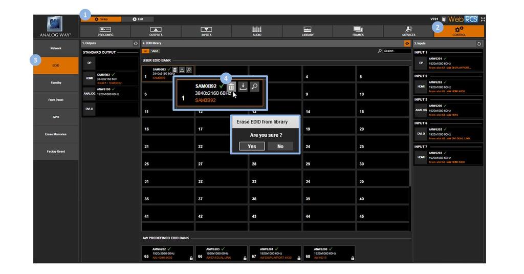
218 218
219 13 HDCP support 13.1 HDCP detection The VIO 4K is compliant with the HDCP specification for DVI, HDMI and DisplayPort input and output plugs. INPUT DETECTION On DVI, HDMI and DisplayPort input plugs, the HDCP detection is automatically managed by the input components. OUTPUT DETECTION On DVI-I (digital part only), HDMI and DisplayPort output plugs, the HDCP detection is automatically managed according to one of the following criteria: Hot plug 3-second period attempt 13.2 HDCP negotiation By default, the HDCP detection is enabled on all input and output plugs that support the HDCP specification (SEE: HDCP detection). If an input source is HDCP-encrypted, the output availability is then negotiated according to the following criteria: HDCP output peripheral Non-HDCP output peripheral HDCP source (*) Output content is available only if HDCP is enabled on both the input and output plugs. Output is blackened even if HDCP is enabled on the output plug. (*) Only on video plugs standard that support HDCP (HDMI, DisplayPort, DVI). Non-HDCP source Output content is available, whichever the status on the output plug. By enabling and disabling HDCP, you can thus relatively control the whole HDCP stream: Input control With HDCP enabled (default), the HDCP negotiation is maintained even if the DVI, HDMI or DisplayPort plug is not the current plug (active input). With HDCP disabled, none of the HDCP sources can be displayed (the sources will see the VIO 4K inputs as non-hdcp compliant). 219
220 Output control With HDCP enabled (default), the HDCP encryption is maintained whether the screen is compliant or not. With HDCP disabled, all screens are seen as non-hdcp compliant. TIP: Disable HDCP as much as possible, especially if not using HDCP-encrypted sources Managing HDCP To check the HDCP status of an input plug: 1. Enter the INPUTS menu on the interface. 2. Scroll down and select an input to access the selected input setup menu. TIP: Double-click on an INPUT SELECTION button to shortcut to the input setup menu directly. 3. Select the plug settings to access the input plug settings menu. 4. Select Status to check the input plug status. 5. Under Format > HDCP, check the HDCP status of the input plug. TIP: Go to the CUSTOMIZE menu and select HDCP Manager to manage HDCP on all input plugs. 1. Go to the Setup menu on the interface. 2. Click on the INPUTS tab to access the inputs setup page. 3. In the left side toolbar, select an input to access the selected input setup page. 4. Select the Signal tab to access the plug settings page. 5. Under HDCP, check the HDCP status of the input plug. 220
221 TIP: Use the Quick Setup button (located at the bottom of the interface) to manage HDCP on all input plugs. To enable/disable HDCP on an input plug: NOTE: With HDCP enabled (default), the HDCP negotiation is maintained even if the DVI, HDMI or DisplayPort plug is not the current plug (active input). With HDCP disabled, none of the HDCP sources can be displayed. 1. Enter the INPUTS menu on the interface. 2. Scroll down and select an input to access the selected input setup menu. TIP: Double-click on an INPUT SELECTION button to shortcut to the input setup menu directly. 3. Select the plug settings to access the input plug settings menu. 4. Scroll down and uncheck the HDCP check-box to disable HDCP on the input plug (check to enable). TIP: Go to the CUSTOMIZE menu and select HDCP Manager to manage HDCP on all input plugs. 1. Go to the Setup menu on the interface. 2. Click on the INPUTS tab to access the inputs setup page. 3. In the left side toolbar, select an input to access the selected input setup page. 4. Select the Signal tab to access the plug settings page. 5. Under HDCP, uncheck the Enable check-box to disable HDCP on the input plug (check to enable). 221
, the HDCP encryption is maintained whether the screen is compliant or not.")
222 TIP: Use the Quick Setup button (located at the bottom of the interface) to manage HDCP on all input plugs. To enable/disable HDCP on an output plug: NOTE: With HDCP enabled (default), the HDCP encryption is maintained whether the screen is compliant or not. With HDCP disabled, all screens are seen as non-hdcp compliant. 1. Enter the OUTPUTS menu on the interface. 2. Select STANDARD OUTPUT to access the standard output setup menu. 3. Select Plug Settings to access the plug setup menu for the output. 4. Select a plug to access the selected plug setup menu. 5. Check the HDCP Detection check-box to enable the HDCP negotiation on the output plug (uncheck to disable). TIP: Go to the CUSTOMIZE menu and select HDCP Manager to manage HDCP on all input plugs. 1. Go to the Setup menu on the interface. 2. Click on the OUTPUTS tab to access the outputs setup page. 3. In the left side toolbar, select STANDARD OUTPUT to access the standard output setup page. 4. Disable the Hide all plugs button if required to show the output plugs. 5. Click on the Show plugs settings button to access the plug settings for each output plug. 6. Locate the plug to set up. 7. Check the HDCP check-box to enable the HDCP negotiation on the output plug (uncheck to disable). 222
 to manage HDCP on all output plugs.")
223 TIP: Use the Quick Setup button (located at the bottom of the interface) to manage HDCP on all output plugs. 223
1 81 89 08 60 Fax: +33 (0)1 57 19 04 54 2/4 rue Georges Besse 92160 Antony FRANCE Analog Way Inc. Tel.")
224 CONTACT INFORMATION The Americas Europe, Middle East & Africa Asia Pacific Analog Way SAS - Headquarters Tel.: +33 (0) Fax: +33 (0) /4 rue Georges Besse Antony FRANCE Analog Way Inc. Tel.: Toll free: Fax: Summer Oak Place Buford, GA USA Analog Way Pte Ltd Tel.: Fax: Beach Road #15-03 Gateway East SINGAPORE Sales/General information: saleseuro@analogway.com Sales/General information: salesusa@analogway.com Sales/General information: sales@analogwayasia.com Technical support: techsupport@analogway.com Tel.: +33 (0) Technical support: techsupportusa@analogway.com Technical support: techsupport@analogwayasia.com Analog Way Germany Tel.: salesgermany@analogway.com Analog Way Italy Tel.: salesitaly@analogway.com Analog Way UK Tel.: +44 (0) salesuk@analogway.com 224

225 225
FS1-X. Quick Start Guide. Overview. Frame Rate Conversion Option. Two Video Processors. Two Operating Modes
 FS1-X Quick Start Guide Overview Matching up and synchronizing disparate video and audio formats is a critical part of any broadcast, mobile or post-production environment. Within its compact 1RU chassis,
FS3. Quick Start Guide. Overview. FS3 Control
 FS3 Quick Start Guide Overview The new FS3 combines AJA's industry-proven frame synchronization with high-quality 4K up-conversion technology to seamlessly integrate SD and HD signals into 4K workflows.
FS4 Quick Start Guide
 FS4 Quick Start Guide Overview FS4 is AJA s flagship frame synchronizer and converter, offering incredible versatility and connectivity in a sleek and compact 1RU frame for all your 4K/ UltraHD/2K/HD/SD
U S E R G U I D E HD1000
 U S E R G U I D E HD1000 1 W e l c o m e t o R o k u! In This Guide... Bring your HDTV to life with Roku. For the first time, you ll enjoy viewing your favorite digital photos in high-definition on your
Broadcast A/V Division M-LYNX-702 V.3. Dual 7 LCD Display. User Manual
 Broadcast A/V Division M-LYNX-702 V.3 Dual 7 LCD Display User Manual 1. Package Includes Table of Contents 1. Package Includes Table of Contents 01 02 One M-LYNX-702 Monitor One universal AC power adapter
EEG A1452 SCTE-104 Inserter Frame Card
 EEG A1452 SCTE-104 Inserter Frame Card Product Manual EEG Enterprises, Inc. 586 Main Street Farmingdale, New York 11735 TEL: (516) 293-7472 FAX: (516) 293-7417 Copyright EEG Enterprises, Inc. 2017 All
User Manual. Multi-Screen Splicing Processor J6
 User Manual Multi-Screen Splicing Processor J6 Rev1.0.0 NS160100147 Statement Dear users, Welcome to use the J6, a multi-screen splicing processor. This manual is intended to help you to understand and
Broadcast A / V Division M-LYNX-702 V.3. Dual 7 LCD Display. User Manual
 Broadcast A / V Division M-LYNX-702 V.3 Dual 7 LCD Display User Manual Table of Contents Table of Contents 1. Package Includes 2. Product Description 2.1 Front Panel 2.2 Rear Panel Connections 3. On-Screen
CI-218 / CI-303 / CI430
 CI-218 / CI-303 / CI430 Network Camera User Manual English AREC Inc. All Rights Reserved 2017. l www.arec.com All information contained in this document is Proprietary Table of Contents 1. Overview 1.1
J6 User Manual. User Manual. Multi-Screen Splicing Processor J6. Xi an NovaStar Tech Co., Ltd. Rev1.0.1 NS
 J6 User Manual User Manual Multi-Screen Splicing Processor J6 Rev1.0.1 NS160110162 Statement Dear users, You are welcome to use the J6, a multi-screen splicing processor of Xi'an NovaStar Tech Co., Ltd.
Operating Instructions
 Marshall Electronics Broadcast A/V Division Model No. VSW-2200 4-Input Seamless SDI A/V Switcher Operating Instructions Table of Contents 1. Overview... 2. Features.... Package Contents... 4. Specifications...
Manual Version Ver 1.0
 The BG-3 & The BG-7 Multiple Test Pattern Generator with Field Programmable ID Option Manual Version Ver 1.0 BURST ELECTRONICS INC CORRALES, NM 87048 USA (505) 898-1455 VOICE (505) 890-8926 Tech Support
DINOX&Digital&Video&Recorder&
 DINOX&Digital&Video&Recorder& & & & & & & & & & &&&Quick&Operation&Guide& UD.7L0X02B1228B01& Thank you for purchasing our product. If there is any question or request, please do not hesitate to contact
Digital Video Recorder
 Digital Video Recorder Quick Operation Guide UD.6L0202B0067A02 Thank you for purchasing our product. If there is any question or request, please do not hesitate to contact dealer. This manual is applicable
VSP 198CVS Quick Start
 VIEWSIZE THE WORLD VSP 198CVS Quick Start Max 2048 1152@60Hz/2560 1152 50Hz input/output resolution User customize output resolution 3G/HD/SD-SDI input Multiple cascade mapping for super resolution DVI
USER MANUAL. MODEL: VS-44UHDA 4x4 UHD Matrix Switcher. P/N: Rev 1
 USER MANUAL MODEL: VS-44UHDA 4x4 UHD Matrix Switcher P/N: 2900-300641 Rev 1 www.kramerav.com Contents Introduction 1 Getting Started 1 Overview 2 Typical Applications 3 Controlling your VS-44UHDA 3 Defining
Statement SmartLCT User s Manual Welcome to use the product from Xi an NovaStar Tech Co., Ltd. (hereinafter referred to as NovaStar ). It is our great
. It is our great") LED Display Configuration Software SmartLCT User s Manual Software Version: V3.0 Rev3.0.0 NS110100239 Statement SmartLCT User s Manual Welcome to use the product from Xi an NovaStar Tech Co., Ltd. (hereinafter
LED Display Configuration Software SmartLCT User s Manual Software Version: V3.0 Rev3.0.0 NS110100239 Statement SmartLCT User s Manual Welcome to use the product from Xi an NovaStar Tech Co., Ltd. (hereinafter
QuadView UHD 4K Multiviewer User s Guide
 SPECTRUM QuadView UHD 4K Multiviewer User s Guide August 2016 Spectrum 950 Marina Village Parkway Alameda, CA 94501 DOCUMENT QuadView UHD User's Guide P/N 350-11845-01 v1.0 August 2016 COPYRIGHT 2015-2016
EdgeConnect Module Quick Start Guide ITERIS INNOVATION FOR BETTER MOBILITY
 EdgeConnect Module Quick Start Guide ITERIS INNOVATION FOR BETTER MOBILITY 493456301 Rev B April 2009 Table of Contents Installation... 1 Setup... 2 Operation... 4 Live Video... 4 Video Settings... 5 Network
Globalmediapro SMR-650
 Globalmediapro SMR-650 16 x 16 Modularized Hybrid 3G-SDI Matrix Operation Manual CONTENTS 1. Introduction... 1 2. Applications... 1 3. Package Contents... 1 4. System Requirements... 1 5. Features... 2
IP LIVE PRODUCTION UNIT NXL-IP55
 IP LIVE PRODUCTION UNIT NXL-IP55 OPERATION MANUAL 1st Edition (Revised 2) [English] Table of Contents Overview...3 Features... 3 Transmittable Signals... 3 Supported Networks... 3 System Configuration
OPERATING GUIDE. HIGHlite 660 series. High Brightness Digital Video Projector 16:9 widescreen display. Rev A June A
 OPERATING GUIDE HIGHlite 660 series High Brightness Digital Video Projector 16:9 widescreen display 111-9714A Digital Projection HIGHlite 660 series CONTENTS Operating Guide CONTENTS About this Guide...
VIDEO GRABBER. DisplayPort. User Manual
 VIDEO GRABBER DisplayPort User Manual Version Date Description Author 1.0 2016.03.02 New document MM 1.1 2016.11.02 Revised to match 1.5 device firmware version MM 1.2 2019.11.28 Drawings changes MM 2
Operating Instructions
 Broadcast A/V Division Model No. M-LYNX-702W Dual 7 High Resolution Rack Mount Display with Waveform Operating Instructions V.1.0 Table of Contents 1. PRODUCT DESCRIPTION... 3 2. MENU SETTING... 6 3. SPECIFICATIONS...
ivw-ud322 / ivw-ud322f
 ivw-ud322 / ivw-ud322f Video Wall Controller Supports 2 x 2, 2 x 1, 3 x 1, 1 x 3, 4 x 1 & 1 x 4 Video Wall Array User Manual Rev. 1.01 i Notice Thank you for choosing inds products! This user manual provides
Viewing Set-Top Box Data
 Device View, page 1 Alerts, page 3 Device Properties, page 3 Quick Actions, page 3 View Log Entries, page 4 Monitor STB Connectivity, page 5 Device View Note While every possible effort has been made to
Operation Guide Version 2.0, December 2016
 Operation Guide Version 2.0, December 2016 Document Revision History Revision Date Description v1.0 January 8, 2016 Initial release of COLR Operation Manual, based on firmware version 1.0.1 CONTENTS Contents...
C8188 C8000 1/10. digital audio modular processing system. 4 Channel AES/EBU I/O. features. block diagram. 4 balanced AES inputs
 features 4 balanced AES inputs Input Sample Rate Converters (SRC) 4 balanced AES outputs Relay bypass for pairs of I/Os Relay wait time after power up Master mode (clock master for the frame) 25pin Sub-D,
HD4112 Quad HDMI MPEG2 HD DVBT Encoder Modulator U S E R M A N U A L
 HD4112 Quad HDMI MPEG2 HD DVBT Encoder Modulator U S E R M A N U A L HD4112 Manual Rev 1 Contents 1. GENERAL 1.1 Description 1.2 Specifications 2. INSTALLATION 2.1 What s in the Box 2.2 Connection 2.2.1
Part 1 Basic Operation
 This product is a designed for video surveillance video encode and record, it include H.264 video Compression, large HDD storage, network, embedded Linux operate system and other advanced electronic technology,
V pro8 QUICK START GUIDE
 QUICK START GUIDE Welcome to your V pro8 FIRST STEPS POWERING ON CONNECTING YOUR COMPUTER Thank you for buying the Lawo V pro8, a true high-quality product developed and manufactured in Rastatt, Germany.
C8000. sync interface. External sync auto format sensing : AES, Word Clock, Video Reference
 features Standard sync module for a frame Internal sync @ 44.1 / 48 / 88.2 / 96kHz External sync auto format sensing : AES, Word Clock, Video Reference Video Reference : Black Burst (NTSC or PAL) Composite
CONTENT Product Introduction... 2 Packing Configuration...3 Hardware Orientation... 4 Front Panel... 4 Back Panel... 6 Using Your Product... 7 Content
 VENUS X1PRO Quick Start 4K input support in DP, HDMI and DVI Input standard 2K formats Scale and switch seamlessly between 2K and 4K inputs Output to any format 2K or 4K EDID management on board HDCP 2.0
CCE900-IP-TR. User s Guide
 CCE900-IP-TR CCE900-IP-T & CCE900-IP-R User s Guide i-tech Company LLC TOLL FREE: (888) 483-2418 EMAIL: info@itechlcd.com WEB: www.itechlcd.com 1. Introduction The CCE900-IP-T & CCE900-IP-R is a solution
AV Foundry VideoForge HDMI Digital Video Generator Quick Start Guide
 AV Foundry VideoForge HDMI Digital Video Generator Quick Start Guide Thank you for purchasing an AV Foundry VideoForge HDMI Digital Video Generator, a versatile, high value test pattern generator with
DB-VRC4H 4K HDMI Compact Video Wall Controller with 45 degree screen rotation
 DB-VRC4H 4K HDMI Compact Video Wall Controller with 45 degree screen rotation The DigiBird DB-VRC4H Video Wall Controller is the simplest and most cost-effective solution to build an eyecatching and creative
DS-7200HVI/HFI-SH Series DVR Quick Operation Guide
 DS-7200HVI/HFI-SH Series DVR Quick Operation Guide UD.6L0202B0019A01 Thank you for purchasing our product. If there is any question or request, please do not hesitate to contact dealer. This manual is
Transmitter Interface Program
 Transmitter Interface Program Operational Manual Version 3.0.4 1 Overview The transmitter interface software allows you to adjust configuration settings of your Max solid state transmitters. The following
Copyright 2018 Xi an NovaStar Tech Co., Ltd. All Rights Reserved. No part of this document may be copied, reproduced, extracted or transmitted in any
 MCTRL660 PRO Independent Controller Product Version: Document Number: V1.0.0 NS110100560 Copyright 2018 Xi an NovaStar Tech Co., Ltd. All Rights Reserved. No part of this document may be copied, reproduced,
HDMI 2.0 Multiview Video Processor
 Product Data HDMI 2.0 Multiview Video Processor VP-QV41 Introduction The Partilink VP-QV41 Multiview Video Processor is a simple, cost-effective video scaler designed to enable a 4K@60Hz, HD, SD computer
Marshall Electronics. Operating Instructions. Warranty. Model No. QVW Quad-Viewer Monitor with 4K Format Support
 Warranty Marshall Electronics warranties to the first consumer that this QVW-2710 LCD monitor will, under normal use, be free from defects in workmanship and materials, when received in its original container,
T2210HD/T2210HDA 21.5 Wide-Screen LCD Monitor User Manual
 T2210HD/T2210HDA 21.5 Wide-Screen LCD Monitor User Manual Table of Contents Package contents...3 Installation...4 To connect the monitor to your PC... 4 Adjusting your monitor...5 Functions of the buttons
User Guide Mix-iT.ATEM v2.0. September User Guide Mix-iT for ATEM v2.0
 User Guide Mix-iT.ATEM v2.0 September 2015-1- Declaration of Conformity We, manufacturer/representative ArtiVisuals Molukkenstraat 200 S3 1098 TW Amsterdam The Netherlands declare under our sole responsibility,
DVI-3580a. 4K MultiViewer Switcher / Scaler. Quick Start Guide. Introduction
 Quick Start Guide 4K MultiViewer Switcher / Scaler Introduction Presentation Powerhouse The is a high-performance 4K MultiViewer Switcher / Scaler. This unit is an ideal solution for system designers and
Quick Operation Guide of LTN7700/7600 Series NVR
 Quick Operation Guide of LTN7700/7600 Series NVR UD.6L0202B0042A02 Thank you for purchasing our product. If there is any question or request, please do not hesitate to contact dealer. This manual is applicable
G406 application note for projector
 G406 application note for projector Do you have trouble in using projector internal warp and edge blending function? Inconvenient in multiple signal source connection System resolution is not enough after
REMOTELY CONTROL SCANDO HD
 MANUAL REMOTELY CONTROL SCANDO HD DVI and Analog RGB Computer Video to 3G/HD/SD-SDI Scan Converter with Genlock Input and Fiber Optic Output Installation and Operations Manual WWW.ARTEL.COM Contents Introduction...
Cablecast Server. Setup Guide. c Tightrope Media Systems For Cablecast version Build 74
 Cablecast Server Setup Guide c Tightrope Media Systems For Cablecast version 6.1.2 Build 74 Printed July 22, 2016 1 Cablecast Server Setup 1.1 Prerequisites 1.2 Overview of Setup Thank you for purchasing
FS-HDR Quick Start Guide
 FS-HDR Quick Start Guide Overview FS-HDR, a 1RU, rack-mount, universal converter/frame synchronizer, is designed specifically to meet the HDR (High Dynamic Range) and WCG (Wide Color Gamut) needs of broadcast,
Operation Guide Version 1.0, December 2015
 Operation Guide Version 1.0, December 2015 Document Revision History Revision Date Description v1.0 January 8, 2016 Initial release of COLR Operation Manual, based on firmware version 1.0.1 CONTENTS Contents...
Z-IP Stream 004/008. User Guide and Installation Manual. Four or Eight Input QAM Encoder / Modulator
 Z-IP Stream 004/008 User Guide and Installation Manual Four or Eight Input QAM Encoder / Modulator MPEG-2 / H.264 HD ENCODER with QAM /IP/ & ASI Outputs Contents Safety Precautions... 3 Package Contents...
22" Touchscreen LED Monitor USER'S GUIDE
 22" Touchscreen LED Monitor USER'S GUIDE Content Operation Instructions...1 Unpacking Instructions...2 Safety Precautions...2 Front View of the Product...3 Rear View of the Product...4 Quick Installation...5
EDITION NOTES. Document Revision
 User Manual EDITION NOTES The VIP Drive 43Nova User Manual includes a description, safety precautions, installation, programming, operation, and maintenance instructions for the VIP Drive 43Nova as of
Multi-Screen Splicing Video Processor. Xi an NovaStar Tech Co., Ltd. Specifications. Document Version: Document Number:
 N9 Multi-Screen Splicing Video Processor Document Version: V1.0.0 Document Number: Copyright 2018 All Rights Reserved. No part of this document may be copied, reproduced, extracted or transmitted in any
C8491 C8000 1/17. digital audio modular processing system. 3G/HD/SD-SDI DSP 4/8/16 audio channels. features. block diagram
 features 4 / 8 / 16 channel LevelMagic2 SDI-DSP with level or loudness (ITU-BS.1770-1/ ITU-BS.1770-2, EBU R128) control 16 channel 3G/HD/SD-SDI de-embedder 16 in 16 de-embedder matrix 16 channel 3G/HD/SD-SDI
Syntor X Flash Memory Module Revision C
 Syntor X Flash Memory Module Revision C The PIEXX SynXFlash memory module, along with the supplied PC software, replaces the original SyntorX code plugs and allows you to easily set modify and update your
FS-HDR Quick Start Guide
 FS-HDR Quick Start Guide Overview FS-HDR, a 1RU, rack-mount, universal converter/frame synchronizer, is designed specifically to meet the HDR (High Dynamic Range) and WCG (Wide Color Gamut) needs of broadcast,
User s Manual. Network Board. Model No. WJ-HDB502
 Network Board User s Manual Model No. WJ-HDB502 Before attempting to connect or operate this product, please read these instructions carefully and save this manual for future use. CONTENTS Introduction...
E-MANUAL. Thank you for purchasing this Samsung product. To receive more complete service, please register your product at.
 E-MANUAL Thank you for purchasing this Samsung product. To receive more complete service, please register your product at www.samsung.com/register Model Serial No. Contents Quick Guides Using Smart Hub
NX-series User Manual
 NX-series User Manual http://www.iviewtech.com 1 CONTENT INDEX 1 NX-SERIES OVERVIEW... 4 1.1. NX-Series Features 4 1.2. NVR CONTROL PANEL 5 1.3. NVR BACK PANEL 5 2 GETTING STARTED... 8 3 LIVE VIEW... 10
Dell Wyse 5030 PCoIP Zero Client
 Dell Wyse 5030 PCoIP Zero Client User Guide Regulatory Model: PxN Regulatory Type: PxN001 Notes, cautions, and warnings NOTE: A NOTE indicates important information that helps you make better use of your
VENUS X1PRO-E Quick Start
 VENUS X1PRO-E Quick Start 4K input support in DP, HDMI and Dual Link DVI Support 8K x 1K, 4K x 2K Seamless Splicing EDID management Modular 2K input: Three slots for 2K input options 2K-2K and/or 4K-2K
Cablecast SX. Setup Guide. c Tightrope Media Systems For Cablecast version Build 206
 Cablecast SX Setup Guide c Tightrope Media Systems For Cablecast version 5.2.11 Build 206 Printed June 5, 2015 1 Cablecast SX Setup 1.1 Prerequisites 1.2 Overview of Setup Thank you for purchasing a Cablecast
Hardware Setup. If you have any further questions after checking this document, please contact
 Hardware Setup If you have any further questions after checking this document, please contact support@cognisens.com Hardware Setup Getting Started: NeuroTracker Pro WHAT TO BUY SETTING UP YOUR 3D TV SETTING
QUICK START GUIDE QT ANALOG HD CAMERA & DVR BUNDLE ENGLISH
 QUICK START GUIDE QT ANALOG HD CAMERA & DVR BUNDLE ENGLISH Table of Contents Welcome What s Included...3 Understanding your DVR...4 Get Connected Registration...5 Connect Your Cameras...5 Connect DVR to
Getting started with
 Getting started with Electricity consumption monitoring single phase for homes and some smaller light commercial premises OVERVIEW: The OWL Intuition-e electricity monitoring system comprises of three
FIRMWARE RELEASE NOTE
 Products VRC300 Date Nov 18, 2015 Version 2.02.08 The version(s) indicated here above has (have) been tested and validated by the Technical Support Department. Version 2.02.08 Technical notes New Features
C8000. switch over & ducking
 features Automatic or manual Switch Over or Fail Over in case of input level loss. Ducking of a main stereo or surround sound signal by a line level microphone or by a pre recorded announcement / ad input.
DTV742 Installation Quick Start Guide
 DTV742 Installation Quick Start Guide The Wegener Model DTV742 8VSB 4-Channel Multiplexor receives VHF/UHF broadcast HDTV signals and provides output ASI streams for connection to cable system QAM modulators.
Simple Media Platform Quick Installation Guide V1.0-N. Simple Media Platform. Quick Installation Guide
 Simple Media Platform Quick Installation Guide 1. Installation Instruction 1.1 Mounting unit to a 19 rack When selecting the installation site, try to comply with the following: Protective Ground - The
Package Contents. LED Protocols Supported. Safety Information. Physical Dimensions
 Pixel Triton Table of Contents Package Contents... 1 Safety Information... 1 LED Protocols Supported... 1 Physical Dimensions... 1 Software Features... 2 LED Status... 2 Power... 2 Activity LED... 2 Link
CH-U330TX & CH-U330RX 4K UHD Multi-Function Extender with Video over IP and KVM
 CH-U330TX & CH-U330RX 4K UHD Multi-Function Extender with Video over IP and KVM Operation Manual DISCLAIMERS The information in this manual has been carefully checked and is believed to be accurate. Cypress
Precautions and Disclaimers What You Can Do with Geometry Manager Pro Check Your Computer System requirements...
 Operating Instructions Geometric & Setup Management Software Windows Geometry Manager Pro Ver. 4.0 Thank you for purchasing this Panasonic product. Before using this software, please read the instructions
Video Extender DS128 DSRXL. Instruction Manual. 8-Port Cat5 VGA Digital Signage Broadcaster with RS232 and Audio
 DS128 DSRXL Instruction Manual Video Extender 8-Port Cat5 VGA Digital Signage Broadcaster with RS232 and Audio Cat5 VGA Digital Signage Receiver with RS232 and Audio FCC Compliance Statement This equipment
QUICK START GUIDE. QT Analog HD Camera & DVR Bundle ENGLISH
 QUICK START GUIDE QT Analog HD Camera & DVR Bundle ENGLISH Table of Contents Welcome What s Included...3 Understanding your DVR...4 Get Connected Registration...5 Connect Your Cameras...5 Connect DVR to
HD Leeza. Quick Setup Guide
 Page 1 of 15 Model KD-HD1080P Key Digital Video Processor Quick Setup Guide Have a question or a technical issue with your set-up? Call the Key Digital Hotline at: 866-439-8988 or 203-798-7187 E-mail the
Setup Guide. AV Foundry VideoForge HDMI. Digital Video Generator. Rev. 1.1
 Setup Guide AV Foundry VideoForge HDMI Digital Video Generator Rev. 1.1 Introduction The AV Foundry VideoForge HDMI Digital Video Generator is a versatile, high value test pattern generator with a field-ruggedized
E-MANUAL. Thank you for purchasing this Samsung product. To receive more complete service, please register your product at.
 E-MANUAL Thank you for purchasing this Samsung product. To receive more complete service, please register your product at www.samsung.com/register Model Serial No. Contents Connecting Antenna and External
HD-1603 Single Input MPEG-4 DVB-T HD Encoder/Modulator User Guide and Install Manual
 ZyCastR digi-mod HD Range digi-mod HD-1603 www.digi-modbyzycast.com HD-1603 Single Input MPEG-4 DVB-T HD Encoder/Modulator User Guide and Install Manual Table of Contents www.digi-modbyzycast.com Safety
INFORMATION TO USER CAUTION RISK OF ELECTRIC SHOCK, DO NOT OPEN
 INFORMATION TO USER CAUTION RISK OF ELECTRIC SHOCK, DO NOT OPEN! CAUTION: TO REDUCE THE RISK OF ELECTRIC SHOCK, DO NOT REMOVE COVER (OR BACK). NO USER SERVICEABLE PARTS INSIDE. REFER SERVICING TO QUALIFIED
TeamWork Kits Installation Guide
 TX 0 RX COM +5V APARATUS US TeamWork Kits Installation Guide TeamWork 400 and TeamWork 600 Kits The TeamWork 400 and TeamWork 600 kits consist of an HDMI switcher, system controller, Cable Cubby, and cables
Multi-format to HDMI scaler ID#15107
 Multi-format to HDMI scaler ID#15107 Operation Manual Introduction The Digital Video Scaler has CV, SV, HD, Composite, PC, HDMI and SDI inputs and can scale the signal into HDMI, VGA with audio output
CEDAR Series. To learn more about Ogden CEDAR series signal processing platform and modular products, please visit
 CEDAR Series The CEDAR platform has been designed to address the requirements of numerous signal processing modules. Easily-installed components simplify maintenance and upgrade. To learn more about Ogden
ivw-fd122 Video Wall Controller MODEL: ivw-fd122 Video Wall Controller Supports 2 x 2 Video Wall Array User Manual Page i Rev. 1.
 MODEL: ivw-fd122 Video Wall Controller Supports 2 x 2 Video Wall Array User Manual Rev. 1.01 Page i Copyright COPYRIGHT NOTICE The information in this document is subject to change without prior notice
Show Designer 3. Software Revision 1.15
 Show Designer 3 Software Revision 1.15 OVERVIEW... 1 REAR PANEL CONNECTIONS... 1 TOP PANEL... 2 MENU AND SETUP FUNCTIONS... 3 CHOOSE FIXTURES... 3 PATCH FIXTURES... 3 PATCH CONVENTIONAL DIMMERS... 4 COPY
DM-TX-201-C DigitalMedia 8G+ Transmitter. Supplemental Guide Crestron Electronics, Inc.
 DM-TX-201-C DigitalMedia 8G+ Transmitter Supplemental Guide Crestron Electronics, Inc. The product warranty can be found at www.crestron.com/warranty. The specific patents that cover Crestron products
P-2 Installing the monitor (continued) Carry out as necessary
 Carry out as necessary") P-2 Installing the monitor (continued) Carry out as necessary Using the monitor without the bezel MDT552S satisfies the UL requirements as long as it is used with the bezel attached. When using the monitor
P-2 Installing the monitor (continued) Carry out as necessary Using the monitor without the bezel MDT552S satisfies the UL requirements as long as it is used with the bezel attached. When using the monitor
Software Quick Manual
 XX177-24-00 Virtual Matrix Display Controller Quick Manual Vicon Industries Inc. does not warrant that the functions contained in this equipment will meet your requirements or that the operation will be
QUICK START GUIDE MODEL : PHD-VRX2
 Full HD 1080p Dual Tuner Digital HDTV Recorder, Receiver and Media Center Box QUICK START GUIDE MODEL : PHD-VRX2 Copyright 2013, PrimeDTV Technologies, Inc. Front View Menu: Display On-screen (OSD) Main
Projector Management Application Version 7.00 Instruction Guide
 Projector Management Application Version 7.00 Instruction Guide Contents 1 INTRODUCTION... 4 1.1 OUTLINE... 4 1.2 SYSTEM... 4 2 INSTALLATION... 5 2.1 SYSTEM REQUIREMENTS... 5 2.2 PROJECTOR MANAGEMENT APPLICATION
Installation and Operation Manual. ATEM Television Studio Switchers
 Installation and Operation Manual ATEM Television Studio Switchers March 08 English Welcome Thank you for purchasing an ATEM switcher for your live production work! If you re new to live production switchers,
RMS 8424S Quick Start
 VIEWSIZE THE WORLD RMS 8424S Quick Start Standard 4 unit rack mount size 8 inch LCD 2 1024 3 (RGB) 600 16:9 / 4:3 adjustable SDI/HDMI embedded audio output via 3.5mm earphone socket Support SDI/DVI audio
Pacific C-A Feature Highlights
 Pacific C-A Feature Highlights All-in-one, multi-format signal converter with scaler, up/down converting extensive range of graphics and video signals to designated signal format. Automatic sensing of
Marshall Electronics. Pro A/V Communications VMV-402-SH. 3G/HD/SD-SDI Quad-viewer/Switcher with Audio Meter Display. User Manual.
 Marshall Electronics Pro A/V Communications VMV-402-SH 3G/HD/SD-SDI Quad-viewer/Switcher with Audio Meter Display User Manual Table of Contents 1. Introduction... 3 2. Features... 3 3. Package Contents...
GV-3D People Counter 3DPCV10-A
 GV-3D People Counter User's Manual Before attempting to connect or operate this product, please read these instructions carefully and save this manual for future use. 3DPCV10-A 2013 GeoVision, Inc. All
User Instruction Manual IQSDA30/IQSDA32. Intelligent Reclocking High Performance HD-SDI/SD-SDI Distribution Amplifiers. snellgroup.
 User Instruction Manual IQSDA30/IQSDA32 Intelligent Reclocking High Performance HD-SDI/SD-SDI Distribution Amplifiers snellgroup.com IQSDA30/IQSDA32 www.snellgroup.com Information and Notices Information
BY-HPE11KTA. Operating Instructions. Coaxial - LAN Converter with PoE function. Indoor Use Only. Model No. Attached Installation Guide
 Operating Instructions Coaxial - LAN Converter with PoE function Model No. Indoor Use Only BY-HPE11KTA Attached Installation Guide Before attempting to connect or operate this product, please read these
DVB-T USB SET-TOP BOX
 DVB-T USB SET-TOP BOX User Manual Version: 1.0 (February 2005) TRANSYSTEM INC. No.1-2 Li-Hsin Rd.I Science-Based Industrial Park, Hsinchu, Taiwan Tel:+886-3-5780393 Fax:+886-3-5784111 e-mail: sales@transystem.com.tw
USER GUIDE /4-16/9047
 USER GUIDE 171951/4-16/9047 May 2016 CONTENTS Equipment 4 Connected-Home DVR/Standard Set-Top Box Wireless Set-Top Box Wireless Access Point Remote Controls Residential Gateway Getting Started 12 Turn
DRAFT RELEASE FOR BETA EVALUATION ONLY
 IPM-16 In-Picture Audio Metering User Manual DRAFT RELEASE FOR BETA EVALUATION ONLY Ver 0.2 April 2013 1 Contents Introduction...3 In Picture Audio Meter Displays...4 Installation...7 External Audio Board