R&S CMW270 Wireless Connectivity Tester Specifications
|
|
|
- Annabelle Kellie Flynn
- 6 years ago
- Views:
Transcription
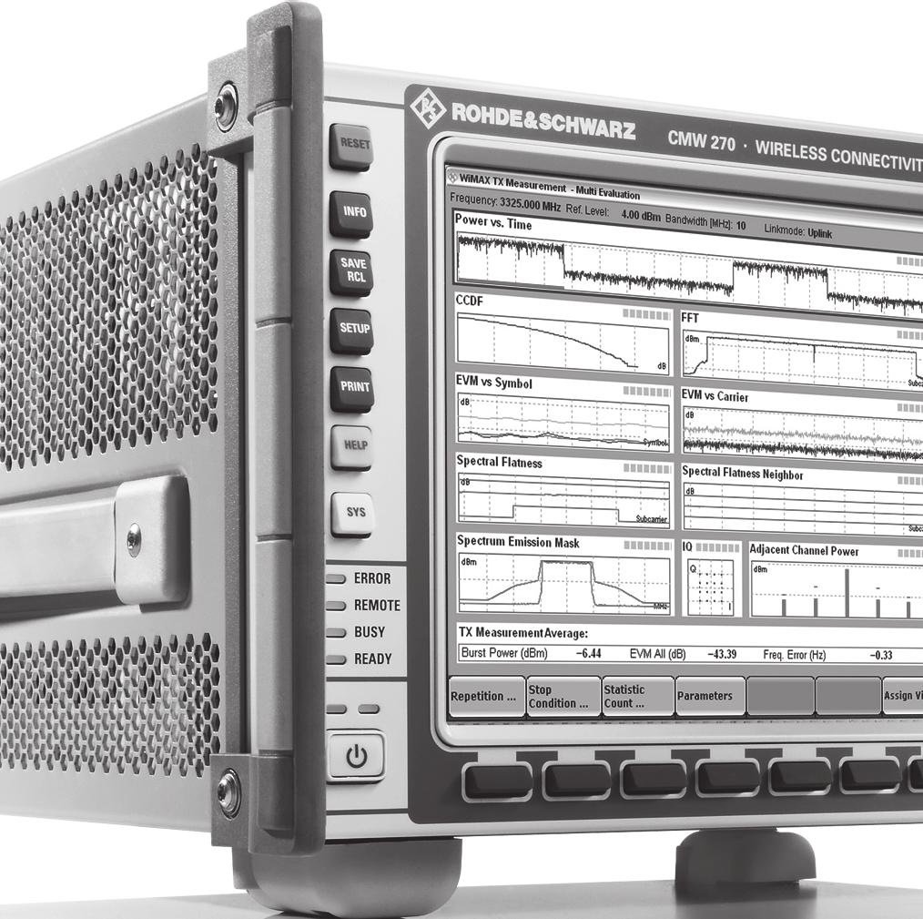
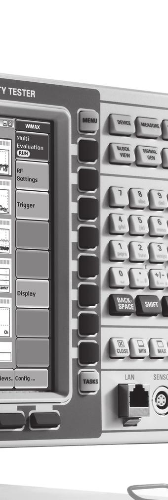
1 Titel CMW270_dat-sw_en_v0600.indd 1 Data Sheet Test & Measurement R&S CMW270 Wireless Connectivity Tester Specifications :43:02
2 CONTENTS General technical specifications... 5 RF generator...5 Modulation source: arbitrary waveform generator (ARB) (R&S CMW-B110A option)...7 RF analyzer...7 Power meter...8 Spectrum measurements...9 RF path 2 with RF TRX (R&S CMW-B570 option) and RF frontend (BASIC) (R&S CMW-B590A option)...9 Timebase...10 Timebase TCXO...10 Timebase basic OCXO (R&S CMW-B690A option)...10 Timebase highly stable OCXO (R&S CMW-B690B option)...10 Reference frequency inputs/outputs...10 Bluetooth specifications Bluetooth RF generator (prerequisite: R&S CMW-B110A option)...11 Bluetooth WINIQSIM2 (R&S CMW-KW610 option)...11 Bluetooth RF analyzer (R&S CMW-KM610 option)...11 Modulation analysis...12 GPS specifications GPS RF generator (prerequisite: R&S CMW-B110A option)...13 GPS WINIQSIM2 (R&S CMW-KW620 option)...13 DVB specifications DVB RF generator (prerequisite: R&S CMW-B110A option)...13 DVB WINIQSIM2 (R&S CMW-KW630 option)...13 FM STEREO RADIO specifications FM STEREO RADIO generator (prerequisite: R&S CMW-B110A option)...13 FM STEREO RADIO waveforms (R&S CMW-KV645 option)...13 FM STEREO RADIO analyzer (R&S CMW-KM645 option)...14 Audio filter, weighting...14 RF carrier analysis...14 Modulation analysis Rohde & Schwarz R&S CMW270 Wireless Connectivity Tester
3 WLAN specifications WLAN RF generator (prerequisite: R&S CMW-B110A option)...15 WLAN ABG WINIQSIM2 (R&S CMW-KW650 option)...15 WLAN N WINIQSIM2 (R&S CMW-KW651 option)...15 WLAN ABG RF analyzer (R&S CMW-KM650 option)...15 Modulation analysis...16 Spectrum measurements...17 WLAN N RF analyzer (R&S CMW-KM651 option)...17 Modulation analysis...17 Spectrum measurements...18 WiMAX specifications mobile station and base station test WiMAX RF generator (prerequisite: R&S CMW-B110A option)...19 WiMAX WINIQSIM2 (R&S CMW-KW700 option)...19 WiMAX RF analyzer (R&S CMW-KM700, R&S CMW-KM701 options)...19 Power measurement...20 Modulation analysis...20 Spectrum measurements...21 WiMAX signaling base station emulator (prerequisite: R&S CMW-KS700, R&S CMW-KS701, R&S CMW-KS702, R&S CMW- B200A, R&S CMW-B270A options)...21 Physical layer...21 Measurements...22 Features...22 WiMAX IP application enabler (prerequisite: R&S CMW-KA700, R&S CMW-B660, R&S CMW-B661 options)...23 Digital I/Q 1 to 4 (R&S CMW-B510A option)...24 Digital I/Q interface...24 AUX interface...24 Included extras...24 General data Ordering information Recommended extras for manual operation...27 Recommended extras...27 Rohde & Schwarz R&S CMW270 Wireless Connectivity Tester 3
4 Specifications apply under the following conditions: Data valid for the R&S CMW270 unless otherwise stated. Data without tolerance limits is not binding. Based on a 24-month calibration interval unless otherwise stated. At least 15 minutes warm-up time at ambient temperature, specified environmental conditions met, calibration cycle adhered to, and all internal automatic adjustments performed. "Typical values" are designated with the abbreviation "typ.". These values are verified during the final test but are not assured by Rohde & Schwarz. "Nominal values" are design parameters that are not assured by Rohde & Schwarz. These values are verified during product development but are not specifically tested during production. In line with the 3GPP/3GPP2 standard, chip rates are specified in Mcps (million chips per second), whereas bit rates and symbol rates are specified in Mbps (million bits per second), kbps (thousand bits per second) or ksps (thousand symbols per second), and sample rates are specified in Msample/s (million samples per second). Mcps, kbps, ksps and Msample/s are not SI units During the production process, each instrument is calibrated in line with defined procedures. All measurement results, including measurement uncertainties of the calibration system, have to be within the published specification limits to release the individual instrument. The expanded measurement uncertainties of the calibration system used in the production process are determined with a coverage factor of k = 2 (normally approx. 95 % probability). Parameters written in italics can be set directly on the tester. "WiMAX Forum" is a registered trademark of the WiMAX Forum. "WiMAX," the WiMAX Forum logo, "WiMAX Forum Certified," and the WiMAX Forum Certified logo are trademarks of the WiMAX Forum. The Bluetooth word mark and logos are registered trademarks owned by Bluetooth SIG, Inc. and any use of such marks by Rohde & Schwarz is under license. Data without tolerance limits is not binding. 4 Rohde & Schwarz R&S CMW270 Wireless Connectivity Tester
5 General technical specifications RF generator Frequency range Frequency resolution Frequency uncertainty Output level range RF1 OUT 70 MHz to 100 MHz continuous wave (CW) peak envelope power (PEP) overranging (PEP) 100 MHz to 3300 MHz continuous wave (CW) peak envelope power (PEP) overranging (PEP) 3300 MHz to 6000 MHz continuous wave (CW) peak envelope power (PEP) overranging (PEP) maximum input DC level 70 MHz to 100 MHz continuous wave (CW) peak envelope power (PEP) overranging (PEP) 100 MHz to 3300 MHz continuous wave (CW) peak envelope power (PEP) overranging (PEP) 3300 MHz to 6000 MHz continuous wave (CW) peak envelope power (PEP) overranging (PEP) maximum input DC level 70 MHz to 3300 MHz up to 6000 MHz with the R&S CMW-KB036 option 0.1 Hz same as timebase + frequency resolution 130 dbm to 15 dbm up to 15 dbm up to 10 dbm 130 dbm to 5 dbm up to 5 dbm up to 0 dbm 120 dbm to 15 dbm up to 15 dbm up to 10 dbm 0 V DC 120 dbm to 2 dbm up to 2 dbm up to +3 dbm 120 dbm to +8 dbm up to +8 dbm up to +13 dbm 110 dbm to 2 dbm up to 2 dbm up to +3 dbm 0 V DC Output level uncertainty RF1 OUT Output level uncertainty RF1 OUT in temperature range +20 C to +35 C, no overranging output level > 120 dbm 70 MHz to 100 MHz < 1.2 db MHz to 3300 MHz < 0.6 db MHz to 6000 MHz < 1.2 db 1 output level > 110 dbm 70 MHz to 100 MHz < 1.6 db MHz to 3300 MHz < 0.8 db MHz to 6000 MHz < 1.6 db 1 in temperature range +5 C to +45 C, no overranging output level > 120 dbm 70 MHz to 100 MHz < 2.0 db MHz to 3300 MHz < 1.0 db MHz to 6000 MHz < 2.0 db 1 output level > 110 dbm 70 MHz to 100 MHz < 2.0 db MHz to 3300 MHz < 1.0 db MHz to 6000 MHz < 2.0 db 1 1 Valid for a 12-month calibration interval. Rohde & Schwarz R&S CMW270 Wireless Connectivity Tester 5
6 Output level linearity with fixed RF output attenuator setting in temperature range +20 C to +35 C, GPRF generator list mode, level range 0 db to 30 db no overranging < 0.2 db, typ. < 0.1 db Output level resolution Output level repeatability typical values after 1 h warm-up time, always returning to same level and frequency, no temperature change, insignificant time change output level 80 dbm output level < 80 dbm 0.01 db < 0.01 db < 0.05 db VSWR RF1 OUT 70 MHz to 3300 MHz < MHz to 5000 MHz < MHz to 6000 MHz < MHz to 3300 MHz < MHz to 5000 MHz < MHz to 6000 MHz < 1.6 Attenuation of 2nd harmonic 70 MHz to 6000 MHz, P < 10 dbm > 30 db RF1 OUT 70 MHz to 6000 MHz, P < 0 dbm > 30 db Attenuation of 3rd harmonic 70 MHz to 6000 MHz, P < 10 dbm > 40 db RF1 OUT 70 MHz to 6000 MHz, P < 0 dbm > 40 db Attenuation of nonharmonics > 5 khz offset from carrier, for output level > 40 dbm, for full scale CW signal 400 MHz to 3300 MHz, > 60 db except f nonharmonic = 3900 MHz f carrier, except f nonharmonic = 3900 MHz except f carrier = (899 to 901) MHz + n 800 MHz with n = 1, 2, MHz to 3600 MHz > 25 db 3600 MHz to 6000 MHz, > 40 db except f nonharmonic = 2 f carrier 6400 MHz Phase noise single sideband, 70 MHz to 3300 MHz Carrier offset 1 MHz < 120 dbc, 1 Hz Phase noise single sideband, 3300 MHz to 6000 MHz Carrier offset 1 MHz < 117 dbc, 1 Hz Signal-to-noise ratio 70 MHz to 3300 MHz 5 MHz offset from carrier, for output level > 30 dbm > 95 db, typ. > 101 db, 1 khz (> 125 db, typ. > 131 db, 1 Hz) Signal-to-noise ratio 3300 MHz to 6000 MHz 5 MHz offset from carrier, for output level > 30 dbm > 92 db, 1 khz 6 Rohde & Schwarz R&S CMW270 Wireless Connectivity Tester
7 Modulation source: arbitrary waveform generator (ARB) (R&S CMW-B110A option) Memory size Gbyte Word length I 16 bit Q 16 bit marker 4 bit to 16 bit Sample length with 4-bit marker up to Msample Sample rate minimum 400 Hz maximum 100 MHz Trigger Trigger sources BASE: external TRIG A, BASE: external TRIG B RF analyzer VSWR 70 MHz to 3300 MHz < MHz to 5000 MHz < MHz to 6000 MHz < 1.6 Inherent spurious response without input signal 70 MHz to 6000 MHz, except 4000 MHz, 4800 MHz, 5600 MHz, 6000 MHz < 100 dbm Spurious response Harmonic response Harmonic response for full scale single tone input signal 70 MHz to 3300 MHz except f in = MHz and 3925 MHz 3300 MHz to 3700 MHz, except f in = 6400 MHz f selected, except f in = 6400 MHz 0.5 f selected 3700 MHz to 6000 MHz, except f in = 6400 MHz 0.5 f selected 2nd harmonic f in = 70 MHz to 1650 MHz, f selected = 140 MHz to 3300 MHz f in = 1650 MHz to 3000 MHz, f selected = 3300 MHz to 6000 MHz 3rd harmonic f in = 70 MHz to 1100 MHz, f selected = 210 MHz to 3300 MHz f in = 1100 MHz to 2000 MHz, f selected = 3300 MHz to 6000 MHz < 55 db < 40 db < 40 db < 30 db < 30 db < 50 db < 50 db Phase noise single sideband, 70 MHz to 3300 MHz Carrier offset 1 MHz < 120 dbc, 1 Hz Phase noise single sideband, 3300 MHz to 6000 MHz Carrier offset 1 MHz < 117 dbc, 1 Hz Trigger Trigger sources BASE: external TRIG A, BASE: external TRIG B, GPRF: free run, GPRF: IF power, BB generators, BB signaling Rohde & Schwarz R&S CMW270 Wireless Connectivity Tester 7
8 Power meter Frequency range Frequency resolution Resolution bandwidths Expected nominal power setting range Level range 70 MHz to 3300 MHz up to 6000 MHz with the R&S CMW-KB036 option 0.1 Hz Gaussian, 1 khz to 10 MHz, in 1/3/5 steps, bandpass, 1 khz to 30 MHz, in 1/3/5 steps, RRC, α = 0.1, 3.84 MHz, RRC, α = 0.22, WCDMA filter, MHz, CDMA filter for ADC full scale 70 MHz to 100 MHz 37 dbm to +42 dbm MHz to 3300 MHz 47 dbm to +42 dbm MHz to 6000 MHz 37 dbm to +42 dbm 2 70 MHz to 100 MHz continuous power (CW) 74 dbm 3 to +34 dbm peak envelope power (PEP) up to +42 dbm MHz to 3300 MHz continuous power (CW) 84 dbm 3 to +34 dbm peak envelope power (PEP) up to +42 dbm MHz to 6000 MHz continuous power (CW) 74 dbm 3 to +34 dbm peak envelope power (PEP) up to +42 dbm 2 maximum input DC level 0 V DC Level uncertainty in temperature range +20 C to +35 C 70 MHz to 100 MHz < 1.0 db MHz to 3300 MHz < 0.5 db MHz to 6000 MHz < 1.0 db 4 Level uncertainty in temperature range +5 C to +45 C 70 MHz to 100 MHz < 1.2 db MHz to 3300 MHz < 0.7 db MHz to 6000 MHz < 1.2 db 4 Level linearity with fixed expected in temperature range +20 C to +35 C nominal power setting level range 0 db to 40 db < 0.15 db, typ. < 0.1 db Level resolution Level repeatability typical values after 1 h warm-up time, always returning to same level and frequency, no temperature change, insignificant time change input level 40 dbm input level < 40 dbm 0.01 db < 0.01 db < 0.03 db Dynamic range 70 MHz to 3300 MHz, RBW 1 khz, with fixed expected nominal power setting Expected nominal power setting for full dynamic range > 100 db 8 dbm to +42 dbm 2 Dynamic range 3300 MHz to 6000 MHz, RBW 1 khz, with fixed expected nominal power setting > 97 db Expected nominal power setting for full dynamic range +2 dbm to +42 dbm The maximum permissible continuous power is +34 dbm due to thermal limits. RBW 1 khz. Valid for a 12-month calibration interval. 8 Rohde & Schwarz R&S CMW270 Wireless Connectivity Tester
9 Spectrum measurements FFT spectrum analyzer (R&S CMW-KM010 option) Frequency range 70 MHz to 3300 MHz up to 6000 MHz with the R&S CMW-KB036 option Frequency span 1.25 MHz, 2.5 MHz, 5 MHz, 10 MHz, 20 MHz, 40 MHz FFT length 1k, 2k, 4k, 8k, 16k Detector peak, RMS Level range Level uncertainty for center frequency and detector peak Dynamic range 70 MHz to 3300 MHz, > 100 db for FFT length 16k and span 5 MHz (equivalent to RBW 781 Hz) Expected nominal power setting for full dynamic range 8 dbm to +42 dbm 5 Dynamic range 3300 MHz to 6000 MHz, > 97 db for FFT length 16k and span 5 MHz (equivalent to RBW 781 Hz) Expected nominal power setting for full dynamic range +2 dbm to +42 dbm 5 Inherent spurious response without input signal RF path 2 with RF TRX (R&S CMW-B570 option) and RF frontend (BASIC) (R&S CMW-B590A option) The R&S CMW-B570 and R&S CMW-B590A options make the second RF path (RF path 2) available on the front of the instrument with three additional RF connectors, i.e. RF3 COM, RF4 COM and RF3 OUT. RF3 COM equivalent to RF1 COM RF4 COM equivalent to RF2 COM RF3 OUT equivalent to RF1 OUT 5 The maximum permissible continuous power is +34 dbm due to thermal limits. Rohde & Schwarz R&S CMW270 Wireless Connectivity Tester 9
10 Timebase Timebase TCXO Max. frequency drift in temperature range +5 C to +45 C ± Max. aging at +25 C, ± /year after 14 days of continuous operation Timebase basic OCXO (R&S CMW-B690A option) Max. frequency drift in temperature range +5 C to +45 C ± Retrace at +25 C, ± after 24 hours power ON / 2 hours power OFF / 1 hour power ON Max. aging at +25 C, after 10 days of continuous operation ± /year ± /day Warm-up time at +25 C, the frequency is in the range that is 10 times the frequency drift (± ) approx. 10 min Timebase highly stable OCXO (R&S CMW-B690B option) Max. frequency drift Retrace Max. aging Warm-up time Reference frequency inputs/outputs in temperature range +5 C to +45 C, ± referenced to +25 C with instrument orientation ± at +25 C, ± after 24 hours power ON / 2 hours power OFF / 1 hour power ON at +25 C, ± /year after 10 days of continuous operation ± /day at +25 C, approx. 10 min the frequency is in the range that is 10 times the frequency drift (± ) Synchronization input BNC connector REF IN, rear panel Frequency sine wave 10 MHz to 80 MHz, step: 1 Hz square wave (TTL level) 1 MHz to 80 MHz, step: 1 Hz Max. frequency variation ± Input voltage range 0.5 V to 2 V, RMS Impedance 50 Ω Synchronization output 1 Frequency Output voltage Impedance BNC connector REF OUT 1, rear panel 10 MHz from internal reference or frequency at synchronization input > 1.4 V, peak-to-peak 50 Ω 10 Rohde & Schwarz R&S CMW270 Wireless Connectivity Tester
11 Bluetooth specifications Standard standard test standard Bluetooth Core Specification Version EDR Radio Frequency Test Specification V1.2/V2.0/V2.0+EDR/V2.1/V2.1+EDR Bluetooth RF generator (prerequisite: R&S CMW-B110A option) Frequency range Bluetooth 2402 MHz to 2481 MHz Bluetooth WINIQSIM2 (R&S CMW-KW610 option) Arbitrary waveform file basic rate enhanced data rate (EDR) BLUETOOTH_ _DH5.WV LAP: , (PAR = 0.00 db) BLUETOOTH_PRBS9_3-DH5.WV LAP: , (PAR = 3.17 db) Output level range depending on PAR Output level uncertainty waveform files used: BLUETOOTH_ _DH5.WV BLUETOOTH_PRBS_3-DH5.WV Output level resolution Signal quality Modulation index uncertainty basic rate, frequency deviation Δf1 max. = 160 khz, waveform file used: BLUETOOTH_ _DH5.WV Differential error vector magnitude (DEVM) enhanced data rate, waveform file used: BLUETOOTH_PRBS9_3-DH5.WV < 1 % < 1.5 %, RMS Bluetooth RF analyzer (R&S CMW-KM610 option) Frequency range Bluetooth 2402 MHz to 2481 MHz Statistics Statistical count 1 to 1000 Values current, average, maximum, minimum, standard deviation Trigger Trigger sources BT: IF power Rohde & Schwarz R&S CMW270 Wireless Connectivity Tester 11
12 Modulation analysis Filter filter bandwidth wide bandpass 2.0 MHz filter bandwidth narrow bandpass 1.3 MHz Level range 35 dbm to +42 dbm 6 Supported packet types basic rate DH1, DH3, DH5 enhanced data rate (EDR) 2-DH1, 2-DH3, 2-DH5, 3-DH1, 3-DH3, 3-DH5 Measured parameters basic rate, numeric results and standard deviation Δf %, frequency accuracy, frequency drift, maximum drift rate, frequency deviation Δf1 average, frequency deviation Δf1 minimum, frequency deviation Δf1 maximum, frequency deviation Δf2 average, frequency deviation Δf2 minimum, frequency deviation Δf2 maximum, nominal power Measured parameters enhanced data rate (EDR), numeric results and standard deviation 99 % DEVM, frequency stability ω i, frequency stability (ω o + ω i ) max, frequency stability ω o max, RMS DEVM, peak RMS, nominal power Total measurement range for frequency accuracy, frequency deviation and frequency drift basic rate ±250 khz Frequency accuracy basic rate Measurement range for nominal deviation of 160 khz ±100 khz Uncertainty for deviation 160 khz < 2 khz Frequency deviation average basic rate Measurement range without frequency offset 210 khz Uncertainty for modulation index 0.22 to 0.42 < 1 % Frequency drift Measurement range Uncertainty basic rate measured in burst related to frequency offset in preamble with pattern ±50 khz < 2 khz Frequency stability ω i enhanced data rate Measurement range ±100 khz Uncertainty for ω i 75 khz, for deviation 160 khz < 2 khz Frequency stability ω o max enhanced data rate Measurement range ±15 khz Uncertainty for ω o 10 khz < 1 khz Differential error vector magnitude enhanced data rate (DEVM) Inherent DEVM for PRBS pattern < 1.5 %, RMS < 3.0 %, peak 6 The maximum permissible continuous power is +34 dbm due to thermal limits. 12 Rohde & Schwarz R&S CMW270 Wireless Connectivity Tester
13 GPS specifications Standard GPS GPS RF generator (prerequisite: R&S CMW-B110A option) Frequency range GPS band L MHz L MHz GPS WINIQSIM2 (R&S CMW-KW620 option) Arbitrary waveform file GPS_DEFAULT.WV (PAR = 3.66 db) Output level range depending on PAR Output level uncertainty waveform file used: GPS_DEFAULT.WV Output level resolution DVB specifications Standard DVB-T DVB RF generator (prerequisite: R&S CMW-B110A option) Frequency range VHF band III channels 5 to MHz to 230 MHz UHF band IV channels 21 to MHz to 582 MHz UHF band V channels 35 to MHz to 862 MHz DVB WINIQSIM2 (R&S CMW-KW630 option) Arbitrary waveform file DVB-T_SCRAMBLED_16QAM_3SEC_ TESTFILE.WV (PAR = db) Output level range depending on PAR Output level uncertainty waveform file used: DVB-T_SCRAMBLED_16QAM_3SEC_ TESTFILE.WV Output level resolution FM STEREO RADIO specifications Standard FM STEREO RADIO FM STEREO RADIO generator (prerequisite: R&S CMW-B110A option) Frequency range FM 70 MHz to 110 MHz FM STEREO RADIO waveforms (R&S CMW-KV645 option) Arbitrary waveform file FM_M_M1K0_D75K0.WV (PAR = 0.00 db) Output level range depending on PAR Output level uncertainty waveform file used: FM_M_M1K0_D75K0.WV Output level resolution Signal quality Deviation error RMS detector *SQRT(2) waveform file used: FM_M_M1K0_D75K0.WV < 1 % Rohde & Schwarz R&S CMW270 Wireless Connectivity Tester 13
14 FM STEREO RADIO analyzer (R&S CMW-KM645 option) Frequency range FM 70 MHz to 110 MHz Statistics Statistical count 1 to 1000 Values current, average, maximum, minimum, standard deviation Audio filter, weighting Lowpass Highpass Deemphasis Weighting filter OFF, 3 khz, 4 khz, 15 khz OFF, 6 Hz, 50 Hz, 300 Hz OFF, 50 μs, 75 μs, 750 μs OFF, A-weighting RF carrier analysis Carrier frequency error Measurement range for nominal deviation of 75 khz ±10 khz Uncertainty for deviation 75 khz < 35 Hz + drift of timebase, Multiplex deviation Measurement range without frequency offset 96 khz Uncertainty < 1 %, peak Modulation analysis Filter filter bandwidth bandpass 500 khz Level range 28 dbm to +42 dbm 7 Measured parameters numeric results carrier power, carrier frequency error, multiplex deviation, pilot deviation, audio left/right deviation, pilot frequency error, THD left/right, THD+N/SINAD left/right, SNR left/right Pilot frequency error Measurement range for nominal deviation of 6.75 khz ±10 Hz Uncertainty for deviation 67.5 khz, drift of timebase according to pilot 19.0 khz < 0.1 Hz + drift of timebase, THD Measurement range < 10 % Inherent distortion < 0.05 % Uncertainty for modulation frequency of 1 khz and deviation of 67.5 khz < 1 % + inherent distortion THD+N / (SINAD) Measurement range < 10 % Inherent distortion with deemphasis filter (50 µs) and < 0.20 % A-weighted filter Uncertainty for modulation frequency of 1 khz, deviation of 67.5 khz and with deemphasis filter (50 µs) and A-weighted filter < 1 % + inherent distortion SNR Inherent distortion with deemphasis filter (50 µs) and A-weighted filter > 54 db 7 The maximum permissible continuous power is +34 dbm due to thermal limits. 14 Rohde & Schwarz R&S CMW270 Wireless Connectivity Tester
15 WLAN specifications Standard IEEE a, IEEE b, IEEE g, IEEE n WLAN RF generator (prerequisite: R&S CMW-B110A option) Frequency range WLAN IEEE b/g/n (2.4 GHz band) WLAN IEEE a/n (5 GHz band) prerequisite: R&S CMW-KB036 option WLAN ABG WINIQSIM2 (R&S CMW-KW650 option) Arbitrary waveform files 2412 MHz to 2484 MHz 5000 MHz to 6000 MHz in line with IEEE a/g OFDM 64QAM WLAN_A_G_OFDM_64QAM.WV (PAR = db) in line with IEEE b CCK DQPSK WLAN_B_CCK_DQPSK.WV (PAR = 1.48 db) Output level range depending on PAR Output level uncertainty waveform files used: WLAN_A_G_OFDM_64QAM.WV WLAN_B_CCK_DQPSK.WV Output level resolution Signal quality Error vector magnitude (EVM) IEEE a/g EVM all carriers waveform file used: WLAN_A_G_OFDM_64QAM.WV IEEE b EVM waveform file used: WLAN_B_CCK_DQPSK.WV < 40 db, RMS < 4 %, peak WLAN N WINIQSIM2 (R&S CMW-KW651 option) Arbitrary waveform files in line with IEEE n 64QAM code rate 5/6 WLAN_N_64QAM_5_6.WV (PAR = db) Output level range depending on PAR Output level uncertainty waveform files used: WLAN_N_64QAM_5_6.WV Output level resolution Signal quality Error vector magnitude (EVM) IEEE n EVM all carriers waveform file used: WLAN_N_64QAM_5_6.WV WLAN ABG RF analyzer (R&S CMW-KM650 option) Frequency range WLAN IEEE b/g WLAN IEEE a prerequisite: R&S CMW-KB036 option < 40 db, RMS 2412 MHz to 2484 MHz 5000 MHz to 6000 MHz Statistics Statistical count 1 to 1000 Values current, average, maximum, standard deviation Trigger Trigger sources WLAN: free run WLAN: IF power Rohde & Schwarz R&S CMW270 Wireless Connectivity Tester 15
16 Modulation analysis Filter 20 MHz Level range 28 dbm to +42 dbm 8 Payload length 16 symbol or 403 byte Analysis modes DSSS 1 Mbps DBPSK, 2 Mbps DQPSK, 5.5 Mbps CCK, 11 Mbps CCK OFDM 6 Mbps BPSK, 9 Mbps BPSK, 12 Mbps QPSK, 18 Mbps QPSK, 24 Mbps 16QAM, 36 Mbps 16QAM, 48 Mbps 64QAM, 54 Mbps 64QAM Measured parameters DSSS, numeric results and standard deviation burst power, error vector magnitude (EVM) peak, error vector magnitude (EVM) RMS, center frequency error, chip clock error, I/Q offset, gain imbalance, quadrature error DSSS, graphical EVM versus chip, I/Q constellation OFDM, numeric results and standard deviation OFDM, graphical burst power, EVM all carriers, EVM data carriers, EVM pilot carriers, center frequency error, symbol clock error, I/Q offset, gain imbalance, quadrature error EVM versus symbol, EVM versus carrier, I/Q constellation, spectrum flatness Error vector magnitude (EVM) Inherent EVM Measurement length Center frequency error Frequency measurement uncertainty Chip clock error Uncertainty Symbol clock error Uncertainty DSSS, IEEE b/g OFDM, IEEE g OFDM, IEEE a 18 dbm input level +42 dbm 8, RMS DSSS OFDM DSSS OFDM, for 100 symbol (400 μs) DSSS OFDM < 5 %, peak < 2 %, RMS < 40 db, RMS < 37 db, RMS 1000 samples entire PPDU < 35 Hz + drift of timebase, < 35 Hz + drift of timebase, < 1 ppm < 1 ppm 8 The maximum permissible continuous power is +34 dbm due to thermal limits. 16 Rohde & Schwarz R&S CMW270 Wireless Connectivity Tester
17 I/Q offset Inherent I/Q offset Spectrum flatness Level uncertainty DSSS, for average 10 measurements OFDM, for average 10 measurements OFDM, IEEE g (2.4 GHz band) OFDM, IEEE a (5 GHz band) < 50 db < 45 db < 0.5 db < 0.8 db Spectrum measurements Transmit spectrum mask Frequency span Dynamic range Expected nominal power setting for full dynamic range 80 MHz DSSS in line with IEEE b OFDM in line with IEEE a/g IEEE g (2.4 GHz band) +2 dbm to +42 dbm 9 IEEE a (5 GHz band) +12 dbm to +42 db m 9 WLAN N RF analyzer (R&S CMW-KM651 option) Frequency range WLAN IEEE n (2.4 GHz band) WLAN IEEE n (5 GHz band) prerequisite: R&S CMW-KB036 option 2412 MHz to 2484 MHz 5000 MHz to 6000 MHz Statistics Statistical count 1 to 1000 Values current, average, maximum, standard deviation Trigger Trigger sources High throughput (HT) PPDU format WLAN: free run WLAN: IF power legacy mode, mixed mode, greenfield mode Modulation analysis Bandwidth 20 MHz, 40 MHz Level range 28 dbm to +42 dbm 9 Payload length 16 symbol or 403 byte Analysis modes BPSK code rate 1/2 (MCS0), BPSK code rate 3/4, QPSK code rate 1/2 (MCS1), QPSK code rate 3/4 (MCS2), 16QAM code rate 1/2 (MCS3), 16QAM code rate 3/4 (MCS4), 64QAM code rate 1/2, 64QAM code rate 2/3 (MCS5), 64QAM code rate 3/4 (MCS6), 64QAM code rate 5/6 (MCS7) for optional 40 MHz MCS format BPSK code rate 1/2 (MCS32) 9 The maximum permissible continuous power is +34 dbm due to thermal limits. Rohde & Schwarz R&S CMW270 Wireless Connectivity Tester 17
18 Measured parameters Error vector magnitude (EVM) Inherent EVM Measurement length numeric results and standard deviation graphical IEEE n (2.4 GHz band) 28 dbm input level +42 dbm 10, RMS IEEE n (5 GHz band) 18 dbm input level +42 dbm 10, RMS burst power, EVM all carriers, EVM data carriers, EVM pilot carriers, center frequency error, symbol clock error, I/Q offset, gain imbalance, quadrature error EVM versus symbol, EVM versus carrier, spectrum flatness < 37 db, RMS < 35 db, RMS entire PPDU Center frequency error Frequency measurement uncertainty for 100 symbol (400 µs) < 35 Hz + drift of timebase, Symbol clock error Uncertainty < 1 ppm I/Q offset Inherent I/Q offset for average 10 measurements < 45 db Spectrum flatness Level uncertainty IEEE n (2.4 GHz band) bandwidth 20 MHz bandwidth 40 MHz IEEE n (5 GHz band) bandwidth 20 MHz bandwidth 40 MHz < 0.5 db < 0.8 db < 0.8 db < 1.0 db Spectrum measurements Transmit spectrum mask Frequency span 80 MHz Dynamic range in line with IEEE n Expected nominal power setting for full dynamic range IEEE n (2.4 GHz band) +2 dbm to +42 dbm 10 IEEE n (5 GHz band) +12 dbm to +42 dbm The maximum permissible continuous power is +34 dbm due to thermal limits. 18 Rohde & Schwarz R&S CMW270 Wireless Connectivity Tester
19 WiMAX specifications mobile station and base station test Standard IEEE e-2005, OFDMA WiMAX RF generator (prerequisite: R&S CMW-B110A option) Frequency range WiMAX band 1 WiMAX band 2, prerequisite: R&S CMW-KB036 option WiMAX band 3, prerequisite: R&S CMW-KB036 option 2300 MHz to 2800 MHz 3300 MHz to 3800 MHz 5100 MHz to 5850 MHz WiMAX WINIQSIM2 (R&S CMW-KW700 option) Arbitrary waveform file in line with IEEE e-2005, OFDMA average power WIMAX_DL_3-BURST_46_5MS.WV (PAR = db) Output level range depending on PAR Output level uncertainty waveform file used: WIMAX_DL_3-BURST_46_5MS.WV Output level resolution Signal quality Error vector magnitude (EVM) ID_Cell = 0, permbase = 0, prbs_id = 0, cp = 1/8, BW = 10 MHz, bursts: FCH, DL-MAP, data PN15, modulation type and coding rate QPSK 1/2; waveform file used: WIMAX_DL_3BURST_46_5MS.WV < 40 db, RMS WiMAX RF analyzer (R&S CMW-KM700, R&S CMW-KM701 options) FFT size 512, 1024 Bandwidth 3.5 MHz, 5 MHz, 7 MHz, 8.75 MHz, 10 MHz Link direction uplink, downlink Subcarrier allocation DL PUSC, UL PUSC uplink collaborative MIMO Frequency range WiMAX band MHz to 2800 MHz WiMAX band 2, prerequisite: R&S CMW-KB036 option 3300 MHz to 3800 MHz WiMAX band 3, prerequisite: R&S CMW-KB036 option 5100 MHz to 5580 MHz and 5620 MHz to 5850 MHz Level setting manual mode Level range 40 dbm to +27 dbm, RMS Statistics Statistical count 1 to 1000 Values current, average, minimum, maximum Trigger Trigger source BASE: external TRIG A, BASE: external TRIG B, GPRF: BB generator, WiMAX : IF power, WiMAX signaling: frame triggers Rohde & Schwarz R&S CMW270 Wireless Connectivity Tester 19
20 Measured parameters numeric results RMS power (subframe, burst, preamble), subcarrier power, crest factor, error vector magnitude (all carriers, pilot carriers, data carriers), unmodulated EVM, frequency error, sample clock error, I/Q DC offset, I/Q imbalance gain, I/Q imbalance quadrature, RSSI, CINR, spectrum flatness, spectrum flatness, neighbor, occupied bandwidth, spectrum emission mask, adjacent channel power graphical with the R&S CMW-KM700 option power versus time, constellation diagram Power measurement graphical with the R&S CMW-KM700 and R&S CMW-KM701 options FFT, spectral flatness, spectral flatness, neighbor, spectrum emission mask, adjacent channel power, CCDF, EVM versus carrier, EVM versus symbol Power RMS detector Level uncertainty 11 Modulation analysis Error vector magnitude Measurement range Inherent EVM 11 from inherent EVM up to 12 db WiMAX band 1 UL 15 dbm input level +27 dbm < 40 db, RMS 40 dbm input level < 15 dbm < 36 db, RMS WiMAX band 2 UL 15 dbm input level +27 dbm < 38 db, RMS 35 dbm input level < 15 dbm < 35 db, RMS WiMAX band 3 UL 15 dbm input level +27 dbm < 38 db, RMS 35 dbm input level < 15 dbm < 35 db, RMS WiMAX band 1 DL 15 dbm input level +27 dbm < 38 db, RMS WiMAX band 2 DL 15 dbm input level +27 dbm < 36 db, RMS WiMAX band 3 DL 15 dbm input level +27 dbm < 36 db, RMS Frequency error Measurement range Frequency measurement uncertainty FFT size 512, BW = 3.5 MHz FFT size 512, BW = 5 MHz FFT size 1024, BW = 7 MHz FFT size 1024, BW = 8.75 MHz FFT size 1024, BW = 10 MHz khz to khz khz to khz khz to khz khz to khz khz to khz < 10 Hz + drift of timebase, Averaging across 100 bursts, UL: BW = 10 MHz, zone length = 18 symbols / 210 slots; DL: BW = 10 MHz, zone length = 34 symbols / 30 subchannels. 20 Rohde & Schwarz R&S CMW270 Wireless Connectivity Tester
21 Sample clock error 12 Measurement range Sample clock measurement uncertainty 5 ppm to +5 ppm < 0.1 ppm I/Q imbalance 12 Inherent I/Q gain imbalance < 0.1 db Inherent I/Q quadrature imbalance < 0.1 Level uncertainty inner carriers / outer carriers < 0.5 db Spectrum flatness, neighbor 12 neighbor subcarriers < 0.1 db Spectrum measurements Adjacent channel power Filter RMS detector Dynamic range adjacent channels > 45 db Expected nominal power setting for full > 3 dbm dynamic range rectangle 5 MHz, 10 MHz 3.84 MHz or 7.68 MHz, RRC, α = 0.22, WCDMA Spectrum emission mask (SEM) RMS detector Frequency span 60 MHz Supported masks IEEE, WiMAX Forum, TTA, user-defined Dynamic range relative limit of IEEE mask > 50 db Expected nominal power setting for full dynamic range > 3 dbm WiMAX signaling base station emulator (prerequisite: R&S CMW-KS700, R&S CMW-KS701, R&S CMW-KS702, R&S CMW-B200A, R&S CMW-B270A options) Standard IEEE e Physical layer mode OFDMA Frequency range WiMAX band 1, WiMAX band 2, DL see WiMAX RF generator specifications WiMAX band 3 UL see WiMAX RF analyzer specifications Output level range, RF1 OUT peak envelope power (PEP) preamble power up to 17.7 dbm 13 offset to peak envelope power single data subcarrier power up to 51.2 dbm 13 offset to peak envelope power Output level uncertainty Output level resolution Output level setting manual mode Output level reference DL single data subcarrier power Physical layer FFT size 512, 1024 Bandwidth 3.5 MHz, 5 MHz, 7 MHz, 8.75 MHz, 10 MHz Duplexing TDD mode Frame duration 5 ms Cyclic prefix 1/8 12 Averaging across 100 bursts, UL: BW = 10 MHz, zone length = 18 symbols / 210 slots; DL: BW = 10 MHz, zone length = 34 symbols / 30 subchannels. 13 BW = 10 MHz, all subchannels used. Rohde & Schwarz R&S CMW270 Wireless Connectivity Tester 21
22 Number of OFDMA symbols 26 to 35 Link mode SISO MIMO Matrix A MIMO Matrix B MIMO collaborative pattern A MIMO collaborative pattern B Zone DL first zone, second zone UL first zone, second zone Segmentation DL first zone Subcarrier allocation first zone: PUSC second DL zone: PUSC, FUSC, AMC 2x3 second UL zone: PUSC, AMC 2x3 Modulation FEC code type: DL QPSK 1/2, QPSK 3/4, 16QAM 1/2, 16QAM 3/4, 64QAM 1/2, 64QAM 2/3, 64QAM 3/4, 64QAM 5/6 FEC code type: UL QPSK 1/2, QPSK 3/4, 16QAM 1/2, 16QAM 3/4, 64QAM 5/6 Channel coding convolutional (CC), turbo (CTC) Measurements PER Measurement range graphically displayed, stop on limit fail 0 % to 100 % Payload mode auto mode and user-defined mode region, data interval, payload size Acknowledge type ARQ, HARQ, ping Data DL All 0, All 1, bit pattern: 0101, bit pattern: 1010, pseudo random, PN9 to PN23 Estimated BER ARQ, HARQ, ping Physical parameters graphically displayed power, frequency offset, timing offset Mobile capabilities MAC address, DL service flows, UL service flows, time adjustment, carrier frequency error Measurement reports reported from DUT RSSI, CINR (mean and SD), TX power CQICH physical and effective CINR Features Connection status status indication signal ON, network entry completed, waiting for CDMA RNG-RSP, waiting for initial RNG-RSP, waiting for SBC-RSP, waiting for REG-RSP, deregistered, MS disconnected Ranging control initial ranging, periodic ranging Power control open loop, closed loop Power boosting preamble, pilots, FCH, DL map, UL map, data and management bursts Burst allocation mode data burst region optimized, normal Dummy burst generator unused symbols filled with pilots, dummy burst Sample frequency offset 1000 Hz to Hz AWGN CN ratio 6 db to +40 db, two channels Trigger output WiMAX signaling: frame trigger adjustable offset, adjustable pulse width, slope 22 Rohde & Schwarz R&S CMW270 Wireless Connectivity Tester
23 WiMAX IP application enabler (prerequisite: R&S CMW-KA700, R&S CMW-B660, R&S CMW-B661 options) Key features throughput measurement and end-to-end application testing Interface rear panel 1 GBaseT Convergence sublayer IP version V4 IP settings DHCP, static IP Interface to IP-based server/client applications Data throughput end-to-end IP connection DL: UDP, SISO DL: UDP, MIMO UL: UDP, SISO e.g. IPERF (throughput test), e.g. web browsing, e.g. FTP file transfer, e.g. video streaming, e.g. VoIP up to 17.2 Mbps up to 36.5 Mbps up to 9.7 Mbps Rohde & Schwarz R&S CMW270 Wireless Connectivity Tester 23
24 Digital I/Q 1 to 4 (R&S CMW-B510A option) The R&S CMW-B510A option makes the digital I/Q interface and AUX interface available on the rear of the instrument. Digital I/Q interface The digital I/Q interface can be used for connecting the R&S CMW to the digital I/Q interface of other Rohde & Schwarz instruments (e.g. R&S AMU200A, R&S EX-IQ-BOX). DIG I/Q IN/OUT 1/3 input and output, bidirectional, half-duplex 26-pin MDR connector Level LVDS Clock rate in 100 MHz Clock rate out 100 MHz DIG I/Q OUT 2/4 output 26-pin MDR connector Level LVDS Clock rate 100 MHz Control signals general-purpose control, for future use 6 signals 100 MHz I/Q data Resolution for clock rate up to 100 MHz 16 bit for I and 16 bit for Q I/Q sample rate Source internal, digital input, digital output, AUX interface Range 1.92 Msample/s to 100 Msample/s Predefined values 14 standard-independent 100 Msample/s WCDMA, LTE 1.92 Msample/s, 3.84 Msample/s, 7.68 Msample/s, Msample/s, Msample/s I/Q enable/request rate Digital input Digital output I/Q mode 1 I/Q mode 2 I/Q mode 1 I/Q mode 2 I/Q mode 4 75 MHz, 100 MHz 0 MHz to 100 MHz 75 MHz, 100 MHz 0 MHz to 100 MHz 75 MHz AUX interface The AUX interface can be used for connecting the R&S CMW to other instruments, e.g. to trigger, clock and enable signals. AUX A/B bidirectional, half-duplex two BNC connectors Level 3.3 V TTL Clock rate 0 MHz to 100 MHz Included extras Digital I/Q cable (two sets) same cable as included in R&S SMU-Z6 26-pin MDR connector 14 Further values in the range from 400 sample/s to 100 Msample/s can be provided on demand. 24 Rohde & Schwarz R&S CMW270 Wireless Connectivity Tester
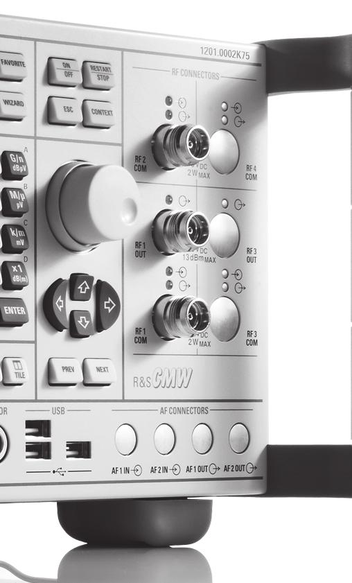
25 General data RF connectors (front panel) RF1 OUT Snap-N female, 50 Ω, compatible with N female connectors combined RF input and RF output RF output Remote control interfaces (front panel) LAN Ethernet RJ-45 connector, 100 Mbps Remote control interfaces (rear panel) IEEE 488 LAN REMOTE USB REMOTE R&S CMW-B612A IEEE bus (single) interface option or R&S CMW-B612B IEEE bus (dual) interface option IEC (IEEE 488.2), 24-pin Amphenol connector 2 IEC (IEEE 488.2), 24-pin Amphenol connector Ethernet RJ-45 connector, 1000 Mbps USB 2.0 type B connector Further interfaces (front panel) USB for keyboard, mouse, USB stick 3 USB 2.0 type A connector SENSOR for R&S NRP-Zxx power sensors DIGITAL MONITOR for external monitor, only included in R&S CMW-S600C DVI-D connector Further interfaces (rear panel) USB DVI TRIG A, TRIG B for keyboard, mouse, USB stick for external monitor, R&S CMW-B620A DVI interface option trigger input/output output trigger sources 1 USB 2.0 type A connector 1 USB 1.1 type A connector DVI-D connector 2 BNC connector standard-specific internal trigger sources Environmental conditions Temperature operating temperature range +5 C to +45 C storage temperature range 25 C to +60 C Relative humidity +40 C, non-condensing 80 % Product conformity Electromagnetic compatibility EU: EMC Directive 2004/108/EC in line with EN (industrial environment) EN EN (class A) EN EN Electrical safety EU: Low Voltage Directive 2006/95/EC in line with EN USA/Canada in line with UL (second edition) CAN C22.2 No Rohde & Schwarz R&S CMW270 Wireless Connectivity Tester 25
26 Mechanical resistance non-operating mode Vibration sinusoidal in line with EN , 5 Hz to 150 Hz, 0.15 mm amplitude const., 55 Hz to 150 Hz, 0.5 g const. Vibration random in line with EN , 10 Hz to 300 Hz, acceleration 1.2 g RMS Shock in line with MIL-STD-810F 40 g shock spectrum Power supply power factor correction, in line with EN Input 100 V to 240 V ± 10 % (AC), max. 850 VA, 50 Hz to 60 Hz ± 5 % Power consumption R&S CMW270 single tester, non-signaling approx. 200 W Display selected with R&S CMW-S600D (front panel with display and keypad) Size 21 cm TFT color display (8.4") Resolution pixels (SVGA resolution) Pixel failure rate < Dimensions of the R&S CMW270 Weight of the R&S CMW270 W H D, overall mm mm mm (18.31 in 7.77 in in) for rackmounting 19" 1/1, 4 HU, 450 single tester, non-signaling approx. 14 kg (approx. 31 lb) with typical options approx. 18 kg (approx. 40 lb) Calibration interval 12 months recommended for highest accuracy, see specified RF generator and RF analyzer level uncertainty 24 months add 0.2 db to specified RF generator and RF analyzer level uncertainty 26 Rohde & Schwarz R&S CMW270 Wireless Connectivity Tester
27 Ordering information Designation Type Order No. Wireless Connectivity Tester Base unit with following accessories: power cord, operating manual (quick start guide), comprehensive documentation on CD-ROM R&S CMW K75 For more ordering information about available options, please see our product brochure (PD ) or ask your local Rohde & Schwarz expert to find the solution that is optimally suited to your needs. Recommended extras for manual operation For R&S CMW-S600D configuration (front panel with display and keypad): Designation Type Order No. Mouse with USB Interface, optical R&S PSL-Z For R&S CMW-S600C configuration (front panel without display or keypad): Designation Type Order No. Mouse with USB Interface, optical R&S PSL-Z Keyboard with USB Interface (US assignment) R&S PSL-Z " TFT Monitor R&S PMC Important information: We recommend using only the above-mentioned original PC components from Rohde & Schwarz in connection with the R&S CMW270. The interaction of all components is continuously tested. Insufficiently shielded PC components may lead to EMC problems which may disturb RF measurements results. Recommended extras Designation Type Order No. 19" Rack Adapter R&S ZZA Digital Signal Interface Module R&S EX-IQ-BOX K04 Cable TVR 290, 26-pin MDR connector; additional cable for R&S CMW-B510A used with e.g. R&S AMU200A, R&S EX-IQ-BOX R&S SMU-Z For product brochure, see PD and Rohde & Schwarz R&S CMW270 Wireless Connectivity Tester 27
28 Service you can rely on J Worldwide J Local and personalized J Customized and flexible J Uncompromising quality J Long-term dependability About Rohde & Schwarz Rohde & Schwarz is an independent group of companies specializing in electronics. It is a leading supplier of solutions in the fields of test and measurement, broadcasting, radiomonitoring and radiolocation, as well as secure communications. Established more than 75 years ago, Rohde & Schwarz has a global presence and a dedicated service network in over 70 countries. Company headquarters are in Munich, Germany. Environmental commitment Energy-efficient products Continuous improvement in environmental sustainability ISO certified environmental management system Certified Quality System ISO 9001 Rohde & Schwarz GmbH & Co. KG Regional contact Europe, Africa, Middle East customersupport@rohde-schwarz.com North America TEST RSA ( ) customer.support@rsa.rohde-schwarz.com Latin America customersupport.la@rohde-schwarz.com Asia/Pacific customersupport.asia@rohde-schwarz.com R&S is a registered trademark of Rohde & Schwarz GmbH & Co. KG Trade names are trademarks of the owners Printed in Germany (ch) PD Version April 2010 R&S CMW270 Subject to change Rohde & Schwarz GmbH Co. KG München, Germany
Bluetooth Tester CBT. Specifications. Specifications. Version January 2006
 Specifications Version 03.00 Bluetooth Tester CBT January 2006 Specifications CONTENTS UNIT SPECIFICATIONS...3 TIMEBASE TCXO...3 REFERENCE FREQUENCY INPUT...3 RF GENERATOR...3 RF ANALYZER...5 Power meter
R&S FSV-K8 Bluetooth /EDR Measurement Application Specifications
 R&S FSV-K8 Bluetooth /EDR Measurement Application Specifications Test & Measurement Data Sheet 01.01 CONTENTS R&S FSV-K8 Bluetooth /EDR measurement application... 3 Frequency...3 Measurement parameters...3
R&S FSQ-K91/K91n/K91ac WLAN a/b/g/j/n/ac Application Firmware Specifications
 R&S FSQ-K91/K91n/K91ac WLAN 802.11a/b/g/j/n/ac Application Firmware Specifications Test & Measurement Data Sheet 03.00 CONTENTS OFDM analysis (IEEE 802.11a, IEEE 802.11g OFDM, IEEE 802.11j, )... 3 Frequency...3
R&S FSV-K73 3G FDD UE (UL) Measurements incl. HSUPA Specifications
 Measurements incl. HSUPA Specifications") FSV-K73_dat-sw_en_5214-0976-22_cover.indd 1 Data Sheet 02.00 Test & Measurement R&S FSV-K73 3G FDD UE (UL) Measurements incl. HSUPA Specifications 01.08.2013 17:36:27 CONTENTS Specifications... 3 Frequency...
FSV-K73_dat-sw_en_5214-0976-22_cover.indd 1 Data Sheet 02.00 Test & Measurement R&S FSV-K73 3G FDD UE (UL) Measurements incl. HSUPA Specifications 01.08.2013 17:36:27 CONTENTS Specifications... 3 Frequency...
R&S FSV-K76 TD-SCDMA BS (DL) Measurements Specifications
 Measurements Specifications") FSV_K76_dat-sw_en_5214-1572-22_cover.indd 1 Data Sheet 02.00 Test & Measurement R&S FSV-K76 TD-SCDMA BS (DL) Measurements Specifications 07.08.2013 18:42:49 CONTENTS Specifications... 3 Frequency... 3
FSV_K76_dat-sw_en_5214-1572-22_cover.indd 1 Data Sheet 02.00 Test & Measurement R&S FSV-K76 TD-SCDMA BS (DL) Measurements Specifications 07.08.2013 18:42:49 CONTENTS Specifications... 3 Frequency... 3
R&S FSW-K76/-K77 3GPP TD-SCDMA BS/UE Measurement Applications Specifications
 R&S FSW-K76/-K77 3GPP TD-SCDMA BS/UE Measurement Applications Specifications Test & Measurement Data Sheet 01.00 CONTENTS Definitions... 3 Specifications... 4 Frequency... 4 Level... 4 Signal acquisition...
WLAN IEEE802.11a/b/g/j/p/n/ac/ax Measurement Application Specifications
 WLAN IEEE802.11a/b/g/j/p/n/ac/ax Measurement Application Specifications R&S VSE-K91x R&S FSW-K91x R&S FPS-K91x Data Sheet Version 02.00 CONTENTS Definitions... 3 Specifications... 4 General remarks...
R&S SMBV-Z1 Reference Frequency Converter Specifications
 Test & Measurement Data Sheet 01.01 R&S SMBV-Z1 Reference Frequency Converter Specifications Version 01.01, July 2011 CONTENTS Definitions... 3 Introduction... 4 Specifications... 4 Input signal...4 Output
R&S HF907DC SHF Downconverter Specifications
 Radiomonitoring & Radiolocation Data Sheet 01.03 R&S HF907DC SHF Downconverter Specifications CONTENTS Definitions... 3 Specifications... 4 Frequency conversion... 4 Input and output properties... 4 Rechargeable
EX-IQ-Box Digital Signal Interface Module Specifications
 Test & Measurement Data Sheet 01.01 EX-IQ-Box Digital Signal Interface Module Specifications Introduction The R&S EX-IQ-Box is a digital interface module that provides flexible digital baseband inputs
R&S ZN-Z154 Calibration Unit Specifications
 ZN-Z154_dat-sw_en_3607-0481-22_v0101_cover.indd 1 Data Sheet 01.01 Test & Measurement R&S ZN-Z154 Calibration Unit Specifications 25.06.2014 10:27:09 CONTENTS Definitions... 3 Measurement range... 4 Effective
R&S TS-BCAST DVB-H IP Packet Inserter Compact DVB H signal generator with integrated IP packet inserter
 Test & Measurement Product Brochure 02.00 R&S TS-BCAST DVB-H IP Packet Inserter Compact DVB H signal generator with integrated IP packet inserter R&S TS-BCAST DVB-H IP packet Inserter At a glance The R&S
R&S ZVA110 Vector Network Analyzer Specifications
 ZVA110_dat-sw_en_5214-4813-22_cover.indd 1 Data Sheet 04.00 Test & Measurement R&S ZVA110 Vector Network Analyzer Specifications 15.11.2013 14:42:28 CONTENTS Definitions... 3 Specifications... 4 Overview...
R&S ZV-Z81 Multiport Test Set, models.05/.09/.29 Specifications
 ZV-Z81_models5_9_29_dat-sw_en_5213-6864-22_Cover.indd 1 Data Sheet 04.01 Test & Measurement R&S ZV-Z81 Multiport Test Set, models.05/.09/.29 Specifications 17.04.2013 12:47:27 CONTENTS Definitions... 3
R&S FPC1000 Spectrum Analyzer Specifications
 R&S FPC1000 Spectrum Analyzer Specifications year Data Sheet Version 01.00 CONTENTS Definitions... 3 Specifications... 4 Frequency... 4 Sweep time... 4 Bandwidth... 4 Level... 5 Trigger functions... 6
EUTRA/LTE Downlink Specifications
 Test & Measurement Data Sheet 03.00 EUTRA/LTE Downlink Specifications R&S FS-K100PC/-K102PC/-K104PC R&S FSV-K100/-K102/-K104 R&S FSQ-K100/-K102/-K104 R&S FSW-K100/-K102/-K104 CONTENTS Definitions... 3
R&S ETH Handheld TV Analyzer Portable DVB-T/H signal analysis up to 3.6/8 GHz
 R&S ETH Handheld TV Analyzer Portable DVB-T/H signal analysis up to 3.6/8 GHz Broadcast Product Brochure 02.00 R&S ETH Handheld TV Analyzer At a glance The R&S ETH handheld TV analyzer was specially designed
R&S RSC Step Attenuator Where precise signal levels count
 Test & Measurement Product Brochure 01.00 Step Attenuator Where precise signal levels count Step Attenuator At a glance The is a switchable, mechanical step attenuator. It is available in various models
R&S ZN-Z85 Switch Matrix Specifications
 R&S ZN-Z85 Switch Matrix Specifications Data Sheet Version 01.02 CONTENTS Definitions... 3 Block diagrams... 4 Specifications... 5 General features... 5 Performance data... 5 Remote control... 5 Switching
R&S ZN-Z103 Calibration Unit Specifications. Data Sheet V02.01
 R&S ZN-Z103 Calibration Unit Specifications Data Sheet V02.01 CONTENTS Definitions... 3 Measurement range... 5 Effective system data... 5 General data... 6 Ordering information... 7 2 Rohde & Schwarz R&S
R&S ZVA-Zxx Millimeter-Wave Converters Specifications
 ZVA-Zxx_dat-sw_en_5214.2033.22_umschlag.indd 1 Data Sheet 13.00 Test & Measurement R&S ZVA-Zxx Millimeter-Wave Converters Specifications 28.01.2013 15:08:06 CONTENTS General information... 3 Definitions...
R&S FSV-K40 Phase Noise Measurement Application Specifications
 FSV-K40_dat-sw_en_5213-9705-22_cover.indd 1 Data Sheet 02.00 Test & Measurement R&S FSV-K40 Phase Noise Measurement Application Specifications 06.10.2014 14:51:49 CONTENTS Specifications... 3 Ordering
R&S FSW-B512R Real-Time Spectrum Analyzer 512 MHz Specifications
 R&S FSW-B512R Real-Time Spectrum Analyzer 512 MHz Specifications Data Sheet Version 02.00 CONTENTS Definitions... 3 Specifications... 4 Level... 5 Result display... 6 Trigger... 7 Ordering information...
R&S FPS-K18 Amplifier Measurements Specifications
 R&S FPS-K18 Amplifier Measurements Specifications Data Sheet Version 02.00 Specifications The specifications of the R&S FPS-K18 amplifier measurements are based on the data sheet of the R&S FPS signal
R&S RT-Zxx High-Bandwidth Probes Specifications
 R&S RT-Zxx High-Bandwidth Probes Specifications Test & Measurement Data Sheet 14.00 CONTENTS Definitions... 3 Probe/oscilloscope chart... 4 R&S RT-ZZ80 transmission line probe... 5 R&S RT-ZS10/-ZS10E/-ZS20/-ZS30
R&S ADMC8 Multicoupler Active UHF multicoupler for 8-port ATC signal distribution
 Secure Communications Product Brochure 01.00 R&S ADMC8 Multicoupler Active UHF multicoupler for 8-port ATC signal distribution R&S ADMC8 Multicoupler At a glance The R&S ADMC8 is a multicoupler specifically
Test and Communications Antennas for the R&S TS8991 OTA Performance Test System Specifications
 Test and Communications Antennas for the R&S TS8991 OTA Performance Test System Specifications R&S TC-TA18 cross-polarized Vivaldi test antenna, R&S TC-CA6 linear-polarized communications antenna Data
R&S FSW-K160RE 160 MHz Real-Time Measurement Application Specifications
 FSW-K160RE_dat-sw_en_3607-1759-22_v0200_cover.indd 1 Data Sheet 02.00 Test & Measurement R&S FSW-K160RE 160 MHz Real-Time Measurement Application Specifications 06.04.2016 17:16:27 CONTENTS Definitions...
R&S FSW-K144 5G NR Measurement Application Specifications
 R&S FSW-K144 5G NR Measurement Application Specifications Data Sheet Version 01.00 CONTENTS Definitions... 3 Specifications... 4 Overview... 4 Assignment of option numbers to link modes... 4 Supported
R&S AVG050 DVB Satellite Receiver Specifications
 AVG050-SAT_dat-sw_en_3606-8508-22_v0400_cover.indd 1 Data Sheet 04.00 Broadcast and Media R&S AVG050 DVB Satellite Receiver Specifications 14.11.2014 14:40:08 CONTENTS Definitions... 3 Specifications...
R&S ZND Vector Network Analyzer Specifications
 R&S ZND Vector Network Analyzer Specifications year Test & Measurement Data Sheet 02.01 CONTENTS Definitions... 3 Measurement range... 4 Measurement speed... 5 Measurement accuracy... 7 Effective system
Product Brochure Version R&S RSC Step Attenuator Where precise signal levels count
 Product Brochure Version 02.00 Step Attenuator Where precise signal levels count RSC_bro_en_5214-4413-12_v0200.indd 1 07.09.2018 10:36:40 Step Attenuator At a glance The is a switchable, mechanical step
R&S GU221 Filter Control Unit Specifications
 R&S GU221 Filter Control Unit Specifications Secure Communications Data Sheet 01.00 Definitions General Product data applies under the following conditions: Three hours storage at ambient temperature followed
EUTRA/LTE Measurement Application Specifications
 EUTRA/LTE Measurement Application Specifications R&S VSE-K10x R&S FSx-K10x R&S FS-K10xPC Test & Measurement Data Sheet 02.00 CONTENTS Definitions... 3 Specifications... 4 General remarks... 4 Overview...
R&S SGS100A SGMA RF Source Specifications
 R&S SGS100A SGMA RF Source Specifications Test & Measurement Data Sheet 04.00 CONTENTS Key features... 3 Definitions... 4 RF performance... 5 Frequency... 5 Reference frequency... 5 Level... 6 Spectral
Test and Communications Antennas for the R&S TS8991 OTA Performance Test System Specifications
 Test and Communications Antennas for the R&S TS8991 OTA Performance Test System Specifications R&S TC-TA18 cross-polarized Vivaldi test antenna, R&S TC-TA85CP cross-polarized Vivaldi test antenna, R&S
R&S EDS300 DME/Pulse Analyzer Specifications
 R&S EDS300 DME/Pulse Analyzer Specifications year Data Sheet Version 04.01 CONTENTS Definitions... 3 Specifications... 4 Frequency... 4 Level... 4 DME signal analysis... 4 TACAN signal analysis (R&S EDS-K1
R&S ZN-Z151/-Z152/-Z153 Calibration Unit Specifications
 ZN-Z151_152_153_dat-sw_en_3607-0881-22_v0100_cover.indd 1 Data Sheet 01.00 Test & Measurement R&S ZN-Z151/-Z152/-Z153 Calibration Unit Specifications 07.10.2014 11:35:47 CONTENTS Definitions... 3 Measurement
R&S HA-Z24E External Preamplifier 1 GHz to 85 GHz Specifications
 R&S HA-Z24E External Preamplifier 1 GHz to 85 GHz Specifications Data Sheet Version 01.01 Definitions General Product data applies under the following conditions: Three hours storage at ambient temperature
R&S SFD DOCSIS Signal Generator Signal generator for DOCSIS 3.1 downstream and upstream
 R&S SFD DOCSIS Signal Generator Signal generator for DOCSIS 3.1 downstream and upstream SFD_bro_en_3607-3739-12_v0100.indd 1 Product Brochure 01.00 Test & Measurement Broadcast & Media year 24.05.2016
R&S ZVA-Zxx Millimeter-Wave Converters Specifications
 R&S ZVA-Zxx Millimeter-Wave Converters Specifications Data Sheet Version 19.00 CONTENTS Definitions... 3 General information... 4 Specifications... 5 Test port... 5 Source input (RF IN)... 5 Local oscillator
R&S SGU100A SGMA Upconverter Specifications
 R&S SGU100A SGMA Upconverter Specifications Test & Measurement Data Sheet 03.00 CONTENTS Key features... 3 Definitions... 4 Specifications... 5 RF performance... 5 Frequency... 5 Level... 5 Spectral purity...
EUTRA/LTE and LTE-Advanced Signal Analysis Transmitter measurements on LTE signals
 EUTRA/LTE and LTE-Advanced Signal Analysis Transmitter measurements on LTE signals R&S FS-K100PC/-K101PC/-K102PC/-K103PC/-K104PC/-K105PC Test & Measurement Product Brochure 03.00 EUTRA/LTE and LTE-Advanced
Product Brochure Version R&S TSML-CW Radio Network Analyzer Powerful scanner for CW applications
 Product Brochure Version 02.01 Radio Network Analyzer Powerful scanner for CW applications TSML-CW_bro_en_5214-3246-12_v0200.indd 1 22.08.2017 11:50:23 Radio Network Analyzer At a glance The is the ideal
R&S ZN-ZTW Torque Wrench Specifications
 R&S ZN-ZTW Torque Wrench Specifications Test & Measurement Data Sheet 02.00 CONTENTS Definitions... 3 Specifications... 4 Mechanical specifications... 4 General data... 4 Dimensions (in mm)... 5 Ordering
R&S EDST300 TACAN/DME Station Tester Specifications
 R&S EDST300 TACAN/DME Station Tester Specifications year Data Sheet Version 01.01 CONTENTS Definitions... 3 Specifications... 4 Standards... 4 Frequency... 4 TX Power Measurement (R&S EDST300 analyzer)...
R&S DST200 RF Diagnostic Chamber Specifications
 DST200_dat-sw_en_5214-3600-22_v0500_cover.indd 1 Data Sheet 05.00 Test & Measurement R&S DST200 RF Diagnostic Chamber Specifications 08.04.2016 15:35:59 CONTENTS Definitions... 3 Base unit... 4 R&S DST200
R&S RT-Zxx High-Voltage and Current Probes Specifications
 R&S RT-Zxx High-Voltage and Current Probes Specifications Test & Measurement Data Sheet 14.00 CONTENTS Definitions... 3 Probe/oscilloscope chart... 4 R&S RT-ZH10/-ZH11 high-voltage probes... 5 R&S RT-ZD01
R&S FS-Z60/75/90/110 Harmonic Mixers for the R&S FSP/FSU/ FSQ/FSUP/FSV
 Test & Measurement Data Sheet 04.00 R&S FS-Z60/75/90/110 Harmonic Mixers for the R&S FSP/FSU/ FSQ/FSUP/FSV R&S FS-Z60/75/ 90/110 Harmonic Mixers At a glance The R&S FS-Z60/-Z75/-Z90/-Z110 harmonic mixers
R&S DDF200M Digital Direction Finder Specifications
 R&S DDF200M Digital Direction Finder Specifications Data Sheet Version 02.00 CONTENTS Definitions... 3 Specifications... 4 Frequency... 4 Direction finding... 4 Linearity... 4 Interference rejection...
R&S TS-ISC In-System Calibration Kit On-site calibration solution for R&S CompactTSVP
 TS-ISC_bro_en_5214-1972-12.indd 1 Product Brochure 02.00 Test & Measurement R&S TS-ISC In-System Calibration Kit On-site calibration solution for R&S CompactTSVP 24.09.2013 10:08:56 R&S TS-ISC In-System
R&S ZNBT Vector Network Analyzer Specifications
 R&S ZNBT Vector Network Analyzer Specifications year Data Sheet Version 05.02 CONTENTS Definitions... 3 Measurement range... 4 Measurement speed... 6 Measurement accuracy of the R&S ZNBT8... 8 Measurement
R&S TS-PMB Switch Matrix Module High-density, 90-channel, full matrix relay multiplexer module
 TS-PMB_bro_en_0758-0600-12.indd 1 Product Brochure 02.00 Test & Measurement Switch Matrix Module High-density, 90-channel, full matrix relay multiplexer module Switch Matrix Module At a glance Typical
Spectrum Analyzer 1.6 GHz 3 GHz R&S HMS-X
 HMS-X_bro_de-en_3607-0181-3X_v0200.indd 1 Product Brochure 02.00 Test & Measurement Spectrum Analyzer 1.6 GHz 3 GHz R&S HMS-X 15.03.2016 15:24:06 1 Basic Unit + 3 Options Key facts Frequency range: 100
R&S FSW-K54 EMI Measurement Application Detecting and eliminating electromagnetic
 R&S FSW-K54 EMI Measurement Application Detecting and eliminating electromagnetic interference Test & Measurement Product Brochure 01.00 R&S FSW-K54 EMI Measurement Application At a glance The R&S FSW-K54
Product Brochure Version HZ-15_16_17_bro_en_ _v0100.indd 1
 Product Brochure Version 1. R&S HZ-15/R&S HZ-17 Probe Sets R&S HZ-16 Preamplifier E and H near-field emission measurements with test receivers, spectrum analyzers and oscilloscopes HZ-15_16_17_bro_en_5213-6687-12_v1.indd
R&S SGMA Product Family Compact fast reliable
 Test & Measurement Product Brochure 5. R&S SGMA Product Family Compact fast reliable R&S SGS1A SGMA RF Source, R&S SGU1A SGMA Upconverter R&S SGMA Product Family At a glance The R&S SGS1A is an RF source
Product Brochure Version R&S ENV A Four-Line V-Network RFI voltage measurements at high currents
 Product Brochure Version 01.00 200 A Four-Line V-Network RFI voltage measurements at high currents ENV4200_bro_en_5214-8390-12_v0100.indd 1 26.01.2017 15:22:54 200 A Four-Line V-Network At a glance The
R&S M3TR R&S VT3050C 50 W VHF/UHF Compact Power Amplifier Specifications
 Secure Communications Data Sheet 01.00 R&S M3TR R&S VT3050C 50 W VHF/UHF Compact Power Amplifier Specifications CONTENTS Specifications... 3 General data...3 RF data...4 Protection...4 Mechanical data...4
R&S TS-PFG Function Generator Module Dual-channel arbitrary waveform generator with isolated outputs
 TS-PFG_bro_en_0758-0639-12_v0300.indd 1 Product Brochure 03.00 Test & Measurement R&S TS-PFG Function Generator Module Dual-channel arbitrary waveform generator with isolated outputs 28.09.2016 16:05:56
DVG MPEG-2 Measurement Generator
 Data sheet Version 04.00 DVG MPEG-2 Measurement Generator October 2006 Digital TV test signals at a keystroke The DVG is a universal generator for digital TV signals. It generates in an endless loop a
R&S FK2900M HF Antenna Tuning Unit For stationary and shipboard applications
 Secure Communications Product Brochure 05.00 R&S FK2900M HF Antenna Tuning Unit For stationary and shipboard applications R&S FK2900M HF Antenna Tuning Unit At a glance The R&S FK2900M is an antenna tuning
Model 7330 Signal Source Analyzer Dedicated Phase Noise Test System V1.02
 Model 7330 Signal Source Analyzer Dedicated Phase Noise Test System V1.02 A fully integrated high-performance cross-correlation signal source analyzer from 5 MHz to 33+ GHz Key Features Complete broadband
R&S TSMx Radio Network Analyzers Powerful scanner family for mobile applications
 Test & Measurement Data Sheet 01.00 R&S TSMx Radio Network Analyzers Powerful scanner family for mobile applications R&S TSMx Radio Network Analyzers At a glance The R&S TSML, R&S TSMU and R&S TSMQ form
R&S FSMR Measuring Receiver Specifications
 Test & Measurement Data Sheet 09.00 R&S FSMR Measuring Receiver Specifications CONTENTS Specifications... 3 Frequency...3 Measuring receiver... 3 Frequency counter...3 RF power...4 RF level (tuned receiver)...5
R&S SLx8000 Family of UHF/VHF Transmitters Efficient solutions for analog and digital broadcasting standards
 Broadcasting Data Sheet 02.01 R&S SLx8000 Family of UHF/VHF Transmitters Efficient solutions for analog and digital broadcasting standards R&S SLx8000 Family of UHF/VHF Transmitters At a glance The UHF/VHF
R&S Cable Rider ZPH Cable and Antenna Analyzer Specifications
 R&S Cable Rider ZPH Cable and Antenna Analyzer Specifications year Data Sheet Version 02.02 CONTENTS Definitions... 3 Specifications... 4 Frequency... 4 Measurements... 4 Channel power meter (R&S ZPH-K19
R&S Spectrum Rider FPH Handheld spectrum analyzer
 R&S Spectrum Rider FPH Handheld spectrum analyzer PD 3607.2149.32 V 01.00 Small form factor to handle big tasks SpectrumRider_fly_en_3607_2149_32_v0100.indd 3 R&S Spectrum Rider FPH Modern and rugged portable
R&S PSL3 Industrial Controller The powerful industrial controller
 R&S PSL3 Industrial Controller The powerful industrial controller Test & Measurement Product Brochure 02.00 R&S PSL3 Industrial Controller At a glance Controllers play a major role in complex measurement
Application Note DT-AN-2115B-1. DTA-2115B Verification of Specifations
 DTA-2115B Verification of Specifations APPLICATION NOTE January 2018 Table of Contents 1. Introduction... 3 General Description of the DTA-2115B... 3 Purpose of this Application Note... 3 2. Measurements...
7000 Series Signal Source Analyzer & Dedicated Phase Noise Test System
 7000 Series Signal Source Analyzer & Dedicated Phase Noise Test System A fully integrated high-performance cross-correlation signal source analyzer with platforms from 5MHz to 7GHz, 26GHz, and 40GHz Key
Dynamic re-referencing Microvolt-level measurements with the R&S RTO oscilloscopes
 RTO_app-bro_3607-2855-92_v0100.indd 1 Microvolt-level measurements with the R&S RTO Test & Measurement Application Brochure 01.00 Dynamic re-referencing Microvolt-level measurements with the R&S RTO oscilloscopes
Application Note DT-AN DTU-315 Verification of Specifications
 DTU-315 Verification of Specifications APPLICATION NOTE January 2018 Table of Contents 1. Introduction... 3 General Description of the DTU-315... 3 Purpose of this Application Note... 3 2. Measurements...
R&S FPL1000 Spectrum Analyzer Specifications
 R&S FPL1000 Spectrum Analyzer Specifications year Data Sheet Version 02.00 CONTENTS Definitions... 3 Specifications... 4 Frequency... 4 Sweep time... 5 Resolution bandwidths... 5 Level... 6 Measurement
R&S VSE Vector Signal Explorer Base Software Specifications
 Data Sheet Version 10.00 R&S VSE Vector Signal Explorer Base Software Specifications VSE_dat-sw_en_3607-1371-22_v1000_cover.indd 1 26.04.2018 10:05:34 CONTENTS Definitions... 3 Specifications... 4 Minimum
R&S RT-Zxx Standard Probes Specifications
 R&S RT-Zxx Standard Probes Specifications Test & Measurement Data Sheet 16.00 CONTENTS Definitions... 3 Probe/oscilloscope chart... 4 R&S RT-ZP03 passive probe... 5 R&S RT-ZP05(S) passive probe... 8 R&S
R&S UMS12-OEM Monitoring System Modular monitoring system with open programming interface
 R&S UMS12 Monitoring System Modular monitoring system with open programming interface Radiomonitoring & Radiolocation Data Sheet 01.00 R&S UMS12 Monitoring System At a glance The R&S UMS12 is a new member
R&S Cable Rider ZPH Cable and Antenna Analyzer Specifications
 R&S Cable Rider ZPH Cable and Antenna Analyzer Specifications year Data Sheet Version 01.01 CONTENTS Definitions... 3 Specifications of the R&S Cable Rider ZPH Cable and Antenna Analyzer... 4 Frequency...
R&S EFL110/EFL210 Cable TV Analyzer and Leakage Detector Detecting interference in cable TV and LTE networks
 R&S EFL110/EFL210 Cable TV Analyzer and Leakage Detector Detecting interference in cable TV and LTE networks Broadcasting Product Brochure 02.00 R&S EFL110/ R&S EFL210 Cable TV Analyzer and Leakage Detector
R&S SFC Compact Modulator and R&S SFC-U Compact USB Modulator Test signals for TV and audio broadcasting handy and economical
 Broadcasting Product Brochure 02.00 R&S SFC Compact Modulator and R&S SFC-U Compact USB Modulator Test signals for TV and audio broadcasting handy and economical R&S SFC Compact Modulator and R&S SFC-U
R&S SMF100A Microwave Signal Generator Specifications
 R&S SMF100A Microwave Signal Generator Specifications Test & Measurement Data Sheet 04.00 Specifications Specifications apply under the following conditions: 30 minutes warm-up time at ambient temperature,
R&S CMU200 Universal Radio Communication Tester Specifications
 R&S CMU200 Universal Radio Communication Tester Specifications Test & Measurement Data Sheet 09.00 CONTENTS Base unit specifications... 5 Timebase TCXO...5 Timebase OCXO R&S CMU-B11 option...5 Timebase
R&S VSE Vector Signal Explorer Base Software Specifications
 R&S VSE Vector Signal Explorer Base Software Specifications Data Sheet Version 11.00 CONTENTS Definitions... 3 Specifications... 4 Minimum system requirements for the R&S VSE... 4 Running on a PC... 4
ESU EMI Test Receiver Specifications
 ESU EMI Test Receiver Specifications Test & Measurement Data Sheet 02.01 CONTE NT S BASE UNIT... 3 FREQUENCY... 3 RECEIVER SCAN... 4 SWEEP... 4 PRESELECTION... 4 IF AND RESOLUTION BANDWIDTHS... 5 LEVEL...
Pre-5G-NR Signal Generation and Analysis Application Note
 Pre-5G-NR Signal Generation and Analysis Application Note Products: R&S SMW200A R&S VSE R&S SMW-K114 R&S VSE-K96 R&S FSW R&S FSVA R&S FPS This application note shows how to use Rohde & Schwarz signal generators
R&S FSMR Measuring Receiver All-in-one calibration of signal generators and attenuators
 R&S FSMR Measuring Receiver All-in-one calibration of signal generators and attenuators Product Brochure Version 04.00 year FSMR_Bro_en_0758-2319-12_v0400.indd 1 19.05.2017 14:41:56 R&S FSMR Measuring
R&S EFL240/R&S EFL340 Portable TV Test Receiver Professional installation of cable and satellite TV systems and antennas
 R&S EFL240/R&S EFL340 Portable TV Test Receiver Professional installation of cable and satellite TV systems and antennas Broadcasting Product Brochure 03.00 R&S EFL240/ R&S EFL340 Portable TV Test Receiver
R&S ZNL Vector Network Analyzer Specifications
 R&S ZNL Vector Network Analyzer Specifications year Data Sheet Version 01.00 CONTENTS Definitions... 3 Specifications... 4 Measurement range... 4 Measurement speed... 5 Measurement accuracy... 6 Effective
<EDGE Looped based BER and TX measurements using ARB files on the R&S CMW 500> Products: R&S CMW500 R&S CMW- KW200 R&S CMW- KM200. <Application Note>
 Application Note Products: R&S CMW500 R&S CMW- KW200 R&S CMW- KM200 -
MTP200B WLAN / BT LE Tester
 www.tescom.co.kr MTP200B WLAN / BT LE Tester Introduction Tescom s MTP200B is a non-signaling test-based WLAN or BT LE (Low Energy) tester. As one-body equipment incorporating both Signal Generator and
DOCSIS 3.1 Full channel loading Maximizing data throughput
 DOCSIS 3.1 Full channel loading Maximizing data throughput Test and measurement High-end solutions Turn your signals into success. Introduction With over 80 years of experience in the field of RF test
SMS3000X Series Spectrum Analyzer
 Data Sheet SMS3000X Series Spectrum Analyzer SMS3032X SMS3021X General Description SMS3000X series spectrum analyzer has a frequency range from 9 khz up to 2.1 GHz/3.2 GHz, it is light weight and small
Spectrum Analyzer 1.6 GHz 3 GHz HMS-X
 Spectrum Analyzer 1.6 GHz 3 GHz 1 Basic Unit + 3 Options Your Spectrum Analyzer Key facts Frequency range: 100 khz to 1.6 GHz/3 GHz* 1 Spectral purity greater than -100 dbc/hz (at 100 khz) SWEEP from 20
R&S TS-PIO4 Digital Functional Test Module 32-channel programmable digital I/O module
 TS-PIO4_bro_en_3607-3474-12_v0100.indd 1 Product Brochure 01.00 Test & Measurement R&S TS-PIO4 Digital Functional Test Module 32-channel programmable digital I/O module 07.07.2016 07:41:56 R&S TS-PIO4
R&S XLx8000 UHF/VHF Transposers Efficient solutions for analog and digital broadcasting standards
 Broadcasting Product Brochure 04.00 R&S XLx8000 UHF/VHF Transposers Efficient solutions for analog and digital broadcasting standards R&S XLx8000 UHF/VHF Transposers At a glance R&S XLx8000 UHF/VHF transposers
R&S FSW Signal and Spectrum Analyzer Specifications
 Established 1981 Advanced Test Equipment Rentals www.atecorp.com 800-404-ATEC (2832) R&S FSW Signal and Spectrum Analyzer Specifications Test & Measurement Data Sheet 05.01 CONTENTS Definitions... 3 Specifications...
R&S CONTEST ITS Test cases and applications
 CONTEST_ITS_Test_Cases_dat-sw_en_3607-0352-22_v0200_cover.indd 1 Data Sheet 02.00 Test & Measurement R&S CONTEST ITS Test cases and applications 31.05.2016 14:03:11 CONTENTS Definitions... 3 CONTEST basic
R&S TS-PSM3 High-Power Switching Module Automotive DUT supply and load switching up to 30 A
 TS-PSM3_bro_en_3606-7282-12_v0100.indd 1 Product Brochure 01.00 Test & Measurement High-Power Switching Module Automotive DUT supply and load switching up to 30 A 24.02.2014 09:42:38 High-Power Switching
Fast. Accurate. USB-capable. Power sensors from Rohde & Schwarz
 Fast. Accurate. USB-capable. Power sensors from Rohde & Schwarz Power_sensors_bro_en_3606-7147-32.indd 1 22.05.2014 14:08:59 Fast. Accurate. USB-capable. Power sensors from Rohde & Schwarz The most important
R&S SFD DOCSIS Signal Generator Specifications
 R&S SFD DOCSIS Signal Generator Specifications year Broadcast & Media Data Sheet 01.00 CONTENTS Definitions... 3 RF characteristics... 4 Frequency... 4 Level... 4 Downstream/upstream outputs... 4 Spectral