Network Video Recorder. Quick Start Guide UD.6L0202B1847A01
|
|
|
- Gwendoline Johnston
- 6 years ago
- Views:
Transcription

1 Network Video Recorder Quick Start Guide UD.6L0202B1847A01
2 TABLE OF CONTENTS NVR Installation... 5 Hard Disk Installation... 5 Front Panel Rear Panel Peripheral Connections Wiring of Alarm Input Wiring of Alarm Output Using of Alarm Connectors Controller Connection Specifications Specifications of DS-9600NI-ST Specifications of DS-9600NI-RT Specification of DS-9600NI-XT Specifications of DS-8600NI-ST Specification of DS-7700NI-ST Specification of DS-7700NI-SP Specifications of DS-7600NI-ST Specifications of DS-7600NI-SP HDD Storage Calculation Chart Accessing by Web Browser Logging In Live View Recording Playback Menu Operation Menu Structure Startup and Shutdown Changing Default Admin Password Live View Adding IP Cameras One-touch RAID Configuration Recording Instant Recording All-day Recording Playback Backup VCA Detection VCA Search
3 User Manual 2015 Hangzhou Hikvision Digital Technology Co., Ltd. This user manual is intended for users of NVR ( Product ). It includes instructions on how to use the Product. The software embodied in the Product is governed by the user license agreement covering that Product. About this Manual This Manual is subject to domestic and international copyright protection. Hangzhou Hikvision Digital Technology Co., Ltd. ( Hikvision ) reserves all rights to this manual. This manual cannot be reproduced, changed, translated, or distributed, partially or wholly, by any means, without the prior written permission of Hikvision. Trademarks and other Hikvision marks are the property of Hikvision and are registered trademarks or the subject of applications for the same by Hikvision and/or its affiliates. Other trademarks mentioned in this manual are the properties of their respective owners. No right of license is given to use such trademarks without express permission. Disclaimer TO THE MAXIMUM EXTENT PERMITTED BY APPLICABLE LAW, HIKVISION MAKES NO WARRANTIES, EXPRESS OR IMPLIED, INCLUDING WITHOUT LIMITATION THE IMPLIED WARRANTIES OF MERCHANTABILITY AND FITNESS FOR A PARTICULAR PURPOSE, REGARDING THIS MANUAL. HIKVISION DOES NOT WARRANT, GUARANTEE, OR MAKE ANY REPRESENTATIONS REGARDING THE USE OF THE MANUAL, OR THE CORRECTNESS, ACCURACY, OR RELIABILITY OF INFORMATION CONTAINED HEREIN. YOUR USE OF THIS MANUAL AND ANY RELIANCE ON THIS MANUAL SHALL BE WHOLLY AT YOUR OWN RISK AND RESPONSIBILITY. TO THE MAXIMUM EXTENT PERMITTED BY APPLICABLE LAW, IN NO EVENT WILL HIKVISION, ITS DIRECTORS, OFFICERS, EMPLOYEES, OR AGENTS BE LIABLE TO YOU FOR ANY SPECIAL, CONSEQUENTIAL, INCIDENTAL, OR INDIRECT DAMAGES, INCLUDING, AMONG OTHERS, DAMAGES FOR LOSS OF BUSINESS PROFITS, BUSINESS INTERRUPTION, SECURITY BREACHES, OR LOSS OF DATA OR DOCUMENTATION, IN CONNECTION WITH THE USE OF OR RELIANCE ON THIS MANUAL, EVEN IF HIKVISION HAS BEEN ADVISED OF THE POSSIBILITY OF SUCH DAMAGES. SOME JURISDICTIONS DO NOT ALLOW THE EXCLUSION OR LIMITATION OF LIABILITY OR CERTAIN DAMAGES, SO SOME OR ALL OF THE ABOVE EXCLUSIONS OR LIMITATIONS MAY NOT APPLY TO YOU. Privacy Notice Surveillance laws vary by jurisdiction. Check all relevant laws in your jurisdiction before using this product for surveillance purposes to ensure that your use of this product conforms. Support Should you have any questions, please do not hesitate to contact your local dealer. 2
4 Regulatory information FCC information FCC compliance: This equipment has been tested and found to comply with the limits for a digital device, pursuant to part 15 of the FCC Rules. These limits are designed to provide reasonable protection against harmful interference when the equipment is operated in a commercial environment. This equipment generates, uses, and can radiate radio frequency energy and, if not installed and used in accordance with the instruction manual, may cause harmful interference to radio communications. Operation of this equipment in a residential area is likely to cause harmful interference in which case the user will be required to correct the interference at his own expense. FCC conditions This device complies with part 15 of the FCC Rules. Operation is subject to the following two conditions: 1. This device may not cause harmful interference. 2. This device must accept any interference received, including interference that may cause undesired operation. EU Conformity Statement This product and - if applicable - the supplied accessories too are marked with "CE" and comply therefore with the applicable harmonized European standards listed under the Low Voltage Directive 2006/95/EC, the EMC Directive 2004/108/EC, the RoHS Directive 2011/65/EU. 2012/19/EU (WEEE directive): Products marked with this symbol cannot be disposed of as unsorted municipal waste in the European Union. For proper recycling, return this product to your local supplier upon the purchase of equivalent new equipment, or dispose of it at designated collection points. For more information see: /66/EC (battery directive): This product contains a battery that cannot be disposed of as unsorted municipal waste in the European Union. See the product documentation for specific battery information. The battery is marked with this symbol, which may include lettering to indicate cadmium (Cd), lead (Pb), or mercury (Hg). For proper recycling, return the battery to your supplier or to a designated collection point. For more information see: 3


5 Preventive and Cautionary Tips Before connecting and operating your device, please be advised of the following tips: Ensure unit is installed in a well-ventilated, dust-free environment. Unit is designed for indoor use only. Keep all liquids away from the device. Ensure environmental conditions meet factory specifications. Ensure unit is properly secured to a rack or shelf. Major shocks or jolts to the unit as a result of dropping it may cause damage to the sensitive electronics within the unit. Use the device in conjunction with an UPS if possible. Power down the unit before connecting and disconnecting accessories and peripherals. A factory recommended HDD should be used for this device. Improper use or replacement of the battery may result in hazard of explosion. Replace with the same or equivalent type only. Dispose of used batteries according to the instructions provided by the battery manufacturer. CHANGE THE DEFAULT PASSWORD The default password (12345) for the Admin account is for first-time log-in purposes only. You must change this default password to better protect against security risks, such as the unauthorized access by others to the product that may prevent the product from functioning functioning properly and/or lead to other undesirable consequences. For your privacy, we strongly recommend changing the password to something of your own choosing (using a minimum of 8 characters, including upper case letters, lower case letters, numbers, and special characters) in order to increase the security of your product. Proper configuration of all passwords and other security settings is the responsibility of the installer and/or end-user. 4
6 Thank you for purchasing our product. If there is any question or request, please do not hesitate to contact dealer. This manual is applicable to the models listed in the following table. Series Model Type 9600NI-ST 9600NI-RT 9600NI-XT 8600NI-ST 7700NI-ST 7700NI-SP 7600NI-ST 7600NI-SP NVR Installation During the installation of the NVR: DS-9608NI-ST DS-9616NI-ST DS-9632NI-ST DS-9664NI-ST DS-9608NI-RT DS-9616NI-RT DS-9632NI-RT DS-9664NI-RT DS-9616NI-XT DS-9632NI-XT DS-9664NI-XT DS-8608NI-ST DS-8616NI-ST DS-8632NI-ST DS-8664NI-ST DS-7708NI-ST DS-7716NI-ST DS-7732NI-ST DS-7764NI-ST DS-7708NI-SP DS-7716NI-SP DS-7732NI-SP DS-7608NI-ST DS-7616NI-ST DS-7632NI-ST DS-7608NI-SP DS-7616NI-SP DS-7632NI-SP Network Video Recorder Network Video Recorder Network Video Recorder Network Video Recorder Network Video Recorder Network Video Recorder Network Video Recorder Network Video Recorder 1. Use brackets for rack mounting. 2. Ensure there is ample room for audio and video cables. 3. When routing cables, ensure that the bend radius of the cables are no less than five times than its diameter. 4. Connect the alarm cable. 5. Allow at least 2cm ( 0.75-inch) of space between racks mounted devices. 6. Ensure the NVR is grounded. 7. Environmental temperature should be within the range of -10 ºC ~ 55 ºC, 14ºF ~ 131ºF. 8. Environmental humidity should be within the range of 10% ~ 90%. Hard Disk Installation Before you start: Disconnect the power from the NVR before installing a hard disk drive (HDD). A factory recommended HDD should be used for this installation. For DS-7600NI-ST&SP, up to 2 SATA hard disks can be installed; for DS-7700NI-ST&SP, up to 4 SATA hard 5

: 1.")


7 disks can be installed; for DS-9600NI-XT, up to 16 SATA hard disks can be installed, and up to 8 SATA hard disks can be installed for other models. Tools Required: Screwdriver. Steps (for DS-9600NI-ST/RT/XT): 1. Fasten the hard disk mounting handle to the hard disk with screws. 2. Insert the key and turn in clockwise direction to open the panel lock. 3. Press the buttons on the panel of two sides and open the front panel. 4. Insert the hard disk along the slot until it is placed into position. 6


8 5. Repeat the above steps to install other hard disks onto the NVR. After having finished the installation of all hard disks, close the front panel and lock it with the key again. Steps (for DS-8600NI-ST): 1. Remove the cover from the NVR by unfastening the screws on the back and side. 2. Install the HDD in the HDD rack using the provided screws. Fasten the screws on the button to fix the HDD. 3. Connect one end of the data cable to the motherboard of NVR and the other end to the HDD. 7


9 4. Connect the power cable to the HDD. 5. Re-install the cover of the NVR and fasten screws. Steps (for DS-7600NI-ST/SP and DS-7700NI-ST/SP): 1. Remove the cover from the NVR by unfastening the screws on the rear and side panel. 2. Connect one end of the data cable to the motherboard of NVR and the other end to the HDD. 3. Connect the power cable to the HDD. 8


10 4. Place the HDD on the bottom of the device and then fasten the screws on the bottom to fix the HDD. 9
11 Front Panel DS-9600NI-ST/RT DS-9600NI-XT DS-8600NI-ST No. Name Function Description ALARM Turns red when a sensor alarm is detected. READY Ready LED is normally blue, indicating that the device is functioning properly. Turns blue when device is controlled by an IR remote. 1 STATUS Turns red when controlled by a keyboard and purple when IR Status remote and keyboard is used at the same time. Indicators HDD Flashes red when data is being read from or written to HDD. MODEM (not for Reserved for future usage. DS-9600NI-XT) TX/RX Flashes blue when network connection is functioning properly. 10
12 No. Name Function Description Guard LED turns blue when the device is in armed status; at this time, an alarm is enabled when an event is detected. GUARD The LED turns off when the device is unarmed. The arm/disarm status can be changed by pressing and holding on the ESC button for more than 3 seconds in live view mode. 2 IR Receiver Receiver for IR remote 3 Front Panel Lock (for DS-9600NI-ST/RT/XT series) You can lock or unlock the panel by the key. 4 DVD-R/W Slot for DVD-R/W. 5 Alphanumeric Buttons Switch to the corresponding channel in Live view or PTZ Control mode. Input numbers and characters in Edit mode. Switch between different channels in Playback mode. The light of the button is blue when the corresponding channel is recording; it is red when the channel is in network transmission status; it is pink when the channel is recording and transmitting. 6 USB Interfaces Universal Serial Bus (USB) ports for additional devices such as USB mouse and USB Hard Disk Drive (HDD). ESC Back to the previous menu. Press for Arming/disarming the device in Live View mode. Enter the Manual Record setting menu. REC/SHOT In PTZ control settings, press the button and then you can call a PTZ preset by pressing Numeric button. It is also used to turn audio on/off in the Playback mode. PLAY/AUTO The button is used to enter the Playback mode. It is also used to auto scan in the PTZ Control menu. ZOOM+ Zoom in the PTZ camera in the PTZ Control setting. Adjust focus in the PTZ Control menu. A/FOCUS+ It is also used to switch between input methods (upper and lowercase alphabet, symbols and numeric input). Edit text fields. When editing text fields, it will also function as Composite 7 Keys EDIT/IRIS+ MAIN/SPOT/ZOO M- F1/ LIGHT F2/ AUX a Backspace button to delete the character in front of the cursor. On checkbox fields, pressing the button will tick the checkbox. In PTZ Control mode, the button adjusts the iris of the camera. In Playback mode, it can be used to generate video clips for backup. Enter/exit the folder of USB device and esata HDD. Switch between main and spot output. In PTZ Control mode, it can be used to zoom out the image. Select all items on the list when used in a list field. In PTZ Control mode, it will turn on/off PTZ light (if applicable). In Playback mode, it is used to switch between play and reverse play. Cycle through tab pages. In synchronous playback mode, it is used to switch between 11
13 No. Name Function Description channels. MENU/WIPER Press the button will help you return to the Main menu (after successful login). Press and hold the button for 5 seconds will turn off audible key beep. In PTZ Control mode, the MENU/WIPER button will start wiper (if applicable). In Playback mode, it is used to show/hide the control interface. PREV/FOCUS- Switch between single screen and multi-screen mode. In PTZ Control mode, it is used to adjust the focus in conjunction with the A/FOCUS+ button. PTZ/IRIS- Enter the PTZ Control mode. In the PTZ Control mode, it is used to adjust the iris of the PTZ camera. DIRECTION The DIRECTION buttons are used to navigate between different fields and items in menus. In the Playback mode, the Up and Down button is used to speed up and slow down recorded video. The Left and Right button will select the next and previous record files. In Live View mode, these buttons can be used to cycle through channels. 8 Control In PTZ control mode, it can control the movement of the PTZ Buttons camera. The ENTER button is used to confirm selection in any of the menu modes. It can also be used to tick checkbox fields. ENTER In Playback mode, it can be used to play or pause the video. In single-frame Playback mode, pressing the button will advance the video by a single frame. In Auto-switch mode, it can be used to stop /start auto switch. 9 JOG SHUTTLE Control Move the active selection in a menu. It will move the selection up and down. In Live View mode, it can be used to cycle through different channels. In the Playback mode: For DS-9600NI-ST/RT/XT series, the ring is used to jump 30s forward/backward in video files. For DS-8600NI-ST series, the outer ring is used to speed up or slow down the record files and the inner ring is used to jump 30s forward/backward in records files. In PTZ control mode, it can control the movement of the PTZ camera. 10 POWER ON/OFF Power on/off switch. 12
14 DS-7700NI-ST/SP No. Name Function Description POWER Turns green when NVR is powered up. READY The LED is green when the device is running normally. The light is green when the IR remote control is enabled; 1 Status Indicators STATUS The light is red when the function of the composite keys (SHIFT) are used; The light is out when none of the above condition is met. ALARM The light is red when there is an alarm occurring. HDD Blinks red when HDD is reading/writing. Tx/Rx Blinks green when network connection is functioning normally. 2 DVD-R/W Slot for DVD-R/W. In menu mode, the direction buttons are used to navigate between different fields and items and select setting parameters. In playback mode, the Up and Down buttons are used to speed up DIRECTION and slow down record playing, and the Left and Right buttons are used to move the recording 30s forwards or backwards. In the image setting interface, the up and down button can adjust 3 Control Buttons the level bar of the image parameters. In live view mode, these buttons can be used to switch channels. The Enter button is used to confirm selection in menu mode; or used to check checkbox fields and ON/OFF switch. In playback mode, it can be used to play or pause the video. ENTER In single-frame play mode, pressing the Enter button will play the video by a single frame. In auto sequence view mode, the buttons can be used to pause or resume auto sequence. Switch between the numeric or letter input and functions of the SHIFT composite keys. (Input letter or numbers when the light is out; Realize functions when the light is red.) 4 Composite Keys 1/MENU Enter numeral 1 ; Access the main menu interface. Enter numeral 2 ; 2/ABC/F1 Enter letters ABC ; The F1 button when used in a list field will select all items in the list. 13
15 No. Name Function Description In PTZ Control mode, it will turn on/off PTZ light and when the image is zoomed in, the key is used to zoom out. Enter numeral 3 ; Enter letters DEF ; 3/DEF/F2 The F2 button is used to change the tab pages. In PTZ control mode, it zooms in the image. Enter numeral 4 ; 4/GHI/ESC Enter letters GHI ; Exit and back to the previous menu. Enter numeral 5 ; Enter letters JKL ; 5/JKL/EDIT Delete characters before cursor; Check the checkbox and select the ON/OFF switch; Start/stop record clipping in playback. Enter numeral 6 ; 6/MNO/PLAY Enter letters MNO ; Playback, for direct access to playback interface. Enter numeral 7 ; 7/PQRS/REC Enter letters PQRS ; Open the manual record interface. 8/TUV/PTZ 9/WXYZ/PRE V 0/A 5 JOG SHUTTLE Control Enter numeral 8 ; Enter letters TUV ; Access PTZ control interface. Enter numeral 9 ; Enter letters WXYZ ; Multi-channel display in live view. Enter numeral 0 ; Shift the input methods in the editing text field. (Upper and lowercase, alphabet, symbols or numeric input). Double press the button to switch the main and auxiliary output. Move the active selection in a menu. It will move the selection up and down. In Live View mode, it can be used to cycle through different channels. In the Playback mode, it can be used to jump 30s forward/backward in video files. In PTZ control mode, it can control the movement of the PTZ camera. 6 POWER ON/OFF Power on/off switch. 7 USB Interfaces Universal Serial Bus (USB) ports for additional devices such as USB mouse and USB Hard Disk Drive (HDD). 14
16 DS-7600NI-ST/SP: No. Name Function Description 1 USB Interface Connects USB mouse or USB flash memory devices. POWER Turns green when NVR is powered up. READY The LED is green when the device is running normally. The light is green when the IR remote control is enabled; 2 Status STATUS The light is red when the function of the composite keys (SHIFT) are used; Indicators The light is out when none of the above condition is met. ALARM The light is red when there is an alarm occurring. HDD Blinks red when HDD is reading/writing. Tx/Rx Blinks green when network connection is functioning normally. 3 SHIFT Switch between the numeric or letter input and functions of the composite keys. (Input letter or numbers when the light is out; Realize functions when the light is red.) Switch between the numeric or letter input and functions of the SHIFT composite keys. (Input letter or numbers when the light is out; Realize functions when the light is red.) 1/MENU Enter numeral 1 ; Access the main menu interface. Enter numeral 2 ; Enter letters ABC ; 2/ABC/F1 The F1 button when used in a list field will select all items in the list. In PTZ Control mode, it will turn on/off PTZ light and when the image is zoomed in, the key is used to zoom out. Enter numeral 3 ; 4 Composite Enter letters DEF ; 3/DEF/F2 Keys The F2 button is used to change the tab pages. In PTZ control mode, it zooms in the image. Enter numeral 4 ; 4/GHI/ESC Enter letters GHI ; Exit and back to the previous menu. Enter numeral 5 ; Enter letters JKL ; 5/JKL/EDIT Delete characters before cursor; Check the checkbox and select the ON/OFF switch; Start/stop record clipping in playback. Enter numeral 6 ; 6/MNO/PLAY Enter letters MNO ; Playback, for direct access to playback interface. 15
17 No. Name Function Description 7/PQRS/REC Enter numeral 7 ; Enter letters PQRS ; Open the manual record interface. 8/TUV/PTZ Enter numeral 8 ; Enter letters TUV ; Access PTZ control interface. Enter numeral 9 ; 9/WXYZ/PRE Enter letters WXYZ ; V Multi-channel display in live view. Enter numeral 0 ; 0/A Shift the input methods in the editing text field. (Upper and lowercase, alphabet, symbols or numeric input). Double press the button to switch the main and auxiliary output. In menu mode, the direction buttons are used to navigate between different fields and items and select setting parameters. In playback mode, the Up and Down buttons are used to speed up DIRECTION and slow down record playing, and the Left and Right buttons are used to move the recording 30s forwards or backwards. In the image setting interface, the up and down button can adjust 5 the level bar of the image parameters. Control In live view mode, these buttons can be used to switch channels. Buttons The Enter button is used to confirm selection in menu mode; or used to check checkbox fields and ON/OFF switch. In playback mode, it can be used to play or pause the video. ENTER In single-frame play mode, pressing the Enter button will play the video by a single frame. In auto sequence view mode, the buttons can be used to pause or resume auto sequence. 16
18 Rear Panel DS-9600NI-ST/RT and DS-8600NI-ST DS-9600NI-XT DS-7700NI-ST DS-7708NI-SP DS-7716 / 7732NI-SP 17
19 No. Item Description 1 VIDEO OUT BNC connector for video output. 2 CVBS AUDIO OUT BNC connector for audio output. This connector is synchronized with CVBS video output. VGA AUDIO OUT BNC connector for audio output. This connector is synchronized with VGA video output. 3 LINE IN BNC connector for audio input. 4 RS-232 Interface Connector for RS-232 devices. 5 VGA DB9 connector for VGA output. Display local video output and menu. 6 HDMI HDMI video output connector. 7 esata Connects external SATA HDD, CD/DVD-RW. 2 esata interfaces for DS-9600NI-XT. 8 LAN Interface 1 network interface provided for DS-7700NI-ST/SP and 2 network interfaces for DS-9600NI-ST/RT/XT and DS-8600NI-ST. 9 Termination Switch RS-485 termination switch. Up position is not terminated. Down position is terminated with 120Ω resistance. RS-485 Interface Connector for RS-485 devices. T+ and T- pins connect to R+ and R- pins of PTZ receiver respectively. 10 Controller Port D+, D- pin connects to Ta, Tb pin of controller. For cascading devices, the first NVR s D+, D- pin should be connected with the D+, D- pin of the next NVR. ALARM IN Connector for alarm input. ALARM OUT Connector for alarm output. 11 GROUND Ground(needs to be connected when NVR starts up). 12 AC 100V ~ 240V AC 100V ~ 240V power supply. 13 POWER Switch for turning on/off the device. 14 USB interface Universal Serial Bus (USB) ports for additional devices such as USB mouse and USB Hard Disk Drive (HDD). 15 Network Interfaces with PoE function (supported by DS-7700NI-SP) Network interfaces for the cameras and to provide power over Ethernet. The RS-485 interface and termination switch of the device are reserved for future use. 18
20 DS-7600NI-ST DS-7600NI-SP No. Item Description 1 VIDEO OUT BNC connector for video output. 2 AUDIO OUT BNC connector for audio output. 3 AUDIO IN BNC connector for audio input. (Also for two-way audio) 4 RS-232 Interface Connector for RS-232 devices. 5 VGA DB9 connector for VGA output. Display local video output and menu. 6 HDMI HDMI video output connector. 7 USB Connects USB disks and devices. 8 LAN Interface 1 network interface. Connector for RS-485 devices. T+ and T- pins connect to R+ and R- RS-485 Interface pins of PTZ receiver respectively. 9 ALARM IN Connector for alarm input. ALARM OUT Connector for alarm output. 10 Power Supply 12VDC power supply. 11 Power Switch Switch for turning on/off the device. 12 Ground Ground (needs to be connected when NVR starts up). 13 Network Interfaces with PoE function (supported by DS-7600NI-SP) Network interfaces for the cameras and to provide power over Ethernet. The RS-485 interface of the device is reserved for future use. 19

. Use an external relay for safety (as shown in the figure above).")
21 Peripheral Connections Wiring of Alarm Input The alarm input is an open/closed relay. To connect the alarm input to the device, use the following diagram. If the alarm input is not an open/close relay, please connect an external relay between the alarm input and the device. Wiring of Alarm Output To connect to an alarm output (AC or DC load), use the following diagram: DC Load Connection Diagram AC Load Connection Diagram For DC load, the jumpers can be used within the limit of 12V/1A safely. To connect an AC load, jumpers should be left open (you must remove the jumper on the motherboard in the NVR). Use an external relay for safety (as shown in the figure above). There are 4 jumpers (JP1, JP2, JP3, and JP4) on the motherboard, each corresponding with one alarm output. By default, jumpers are connected. To connect an AC load, jumpers should be removed. Example: If you connect an AC load to the alarm output 3 of the NVR, then you must remove the JP 3. Using of Alarm Connectors To connect alarm devices to the NVR: 1. Disconnect pluggable block from the ALARM IN /ALARM OUT terminal block. 2. Unfasten stop screws from the pluggable block, insert signal cables into slots and fasten stop screws. Ensure signal cables are in tight. 20
22 3. Connect pluggable block back into terminal block. Controller Connection To connect a controller to the NVR: 1. Disconnect pluggable block from the KB terminal block. 2. Unfasten stop screws from the KB D+, D- pluggable block, insert signal cables into slots and fasten stop screws. Ensure signal cables are in tight. 3. Connect Ta on controller to D+ on terminal block and Tb on controller to D- on terminal block. Fasten stop screws. 4. Connect pluggable block back into terminal block. Make sure both the controller and NVR are grounded. 21
23 Specifications Specifications of DS-9600NI-ST Model DS-9608NI-ST DS-9616NI-ST DS-9632NI-ST DS-9664NI-ST Video/Audio input IP video input 8-ch 16-ch 32-ch 64-ch Two-way audio 1-ch, BNC (2.0 Vp-p, 1kΩ) Network Incoming bandwidth Outgoing bandwidth 50Mbps 100Mbps 200Mbps 200Mbps 50Mbps(when RAID is enabled) 100Mbps(when RAID is enabled) 240Mbps 240Mbps 160Mbps 160Mbps 100Mbps(when RAID is enabled) Remote connection 128 Video/Audio output Decoding Recording resolution CVBS output HDMI output VGA output 6MP /5MP /3MP /1080P /UXGA /720P /VGA /4CIF /DCIF /2CIF /CIF /QCIF 1-ch, BNC (1.0 Vp-p, 75 Ω) Resolution: (PAL); (NTSC) 1-ch, resolution: P /60Hz, P /50Hz, /60Hz, /60Hz, /60Hz, /60Hz 1-ch, resolution: P /60Hz, /60Hz, /60Hz, /60Hz, /60Hz Audio output 2-ch, BNC (Linear, 600Ω) Live view / Playback resolution Capability 6MP /5MP /3MP /1080P /UXGA /720P /VGA /4CIF /DCIF /2CIF /CIF /QCIF 10-ch@720P, 5-ch@1080P 10-ch@720P, 5-ch@1080P 16-ch@720P, 8-ch@1080P 16-ch@720P, 8-ch@1080P Hard disk SATA esata Capacity 8 SATA interfaces for 4 HDDs + 1 DVD-R/W (default), or 8HDDs 1 esata interface Up to 4TB capacity for each HDD Disk array Array type Number of array 8 RAID0, RAID1, RAID5, RAID10 Network interface 2 RJ /100 /1000 Mbps self-adaptive Ethernet interfaces External interface Serial interface USB interface 3 USB 2.0 RS-232; RS-485; Keyboard; Alarm in/out 16/4 Power supply Consumption (without hard disk or DVD-R/W) Working temperature 100 ~ 240 VAC, 50 ~ 60 Hz 35 W 40 W 45 W 45 W -10 ºC ~ +55 ºC (14ºF ~ 131ºF) General Working humidity 10 % ~ 90 % Chassis Dimensions (W D H) Weight(without hard disk or DVD-R/W) 19-inch rack-mounted 2U chassis mm (17.5" 18.5" 3.5") 8 Kg (17.64 lb) 22
24 Specifications of DS-9600NI-RT Model DS-9608NI-RT DS-9616NI-RT DS-9632NI-RT DS-9664NI-RT Video/Audio input IP video input 8-ch 16-ch 32-ch 64-ch Two-way audio 1-ch, BNC (2.0 Vp-p, 1kΩ) Network Incoming bandwidth Outgoing bandwidth 50Mbps 100Mbps 200Mbps 200Mbps 50Mbps(when RAID is enabled) 100Mbps(when RAID is enabled) 240Mbps 240Mbps 160Mbps 160Mbps 100Mbps(when RAID is enabled) Remote connection 128 Video/Audio output Recording resolution CVBS output HDMI output VGA output 6MP /5MP /3MP /1080P /UXGA /720P /VGA /4CIF /DCIF /2CIF /CIF /QCIF 1-ch, BNC (1.0 Vp-p, 75 Ω) Resolution: (PAL); (NTSC) 1-ch, resolution: P /60Hz, P /50Hz, /60Hz, /60Hz, /60Hz, /60Hz 1-ch, resolution: P /60Hz, /60Hz, /60Hz, /60Hz, /60Hz Audio output 2-ch, BNC (Linear, 600Ω) Decoding Hard disk Live view / Playback resolution Capability SATA esata Capacity Array type 6MP /5MP /3MP /1080P /UXGA /720P /VGA /4CIF /DCIF /2CIF /CIF /QCIF 10-ch@720P, 5-ch@1080P 10-ch@720P, 5-ch@1080P 16-ch@720P, 8-ch@1080P 8 SATA interfaces for 4 HDDs + 1 DVD-R/W (default), or 8HDDs 1 esata interface Up to 4TB capacity for each HDD RAID0, RAID1, RAID5, RAID10 16-ch@720P, 8-ch@1080P Disk array External interface Number of array 8 Number of virtual disk Network interface Serial interface USB interface 3 USB RJ /100 /1000 Mbps self-adaptive Ethernet interfaces RS-232; RS-485; Keyboard; Alarm in/out 16/4 Power supply Consumption (without hard disk or DVD-R/W) Working temperature 100 ~ 240 VAC, 50 ~ 60 Hz 35 W 40 W 45 W 45 W -10 ºC ~ +55 ºC (14ºF ~ 131ºF) General Working humidity 10 % ~ 90 % Chassis Dimensions (W D H) Weight (without hard disk or DVD-R/W) 19-inch rack-mounted 2U chassis mm (17.5" 18.5" 3.5") 8 Kg (17.64 lb) 23
25 Specification of DS-9600NI-XT Model DS-9616NI-XT DS-9632NI-XT DS-9664NI-XT Video/Audio input IP video input 16-ch 32-ch 64-ch Two-way audio 1-ch, BNC (2.0 Vp-p, 1kΩ) Network Incoming bandwidth Outgoing bandwidth 100Mbps 200Mbps 200Mbps 100Mbps (when RAID is enabled) 240Mbps 160Mbps 160Mbps 100Mbps (when RAID is enabled) Video/Audio output Remote connection 128 Recording resolution CVBS output HDMI output VGA output 6MP/5MP /3MP /1080P /UXGA /720P /VGA /4CIF /DCIF /2CIF /CIF /QCIF 1-ch, BNC (1.0 Vp-p, 75 Ω) Resolution: (PAL); (NTSC) 1-ch, resolution: P /60Hz, P /50Hz, /60Hz, /60Hz, /60Hz, /60Hz 1-ch, resolution: P /60Hz, /60Hz, /60Hz, /60Hz, /60Hz Audio output 2-ch, BNC (Linear, 600Ω) Decoding Hard disk Live view / Playback resolution Capability SATA esata Capacity 6MP /5MP /3MP /1080P /UXGA /720P /VGA /4CIF /DCIF /2CIF /CIF /QCIF 10-ch@720P, 5-ch@1080P 16 SATA interfaces for 16 HDDs 2 esata interfaces Up to 4TB capacity for each HDD 16-ch@720P, 8-ch@1080P 16-ch@720P, 8-ch@1080P Disk array Array type Number of array 16 RAID0, RAID1, RAID5, RAID10 Network interface 2 RJ /100 /1000 Mbps self-adaptive Ethernet interfaces External interface Serial interface USB interface 3 USB 2.0 RS-232; RS-485; Keyboard; Alarm in/out 16/4 Power supply 100 ~ 240 VAC, 50 ~ 60 Hz Others Consumption (without hard disks) Working temperature 45 W Working humidity 10 % ~ 90 % -10 ºC ~ +55 ºC (14ºF ~ 131ºF) Chassis Dimensions (W D H) Weight (without hard disks) 19-inch rack-mounted 3U chassis mm (17.5" 19.5" 5.7") 12.5 Kg (27.56 lb) 24
26 Specifications of DS-8600NI-ST Model DS-8608NI-ST DS-8616NI-ST DS-8632NI-ST DS-8664NI-ST Video/Audio input IP video input 8-ch 16-ch 32-ch 64-ch Two-way audio 1-ch, BNC (2.0 Vp-p, 1kΩ) Network Incoming bandwidth Outgoing bandwidth 50Mbps 100Mbps 200Mbps 200Mbps 50Mbps(when RAID is enabled) 100Mbps(when RAID is enabled) 240Mbps 240Mbps 160Mbps 160Mbps 100Mbps(when RAID is enabled) Remote connection 128 Video/Audio output Recording resolution CVBS output HDMI output VGA output 6MP /5MP /3MP /1080P /UXGA /720P /VGA /4CIF /DCIF /2CIF /CIF /QCIF 1-ch, BNC (1.0 Vp-p, 75 Ω) Resolution: (PAL); (NTSC) 1-ch, resolution: P /60Hz, P /50Hz, /60Hz, /60Hz, /60Hz, /60Hz 1-ch, resolution: P /60Hz, /60Hz, /60Hz, /60Hz, /60Hz Audio output 2-ch, BNC (Linear, 600Ω) Decoding Hard disk Live view / Playback resolution Capability SATA esata Capacity 6MP /5MP /3MP /1080P /UXGA /720P /VGA /4CIF /DCIF /2CIF /CIF /QCIF 10-ch@720P, 5-ch@1080P 10-ch@720P, 5-ch@1080P 16-ch@720P, 8-ch@1080P 8 SATA interfaces for 4 HDDs + 1 DVD-R/W (default), or 8HDDs 1 esata interface Up to 4TB capacity for each HDD 16-ch@720P, 8-ch@1080P Disk array Array type Number of array 8 RAID0, RAID1, RAID5, RAID10 Network interface 2 RJ /100 /1000 Mbps self-adaptive Ethernet interfaces External interface Serial interface USB interface 3 USB 2.0 RS-232; RS-485; Keyboard; Alarm in/out 16/4 Power supply Consumption (without hard disk or DVD-R/W) Working temperature 100 ~ 240 VAC, 50 ~ 60 Hz 35 W 40 W 45 W 45 W -10 ºC ~ +55 ºC (14ºF ~ 131ºF) General Working humidity 10 % ~ 90 % Chassis Dimensions (W D H) Weight (without hard disk or DVD-R/W) 19-inch rack-mounted 2U chassis mm (17.5" 18.5" 3.5") 8 Kg (17.64 lb) 25
27 Specification of DS-7700NI-ST Model DS-7708NI-ST DS-7716NI-ST DS-7732NI-ST DS-7764NI-ST Video/Audio input IP video input 8-ch 16-ch 32-ch 64-ch Two-way audio 1-ch, BNC (2.0 Vp-p, 1kΩ) Incoming bandwidth 50Mbps 100Mbps 200Mbps 200Mbps Network Outgoing bandwidth 240Mbps 240Mbps 160Mbps 160Mbps Remote connection 128 Recording resolution 6MP /5MP /3MP /1080P /UXGA /720P /VGA /4CIF /DCIF /2CIF /CIF /QCIF Video/Audio output Decoding Hard disk External interface Frame rate CVBS output HDMI output VGA output Main stream: 25 fps (P) / 30 fps (N) Sub-stream: 25 fps (P) / 30 fps (N) 1-ch, BNC (1.0 Vp-p, 75 Ω) Resolution: (PAL); (NTSC) 1-ch, resolution: P /60Hz, P /50Hz, /60Hz, /60Hz, /60Hz, /60Hz 1-ch, resolution: P /60Hz, /60Hz, /60Hz, /60Hz, /60Hz Audio output 2-ch, BNC (Linear, 600Ω) Live view / Playback resolution Capability SATA esata Capacity Network interface Serial interface 6MP /5MP /3MP /1080P /UXGA /720P /VGA /4CIF /DCIF /2CIF /CIF /QCIF 10-ch@720P, 5-ch@1080P 10-ch@720P, 5-ch@1080P 16-ch@720P, 8-ch@1080P 4 SATA interfaces for 2 HDDs + 1 DVD-R/W (default), or 4HDDs 1 esata interface USB interface 3 USB 2.0 Up to 4TB capacity for each HDD 1 RJ /100 /1000 Mbps self-adaptive Ethernet interface RS-232; RS-485; Keyboard 16-ch@720P, 8-ch@1080P Alarm in/out 16/4 General Power supply Consumption (without hard disk or DVD-R/W) Working temperature Working humidity 10 % ~ 90 % Chassis Dimensions (W D H) Weight (without hard disk or DVD-R/W ) 100 ~ 240 VAC, 50 ~ 60 Hz 35 W 40W 45 W 45 W -10 ºC ~ +55 ºC (14ºF ~ 131ºF) 19-inch rack-mounted 1.5U chassis mm ( 17.5" 15.3" 2.8") 4 Kg (8.82 lb) 26
28 Specification of DS-7700NI-SP Model DS-7708NI-SP DS-7716NI-SP DS-7732NI-SP Video/Audio input IP video input 8-ch 16-ch 32-ch Two-way audio 1-ch, BNC (2.0 Vp-p, 1kΩ) Incoming bandwidth 50Mbps 100Mbps 200Mbps Network Outgoing bandwidth 240Mbps 240Mbps 160Mbps Remote connection 128 Record resolution 6MP /5MP /3MP /1080P /UXGA /720P /VGA /4CIF /DCIF /2CIF /CIF /QCIF Video/Audio output Frame rate CVBS output HDMI output VGA output Main stream: 25 fps (P) / 30 fps (N) Sub-stream: 25 fps (P) / 30 fps (N) 1-ch, BNC (1.0 Vp-p, 75 Ω) Resolution: (PAL); (NTSC) 1-ch, resolution: P /60Hz, P /50Hz, /60Hz, /60Hz, /60Hz, /60Hz 1-ch, resolution: P /60Hz, /60Hz, /60Hz, /60Hz, /60Hz Audio output 2-ch, BNC (Linear, 600Ω) Decoding Hard disk Live view / Playback resolution Capability SATA esata Capacity Network interface 6MP /5MP /3MP /1080P /UXGA /720P /VGA /4CIF /DCIF /2CIF /CIF /QCIF 10-ch@720P, 5-ch@1080P 16-ch@720P, 8-ch@1080P 16-ch@720P, 8-ch@1080P 4 SATA interfaces for 2 HDDs + 1 DVD-R/W (default), or 4HDDs 1 esata interface Up to 4TB capacity for each HDD 1 RJ /100 /1000 Mbps self-adaptive Ethernet interface External interface Serial interface USB interface 3 USB 2.0 RS-232; RS-485; Keyboard Alarm in/out 16/4 PoE Interface 8 independent 100 Mbps PoE network interfaces Max. Power 180W 200W 16 independent 100 Mbps PoE network interfaces Supported standard Power supply AT and AF 100 ~ 240 VAC, 50 ~ 60 Hz General Consumption (without hard disk, DVD-R/W or PoE) Working temperature Working humidity 10 % ~ 90 % 35W 40W 45W -10 ºC ~ +55 ºC (14ºF ~ 131ºF) Chassis Dimensions (W D H) Weight (without hard disk or DVD-R/W) 19-inch rack-mounted 1.5U chassis mm ( 17.5" 15.3" 2.8") 4 Kg (8.8 lb) 27
29 Specifications of DS-7600NI-ST Model DS-7608NI-ST DS-7616NI-ST DS-7632NI-ST Video/Audio input IP video input 8-ch 16-ch 32-ch Two-way audio 1-ch, BNC (2.0 Vp-p, 1kΩ) Incoming bandwidth 50Mbps 100Mbps 200Mbps Network Outgoing bandwidth 240Mbps 240Mbps 160Mbps Remote connection 128 Video/Audio output Recording resolution Frame rate CVBS output HDMI output VGA output 6MP /5MP /3MP /1080P /UXGA /720P /VGA /4CIF /DCIF /2CIF /CIF /QCIF Main stream: 25 fps (P) / 30 fps (N) Sub-stream: 25 fps (P) / 30 fps (N) 1-ch, BNC (1.0 Vp-p, 75 Ω) Resolution: (PAL); (NTSC) 1-ch, resolution: P /60Hz, P /50Hz, /60Hz, /60Hz, /60Hz, /60Hz 1-ch, resolution: P /60Hz, /60Hz, /60Hz, /60Hz, /60Hz Audio output 1-ch, BNC (Linear, 600Ω) Decoding Hard disk Playback resolution Synchronous playback Live view / Playback resolution Capability SATA Capacity Network interface 5MP /3MP /1080P /UXGA /720P /VGA /4CIF /DCIF /2CIF /CIF /QCIF 8-ch 16-ch 16-ch 6MP /5MP /3MP /1080P /UXGA /720P /VGA /4CIF /DCIF /2CIF /CIF /QCIF 10-ch@720P, 5-ch@1080P 2 SATA interfaces Up to 4TB capacity for each HDD 10-ch@720P, 5-ch@1080P 1 RJ /100 /1000 Mbps self-adaptive Ethernet interface 16-ch@720P, 8-ch@1080P External interface Serial interface RS-232; RS-485; USB interface 2 USB 2.0 Alarm in/out 4/2 Power supply 12 VDC General Consumption (without hard disk) Working temperature 13 W Working humidity 10 % ~ 90 % -10 ºC ~ +55 ºC (14ºF ~ 131ºF) Chassis Dimensions (W D H) Weight (without hard disk) 19-inch rack-mounted 1U chassis mm (17.5" 10.3" 1.8") 4 Kg (8.82 lb) 28
30 Specifications of DS-7600NI-SP Model DS-7608NI-SP DS-7616NI-SP DS-7632NI-SP Video/Audio input IP video input 8-ch 16-ch 32-ch Two-way audio 1-ch, BNC (2.0 Vp-p, 1kΩ) Incoming bandwidth 50Mbps 100Mbps 200Mbps Network Outgoing bandwidth 240Mbps 240Mbps 160Mbps Remote connection 128 Video/Audio output Recording resolution Frame rate CVBS output HDMI output VGA output 6MP /5MP /3MP /1080P /UXGA /720P /VGA /4CIF /DCIF /2CIF /CIF /QCIF Main stream: 25 fps (P) / 30 fps (N) Sub-stream: 25 fps (P) / 30 fps (N) 1-ch, BNC (1.0 Vp-p, 75 Ω) Resolution: (PAL); (NTSC) 1-ch, resolution: P /60Hz, P /50Hz, /60Hz, /60Hz, /60Hz, /60Hz 1-ch, resolution: P /60Hz, /60Hz, /60Hz, /60Hz, /60Hz Audio output 1-ch, BNC (Linear, 600Ω) Decoding Hard disk Live view / Playback resolution Capability SATA Capacity Network interface 6MP /5MP /3MP /1080P /UXGA /720P /VGA /4CIF /DCIF /2CIF /CIF /QCIF 10-ch@720P, 5-ch@1080P 2 SATA interfaces Up to 4TB capacity for each HDD 10-ch@720P, 5-ch@1080P 1 RJ /100 /1000 Mbps self-adaptive Ethernet interface 16-ch@720P, 8-ch@1080P External interface Serial interface RS-232; RS-485; USB interface 2 USB 2.0 Alarm in 4 Alarm out 2 PoE Interface Consumption Standard Power supply Consumption (without hard disk or PoE) 8 independent 100 Mbps PoE network interfaces 120W AF 100 ~ 240 VAC, 50 ~ 60 Hz 35W 40W 45W General Working temperature Working humidity 10 % ~ 90 % -10 ºC ~ +55 ºC (14 ºF ~ 131 ºF) Chassis Dimensions (W D H) Weight (without hard disk) 19-inch rack-mounted 1U chassis mm (17.5" 10.3" 1.8") 4 Kg (8.82 lb) 29
31 HDD Storage Calculation Chart The following chart shows an estimation of storage space used based on recording at one channel for an hour at a fixed bit rate. Bit Rate Storage Used 96K 42M 128K 56M 160K 70M 192K 84M 224K 98M 256K 112M 320K 140M 384K 168M 448K 196M 512K 225M 640K 281M 768K 337M 896K 393M 1024K 450M 1280K 562M 1536K 675M 1792K 787M 2048K 900M 4096K 1.8G 8192K 3.6G 16384K 7.2G Please note that supplied values for storage space used is just for reference. The storage values in the chart are estimated by formulas and may have some deviation from actual value. 30

32 Accessing by Web Browser Logging In You can get access to the device via web browser. Open web browser, input the IP address of the device and then press Enter. The login interface appears. Input the user name and password, and click the Login button. The default user name is admin, and the password is The default password (12345) for the Admin account is for first-time log-in purposes only. You must change this default password to better protect against security risks, such as the unauthorized access by others to the product that may prevent the product from functioning properly and/or lead to other undesirable consequences. You may use one of the following listed web browsers: Internet Explorer 6.0, Internet Explorer 7.0, Internet Explorer 8.0, Internet Explorer 9.0, Internet Explorer 10.0, Apple Safari, Mozilla Firefox, and Google Chrome. The supported resolutions include 1024*768 and above. When you log in for the first time, the system will remind you to install the Plug-in control. After the installation, you can configure and manage the device remotely. Live View The live view interface appears by default when you log in the device. 31
33 The live view interface may differ according to different models. Interface Introduction No. Name Description 1 Channel List Displays the list of channels and the playing and recording status of each channel. 2 Live View Window Displays the image of channel, and multi-window division is supported. 3 Play Control Bar Play control operations are supported. 4 PTZ Control Pan, tilt, zoom operations are supported, as well as preset editing and calling. PTZ function can only be realized if the connected camera supports PTZ control. Starting Live View Steps: 1. In the live view window, select a playing window by clicking the mouse. 2. Double click a camera from the device list to start the live view. 3. You can click the button on the toolbar to start the live view of all cameras on the device list. Refer to the following table for the description of buttons on the live view window: Icon Description Icon Description Select the window-division mode / Open/Close audio / Start/Stop all live view Capture pictures in the live view mode / Start/Stop two-way Audio Adjust volume / Start/Stop all recording / Enable/Disable digital zoom / Previous/Next page Select different stream type for live view by clicking the icon : live view in main stream; : live view in sub stream; Full screen Recording :live view in transcoded stream. Before you start Make sure the device is connected with HDD or network disk, and the HDD or network disk has been initialized for the first time to use. Two recording types can be configured: Manual and Scheduled. The following section introduces the configuration of scheduled recording. 32

 Click Save to save the settings.")
34 Steps: 1. Click Configuration> Storage> Schedule Settings to enter Record Schedule settings interface. 2. Select the camera to configure the record schedule. 3. Check the checkbox of Enable to enable recording schedule. 4. Choose the day in a week configure the recording schedule. 1) Click a day to set the start time and end time for recording. 2) Select the Record Type for the period. The record type can be Schedule, Motion, Alarm, Motion & Alarm, Motion Alarm and Event. 3) Click Save to save the settings. 4) Click the icon of the day to copy the settings of current day to other days of the week if required. 5) Click OK to save the settings. 5. Click Advanced to configure advanced record parameters. 33


35 6. You can click to configure advanced record parameters to copy the schedule of current camera to other cameras. 7. Click Save to activate the above settings. Playback Click the Playback tab to enter the playback interface Interface Introduction No. Name Description 1 Channel List Displays the list of channels and the playing status of each channel. 2 Playback Window Displays the image of channel. 3 Play Control Bar Play control operations are supported. 4 Time Line Displays the time bar and the records marked with different colors. 5 Recording Type Show the icons of different recording types. 6 Calendar You can select the date to play the video files. Start Playback Steps: 1. Click Playback on the menu bar to enter playback interface. 2. Click the camera from the device list for playback. 3. Select the date from the calendar and click Search. 34
36 4. Click the button to play the searched video file on the current date. 5. Use the buttons on the toolbar to operate in playback mode. Playback Control Buttons Description Button Description Button Description / Play/Pause Stop Speed down Speed up Play by single frame Capture Stop all playback Download / Start/Stop video clipping / Open/Close audio Full screen Reverse playback Transcoded Playback 6. You can drag the progress bar with the mouse to locate the exact playback point. You can also input the time in the textbox and click button to locate the playback point. The color of the video on the progress bar stands for the different video types. To play back record files of multiple cameras at the same time, you may set the window division mode by clicking the button and choose a window, and then repeat the above steps 2-4. Transcoded Playback Purpose: To save the bandwidth cost, the transcoded playback can be adopted. Steps: 1. Make sure the playback of current channel is stopped. 2. Move the mouse to the icon and edit the required parameters for transcoded playback, including Resolution, Bitrate, and Frame Rate. 3. Click the button, if it turns to, the transcoding process is compeleted. 4. Click the button to start transcoded playback. 35
37 Menu Operation Menu Structure The menu structure of the DS-9600/8600/7700/7600NI-ST, DS-7700/7600NI-SP and DS-9600NI-XT (RAID disabled) Series NVR: Menu Playback Export VCA Search Manual HDD Record Camera Configuration Maintenance Shutdown Normal Behavior Normal Record General Schedule Camera General System Info Logout Search Event Event Face Search Continuous Advanced Parameters OSD Network Capture Log Information Shutdown Tag Picture People Counting Alarm Advanced Image Alarm Import/ Export Reboot Smart Heat Map Holiday PTZ RS-232 Upgrade Sub-periods Motion Live View Default External File Privacy Mask Exceptions Net Detect Picture Video Tampering User HDD Detect Video Loss Hot Spare VCA For the DS-9600NI-XT series NVR, the RAID apperas under the HDD menu when the RAID function is enabled. The menu structure of the DS-9600NI-RT Series NVR: Startup and Shutdown Proper startup and shutdown procedures are crucial to expanding the life of the NVR. To start your NVR: 1. Check the power supply is plugged into an electrical outlet. It is HIGHLY recommended that an Uninterruptible Power Supply (UPS) be used in conjunction with the device. The Power button (for the DS-9600 and DS-8600 series NVR) on the front panel should be red, indicating the device gets the power supply. 2. Press the POWER button on the front panel. The Power LED should turn blue (for the DS-9600 and DS-8600 series NVR) or green (for the DS-7700 and DS-7600 series NVR). The unit will begin to start. After the device starting up, the wizard will guide you through the initial settings, including modifying password, date and time settings, network settings, HDD initializing, and recording. To shut down the NVR: 1. Enter the Shutdown menu. Menu > Shutdown 36

 for the Admin account is for first-time log-in purposes only.")

38 2. Select the Shutdown button. 3. Click the Yes button. Changing Default Admin Password This product has default user name and password credentials for first time access. You must change these default credentials to protect against unauthorized access to the product. You may change the password in the startup wizard. Steps: 1. Follow the wizard when the device starts and enter the change admin password interface. 2. Enter the default admin password (12345) for the first login and then edit the new password. The default password (12345) for the Admin account is for first-time log-in purposes only. You must change this default password to better protect against security risks, such as the unauthorized access by others to the product that may prevent the product from functioning properly and/or lead to other undesirable consequences. If you do not change the default password, the following attention box will pop up to remind you. Click Yes to set the new password. For your privacy, we strongly recommend changing the password to something of your own choosing (using a minimum of 8 characters, including upper case letters, lower case letters, numbers, and special characters) in order to increase the security of your product. 3. Click Next to continue the wizard. You can also change the Admin password through the Menu > Configuration > User interface. Please refer to the User Manual for details. 37

39 Live View Some icons are provided on screen in Live View mode to indicate different camera status. These icons include: Live View Icons In the live view mode, there are icons at the upper-right corner of the screen for each channel, showing the status of the record and alarm in the channel, so that you can find problems as soon as possible. Alarm (video loss, tampering, motion detection, VCA or sensor alarm) Record (manual record, continuous record, motion detection, VCA or alarm triggered record) Alarm & Record Event/Exception (event and exception information, appears at the lower-left corner of the screen.) Adding IP Cameras You should add and configure the online IP cameras to enable the live view and recording function. Steps: 1. Right-click the mouse when you in the live view mode to show the right-click menu. 2. Select Add IP Camera in the pop-up menu to enter the IP Camera Management interface. 38

40 3. The online cameras with same network segment will be displayed in the camera list. Click the button to add the camera. Or you can click the One-couch Adding button to add all the online IP cameras. The added camera is marked in white while the camera has not been added is marked in yellow. Explanation of the icons Icon Explanation Icon Explanation Edit basic parameters of the camera Add the detected IP camera. The camera is disconnected; you can The camera is connected. Delete the IP camera Update the IP camera click the icon to get the exception information of camera. Advanced settings of the camera. 4. To add other IP cameras: 1) Click the Custom Adding button to pop up the Add IP Camera (Custom) interface. 2) You can edit the IP address, protocol, management port, and other information of the IP camera to be 39

41 added. 3) Click Add to add the camera. 4) (For the encoders with multiple channels only) check the checkbox of Channel No. in the pop-up window, as shown in the following figure, and click OK to finish adding. One-touch RAID Configuration Purpose: The DS-8600/9600NI models support the RAID storage function. And for the DS-9600NI-RT/XT series NVR, the disk array must be configured if you want to save recording and log files locally. Through one-touch configuration, you can quickly create the disk array. By default, the array type to be created is RAID 5. Before you start: As the default array type is RAID 5, at least 3 HDDs must be installed in you device. And if more than 10 HDDs are installed, 2 arrays can be configured. Steps: 1. (For DS-9600NI-XT series only) Enable the RAID function by checking the checkbox in the disk mode configuration interface. Menu > HDD > Advanced 2. Enter the Physical Disk Settings interface. Menu > HDD > RAID 3. Click One-touch Configuration to enter the One-touch Array Configuration interface. 4. Edit the array name in the Array Name text filed and click OK button to start configuring array. If you install 4 HDDs or above for one-touch configuration, a hot spare disk will be set by default. It is recommended to set hot spare disk for automatically rebuilding the array when the array is abnormal. 40
42 5. When the array configuration is completed, click OK button in the pop-up message box to finish the settings. Recording Before you start: Make sure that the HDD has already been installed. If not, please install a HDD and initialize it. You may refer to the user manual for detailed information. Purpose: Two kinds of record types are introduced in the following section, including Instant Record and All-day Record. And for other record types, you may refer to the user manual for detailed information. After rebooting all the manual records enabled are canceled. Instant Recording On the live view window of each channel, there is a quick setting toolbar which shows on the bottom of the window when you click on it. Click the icon to enable the record, and the icon turns to. And click icon to disable the record, then the icon turns to. All-day Recording Steps: 1. On the live view window, right lick the window and move the cursor to the Start Recording option, and select Continuous Record or Motion Detection Record on your demand. 2. And click the Yes button in the popup Attention message box to confirm the settings. Then all the channels will start to record in the selected mode. Playback Play back the record files of a specific channel in the live view menu. Channel switch is supported. Option 1: Choose a channel under live view using the mouse and click the button in the shortcut operation menu. Only record files recorded during the past five minutes on this channel will be played back. 41


43 Option 2: Steps: 1. Enter the Playback menu. Mouse: right click a channel in live view mode and select Playback from the menu. Front Panel: press PLAY button to play back record files of the channel under single-screen live view. Under multi-screen live view, record files of the selected channel will be played back. Pressing numerical buttons will switch playback to related channels during playback process. 2. Playback management. The toolbar in the bottom part of Playback interface can be used to control playing process. Just check the channel or channels if you want to switch playback to another channel or execute simultaneous playback of multiple channels. 42
 you want to back up and click on the Quick Export button. 2. Enter Export interface, choose backup device and click Export button to start exporting. 3. Check backup result.")

44 Backup Recorded files can be backed up to various devices, such as USB flash drives, USB HDDs or a DVD writer. Steps: 1. Enter Video Export interface. Choose the channel(s) you want to back up and click on the Quick Export button. 2. Enter Export interface, choose backup device and click Export button to start exporting. 3. Check backup result. VCA Detection Purpose: The NVR supports the VCA detection alarm (face detection, line crossing detection and intrusion detection, region entrance detection, region exiting detection, loitering detection, people gathering detection, fast moving detection, parking detection, unattended baggage detection, object removal detection, audio loss exception detection, sudden change of sound intensity detection, and defocus detection) sent by IP camera. The VCA detection must be enabled and configured on the IP camera settings interface first. Steps: 1. Enter VCA Alarm interface of Camera Management and select a camera you want to detect VCA alarm. Menu> Camera> VCA 43

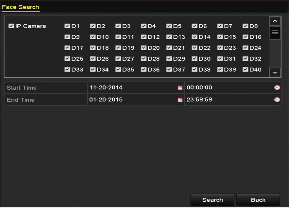
45 2. Enable the VCA detection and configure the rule settings. Please refer to the User Manual for detailed instructions. Please refer to the User Manual for detailed instructions to set the VCA rules. VCA Search The NVR supports the VCA search for the behavior analysis, face capture, people counting and heat map. Face Search: Search the captured face picture results triggered by face detection. Behavior Search: Search and view the behavior detection (including the line crossing detection, intrusion detection, unattended baggage detection, etc.) results in pictures and video files. People Counting: Calculate the number of people entered or exited from a certain configured area and show in chart of daily/weekly/monthly/annual report. Heat Map: Analyze the visit times and dwell time of customers in a configured area. The heat map is a graphical representation of data represented by colors. Please refer to the User Manual for detailed instructions of VCA Search. 44
46
Quick Operation Guide of LTN7700/7600 Series NVR
 Quick Operation Guide of LTN7700/7600 Series NVR UD.6L0202B0042A02 Thank you for purchasing our product. If there is any question or request, please do not hesitate to contact dealer. This manual is applicable
Network Video Recorder Quick Start Guide
 Network Video Recorder Quick Start Guide UD.6L0202B1501A02 TABLE OF CONTENTS NVR Pre-Installation... 3 NVR Installation... 3 Hard Disk Installation... 4 Front Panel... 8 Rear Panel... 15 Peripheral Connections...
DS-7200HVI/HFI-SH Series DVR Quick Operation Guide
 DS-7200HVI/HFI-SH Series DVR Quick Operation Guide UD.6L0202B0019A01 Thank you for purchasing our product. If there is any question or request, please do not hesitate to contact dealer. This manual is
DINOX&Digital&Video&Recorder&
 DINOX&Digital&Video&Recorder& & & & & & & & & & &&&Quick&Operation&Guide& UD.7L0X02B1228B01& Thank you for purchasing our product. If there is any question or request, please do not hesitate to contact
Digital Video Recorder
 Digital Video Recorder Quick Operation Guide UD.6L0202B0067A02 Thank you for purchasing our product. If there is any question or request, please do not hesitate to contact dealer. This manual is applicable
EVD-L04/100A1-960, EVD-L08/200A1-960 and. EVD-L16/400A1-960 DVRs. Quick Operation Guide
 EVD-L04/100A1-960, EVD-L08/200A1-960 and EVD-L16/400A1-960 DVRs Quick Operation Guide Thank you for purchasing our product. If there is any question or request, please do not hesitate to contact dealer.
Digital Video Recorder. Quick Start Guide
 Digital Video Recorder Quick Start Guide TABLE OF CONTENTS Chapter 1Description of Panels... 6 1.1 Front Panel... 6 1.2 Rear Panel... 7 Chapter 2Installation and Connections... 9 2.1 DVR Installation...
DS-9600NI-XT Series NVR. Technical Specification
 DS-9600NI-XT Series NVR Notices The information in this documentation is subject to change without notice and does not represent any commitment on behalf of HIKVISION. HIKVISION disclaims any liability
DS-7200HFI-SL Series DVR. Technical Specification
 DS-7200HFI-SL Series DVR Technical Specification Notices The information in this documentation is subject to change without notice and does not represent any commitment on behalf of HIKVISION. HIKVISION
DS-7204/7208/7216HVI-ST Series DVR Technical Manual
 DS-7204/7208/7216HVI-ST Series DVR Technical Manual Notices The information in this documentation is subject to change without notice and does not represent any commitment on behalf of HIKVISION. HIKVISION
ES-RN A ES-RN A Series NVR. Technical Specification
 ES-RN080802-A ES-RN160802-A Series NVR Technical Specification NOTICES The information in this documentation is subject to change without notice and does not represent any commitment on behalf of EMERSON.
DS-7200HVI-ST/RW Series DVR. Technical Manual
 DS-7200HVI-ST/RW Series DVR Technical Manual Notices The information in this documentation is subject to change without notice and does not represent any commitment on behalf of HIKVISION. HIKVISION disclaims
DS-9600NI-XT NVR Series
 DS-9600NI-XT NVR Series Introduction: DS-9600NI-XT series NVR (Network Video Recorder) is a new generation recorder developed by Hikvision independently. Combined with multiple advanced technologies, such
ARCHITECTURAL AND ENGINEERING SPECIFICATION DIVISION - LEVEL 1 28 ELECTRONIC SAFETY AND SECURITY LEVEL ELECTRONIC SURVEILLANCE LEVEL
 Eventys EX 4 CRDN0410-PA Network Video Recorder (NVR) ARCHITECTURAL AND ENGINEERING SPECIFICATION DIVISION - LEVEL 1 28 ELECTRONIC SAFETY AND SECURITY LEVEL 2 28 20 00 ELECTRONIC SURVEILLANCE LEVEL 3 28
EVD-L04/100A1-960 EVD-L08/200A1-960 EVD-L16/400A1-960
 EVD-L04/100A1-960 EVD-L08/200A1-960 EVD-L16/400A1-960 www.eurovideo-cctv.com Main Features Main stream supports encoding at up to WD1 resolution in real time and sub stream at CIF/QCIF resolution. Simultaneous
RF Series Real Time Triple Technology Recorders 960H EZHD IP. EZHD-TRF4 EZHD-TRF8 EZHD-TRF16 Quick Installation Guide
 RF Series Real Time Triple Technology Recorders 960H EZHD IP EZHD-TRF4 EZHD-TRF8 EZHD-TRF16 Quick Installation Guide TABLE OF CONTENTS DVR Pre-Installation... 3 DVR Installation... 3 Front Panels... 4
Digital Video Recorder. User Manual UD01394B
 Digital Video Recorder User Manual UD01394B User Manual COPYRIGHT 2016 Hangzhou Hikvision Digital Technology Co., Ltd. ALL RIGHTS RESERVED. Any and all information, including, among others, wordings, pictures,
LOCAL MONITORING RECORDING HARDDISK MANAGEMENT ALARM & EXCEPTION BACKUP
 FEATURES User-friendly GUI for easy operation Up to 1024 768 resolution Simultaneous VGA and 4CIF/2CIF/CIF resolution Normal and event recording parameters configurable per individual camera Partial digital
NX-series User Manual
 NX-series User Manual http://www.iviewtech.com 1 CONTENT INDEX 1 NX-SERIES OVERVIEW... 4 1.1. NX-Series Features 4 1.2. NVR CONTROL PANEL 5 1.3. NVR BACK PANEL 5 2 GETTING STARTED... 8 3 LIVE VIEW... 10
B. The specified product shall be manufactured by a firm whose quality system is in compliance with the I.S./ISO 9001/EN 29001, QUALITY SYSTEM.
 VideoJet 8000 8-Channel, MPEG-2 Encoder ARCHITECTURAL AND ENGINEERING SPECIFICATION Section 282313 Closed Circuit Video Surveillance Systems PART 2 PRODUCTS 2.01 MANUFACTURER A. Bosch Security Systems
TruVision NVR 22 A&E Specifications
 TruVision NVR 22 A&E Specifications A. Network Video Recorder 1. The Network Video Recorder with Ethernet connectivity shall be as manufactured by Interlogix or an approved equal. The TVN 22 shall require
TVE-DEC10 IP Video Decoder User Manual
 TVE-DEC10 IP Video Decoder User Manual P/N 1072583B-EN REV 1.0 ISS 16OCT12 Copyright Trademarks and patents Manufacturer Certification FCC compliance European Union directives Contact information 2012
Video Series. HCS-4311M Professional Mixed Matrix for Conference 8.2. HCS-3313C High Quality Speed Dome Camera (ceiling) 8.5
 8.5") Video Video Series Series Video Tracking System 8.2 HCS-4311M Professional Mixed Matrix for Conference 8.2 HCS-3313C High Quality Speed Dome Camera (ceiling) 8.5 HCS-3313D High Quality Speed Dome Camera
Video Video Series Series Video Tracking System 8.2 HCS-4311M Professional Mixed Matrix for Conference 8.2 HCS-3313C High Quality Speed Dome Camera (ceiling) 8.5 HCS-3313D High Quality Speed Dome Camera
EL-NVR. Quick Start Guide
 EL-NVR Quick Start Guide ABOUT THIS DOCUMENT This document includes instructions for basic operating the EL-NVR 5-Megapixel Series Network Video Recorder. ELECTROMAGNETIC COMPATIBILITY (EMC) This equipment
Part 1 Basic Operation
 This product is a designed for video surveillance video encode and record, it include H.264 video Compression, large HDD storage, network, embedded Linux operate system and other advanced electronic technology,
DS-6401HDI Series Decoder Server USER MANUAL. Version 1.0
 DS-6401HDI Series Decoder Server USER MANUAL Version 1.0 Hikvision Network Digital Video Recorder User s Manual This manual, as well as the software described in it, is furnished under license and may
CI-218 / CI-303 / CI430
 CI-218 / CI-303 / CI430 Network Camera User Manual English AREC Inc. All Rights Reserved 2017. l www.arec.com All information contained in this document is Proprietary Table of Contents 1. Overview 1.1
HDBaseT Extender Set 100m User Guide
 HDBaseT Extender Set 100m User Guide Model CM-BT10-TXRX100 Last modified: 09/29/16 Doc ID - 620 Rev 04 Copyright Trademarks and patents Manufacturer Contact information 29SEP16 Clare Controls, LLC. All
SCode V3.5.1 (SP-601 and MP-6010) Digital Video Network Surveillance System
 Digital Video Network Surveillance System") V3.5.1 (SP-601 and MP-6010) Digital Video Network Surveillance System Core Technologies Image Compression MPEG4. It supports high compression rate with good image quality and reduces the requirement of
V3.5.1 (SP-601 and MP-6010) Digital Video Network Surveillance System Core Technologies Image Compression MPEG4. It supports high compression rate with good image quality and reduces the requirement of
USER GUIDE. AXIS T8640 Ethernet Over Coax Adaptor PoE+ ENGLISH
 USER GUIDE AXIS T8640 Ethernet Over Coax Adaptor PoE+ ENGLISH Electromagnetic Compatibility (EMC) This equipment generates, uses and can radiate radio frequency energy and, if not installed and used in
HDBaseT Compact Extender Set 70m User Guide
 HDBaseT Compact Extender Set 70m User Guide Model HDBaseT-C.tx70 and HDBaseT-C.rx70 Last Modified: 09/29/2016 Doc ID - 1328 Rev 04 Copyright Trademarks and patents Manufacturer Contact information 29SEP16
DS-6900UDI Series Decoder
 DS-6900UDI Series Decoder Hikvision s DS-6900UDI Series Decoders support resolutions of up to 4K (3,840 x 2,160 @ 30 Hz) via HDMI output interfaces. These decoders feature 16-ch decoding at 12 MP, as well
HD TVI TURBO HD DVR Hikvision DS 7216HGHI SH/A (16ch, H.264, HDMI, VGA)
") HD TVI TURBO HD DVR Hikvision DS 7216HGHI SH/A (16ch, 1080p@12fps, H.264, HDMI, VGA) Code: M75216 Front view Rear view The included remote control http://www.dipolnet.com/document print M75216.htm 1/5
HD TVI TURBO HD DVR Hikvision DS 7216HGHI SH/A (16ch, 1080p@12fps, H.264, HDMI, VGA) Code: M75216 Front view Rear view The included remote control http://www.dipolnet.com/document print M75216.htm 1/5
VERINT EDGEVR 200 INTELLIGENT DIGITAL VIDEO RECORDER (Rev A)
") VERINT EDGEVR 200 INTELLIGENT DIGITAL VIDEO RECORDER (Rev A) TECHNICAL SPECIFICATIONS SECURITY SYSTEM DIVISION 28 ELECTRONIC SAFETY AND SECURITY LEVEL 1 28 20 00 ELECTRONIC SURVEILLANCE LEVEL 2 28 23 00
VERINT EDGEVR 200 INTELLIGENT DIGITAL VIDEO RECORDER (Rev A) TECHNICAL SPECIFICATIONS SECURITY SYSTEM DIVISION 28 ELECTRONIC SAFETY AND SECURITY LEVEL 1 28 20 00 ELECTRONIC SURVEILLANCE LEVEL 2 28 23 00
1. Get support Attention Safety Caution Applications View Cameras on Screen (ex. HD TV or PC monitor) 3. Change Time Zone 5
 3. Change Time Zone 5") 1. Get support 1 2. Attention 1 3. Safety Caution 1 4. Applications 1 5. View Cameras on Screen (ex. HD TV or PC monitor) 3 Change Time Zone 5 6. Installation Guide for ONWOTE Cameras 6 7. View Cameras
1. Get support 1 2. Attention 1 3. Safety Caution 1 4. Applications 1 5. View Cameras on Screen (ex. HD TV or PC monitor) 3 Change Time Zone 5 6. Installation Guide for ONWOTE Cameras 6 7. View Cameras
Model#: IN-DI2MIRF 2MP Indoor Dome with True Day/Night, IR, Basic WDR, Fixed lens
 Model#: IN-DI2MIRF 2MP Indoor Dome with True Day/Night, IR, Basic WDR, Fixed lens Hardware User Manual (PoE) Ver.2013/01/17 Table of Contents 0. Precautions 3 1. Introduction 4 Package Contents...4 Features
DATA/SPEC SHEET 16-CHANNEL HYBRID DIGITAL VIDEO RECORDER. Built for Reliability, Usability, and Low Cost of Ownership.
 DATA/SPEC SHEET V920 KOLLECTOR - PRODUCT FORCE DESCRIPTION 16-CHANNEL HYBRID DIGITAL VIDEO RECORDER Configured with ViconNet Video Management Software (VMS) Scalable from one to hundreds of recorders Support
User Manual of DS-C10S Series Video Wall Controller. DS-C10S Series Video Wall Controller. User Manual (V2.0) UD.6L0203D1184A01
 UD.6L0203D1184A01") User Manual of DS-C10S Series Video Wall Controller DS-C10S Series Video Wall Controller User Manual (V2.0) UD.6L0203D1184A01 0 User Manual of DS-C10S Series Video Wall Controller User Manual COPYRIGHT
User Manual of DS-C10S Series Video Wall Controller DS-C10S Series Video Wall Controller User Manual (V2.0) UD.6L0203D1184A01 0 User Manual of DS-C10S Series Video Wall Controller User Manual COPYRIGHT
SCode V3.5.1 (SP-501 and MP-9200) Digital Video Network Surveillance System
 Digital Video Network Surveillance System") V3.5.1 (SP-501 and MP-9200) Digital Video Network Surveillance System Core Technologies Image Compression MPEG4. It supports high compression rate with good image quality and reduces the requirement of
V3.5.1 (SP-501 and MP-9200) Digital Video Network Surveillance System Core Technologies Image Compression MPEG4. It supports high compression rate with good image quality and reduces the requirement of
ACM-1431 Series. IP IR D/N CCD Outdoor PoE Bullet Camera. (DC 12V / PoE) Ver. 2012/3/12
 Ver. 2012/3/12") ACM-1431 Series IP IR D/N CCD Outdoor PoE Bullet Camera (DC 12V / PoE) Ver. 2012/3/12 Table of Contents 0. Precautions 3 1. Introduction 4 Package Contents... 4 Features and Benefits... 5 Safety Instructions...
ACM-1431 Series IP IR D/N CCD Outdoor PoE Bullet Camera (DC 12V / PoE) Ver. 2012/3/12 Table of Contents 0. Precautions 3 1. Introduction 4 Package Contents... 4 Features and Benefits... 5 Safety Instructions...
USER S MANUAL (1/2) (Functions and connections)
 (Functions and connections)") English USER S MANUAL (1/2) (Functions and connections) WIDE PLASMA DISPLAY P42VCA30W/P42VCA30E WITH OPTIONAL VIDEOBOARD (P-TE1100/P-TE1110/P-TE1120/P-TE1130) HE4VS01W/HE4VS01E WITH OPTIONAL VIDEOBOARD
English USER S MANUAL (1/2) (Functions and connections) WIDE PLASMA DISPLAY P42VCA30W/P42VCA30E WITH OPTIONAL VIDEOBOARD (P-TE1100/P-TE1110/P-TE1120/P-TE1130) HE4VS01W/HE4VS01E WITH OPTIONAL VIDEOBOARD
Network Camera Installation Guide
 Network Camera Installation Guide 1.3 MP Budget Mini-Bullet Camera Model CV-B13B10-ODI Last modified: 09/29/16 Doc ID - 335 REV 05 Copyright 29SEP16 Clare Controls. All rights reserved. This document
MAGICLiteSeries-16CH1080pDVRSystem-SupportsEX- SDI/HD-SDI/960H/Analog/IP
 MAGICLiteSeries-16CH1080pDVRSystem-SupportsEX- SDI/HD-SDI/960H/Analog/IP EX-SDI Magic Lite 1080p 16 CH MagicDVRdetectsAnalog/960H/EX-SDI/HD-SDIcamerasautomatically Records up to 4 IP cameras REAL-TIME
Disclaimer. Warning and Caution CAUTION!
 Disclaimer While every effort has been made to ensure that the information contained in this guide is accurate and complete, no liability can be accepted for any errors or omissions NUVICO reserves the
OPERATING INSTRUCTIONS TOM-0431IP
 OPERATING INSTRUCTIONS TOM-0431IP Table of Contents FCC Information -------------------------------------------------------------------- 2 Safety and Environmental Precautions ------------------------------------------------
DS-2CE56D0T-IRF HD1080p IR Turret Camera
 DS-2CE56D0T-IRF HD1080p IR Turret Camera Key Features 2 megapixel high performance CMOS Analog HD output, up to 1080p resolution Day/Night switch Smart IR Up to 20 m IR distance Switchable TVI/AHD/CVI/CVBS
CM-S23349SV. Vari-Focal IR Bullet Camera
 Vari-Focal IR Bullet Camera User s Guide CM-S23349SV SAFETY PRECAUTIONS WARNING 1. Be sure to use only the standard adapter that is specified in the specification sheet. Using any other adapter could cause
MAGICUSeries-32CHDVR4Koutput-SupportsEX-SDI/ HD-SDI/HD-TVI/A-HD/960H/Analog/IP
 MAGICUSeries-32CHDVR4Koutput-SupportsEX-SDI/ HD-SDI/HD-TVI/A-HD/960H/Analog/IP Magic U 1080p 3MP 32 CH MagicUDVRdetectsAnalog/960H/HD-TVI/A-HD/EX-SDI/HD-SDIcameras automatically Records up to 4 IP cameras
DS-6400HDI-T Series Decoder Features and Functions
 DS-6400HDI-T Series Decoder Features and Functions Supports private H.264, standard H.264, MJPEG, MPEG2 and MPEG4 video stream formats High-definition video output via DVI/VGA/HDMI interface and standard-definition
Model#: IN-MDRI3MF. Hardware User Manual. 3MP Indoor Mini Dome with Basic WDR, Fixed lens. (PoE) Ver. 2013/02/04
 Ver. 2013/02/04") Model#: IN-MDRI3MF 3MP Indoor Mini Dome with Basic WDR, Fixed lens Hardware User Manual (PoE) Ver. 2013/02/04 Table of Contents 0. Precautions 3 1. Introduction 4 Package Contents... 4 Features and Benefits...
Model#: IN-MDRI3MF 3MP Indoor Mini Dome with Basic WDR, Fixed lens Hardware User Manual (PoE) Ver. 2013/02/04 Table of Contents 0. Precautions 3 1. Introduction 4 Package Contents... 4 Features and Benefits...
THD601DC Set-top box
 THD601DC Set-top box Contents 1. Safety... 1 2. Appearance... 2 3. Rear Panel Connection... 3 4. Remote... 4 5 First Time Set-Up... 7 6. Network Settings... 8 6.1 Available Networks and Checking Current
CM-S38901SV TVL IR Long Range camera
 5 40 TVL IR Long Range camera User s Guide CM-S38901SV SAFETY PRECAUTIONS WARNING 1. Be sure to use only the standard adapter that is specified in the specification sheet. Using any other adapter could
HDBaseT Receiver 70m User Guide
 HDBaseT Receiver 70m User Guide Model CM-BT10-RX70 Last modified: 10/20/16 Doc ID - 351 Rev 03 Copyright Trademarks and patents Manufacturer Contact information 20OCT16 Clare Controls, LLC. All rights
NETWORK VIDEO RECORDER Quick Manual
 NETWORK VIDEO RECORDER Quick Manual SRN-4000 English Features The product records video and audio from network cameras to a hard disk, and enables playback from the hard disk. It also provides remote monitoring
MAGICUSeries-4CH1080pDVRSystem4Kouput- SupportsEX-SDI/HD-SDI/HD-TVI/A-HD/960H/Analog/ IP
 MAGICUSeries-4CH1080pDVRSystem4Kouput- SupportsEX-SDI/HD-SDI/HD-TVI/A-HD/960H/Analog/ IP Magic U 1080p 3MP 4 CH MagicUDVRdetectsAnalog/960H/HD-TVI/A-HD/EX-SDI/HD-SDIcameras automatically Records up to
IPS 2400 SMAVIA Appliance for up to 24 IP Channels, 8 3.5" HDD, 3 HU
 PRELOADED Panomera Recording Redundant PSU 1) Storage System Open Platform The is a high performance appliance with a processing capacity for up to 24 IP video channels and an integrated storage system.
EdgeConnect Module Quick Start Guide ITERIS INNOVATION FOR BETTER MOBILITY
 EdgeConnect Module Quick Start Guide ITERIS INNOVATION FOR BETTER MOBILITY 493456301 Rev B April 2009 Table of Contents Installation... 1 Setup... 2 Operation... 4 Live Video... 4 Video Settings... 5 Network
USER GUIDE FOR NETmc MARINE X-Ops
 USER GUIDE FOR NETmc MARINE X-Ops Rev.2.2 Firmware v.1.2.8 X-Ops, 1.2.9 Pipeline September 2013 NETmc Marine X-Ops Manual-Rev.2.2 September 2013 1 of 17 Contents 1. Introduction... 3 1.1 Multi-channel
BY-HPE11KTA. Operating Instructions. Coaxial - LAN Converter with PoE function. Indoor Use Only. Model No. Attached Installation Guide
 Operating Instructions Coaxial - LAN Converter with PoE function Model No. Indoor Use Only BY-HPE11KTA Attached Installation Guide Before attempting to connect or operate this product, please read these
Model: UHD41-ARC. Installation Guide
 Model: UHD41-ARC Installation Guide 1 Safety Information: Electrical safety Use only the power supplies and the AC power cord that were included with your product. Use of other power supplies could damage
Outdoor IR Audio Camera
 Outdoor IR Audio Camera User s Guide CM-S22326BW-AD SAFETY PRECAUTIONS WARNING 1. Be sure to use only the standard adapter that is specified in the specification sheet. Using any other adapter could cause
Network Video Recorder NVR
 English Network Video Recorder NVR16-7200 M16720H011113E1 Before You Begin Introduction FCC Verification NOTE: This equipment has been tested and found to comply with the limits for Class B digital device,
MPEG4 Digital Recording System THE VXM4 RANGE FROM A NAME YOU CAN RELY ON
 MPEG Digital Recording System THE VXM RANGE FROM A NAME YOU CAN RELY ON 8 6 THE FIRST CONCEPT PRO DIGITAL RECORDING SYSTEM DESIGNED TO OUR SPECIFICATION AND FOCUSED ON YOUR REQUIREMENTS VXM KEY FEATURES
MAGICUSeries-16CHDVR4Koutput-SupportsEX-SDI/ HD-SDI/HD-TVI/A-HD/960H/Analog/IP
 MAGICUSeries-16CHDVR4Koutput-SupportsEX-SDI/ HD-SDI/HD-TVI/A-HD/960H/Analog/IP EX-SDI Magic U 1080p 16 CH MagicUDVRdetectsAnalog/960H/HD-TVI/A-HD/EX-SDI/HD-SDIcameras automatically Records up to 4 IP cameras
Analogue HD Monitoring Set: 8-Channel Video Recorder + 4 Outdoor Cameras
 Page 1 of 5 Complete set with 8-channel recorder, 4 outdoor cameras, 1 TB hard disk drive, 5 power supply units and accessories Incl. 1 TB hard disk drive for approx. 2 weeks of continuous recording Simple
MAX T200 HD QUICK INSTALLATION GUIDE
 MAX T200 HD QUICK INSTALLATION GUIDE MAX T200 HD QUICK INSTALLATION GUIDE CONTENT receiver BATTERIES x 2 REMOTE CONTROL Quick installation guide Quick Installation Guide The lightning flash with arrowhead
Table of Contents FCC COMPLIANCE STATEMENT... 4 WARNINGS AND PRECAUTIONS... 4 WARRANTY... 5 STANDARD WARRANTY... 5 TWO YEAR WARRANTY... 5 DISPOSAL...
 1 Table of Contents FCC COMPLIANCE STATEMENT... 4 WARNINGS AND PRECAUTIONS... 4 WARRANTY... 5 STANDARD WARRANTY... 5 TWO YEAR WARRANTY... 5 DISPOSAL... 6 1. INTRODUCTION... 7 FEATURES... 7 2. CONNECTIONS
A. All equipment and materials used shall be standard components that are regularly manufactured and used in the manufacturer s system.
 ENDURA NET5308T VIDEO ENCODER TECHNICAL SPECIFICATIONS SECURITY SYSTEM DIVISION 28 ELECTRONIC SAFETY AND SECURITY LEVEL 1 28 20 00 ELECTRONIC SURVEILLANCE LEVEL 2 28 23 00 VIDEO SURVEILLANCE LEVEL 3 28
Thank you for purchasing our product. If there is any question or request, please do not hesitate to contact us. This manual may contain technical or
 22-inch LCD Display Unit ST-HDLED2.5 User Manual www.securitytronix.com Thank you for purchasing our product. If there is any question or request, please do not hesitate to contact us. This manual may
MPEG4 Mobile DVR User Manual
 MPEG4 Mobile DVR User Manual 1 MPEG4 Embedded User Manual A. Installation Environment Installation Guideline In order to ensure the safety with the DVR product and maximize product performance, keep DVR
FEATURES MPEG4/MJPEG DVR
 FEATURES MPEG4/MJPEG DVR Technology Compression format providing crystal clear images with real time performance. Multiplex Allow live display, record, playback, backup and network operation at the same
-TECH DIGITAL. Explore The High DefinitionWorld. Website: Hot Line: [US] USER MANUAL
![-TECH DIGITAL. Explore The High DefinitionWorld. Website: Hot Line: [US] USER MANUAL](/thumbs/80/80689593.jpg "-TECH DIGITAL. Explore The High DefinitionWorld. Website: Hot Line: [US] USER MANUAL") -TECH DIGITAL Explore The High DefinitionWorld Website: www.jtechdigital.com Hot Line: 1-888-610-2818[US] USER MANUAL J-Tech Digital ProAV H.264 Encoder/Decoder Many to Many HDMI Extender RoHS 1 Operating
-TECH DIGITAL Explore The High DefinitionWorld Website: www.jtechdigital.com Hot Line: 1-888-610-2818[US] USER MANUAL J-Tech Digital ProAV H.264 Encoder/Decoder Many to Many HDMI Extender RoHS 1 Operating
Vocia WR-1. Operation Manual
 Vocia WR-1 Operation Manual January 2012 Biamp Systems, 9300 SW Gemini Drive, Beaverton, Oregon 97008 U.S.A. (503) 641-7287 www.biamp.com TABLE OF CONTENTS VOCIA WALL REMOTE 1 (WR-1) FEATURES....3 FRONT
Provide144ch FREE CMS software. Time / Event / POS / Thumbnail / Panorama
 20CH DVR Real time and Playback Search Mode: Time / Event / POS / Real HD Live Display and Playback Thumbnail / Panorama Full Graphic User Interface(Multiple High-Resolution & High-Quality Language Support)
Hardware User s Manual
 Hardware User s Manual Megapixel Day & Night Economy Bullet Network Camera English 1 Table of Contents Before You Use This Product... 2 Regulatory Information... 3 Chapter 1 - Package Contents... 4 Chapter
Contents. Disclaimer of Product and Services
 Instruction Manual Contents FCC COMPLIANCE STATEMENT... 3 WARNINGS AND PRECAUTIONS... 3 WARRANTY... 4 STANDARD WARRANTY... 4 THREE YEAR WARRANTY... 4 DISPOSAL... 4 INTRODUCTION... 5 FEATURES... 5 GO KMU-100
PS600 Digital Visualizer. User Manual. English - 0
 PS600 Digital Visualizer User Manual English - 0 Table of Content COPYRIGHT INFORMATION... 3 CHAPTER 1 PRECAUTIONS... 4 SAFETY PRECAUTIONS... 5 FCC WARNING... 5 EN55022 (CE RADIATION) WARNING... 5 CHAPTER
IRIG-B PTP Clock Converter Output Module Hardware Installation Manual
 IRIG-B PTP Clock Converter Output Module Hardware Installation Manual Kyland Technology Co., LTD. Publication Date: May 2012 Version: V1.2 Customer Service Hotline: (+8610) 88796676 FAX: (+8610) 88796678
QUICK START GUIDE QT ANALOG HD CAMERA & DVR BUNDLE ENGLISH
 QUICK START GUIDE QT ANALOG HD CAMERA & DVR BUNDLE ENGLISH Table of Contents Welcome What s Included...3 Understanding your DVR...4 Get Connected Registration...5 Connect Your Cameras...5 Connect DVR to
DC162 Digital Visualizer. User Manual. English - 1
 DC162 Digital Visualizer User Manual English - 1 Table of Contents CHAPTER 1 PRECAUTIONS... 5 CHAPTER 2 PACKAGE CONTENT... 7 CHAPTER 3 PRODUCT OVERVIEW... 8 3.1 PRODUCT INTRODUCTION... 8 3.2 I/O CONNECTION...
Camera 220C Document Camera User s Guide
 Camera 220C Document Camera User s Guide #401-220C-00 Table of Contents TABLE OF CONTENTS... 0 TABLE OF CONTENTS... 1 COPYRIGHT INFORMATION... 2 CHAPTER 1 PRECAUTIONS... 3 CHAPTER 2 PACKAGE CONTENT...
MAGICQLSeries-4CH1080pDVRSystem-SupportsEX- SDI/HD-SDI/960H/Analog/IP
 MAGICQLSeries-4CH1080pDVRSystem-SupportsEX- SDI/HD-SDI/960H/Analog/IP EX-SDI 1080p 4 CH MagicDVRdetectsAnalog/960H/EX-SDI/HD-SDIcamerasautomatically Records up to 1 IP cameras REAL-TIME Live / 1080p@ Pentaplex
Video Extender DS128 DSRXL. Instruction Manual. 8-Port Cat5 VGA Digital Signage Broadcaster with RS232 and Audio
 DS128 DSRXL Instruction Manual Video Extender 8-Port Cat5 VGA Digital Signage Broadcaster with RS232 and Audio Cat5 VGA Digital Signage Receiver with RS232 and Audio FCC Compliance Statement This equipment
Disclaimer of Product & Services The information offered in this instruction manual is intended as a guide only. At all times, Datavideo Technologies
 TC-100 Table of Contents FCC COMPLIANCE STATEMENT... III WARNINGS AND PRECAUTIONS... III WARRANTY... V STANDARD WARRANTY... V THREE YEAR WARRANTY... V DISPOSAL... VI INTRODUCTION... 1 FEATURES... 1 HOW
HCS-8131M Professional Audio & Video Recorder for Conference
 HCS-8131M Professional Audio & Video Recorder for Conference The ability of remote upgrading through network With DSP processing chips, embedded operating system, stable and reliable due to immunity to
P XGA TFT Monitor. User s Manual
 P6151 15 XGA TFT Monitor User s Manual Disclaimers This manual has been carefully checked and believed to contain accurate information. Axiomtek Co., Ltd. assumes no responsibility for any infringements
DDW36C Advanced Wireless Gateway - Safety and Installation Product Insert. Federal Communications Commission (FCC) Interference Statement
 Interference Statement") DDW36C Advanced Wireless Gateway - Safety and Installation Product Insert Federal Communications Commission (FCC) Interference Statement This equipment has been tested and found to comply with the limits
DDW36C Advanced Wireless Gateway - Safety and Installation Product Insert Federal Communications Commission (FCC) Interference Statement This equipment has been tested and found to comply with the limits
TruVision High Definition TVI Vandal Dome Installation Guide
 TruVision High Definition TVI Vandal Dome Installation Guide TVD-2402/TVD-4402 TVD-2404/TVD-4404 P/N 1072937-EN REV A ISS 12MAR15 Content Product overview 3 Camera description 5 Installation 7 Programming
DVDO VS4 HDMI Switch. User s Guide How to install, set up, and use your new DVDO product
 DVDO VS4 HDMI Switch User s Guide How to install, set up, and use your new DVDO product TABLE OF CONTENTS Table of Contents... 1 Introduction... 1 Installation and Set-Up... 2 Remote Control Operation...
O2D60M User s Manual. Network Camera Manual (O2D60M)
") Network Camera Manual (O2D60M) Directions Be careful not to cause any physical damage by dropping or throwing the camera. Especially keep the device out of reach from children. Do not disassemble the camera.
Network Camera Manual (O2D60M) Directions Be careful not to cause any physical damage by dropping or throwing the camera. Especially keep the device out of reach from children. Do not disassemble the camera.
RS Part No Instruction Manual Solid State DVR. (Single Chanel for Mobile) SSD01CA
 SSD01CA") RS Part No. 696-1210 Instruction Manual Solid State DVR (Single Chanel for Mobile) RS PART NO.: 696-1210 MJPEG 1CH CAR DVR (Compact size 1ch Stand Alone DVR) Simple & Max Low cost but great guality MJPEG
RS Part No. 696-1210 Instruction Manual Solid State DVR (Single Chanel for Mobile) RS PART NO.: 696-1210 MJPEG 1CH CAR DVR (Compact size 1ch Stand Alone DVR) Simple & Max Low cost but great guality MJPEG
QUICK START GUIDE. IP Camera & NVR Bundle ENGLISH
 QUICK START GUIDE IP Camera & NVR Bundle ENGLISH Table of Contents Welcome What s Included...3 Understanding Your NVR...4 Get Connected Registration...5 Connect Your Cameras...5 Connect Your NVR...6 Powering
Z-IP Stream 004/008. User Guide and Installation Manual. Four or Eight Input QAM Encoder / Modulator
 Z-IP Stream 004/008 User Guide and Installation Manual Four or Eight Input QAM Encoder / Modulator MPEG-2 / H.264 HD ENCODER with QAM /IP/ & ASI Outputs Contents Safety Precautions... 3 Package Contents...
Remote Control. degraded, causing unreliable operation. The recommended effective distance for remote operation is about 16 feet (5 meters).
.") Media Streaming Sound Bar RTS736W User Manual Remote Control using the remote control Point the remote control at the REMOTE SENSOR located on the unit (see Front Panel illustration for precise location).
Media Streaming Sound Bar RTS736W User Manual Remote Control using the remote control Point the remote control at the REMOTE SENSOR located on the unit (see Front Panel illustration for precise location).
Product Guide Specification
 March 2017 Product Guide Specification Specifier Notes: This product guide specification is written according to the Construction Specifications Institute (CSI) 3-Part Format, based on MasterFormat 2016
16CH 1080p HD-SDI Security MAGIC Lite Series DVR System - Auto detects Analog/960H/HD-SDI
 HD-SDI Magic Lite 1080p 16 CH Magic DVR detects Analog / 960H / HD-SDI camera automatically. H.264 High Compression CODEC Programmable Spot Out iphone Android remote view App Available. Crystal clear 1080p
23.6 & 27 & 32-INCH TFT-LCD IP PUBLIC VIEW MONITOR
 23.6 & 27 & 32-INCH TFT-LCD IP PUBLIC VIEW MONITOR INSTRUCTION MANUAL Please read this manual thoroughly before use, and keep it handy for future reference. 1 TABLE OF CONTENTS 1. GENERAL INFORMATION...
Magic U Series 4CH Octa-brid DVR System, 4K Output, 2 HDD slots, esata, 4CH Audio
 Magic U DVR detects Analog 960H HD-TVI A-HD EX-SDI HD-SDI cameras automatically Records up to 4 IP cameras REAL-TIME Live Programmable Multi-CH HD Spot Out 4K Video output Touch Interface iphone Android
User Manual. AtlonA COMPOSITE VIDEO (BNC) + STEREO AUDIO TO HDMI VIDEO FORMAT CONVERTER AND SCALER AT-HD120
 + STEREO AUDIO TO HDMI VIDEO FORMAT CONVERTER AND SCALER AT-HD120") User Manual AtlonA COMPOSITE VIDEO (BNC) + STEREO AUDIO TO HDMI VIDEO FORMAT CONVERTER AND SCALER AT-HD120 TABLE OF CONTENTS 1. Introduction... 3 2. Package Contents... 3 3. Features... 3 4. Specification...
User Manual AtlonA COMPOSITE VIDEO (BNC) + STEREO AUDIO TO HDMI VIDEO FORMAT CONVERTER AND SCALER AT-HD120 TABLE OF CONTENTS 1. Introduction... 3 2. Package Contents... 3 3. Features... 3 4. Specification...
Instruction Guide. The TV Jockey Computer Monitor TV Tuner with Remote COMP2VGATVGB. The Professionals Source For Hard-to-Find Computer Parts
 VIDEO ADAPTER The TV Jockey Computer Monitor TV Tuner with Remote COMP2VGATVGB Instruction Guide * Actual product may vary from photo The Professionals Source For Hard-to-Find Computer Parts FCC COMPLIANCE