Titan. Operation Manual. by Ian Dennis
|
|
|
- Lorraine Richardson
- 6 years ago
- Views:
Transcription
1
2
3 Titan by Ian Dennis This manual is also available as 'on-line help' from the Titan Control Panel app. You can access the on-line help from the 'Help' button in the top right-hand corner of the app.
4 Table of Contents Part 1 General information 2 Part 2 Introduction to Titan 6 1 Features System... requirements 7 3 About... this manual 7 Part 3 Quick start guides 1 Quick... start for Mac 10 2 Quick... start for Windows 10 Part 4 Installation procedures 1 Mac... installation 12 2 Windows... installation 14 3 Operating... multiple units 19 4 Software... and firmware updates 19 Part 5 Titan hardware 1 Signal... path architecture 22 Analogue... inputs Overkiller... High-pass... filter MS... matrix Digital... inputs Sample-rate... converter DI... synchronization Analogue... outputs Digital... outputs Sample-rate... converter Word-length... DO... synchronization Output... mixers and routing matrix Assignable... level control Headphone... outputs Metering... system MDIO... expansion slot Synchronization Front... panel 29 4 Rear... panel 31 5 Stand-alone... operation 32 6 Rack... mounting 32 Part 6 Titan software Fuses... and ratings 32 34
5 1 Titan... Control Panel app 34 Unit... settings Inputs... tab Outputs... tab Mixer... tabs Titan... drivers 39 3 Verifile... Checker app 40 Part 7 Technical topics 1 Stability... and latency 44 2 Clocking... and jitter 45 3 Dither... and noise-shaping 47 4 Verifile Analogue... interconnections 52 6 Digital... interconnections 54 Part 8 Specifications 58 Index 64 44
6
7 Part 1 General information
8 1 General information Manual revision history Rev Date th December rd January 2018 Author I.G.Dennis I.G.Dennis Notes Product launch Application version 1.20 and above Support contacts Prism Media Products Limited The Old School Stretham Cambridge CB6 3LD UK Prism Media Products Inc 45 Pine Street, Suite 1 Rockaway NJ USA Telephone: Fax: Telephone: Fax: tech.support@prismsound.com Web: Or contact your local Prism Sound distributor as detailed on the website. WARNING! TO PREVENT FIRE OR SHOCK HAZARD DO NOT EXPOSE THIS EQUIPMENT TO RAIN OR MOISTURE. DO NOT REMOVE THE COVER. NO USER-SERVICEABLE PARTS INSIDE. REFER SERVICING TO QUALIFIED SERVICE PERSONNEL. 1.2
9 Statements of conformity This equipment has been tested and found to comply with the limits for a Class B digital device, pursuant to Part 15 of the FCC Rules. These limits are designed to provide reasonable protection against interference in a residential area. This device generates and uses radio frequency energy and, if not installed and used in accordance with the instructions, may cause interference to radio or TV reception. If this unit does cause interference to radio or TV reception, please try to correct the interference by one or more of the following measures: a) Reorient or relocate the receiving antenna. b) Increase the separation between the equipment and the receiving antenna. c) Plug the equipment into an outlet on a different circuit from the receiver. d) If necessary, consult your dealer or an experienced radio or TV technician. CAUTION: Changes or modifications to this equipment not expressly approved by the manufacturer could void the user's authority to operate this equipment. THIS DIGITAL APPARATUS MEETS ALL CLASS B LIMITS FOR RADIO NOISE EMISSIONS AS LAID DOWN IN THE RADIO INTERFERENCE REGULATIONS OF THE CANADIAN DEPARTMENT OF COMMUNICATIONS. CET APPAREIL NUMÉRIQUE RESPECTE TOUTES LES EXIGIENCES APPLICABLES AUX APPAREILS NUMÉRIQUES DE CLASSE B SUR LE BROUILLAGE RADIOELECTRIQUE EDICTE PAR LE MINISTERE DES COMMUNICATIONS DU CANADA. Prism Media Products Ltd hereby declares that this equipment conforms to the following standards: EN , environment category E4 EN , environment category E4 NOTE: The use of this equipment with non-shielded interface cabling is not recommended by the manufacturer and may result in non-compliance with one or more of the above directives. All coaxial connections should be made using a properly screened 75R cable with the screen connected to the outer of the connector at both ends. All analogue XLR and jack connections should use screened cable with the screen connected to pin 1 of the XLR connector, or the jack outer, at both ends. Trademarks SNS, Super Noise Shaping, Overkiller and CleverClox are trademarks of Prism Media Products Ltd. Verifile is a trademark of Verifile Holdings Ltd. and is used under licence. Windows, XP and Vista are trademarks of Microsoft Corporation. Mac, OS X, and Macbook are trademarks of Apple Computer Inc. All trademarks acknowledged.. All rights reserved. This manual may not be reproduced in whole or part, in any medium, without the written permission of Prism Media Products Limited. In accordance with our policy of continual development, features and specifications are subject to change without notice. 1.3
10
11 Part 2 Introduction to Titan
12 2 Introduction to Titan Titan is a USB multi-channel audio interface for Windows PC and Mac. As well as eight analogue line inputs and outputs, Titan provides four high-quality microphone preamplifiers, two high-impedance instrument inputs, as well as a host of advanced synchronization and monitoring facilities. Titan is intended to provide 'studio in a box' functionality for the digital audio workstation (DAW) user. That's not so unusual - there are many other interfaces on the market which provide similar functionality. However, Titan is unique among them in providing Prism Sound's unique pedigree of conversion, analogue, clocking and signal processing to the DAW user in an integrated package, with the plug-and-play convenience of an ordinary USB sound card. Titan also includes Prism Sound's unique Verifile process. Verifile allows recordings to be reliably verified free from any dropouts (e.g. buffer wraps, missed or repeated samples etc.) which can afflict computer audio recordings. Verifile checking is fast and reliable, unlike laborious and risky listening checks. For more details, see the Verifile section. For a more detailed summary of Titan's features, continue to the Features section. For directions for getting started quickly, see the Quick start guides. For detailed hardware and software installation procedures, see the Installation procedures. For full details of the hardware controls and connections, as well as a block diagram, look at the Hardware section. To learn about the software, see the Titan software section. 2.1 Features Titan provides eight line input channels and eight line output channels, which can be operated in balanced or unbalanced mode, and each of which can be used with professional ('+4dBu') or consumer ('-10dBV') signal levels. Four of the input channels have selectable microphone preamplifiers, and two of these also have high-impedance, unbalanced instrument input jacks. 24-bit conversion is used throughout, and sample rates up to 192kHz are supported. Stereo digital I/O is provided in both S/PDIF and optical (TOSLINK) formats. The S/PDIF input can also accept professional AES3 signals, and the S/PDIF output can be switched to AES3 mode if required. The optical connectors can alternatively carry eight channels of ADAT I/O at 44.1k or 48kHz sample rates, or four channels at 88.2kHz or 96kHz. A high-quality sample-rate converter can be assigned to the S/PDIF input or output if required. Titan has a dedicated stereo analogue headphone output, with two stereo headphone jacks, each with its own level control. Titan incorporates the new Prism Sound MDIO (multi-channel digital IO) expansion slot, which allows additional and future host interface formats to be accommodated. Under Windows, Titan can be accessed by any software applications with WDM (Windows) or ASIO capability. Under Apple OS X, Titan appears as a Core Audio device. 1.6
13 To deal with low-latency requirements in live sound and over-dubbing, Titan has its own fully-featured mixer for each output channel pair (including digital, ADAT and headphones). When selected, each mixer allows a low-latency mix of any input channels (as well as the output's associated workstation feeds) to be sent to the required outputs. Additionally, each output can be switched to follow the output of any other output's mixer. The low-latency mixers can be controlled from suitably-equipped DAW software via ASIO Direct Monitoring ('ADM'). A front-panel volume control can be assigned to any desired analogue or digital outputs, primarily for use as a stereo or surround monitoring control. Titan's sample rate (44.1kHz, 48kHz, 88.2kHz, 96kHz, 176.4kHz or 192kHz) can be sourced from its high-stability internal clock, or locked to the stereo digital or ADAT inputs or the BNC Wordclock input. Clock output is via the S/PDIF output and the BNC Wordclock output (which can also be set to Baseclock or Superclock modes). 2.2 System requirements Titan will work with any modern host PC or Mac with a suitable operating system and USB 2.0 or 3.0 port. Macs must be Intel platform and must be running OS X 10.5 Leopard or later; PCs must be running Windows Vista or later (32-bit or 64-bit). In all cases, the latest OS updates should be installed. This is not to say that the computing power of the host is unimportant, but it is more a requirement of the audio applications than of Titan. If you need to record or playback large numbers of channels, perhaps at high sample rates or with a lot of processing or plug-ins, you will need a host computer with a fast processor and bus, plenty of RAM, and probably a fast hard disk too. On the other hand, playback of moderate channel counts at lower sample rates can be accomplished with even a modest computer. A good way to gauge this is to be guided by the system requirements of the audio software which you are intending to use. For more information about this, see the Stability and latency section. 2.3 About this manual The Titan is provided in two different formats: as a conventional manual in pdf format, and also as HTML-based 'on-line help' which can be viewed on your computer. The on-line help version can be launched directly from the Titan Control Panel app by clicking the help [?] button in the upper right-hand corner of the panel. The on-line version of the manual is displayed with a navigation panel to the left of the topic pages. Links within each topic page can be clicked to navigate to pages of interest. The heading bar of each topic page contains buttons for navigating to the previous or next topics, and for moving back to the start of the current chapter. Alternatively, the navigation area on the left contains a "Contents" section which shows a hierarchical map of the entire document from which desired pages can be selected directly. The navigation area can also be used to select topics using a full keyword index, or by searching the document for a particular word or phrase. The selection mode is switched using the controls at the top of the navigation area. The pdf version can be viewed and printed using the Adobe Acrobat Reader, which can be downloaded free at Updates of both the on-line and pdf forms of the manual are available from the Prism Sound website at 1.7
14
15 Part 3 Quick start guides
16 3 Quick start guides This section contains brief instructions to get up and running quickly. If you need more detailed instructions, see the Installation procedures section. 3.1 Quick start for Mac The Titan software can be installed on Macs with Intel processors. You need a spare USB 2.0 or USB 3.0 port. You must have OS X 10.5 Leopard, or later. Connect your Titan to the mains supply and to a USB port on your Mac with the cables provided. Insert the installation disc into a DVD-ROM drive on your Mac, or else locate the folder containing the downloaded package. Double-click on the "Prism Sound USB Audio" package. Follow the on-screen instructions. When software installation is complete, the Titan device's ports should be visible in Audio/MIDI Setup as Core Audio ports. 3.2 Quick start for Windows To install the Titan software, your PC must be running Windows Vista (32-bit or 64-bit) or later. You need a spare USB 2.0 or USB 3.0 port. Connect your Titan to the mains supply and to a USB port on your PC with the cables provided. Insert the installation disc into a DVD-ROM drive on your PC, or else locate the folder containing the downloaded installation files. If the PC is set to 'Autoplay', installation will begin automatically, otherwise double-click on the "setup.msi" icon in the root folder of the disc. Follow the on-screen instructions. When software installation is complete, the Titan device's ports should be visible to Windows as WDM audio devices, and to any suitable applications as ASIO audio ports. 1.10
17 Part 4 Installation procedures
18 4 Installation procedures This section contains detailed installation instructions for your Titan. If you are keen to get going quickly, you could use the Quick start guides section. 4.1 Mac installation The Titan Control Panel app can be installed on Macs with Intel processors. You need a spare USB 2.0 or USB 3.0 port. You must have OS X 10.5 Leopard, or later. No driver is required, since OS X can interface to Titan directly. The full installation procedure is as follows: Connect your Titan to the mains supply and to a USB port on your Mac with the cables provided. Insert the installation disc into a DVD-ROM drive on your Mac, or else locate the folder containing the downloaded package. Double-click on the "Prism Sound USB Audio" package. A dialogue box will guide you through the installation process; click 'Continue': 1.12


19 A copy of the EULA will appear, which you should read: Agree to the EULA by clicking 'Continue'. Having selected an install destination if required, click 'Install' to perform the installation: You may need to enter an administrator's name and password. 1.13
20 The installation process will then complete: When software installation is complete, close the dialogue box. The Titan device's ports should now be visible in Audio/MIDI Setup as Core Audio ports. Remember to register your Titan at Windows installation The following procedure installs the Titan ASIO and WDM audio drivers, and the Titan Control Panel app, on your Windows PC. You must have Windows Vista or later (either 32-bit or 64-bit), and a spare USB 2.0 or USB 3.0 port. Connect your Titan to the mains supply and to a USB port on your PC with the cables provided. Insert the installation disc into a DVD-ROM drive on your PC, or else locate the folder containing the downloaded installation files. If the PC is set to 'Autoplay', installation will begin automatically, otherwise double-click on the "setup.msi" icon in the root folder of the disc. 1.14


21 A welcome screen announces that installation is abut to begin. If you wish to proceed, click 'Next': You will be asked to agree to the EULA - if you agree, select the 'accept' button and click 'Next': 1.15
.")
22 Confirm your user name and organisation, and click 'Next': Choose 'Complete' to perform a default installation. To change the installation location or which components will be installed, you can choose 'Custom' (not recommended). Click 'Next': 1.16

23 Final check. To proceed with installation, click 'Next': Installation will then proceed: 1.17

24 You may then be prompted to confirm that you would like to install the device driver. Click 'Install': Note that, depending on your installation you may have to confirm TWO driver installations, one for the USB audio driver itself and one for the WDM driver. Installation will then complete, click 'Finish': The Titan device's ports should now be visible to Windows and any applications as both ASIO and WDM audio ports. Remember to register your Titan at
25 4.3 Operating multiple units Operation of multiple Titan units connected to a single Windows host is not currently supported. It is possible that this feature may be supported in a future version of the Prism Sound UAC2 Windows driver. It is possible to operate multiple Titan units connected to a single Mac by 'aggregating' them. This is done by creating an aggregate device in the Mac's Audio MIDI Setup dialogue box, and adding the Titan units to it. In this case, multiple instances of the Control Panel app appear, one for each unit. The unit to be controlled by each Control Panel app instance can be found by using the 'Identify' button in the Control Panel's Unit Settings section, which causes the LED in the 'Standby' button of that device to flash. Where multiple devices have been aggregated, changing the sample rate of any one of them causes the others to follow; other settings remain independent. In order to minimise phase differences between aggregated units, they should be synchronised using a common external physical clock source, such as Wordclock or DI, and selecting the common clock source in the 'Sync source' drop-list in the Unit Settings section of each Control Panel. If one of the units is generating the sync source for the others, its 'Sync source' drop-list should be set to Local (or to whatever system sync source is desired). Having done this, the 'Drift Correction' check-boxes in the Mac's aggregate device control dialogue should be unchecked for all units. 4.4 Software and firmware updates From time to time, new versions of the Titan Control Panel app, the Windows driver, or the Titan firmware itself will be made available. To view the latest versions available, please visit www. prismsound.com/titan_downloads. Software and driver updates can be installed by following the procedures in the previous sections. Updating of the firmware resident in the Titan hardware requires the use of a bootloader mode of the Titan Control Panel app; detailed instructions for this process are included with the download. 1.19
26
27 Part 5 Titan hardware

28 5 Titan hardware This section describes in detail the capabilities of the Titan hardware. 5.1 Signal path architecture The figure above is a simplified block diagram of the Titan audio signal paths. Titan is basically a sound card, with all inputs made available to the host computer via the USB host bus, and all outputs likewise driven from the USB host bus. However, Titan's signal paths contain a range of enhanced processing and mixing functions, which are described in the following sections Analogue inputs All eight analogue input channels feature balanced line inputs on TRS jacks, with dual switchable sensitivity to allow connection to professional or consumer line-level sources. The '+4dBu' setting accommodates professional signals with a nominal level of +4dBu and allows a maximum level of +18dBu (0dBFS). The '-10dBV' setting accommodates consumer signals with a nominal level of -10dBV and allows a maximum level of +6dBu (0dBFS).Unbalanced sources are automatically accommodated. Input channels 1-4 also have balanced XLR microphone inputs, with gains variable from 10dB to 65dB in accurate 1dB steps, and with individually switchable phantom power. A -20dB pad is also selectable for each microphone input individually. Input channels 1 and 2 also have high-impedance front-panel unbalanced instrument jacks, also with fine and accurate gain control. Selection of input modes is automatic: line input mode is automatically selected on channels 1-4 whenever a TRS jack is inserted into the rear-panel combo connector, otherwise mic input mode is selected. On channels 1 and 2, mic input mode is automatically over-ridden whenever a mono jack is inserted in the front-panel instrument jack. 1.22
29 The input mode and phantom power state of the input channels is indicated on the front panel of the unit, and also in the Inputs tab of the Titan Control Panel app. Line, mic and instrument gains are also adjusted in the Inputs tab, as is selection of the Overkiller, high-pass filter and MS matrix functions described in the following sections Overkiller The analogue input channels include a switchable Prism Sound 'Overkiller' circuit. The Overkiller is an instantaneous progressive limiter which protects against converter overload by a margin of up to 10dB, gently absorbing transients and allowing recording levels to be raised without risk. The Overkillers in Titan operate identically to those in other Prism Sound converters; they can be used with any input mode (line, mic or instrument), and their operating thresholds are automatically adjusted for any gain setting. The Overkillers are switched on and off in the Inputs tab of the Titan Control Panel app. A per-channel indication of Overkiller activity is provided both on the front panel of the unit (below each meter, if the meters are in 'Input' mode), and also in the Inputs tab. Note that these indicators are dynamic, and show when the Overkiller is actually limiting High-pass filter The analogue input channels have switchable high-pass 'impact filters', which roll off below 80Hz. These are most useful in mic input mode, in removing unwanted low-frequency content. The filters are also available in instrument and line modes, which can be useful if, for example, external microphone pre-amplifiers without filters are used. The filters are switched on and off in the Inputs tab of the Titan Control Panel app. In channels 1 and 2, the filters can also provide an RIAA de-emphasis filter selectable as an alternative to the high-pass filter, allowing them to be used with vinyl decks. The RIAA filter is aligned to have a gain of 16dB at 1kHz, so that phono cartridges fall within the sensitivity range of the instrument inputs, as described in the vinyl decks section MS matrix Each pair of analogue input channels has a switchable MS matrix. This is intended for use with 'mid-side' stereo microphones, where sum and difference signals are derived from the two input channels creating left and right output channels. The MS matrices are available when the analogue inputs are in both mic or line modes, allowing external microphone preamplifiers without matrixing to be used. Note that there is no explicit stereo width control provided in the matrix; however width can be adjusted by balancing the gains of the mid and side inputs - the gain steps of the Titan microphone preamplifiers are fine and precise. In line input mode, no fine gain adjustment is available, so if the Titan MS matrix is used with external preamplifiers, these must have fine and accurate gain control if width adjustment is required. The MS matrix is switched on and off in the Inputs tab of the Titan Control Panel app Digital inputs TOSLINK and RCA connectors accept two-channel digital audio signals in the S/PDIF format at any standard sample rate between 44.1kHz and 192kHz. The RCA input can also automatically accept digital audio in the AES3 (AES/EBU) format using the XLR-RCA adapter supplied. 1.23
30 The Inputs tab of the Titan Control Panel app contains the control for selecting the RCA or TOSLINK connector for S/PDIF input, and also indicators to show that the S/PDIF input is unlocked (i.e. no S/PDIF carrier is recognized) or asynchronous to the unit's sample clock. The unlock indicator is also shown beneath the digital meter on the unit's front panel (providing that the unit's meters are in Input mode). The TOSLINK connector can also accept 8-channel digital input in ADAT format (at 44.1kHz or 48kHz sample rates) or 4-channel input in ADAT SMUX format (at 88.2kHz or 96kHz sample rates). the Inputs tab also contains ULOK and ASNC indicators for the ADAT/SMUX input function. Note that ADAT input and output is only possible when operating Titan in one of its specific ADAT-capable modes. This is to reduce overhead on the host PC or Mac when ADAT input and output is not required. For more information see the Unit Settings tab of the Titan Control Panel app. It is possible to configure a sample-rate converter in the S/PDIF input, as described in the following section Sample-rate converter A two-channel sample-rate converter (SRC) can be activated in the S/PDIF input if desired. This provides very high-quality conversion of any incoming digital audio signal to Titan's current sample rate. The SRC is selected in the Unit Settings tab of the Titan Control Panel app. Note that the SRC can be configured in the S/PDIF input, or in the S/PDIF output, but not in both simultaneously. Note that presence of an SRC in the S/PDIF input is shown by an indicator beneath the digital meter on the unit's front panel (providing that the unit's meters are in Input mode) DI synchronization Note that it is necessary to ensure that the sample clock of any digital audio input is synchronous with Titan's sample clock (unless the SRC is active in the digital input path). This can be achieved either by synchronizing Titan to the source (by using DI or ADAT sync source), or by synchronizing the source to Titan's S/PDIF, ADAT or Wordclock output. Titan also has a Wordclock sync input for synchronization to Wordclock-equipped sources or house syncs. The Input Settings tab of the Titan Control Panel app contains indicators to show that the S/PDIF or ADAT input is ASNChronous (i.e. there is an S/PDIF or ADAT signal present but it is not synchronous with Titan's sample clock). For more information about synchronization settings, see the Synchronization section and also the section describing the Unit Settings tab of the Titan Control Panel app Analogue outputs Titan provides eight analogue output channels on TRS jacks, with dual switchable output level to allow connection to professional or consumer line-level equipment. The '+4dBu' setting produces professional signals with a nominal level of +4dBu and allows a maximum level of +18dBu (0dBFS). The '-10dBV' setting provides consumer signals with a nominal level of -10dBV and allows a maximum level of +6dBu (0dBFS). Connection to unbalanced equipment is automatically accommodated by a level-compensation 'bootstrapping' circuit. In normal operation, the analogue outputs are fed directly with individual signals from the host PC or Mac; however, it is possible to feed the outputs from local digital mixers within the Titan hardware if desired - this is described in the Output mixers section below. Outputs may also be switched to follow the mixers of other outputs. 1.24
31 It is also possible to assign a level control to any desired outputs, primarily for use as a monitor volume control - this is described in the Assignable level control section below. Setting of analogue output levels, as well as activation of output mixers and assignment of the level control are all managed in the Outputs tab of the Titan Control Panel app Digital outputs TOSLINK and RCA connectors output two-channel digital audio in the S/PDIF format at any standard sample rate between 44.1kHz and 192kHz. The RCA output can also output digital audio in the AES3 (AES/EBU) format using the RCA-XLR adapter supplied. To do this, select 'AES3' instead of 'S/PDIF' in the DO1/2 strip of the Outputs tab of the Titan Control Panel app. This causes the carrier voltage to be increased to the AES3 level, and the Channel Status to adopt the professional AES3 format instead of the consumer format of S/PDIF. The TOSLINK connector can alternatively output 8-channel digital audio in ADAT format (at 44.1kHz or 48kHz sample rates) or 4-channel audio in ADAT SMUX format (at 88.2kHz or 96kHz sample rates). Note that ADAT input and output is only possible when operating Titan in one of its specific ADAT-capable modes. This is to reduce overhead on the host PC or Mac when ADAT input and output is not required. For more information see the Unit Settings tab of the Titan Control Panel app. It is possible to perform sample-rate conversion and word-length reduction (dithering or noise-shaping to 16-bits) on the S/PDIF digital outputs as described in the following sections. In normal operation, the S/PDIF digital outputs are fed directly with individual signals from the host PC or Mac; however, it is possible to feed the outputs from local digital mixers within the Titan hardware if desired - this is described in the Output mixers section. Outputs may also be switched to follow the mixers of other outputs. It is also possible to assign a level control to the S/PDIF outputs, primarily for use as a monitor volume control - this is described in the Assignable level control section below. Activation of output mixers and assignment of the level control are all managed in the Outputs tab of the Titan Control Panel app Sample-rate converter A two-channel sample-rate converter (SRC) can be activated in the S/PDIF output if desired. This provides very high-quality conversion of the output signal from Titan's current sample rate to any standard rate between 44.1kHz and 192kHz. The SRC is selected in the Unit Settings tab of the Titan Control Panel app. Note that the SRC can be configured in the S/PDIF input, or in the S/PDIF output, but not in both simultaneously. When using an SRC in the S/PDIF output, it is necessary to select a synchronization source and sample rate for the converted output. The sync source can be local, DI (the S/PDIF input) or the Wordclock input. These settings are made in the Outputs tab of the Titan Control Panel app. Note that presence of an SRC in the S/PDIF output is shown by an indicator beneath the digital meter on the unit's front panel (providing that the unit's meters are in Output mode). 1.25
32 Word-length It is possible to control the word-length of the S/PDIF output using the word-length control, uppermost in the DO1/2 strip in the Outputs tab of the Titan Control Panel app. The control operates as follows: Setting Action 24 bit All 24 bits sent to the digital output are transmitted from the S/PDIF or AES3 output. Channel Status is set to indicate 24 bit output. This setting can be used to pass Dolby or DTS data to an external decoder since it leaves the audio data from the host unchanged. Note, however, that the use of Titan's local DO mixer, or the assignable level control, or the SRC in the digital output will prevent bit-identical data from being transmitted. 16 bit Audio data sent to the digital output is re-dithered using flat TPDF dither to produce a 16 bit output at the S/PDIF or AES3 output. Channel Status is set to indicate 16 bit output. This setting is not generally preferable to the SNS settings, since the noise level is not psycho-acoustically optimized. SNS1 Audio data sent to the digital output is noise-shaped using Prism Sound's proprietary SNS (Super Noise Shaping) process to produce a 16 bit output at the S/PDIF or AES3 output. SNS2 Channel Status is set to indicate 16 bit output. These settings are generally preferable to SNS3 the 16 bit setting, since the noise level is psycho-acoustically optimized. SNS1 offers the least optimization, but with the flattest residual noise spectrum, with optimization increasing SNS4 up to SNS4, which offers the lowest subjective noise floor, but with significant colouration Note that if the audio data has already been word-length-processed for 16 bit output by the DAW software, Titan's word-length control should be set to 24 bits to prevent unwanted additional dithering. For further discussion of dithering and noise shaping, and details of the SNS process, see the Dither and noise-shaping section DO synchronization Note that it is necessary to ensure that the sample clock of any digital audio device to which Titan's digital outputs are connected is synchronous with Titan's own sample clock. This is usually achieved by synchronizing the receiving equipment to Titan's S/PDIF, ADAT or Wordclock output, but can be achieved by synchronizing Titan to the receiving device's clock or house sync (by setting DI or Wordclock as Titan's sync source). For more information about synchronization, see the main Synchronization section, the Clocking and jitter section, and the section describing the Unit Settings tab of the Titan Control Panel app Output mixers and routing matrix Titan's output mixers are high-quality, versatile stereo digital mixers available at all of Titan's outputs (including the ADAT outputs). The signal processing in Titan's mixers is as precise and sophisticated as in a professional digital console. All coefficients are filtered at sample rate to minimise unwanted quantization effects such as zipper noise. In normal operation, Titan's output pairs are set in 'DAW' mode, i.e. they output their respective feeds from the DAW software directly - in this case, Titan's output mixers are disabled. By selecting 'MIX' mode for an output pair, the mixer is enabled: its inputs comprise all eight of Titan's analogue inputs, the two-channel digital input, the ADAT inputs, plus the respective stereo feed from the DAW software. Each input has a dedicated fader and pan pot, plus mute and solo buttons and high-resolution level meter. Input pairs can be designated as 'stereo', wherein a single ganged fader and balance pot are provided, plus a single mute and solo button. The stereo output also has fader, mute button and high-resolution level meters. 1.26
33 In addition, it is possible to force individual physical outputs to be fed from the mixers associated with other outputs. This is useful, for example, in driving multiple physical stereo outputs from the same stereo bus. Note that the routing matrix precedes the Assignable level control, so that ganged outputs may still be individually controlled. The output mixers are primarily intended to provide low-latency foldback or monitor mixes incorporating Titan's audio inputs in conjunction with feeds from the DAW software - since the mix is performed locally, the delay involved in passing live audio up to the host computer and back is removed. However, it is also possible to configure the output mixers for general purpose use, where inputs can be mixed to outputs without involving the Host's audio at all. Having set up such mixes using the Titan Control Panel app, it is possible to use stand-alone mode to retain the mix features with no computer connected. For over-dubbing applications in Windows systems using ASIO, the low-latency foldback mixers can be controlled from the punch-in action of suitably-equipped DAW software using ASIO Direct Monitoring ('ADM'). To do this, the monitor outputs must be in 'MIX' mode, and ASIO Direct Monitoring ('ADM') must be enabled in the DAW. For more information, see the Mixer tabs section of the Titan Control Panel app, and the Stability and latency section Assignable level control Titan's front panel has a large assignable level control. This control can be assigned individually to any of Titan's analogue or digital (including ADAT) outputs (but excluding the headphone output which has its own dedicated level control). Operation of the front panel control fades all assigned outputs. The setting of the control is indicated by a halo of LEDs around the knob. The assignable level control is primarily intended as a stereo monitor control. Pressing the knob engages a mute mode wherein the LED halo flashes and the assigned outputs are muted. Assignment is via the Outputs tab of the Titan Control Panel app. In this tab, there is also an indication of the position of the control, which can also be operated on the screen using the mouse. When an MDIO module is fitted to Titan, it may be selected by holding in the assignable level control for 3s, causing the MDIO module to become the selected connection to the host device. This is confirmed by the Host indicator changing from green to red Headphone outputs The headphone output signal path differs from Titan's other output signal paths in a couple of respects. Firstly, in the Outputs tab of the Titan Control Panel app, just above the 'DAW'/'MIX' selectors is a row of radio buttons for quickly ganging the headphone outputs onto the mixer of any other stereo output which it is desired to monitor on the headphones, without having to use the drop list in the headphone selector. Note that the headphone monitoring point of the outputs is before the application of the output routing matrix and the assignable gain control (if assigned). Second, the headphone output cannot be assigned to the assignable gain control. This is because it already has its own dedicated volume control on the front panel. 1.27
34 5.1.8 Metering system Titan's front panel meters can meter the level of either inputs or outputs as selected in the Unit Settings tab of the Titan Control Panel app. The left-most pair of meters show the levels of the analogue inputs (or outputs); the right-most pair show the level of the S/PDIF inputs (or outputs). The bar-graphs change colour progressively from blue, through green to orange as signal level increases. A red 'overload' LED is lit if the signal reaches -0.05dBFS. Each of the analogue meters has an indicator beneath which shows when the Overkiller (progressive limiter) is active in the case of an analogue input. Within the Titan Control Panel app, the Inputs tab shows the levels of all of the analogue and digital inputs (including Overkiller indicators), and the Outputs tab shows the levels of all of the analogue and digital outputs plus the headphones level. The Mixer tabs show levels of all inputs and the stereo output of each mixer MDIO expansion slot Titan incorporates Prism Sound's new MDIO expansion slot. This allows an optional expansion module to be added, enabling Titan to connect to a host device using a different interface format from its default USB. MDIO modules of various formats will become available in the future. This manual does not describe fitment or operation of the MDIO modules. Please refer to the separate MDIO Module Manual which can be found at When an MDIO module is fitted to Titan, it may be selected by holding in the assignable level control for 3s, causing the MDIO module to become the selected connection to the host device. This is confirmed by the Host indicator changing from green to red. WARNING! FITMENT AND REMOVAL OF MDIO MODULES REQUIRES REMOVAL OF THE UNIT'S TOP COVER, WHICH PRESENTS A RISK OF ELECTRIC SHOCK. REMOVAL OF THE TOP COVER MUST ONLY BE CARRIED OUT WITH THE POWER SOURCE DISCONNECTED FROM THE UNIT AND BY QUALIFIED SERVICE PERSONNEL. 1.28
35 5.2 Synchronization This section seeks to clarify some potentially confusing issues to do with synchronization. See the Operating multiple units section for the current status of multiple unit operation. Sync sources, masters and slaves Titan behaves as a class compliant UAC2 (USB Audio Class 2.0) device, and operates in asynchronous mode. This means that the sample clock is always controlled from within the Titan unit, and is NEVER locked to the USB bus or the host computer. Where Titan is generating its sample clock from its internal reference clock (local mode) it is considered to be the clock master, and its front panel 'master' LED is lit. When it is locked to an external sync source (Wordclock, DI or ADAT) it is considered to be a clock slave, and its front panel 'master' LED is not lit. Where an external sync source has been selected but is either invalid or is operating at a different frequency from the nominated sample rate, the 'master' LED flashes and the internal (local) reference is used instead. An exception to this is that during stand-alone operation, the sample rate automatically follows the frequency of the selected sync source so long as it is valid. For more information see the Unit settings and Stand-alone operation sections. Every input and output channel must operate at a common sample rate and is locked to a common synchronization source. An exception to this is when a sample rate converter (SRC) is configured in Titan's digital input or output. In the former case, the SRC simply converts any incoming digital signal of whatever sample rate to the sample rate of the Titan unit. If the SRC is in the digital output, it is necessary to specify what the output sample rate must be; furthermore, it may be necessary to lock the output rate to an arbitrary external reference. Titan allows for this; as described in the Outputs tab section of the Titan Control Panel app chapter. Wordclock output As well as outputting a clock at the selected sample rate, Titan's Wordclock output can be configured to produce a '256x clock' (a clock at 256x the selected sample rate, e.g. a 'superclock') or a 'Baseclock' (44.1kHz if the sample rate is a 44.1kHz multiple, or 48kHz if the sample rate is a 48kHz multiple). TAKE NOTE It may not be possible to change the sample rate whilst any of Titan's ports are in use by an audio application (e.g. a DAW). In this case it is necessary to disconnect the ports from the application before changing the sample rate, or (where possible) to change the rate from within the application. If an external sync source such as DI or Wordclock is selected, but is either absent or at a different rate from the selected sample rate, the unit reverts to local (internal) sync at the selected sample rate. If the reference is later applied at the appropriate rate, audio is re-enabled. Note that during Stand-alone operation an external sync source is allowed to control the unit's sample rate. 5.3 Front panel 1.29

36 Titan's front panel contains a limited number of physical controls and indicators. A greater degree of control is available using the Titan Control Panel app software provided. The front panel also contains the instrument input and headphone output jacks. From left to right: Instrument input jacks 1&2: mono unbalanced jacks, high impedance, with finely adjustable gain control. See Analogue inputs. Meter panel: see below. Assignable level control: Volume knob which can be assigned to any of Titan's outputs (except for the headphone output), as required. This is primarily intended as a monitor volume control for stereo monitoring. Note that pressing the knob mutes any outputs assigned to the control; this state is indicated by the LED halo around the knob flashing. Headphone jacks 1&2: each with its own volume control. Standby button: puts the unit into a low-power standby state. Note that the USB interface is still active in standby mode, so the Titan unit can still be recognised by the host, although its inputs and outputs are inactive. The LED in the standby button flashes to identify the unit in multi-unit setups when the 'Identify' button in the Control Panel app is clicked. Entering standby mode causes Titan to retain its current software control settings in flash, for example for use in stand-alone mode. Meter panel The meter panel contains metering for the analogue input and output channels and the S/PDIF input and output channels. It also contains the input selection indicators and Overkiller activity indicators for all the analogue inputs, unlock and SRC indicators for the S/PDIF input, and an SRC indicator for the S/PDIF output. From left to right: Input selection indicators: these indicators show the analogue input selections; green for line, or pink for mic or blue for instrument preamplifiers. The mic selection indicators change from pink to red to indicate that phantom power is switched on. See Analogue inputs. Host indicator: this indicator is normally lit green, to show that Titan is connected to the host computer via the USB interface; however, when lit red, it indicates that the unit is using the MDIO (multi-channel digital IO) expansion module to connect to a non-usb host, as described in the MDIO expansion slot section. Note that future firmware/software may allow host connection via Ethernet, in which state the Host indicator will be lit orange. Master indicator: this is lit when the device is set to local (internal) sample clock, and off when locked to an external sync source; it flashes when local sync has over-ridden an invalid external sync source selection. For more information see the Synchronization section. 1.30
37 Meter input/output indicator: shows whether the bar-graph meters are assigned to the analogue and S/PDIF inputs (IP indicator is lit), or to the analogue and S/PDIF outputs (OP indicator is lit). This is selected in the Titan Control Panel app. See the Metering system section for more details. Overkiller indicators: indicate that the Overkiller progressive limiter is operating in that channel. Note that the indication is dynamic, and shows when the Overkiller is actually limiting, and not simply that it is enabled. Note that the Overkiller indicators are only active when the meters are in input mode. In output mode, these indicators flag a Verifile checker error in the corresponding DAW output if that signal is Verifile-encoded. If the signal is not Verifile-encoded, or if there is no error, the indicator is not lit. DI unlock indicator ('UNL'): indicates that the S/PDIF input is unlocked, i.e. no S/PDIF carrier is recognised; only active when the meters are in input mode. In output mode, this indicator flags a Verifile checker error in either channel of the DAW DO output if it is Verifile-encoded. If the signal is not Verifile-encoded, or if there is no error, the indicator is not lit. SRC indicator: shows that the SRC (sample-rate converter) is configured in the S/PDIF input (when the meters are in input mode) or is configured in the S/PDIF output (when the meters are in output mode). 5.4 Rear panel Titan's rear panel contains all Titan's connections, except for the instrument inputs and headphone output, which are on the front panel. From left to right (viewed from rear): 6A IEC inlet (regional power cord supplied): adjacent is the mains fuse holder. RJ45 100Mbps Ethernet port: reserved for future use. USB 2.0 device port for connection to host computer (cable supplied). Wordclock output and input BNC sockets: the Wordclock output can supply base-clock or 256x clock if required. See the Synchronization section. MDIO module slot: allows connection to a non-usb host via an optional MDIO (multi-channel IO) expansion module, as described in the MDIO expansion slot section. TOSLINK output and input: can be used for S/PDIF (up to 192kHz sample rate) or ADAT (44.1kHz/48kHz, or 88.2kHz/96kHz in SMUX mode). See Digital inputs and Digital outputs. S/PDIF output and input RCA sockets: these can also be operated as AES3 interfaces (RCA-XLR and XLR-RCA adapter cables supplied). See Digital inputs and Digital outputs. Line output TRS jacks 1-8: switchable +4dBu/-10dBV level, can operate in balanced or unbalanced mode. See Analogue outputs. Line input TRS jacks 5-8: switchable +4dBu/-10dBV level, can operate in balanced or unbalanced mode. See Analogue inputs. 1.31
38 Mic/Line input Combos 1-4: for microphones, with 10dB to 65dB finely-adjustable gain, switchable 20dB pad and switchable phantom power. See Analogue inputs Fuses and ratings TO PREVENT SHOCK HAZARD, THE Titan HARDWARE SHOULD ONLY BE OPENED BY QUALIFIED PERSONNEL. REMOVE THE POWER LEAD FROM THE UNIT BEFORE REMOVING THE TOP COVER. Fuse locations and ratings are as follows: FUNCTION Mains LOCATION Rear panel TYPE 500mA(T), 20mm, glass Note that no fuses or any other user-serviceable parts or options are located inside the Titan unit. 5.5 Stand-alone operation It is possible to operate Titan without a connection to a host computer. This is done by setting up the unit as required using the Titan Control Panel app whilst it is connected to a host computer via its USB interface, then placing the unit in standby by pressing the standby button, before disconnecting the unit from the host and power source. When the unit is re-powered, and detects that no USB connection is active, it reloads the settings which were previously stored. Since all of the outputs have optional mixers within the Titan hardware whose inputs include all of Titan's input connectors, it is possible, for example, to connect the digital input pair to one or more analogue output pairs, and to connect the analogue input pairs to the digital output pair. The synchronization source and sample rate can be set in the usual way. Thus stand-alone mode can be used to configure a stand-alone D/A converter and A/D converter, with static mixing if required. NOTE: If, during stand-alone operation, Titan is set to use an external synchronization source, i.e. DI, Wordclock or ADAT (only available in ADAT modes), then the sample rate is automatically changed to follow the sample rate of the external synchronization source. If the designated synchronization source is not connected, the sample rate reverts to local sync at the selected sample rate. 5.6 Rack mounting Titan is supplied configured for table-top operation, with rubber feet attached and no rack-mount ears fitted. To convert for rack-mounting: First fit the rack-mount ears by removing the front four screws from each side of the unit, using the hex key provided; then replace the same screws to retain the rack ears. If necessary, the rubber feet can be removed by withdrawing the plastic centre-hub of each foot a little way prior to pulling the whole foot out. The hub can be initially raised with a small flat-bladed screwdriver. Retain the feet for later use. If Titan units are rack mounted, an empty 1U gap should be left above each Titan to ensure effective cooling. 1.32
39 Part 6 Titan software

40 6 Titan software This section describes the software supplied with Titan. 6.1 Titan Control Panel app The Titan Control Panel app is a program which can be used to adjust Titan's settings and view its metering and status indicators, from the screen of the Mac or PC. Whilst Titan can be controlled in a limited way from within the Mac or Windows operating system, or by some audio application programs, most of its detailed features can only be accessed using the Titan Control Panel app. Accessing the Titan Control Panel app The Titan Control Panel app can be run directly like any other Mac or Windows program (via the 1.34
 or from the Audio MIDI Setup in Mac OS X. Some audio applications also allow guided access to the Titan Control Panel app.")
41 'Prism Sound USB Audio Control' shortcut), or it can be accessed from the operating system itself, from the "Sound and Audio devices" dialogue in the Windows' Control Panel (or from the Device Manager) or from the Audio MIDI Setup in Mac OS X. Some audio applications also allow guided access to the Titan Control Panel app. Operating the Titan Control Panel app The Titan Control Panel app dialogue box can be activated and 'put away' like any other Mac or Windows application. When active, it cannot be resized. The upper part of the Control Panel contains Unit settings, and beneath are a stack of 'tabs' allowing context-switching of the bulk of the user-interface area. The Inputs tab contains everything to do with setting up analogue and digital inputs, the Outputs tab similarly for outputs. A row of Mixer tabs provide access to the low-latency built-in mixers for each output pair. Where more than one Titan unit is connected, a separate Titan Control Panel controls each connected unit (see the section on Operating multiple units). If no Titan units are connected, the Control Panel is replaced by a small dialogue box which reports this Unit settings The upper area of the Titan Control Panel contains the main settings for the Titan unit. The upper area also contains buttons for loading and saving Titan configurations, launching the Verifile Checker app, and accessing the on-line help. The Titan model and serial number are displayed at the top of the Unit settings area. Note that the currently-installed firmware version of the Titan unit can be displayed by hovering the mouse cursor over this text. The Sample Rate and Sync Source controls allow the unit's reference sample rate and synchronization source to be selected. For more details, see the Synchronization section. NOTE: If an external sync source such as DI or Wordclock is selected, but is either absent or at a different rate from the selected sample rate, the unit reverts to local (internal) sync at the selected sample rate. If the reference is later applied at the appropriate rate, audio is re-enabled. Note that during Stand-alone operation an external sync source is allowed to control the unit's sample rate. NOTE: It may not be possible to change the sample rate whilst any of Titan's ports are in use by an audio application (e.g. a DAW). In this case it is necessary to disconnect the ports from the application before changing the sample rate, or (where possible) to change the rate from within the application. A two-channel sample-rate converter (SRC) can be configured in the S/PDIF input path, or in the 1.35
42 S/PDIF output path, or can be disabled, using the SRC control. The ADAT mode control selects the number of supported ADAT inputs and outputs as follows: ADAT mode No ADAT ADAT4 ADAT8 ADAT inputs None Four channels Eight channels ADAT outputs None Four channels Eight channels Sample rates available 44.1kHz - 192kHz 44.1kHz - 96kHz 44.1kHz, 48kHz In ADAT4 mode at sample rates of 88.2kHz and 96kHz, SMUX mode is used. By default, ADAT ports are disabled to ease load on the host computer. For more information, see the Digital inputs and Digital outputs sections. NOTE: Changing the ADAT mode causes changes in the number of input and output channels reported to the host computer by Titan. It is therefore advisable to close your DAW application before changing the ADAT mode, and to restart it again afterwards, in order to ensure reliable operation. The FP Meters control allows the front panel meters to be switched between the analogue and S/PDIF inputs, and the analogue and S/PDIF outputs. For more information, see the Metering system description. The Clock Out control can be used to cause the Wordclock output to produce Baseclock or 256x clock instead of Wordclock if required. For more details, see the Synchronization section. The LED Level control allows the brightness of the LEDs on Titan's front panel to be adjusted to suit ambient lighting conditions. In Windows ASIO systems, the audio delay through the input and output buffers is set by the Buffer control and is entered in samples. The buffer time may be automatically adjusted by the software when the sample rate is changed. The Base control determines how many ASIO buffers are queued, allowing improved dropout resilience, and is entered in ms. In general, it is better to keep the buffer time quite long as this reduces the risk of audio glitches, as described in the Stability and latency section. Titan's low-latency on-board foldback mixing facility reduces the need for the low latency in the driver. Note that the WDM buffer length is set by Windows; in Mac systems, buffer latency control is handled by OS X. Below the Unit Selector is the Identify button. This can be latched on or off. In the on state (high-lit red) the LED in the standby switch of the associated unit flashes. This allows identification of each unit in a multi-unit system (if supported). The Verifile button should normally be lit green to show that all of the analogue input channels are producing Verifile-encoded data. It is possible to switch this function on and off, but switching it off is via a confirmation box since it is strongly recommended that Verifile encoding is enabled at all times. Verifile encoding causes no audible performance degradation, but ensures that subsequent Verifile checking is always possible. Load, Save, Verifile Checker and Help buttons The blue Help button ('?') opens the online version of this manual in a browser window. The red Save and the orange Load buttons save and load Titan settings to and from disk. The green Verifile Checker app button opens the Verifile Checker app. 1.36

43 6.1.2 Inputs tab The Inputs tab contains the controls and status indicators for all functions of the analogue inputs and S/PDIF inputs as described in the hardware section. In ADAT modes, the status of the ADAT/SMUX inputs is also displayed here. The mode of each analogue input is indicated by the coloured tile at the top of the strip. Clicking on the tile in MIC or PAD (microphone preamp with -20dB pad) modes allows the pad to be selected or deselected. Note that the input mode selection is made automatically according to which input connectors are sensed. Line input mode, indicated by the green 'LINE' legend, is selected whenever a jack is plugged into the line input. Instrument mode, indicated by the blue 'INST' legend, is selected in an instrument jack (but no line jack) is detected. Microphone mode, indicated by a pink 'MIC' or 'PAD' legend, is selected if neither instrument or line jack is detected. Inputs 5-8 are fixed in line mode for Titan. Line input sensitivity is switched between +4dBu and -10dBV nominal by the '+4/-10' radio buttons, whereas microphone and instrument input gains are adjusted in 1dB steps by the slider controls, and indicated by the number beneath, which can also be directly entered if required. Overkiller progressive limiters, phase-reversal and high-pass filters are selectable for each analogue input. Mic inputs have +48V phantom power switchable per-channel. Analogue inputs 1 and 2 also have an RIAA de-emphasis filter selectable as an alternative to the high-pass filter, allowing them to be used with vinyl decks. MS matrixing is available on all channel pairs, allowing use of mid-side microphone configurations. The DI strip can be switched between RCA and TOSLINK S/PDIF inputs, and ULOK and ASNC indicators are provided. ULOK (unlock) is lit when no S/PDIF carrier is detected at the selected input; ASNC (asynchronous) is lit when the incoming carrier is not locked to Titan's selected sync source. In ADAT modes, ULOK and ASNC indicators are also provided for the ADAT/SMUX inputs. All inputs have high-resolution peak metering, with overload indication 0.05dB below clipping; the analogue input meters also have Overkiller-active indicators which light dynamically when the Overkillers are limiting. 1.37

44 6.1.3 Outputs tab The Outputs tab contains the controls and status indicators for all functions of the analogue outputs and S/PDIF outputs as described in the hardware section. In ADAT modes, the status of the ADAT/SMUX outputs is also displayed here. Line output level is switched between +4dBu and -10dBV nominal by the '+4/-10' radio buttons. The stereo digital output has a versatile word-length control using TPDF dither or Prism Sound SNS (Super Noise Shaping), and the RCA connector can be switched to operate as either S/PDIF or AES3 as required. If the sample rate converter (SRC) is configured in the digital output, a separate sync source and sample rate can be selected. An assignable level control is available, for use as a monitor volume control, which can be assigned to any desired outputs using the row of 'VOL' buttons. The volume control can be adjusted using the mouse, as well as with the front-panel knob. There is also a mute button (whose function is also available by pressing the volume knob on the Titan front panel) and a numerical readout/setting box. Note that changes to the assignment of the level control can be prevented by engaging the lock button (marked with a key symbol) just above the level control. When engaged (red) the lock button prevents changes to the level control assignment in order to avoid accidental full-level output. Below each stereo output strip is a drop-list control allowing each output pair to be fed either directly from the workstation ('DAW') or from a dedicated low-latency foldback mixer ('Mixer'), or from the mixer associated with any other output pair. Each stereo mixer can mix any of Titan's analogue, digital and ADAT/SMUX inputs to the output pair, along with the DAW feed, as described in the following section. Above these output mode drop-lists are a row of dedicated buttons which cause the headphone output to be routed from the mixer associated with that output pair. These buttons are additive, i.e. multiple output pairs can be selected to be mixed to the headphone output. All outputs have high-resolution peak metering, with overload indication 0.05dB below clipping. Below each meter is a 'Verifile' symbol; this is lit green to show that a Verifile-encoded signal is being 1.38

45 played through of the associated DAW output, flashes red to indicate a Verifile error, and is greyed if no Verifile encoding is detected Mixer tabs The Mixer tabs control the low-latency foldback mixers which are available for every output pair, including the analogue, digital, headphone and ADAT/SMUX outputs. Note that the ADAT/SMUX mixer tabs only appear for ADAT/SMUX channel pairs which exist in the current ADAT mode. Although the mixer tabs are always available for every output pair, it should be noted that the mixers may be 'defeated' for each output by setting that output to follow its dedicated DAW feed, or by setting it to be routed from the output of another mixer. This is under the control of drop-list controls on the Outputs tab, which are duplicated in the output strip of each respective mixer. Each input channel has a fader, a high-resolution peak meter, with overload indication 0.05dB below clipping, plus mute and solo buttons and a pan-pot. By engaging the 'Stereo' button beneath an input pair, the pair is controlled by a single stereo fader, mute button and solo button, and the pan-pots are replaced by a single balance control. The DAW contribution and output strip are always in stereo mode. Note that if the mixer tab is not active (because the output pair is in 'DAW' mode or is routed from the output of another mixer), the mixer controls are still available but the output mode control in the output strip is highlighted in red. For more information, see Output mixers in the hardware section. 6.2 Titan drivers For Windows systems, Titan is supplied with a driver which provides ASIO and WDM connectivity. This driver is installed when the initial installation is performed. Thereafter, this connectivity is permanently available. It is not necessary to run the Titan Control Panel app for applications to be able to use Titan, but the app is needed for any but the most basic control of Titan's functions. 1.39

46 The same is true in Mac systems, except that no driver is installed because OS X is able to operate Titan directly as a USB Audio Device Class 2.0 device to obtain Core Audio functionality. However, whilst some degree of control is possible from the Mac's Audio MIDI Setup window, the Titan Control Panel app must still be run to control the majority of the unit's functions. 6.3 Verifile Checker app The Verifile Checker app performs Verifile error checking on a recorded file (or files). It is installed by the Prism Sound USB Audio installer for both Mac and Windows. It can be run either directly (via the 'Prism Sound Verifile Checker' shortcut) or by clicking on a button in the Control Panel app. The initial version of the app supports WAV, BWF and RF64 file formats. The file to be checked is selected either via the 'Browse' button or by dragging the file into the large logging box in the lower part of the Verifile Checker app dialogue box (Windows only). The filename is then displayed in the upper line of the dialogue box, with its channel count, wordlength and sample rate shown beneath. An indicator under the 'Browse' button shows whether the selected file is Verifile encoded or not. If the selected file is Verifile encoded, it can be checked with the 'Verify' button; if not, the button is greyed out. During checking, the progress bars track the progress of the check. When checking is complete, the results log is shown in the logging box, and also saved as a text file in the same folder as the audio file, but with a '.log' extension. The log either confirms that no Verifile errors were found, or else lists the errors by timestamp and channel. You can run the Verifile Checker app in 'Batch' mode by selecting a number of files simultaneously. In Mac systems, this is done by selecting multiple files in the file selection dialogue box; in Windows systems, multiple files must be dragged into the logging box. In batch mode, the channel count, wordlength and sample rate of each selected file are listed in the logging box, plus an indication of whether the files are Verifile encoded. If any of the selected files are Verifile encoded, they can be checked with the 'Verify' button; if not, the button is greyed. During checking, the upper progress bar tracks the check on the current file, the lower bar tracks overall progress. When checking is complete, the results logs for each checked file are shown in the logging box, and saved as text files 1.40
47 in the same folders as the audio files, with '.log' extensions. The 'Save batch log' button can be used to save a log file for the entire batch of files if required. 1.41
48
49 Part 7 Technical topics
50 7 Technical topics The following sections contain detailed discussions of various relevant technical issues. The content of these sections is not required to operate Titan, but is provided merely as background information. 7.1 Stability and latency Ever since audio production has found its way inside the computer, new problems concerning issues of stability and latency have arisen. Pre-computer digital audio gear introduced the concept of delays through devices, which hadn't usually been the case with analogue equipment. This was an inevitable consequence of sampling the audio, and passing the samples through multiple layers of buffering during conversion, processing and interfacing operations. However, the 'latency' (buffer delay) was generally quite short and didn't usually cause problems even in delay-sensitive applications such as live sound or over-dubbing. Reliable operation was generally guaranteed, since the digital devices were essentially 'sausage machines' performing nothing but the same limited series of operations repeatedly. When general-purpose computers began to be used for audio production, problems with latency and stability suddenly had to be addressed. The reason is that computers are always busy doing other things than processing audio, even in situations where the operator is only interested in performing that dedicated task. Because of this, the computer generally accumulates a large buffer of incoming audio samples, which are then processed whilst a new buffer is being collected. Even though the required processing can (hopefully) be accomplished faster than real-time (i.e. the sample processing rate is faster than the sample rate), there is always the possibility that the computer may be called upon to interrupt its processing of the audio in order to deal with some other essential routine task, such as maintaining screen graphics, moving data on and off disc, servicing other programs etc. In non-optimized systems, tasks such as collecting s, virus-checking and countless low-importance system operations can interrupt audio processing. Without the accumulation of sample buffers, any interruption taking longer than about one sample period (1/fs) would cause incoming audio samples to be missed, resulting in disruption of the audio signal. Nearly every kind of interruption is long enough to do this. However, with a large enough buffer, the interruptions don't cause audio to be disrupted so long as the computer has enough time available during the buffer period to process the entire buffer. This problem doesn't only happen for incoming samples: audio outputs from the computer must likewise be buffered so that a continuous output stream can be maintained even when the processor is called away for a while. Why is this a problem? First of all, the amount of latency required in order for a particular computer with a particular audio processing and non-audio workload not to suffer audio disruptions can be problematically large. This is particularly the case in live sound and over-dubbing situations where the delay between the computer's input and output has to be essentially imperceptible. This is often difficult or impossible to achieve, unless the computer has a powerful processor, a lot of memory, a heavily audio-optimized operating system workload, an efficiently written audio processing program, and not too many audio channels, not too much audio processing complexity, and not too high a sample rate. The operator merely has to make sure that all these conditions are met, and all will be well! But how do you do that? Even if we worry only about the computer and operating system themselves, the duration and frequency of interruptions is very non-deterministic: something can happen very infrequently which causes a huge interruption. This might not be a problem: you can always run that track again (assuming you noticed the glitch) - but what if you're recording an important one-off live event? Even worse, the onset of trouble is greatly affected by audio factors such as number of tracks, sample rate, how many EQs are in use, etc. This makes the onset of instability even harder to predict reliably. On the other hand, situations where latency is critical are relatively few, so it is normally OK to operate generous buffers - such as in the live recording example. 1.44
51 In the case of Titan, problems of latency and stability are improved by a couple of useful features: First of all, the operator can control the buffer delays within the Mac and Windows drivers directly, irrespective of what buffering is employed by the user's particular audio software. It is generally recommended that these buffer delays are set long, in order to provide best stability. However, for the user with a powerful and tightly-optimized setup, who has contained audio processing tasks and needs low latency, the buffer delay can be minimized. For more information, see the Unit settings section. For foldback and over-dubbing situations, all of Titan's outputs (analogue 1-4, S/PDIF, ADAT, DO, and headphone outputs) have a comprehensive mixer capability which can mix any of the unit's inputs with each output's computer feed in order to build a dedicated monitor mix with extremely low latency. Incoming audio to the mix doesn't have to go in and out of the computer at all - the mix is handled within the Titan hardware itself. For more information, see the Outputs tab and Mixer tabs sections. 7.2 Clocking and jitter Good clock stability is probably the single most important issue separating good-quality analogue interfaces from the rest. With the linearity of modern A/D and D/A converter chips beginning to rival and exceed the performance of the best analogue circuits, digital recordings would already be beyond reproach if clock stability did not so often degrade their potential quality. Why is good clock stability so rare? Probably because most conversion equipment has to compromise between clock stability, operational requirements and cost. The ideal clock system in an A/D or D/A converter would be ultimately stable, i.e. would exhibit no jitter (frequency variations) at the point of conversion, whether operating from an internal clock or from an external synchronization reference of any format and at any sample rate. But this is a very tall order for circuit designers, especially if they are on a budget. Why are good clocks so rare? Most analogue interfaces can provide workmanlike performance when internally clocked, since this is only a matter of providing a stable clock oscillator (or range of oscillators) at a fixed frequency (or frequencies) although even this is not always well-executed. The real problem is that in many installations the analogue interfaces can almost never operate from their own internal clocks since they must be slaved to an external reference sync, or maybe to a clock from a host computer. The externally-clocked design challenge has traditionally been a trade-off since the more stable a clock oscillator is, the less is its range of frequency adjustment: but we would ideally like an oscillator which can operate over a wide range of sample rates, perhaps from <44.1kHz to >48kHz, plus multiples thereof. But such an oscillator would inevitably have poor stability at least in terms of the stringent requirements for high-quality audio conversion. On the other hand, if we limit the range of rates at which the oscillator needs to operate to small islands around the standard sample rates we could use a bank of oscillators, selecting the appropriate oscillator according to our desired sample rate. But this is expensive and, in any case, the 'pull-range' of an ordinary quartz crystal oscillator is still generally insufficient to meet the tolerance demands of the digital audio interfacing standards. As well as a very stable clock oscillator, a good sounding converter must have a PLL (phase-locked loop) with a loop-filter which steeply attenuates incoming reference jitter towards higher frequencies. Unfortunately, even if sourcing equipment provides a reference clock with low jitter, cabling always adds unacceptable amounts, especially poor quality or high-capacitance cable, which results directly in sampling jitter in the analogue interface if jitter-filtering is inadequate. Prism Sound's unique CleverClox technology breaks these traditional constraints, allowing a low jitter clock to be re-created from any reference sync, no matter how much jitter it has and no matter what its frequency. 1.45
 shows that it produces a similar effect to phase modulation, where")
52 But why is clock jitter so important? Analysis of sampling jitter Analysis of sampling jitter (small variations in the sampling intervals of an A/D or D/A converter) shows that it produces a similar effect to phase modulation, where distortion components appear as sidebands spaced away from the frequency of a converted tone by the frequency of the jitter itself. These components get louder as the amount of jitter increases, but also as the frequency of the converted tone increases. So sampling jitter produces distortions which should sound much worse than conventional analogue harmonic distortions, since the spurious components appear at aharmonic frequencies. High audio frequencies should suffer worse distortion than low frequencies. For low-frequency jitter, the resulting distortion sidebands appear close in frequency to the audio signals which produce them this should mean that they are masked from our hearing by the same psycho-acoustic phenomenon upon which are based sub-band (perceptual) coding schemes such as MPEG. This is fortunate, since it is quite difficult for a PLL to remove jitter to a good degree even at moderate frequencies, but for very low frequencies it would be very difficult indeed. The graph below shows the effects of 'JTEST', a special test stimulus to expose jitter susceptibility of D/A converters. JTEST is basically an fs/4 tone (12kHz at fs=48khz) which is specially coded to cause an AES3 or S/PDIF carrier transmitted over a lossy cable to become very jittery by the time it reaches the receiving D/A converter. The jitter produced has regular frequency components fs/96 apart (500Hz at fs=48khz). The quality of the D/A converter's jitter rejection is shown by the degree to which it suppresses the resulting 500Hz-spaced side-tones. In the example below, the upper trace shows the poor jitter rejection of 'conventional' D/A converter design, where the conversion clock is derived directly from the AES3 or S/PDIF receiving chip, without any further jitter filtering. Remember that none of these side-tones is present in the digital audio signal - they are caused only by jitter. The lower trace shows almost complete jitter rejection across the band by the CleverClox process in Titan. Listening experience In practice, it seems that the benefits of careful clock design are very apparent in listening tests. On the other hand, it can sometimes be difficult to expose the shortcomings of converters with poor 1.46
53 clocks, because these units often have other analogue problems whose severity might obscure jitter-related effects. In general, some of the widely-noted effects of sampling jitter are not surprising for example the muddying of brass, strings and high-frequency percussion and the loss of stereo (or multi-channel) imaging. These are well explained by the worse distortions which result in the lab at loud, high frequencies, and the way that sampling jitter produces quiet, aharmonic components, perhaps only subliminally perceptible, which blur our impression of the ambience which creates a soundstage. Other effects are harder to explain for example there is wide observation that large amounts of sampling jitter can take the edge off extreme bass rendition. Such reports are probably too widespread to be ignored, but defy explanation within current theory. Titan and CleverClox Titan is designed to source clocks which are as stable and accurate as possible, and also with the aim of being insensitive to the quality of incoming clocks. It is designed to remove jitter from any selected reference sync source before it is used as a conversion timebase, so as to eliminate any audible effects of sampling jitter, whatever sync source is used. Titan does this with the help of Prism Sound's unique CleverClox clock technology, which removes the jitter from any selected clock source down to sub-sonic frequencies, without the need for a narrow-band quartz VCO. CleverClox can adapt to any reference, irrespective of frequency, and regardless of how much jitter it has, derives an ultra-stable conversion timebase. 7.3 Dither and noise-shaping Titan can dither or noise-shape its digital output to produce high-quality 16 bit output (for, say, a CD master) from 20 bit or 24 bit recordings. This section discusses the principles and choices involved in word-length reduction. Truncation and dithering There are many points in a digital audio signal path where precision can be lost. For example, in a digital transfer from 24-bits to 16-bits, or in an analogue to digital conversion. In this situation it is not sufficient just to discard low-order bits this causes truncation distortion, characterised by aharmonic frequency components and unnatural, harsh decays. Instead, it is preferable to use some sort of dithering process, whereby the truncation process is linearized by modulating the signal prior to the truncation, usually by the addition of a small amount of noise. By adding a random element to the truncation decision, small components as far as 30dB below the noise floor can be accurately represented, and an analogue-like low-signal performance can be realised. This is achieved at the expense of slightly raising of the noise floor, although with some dithering schemes such as noise-shaping, linearization can be achieved with no noticeable increase in noise. How can dithering allow information to be preserved below the least-significant bit? It seems impossible. Consider a simple example where the audio samples are numbers between one and six, and we are going to truncate them (i.e. reduce their resolution) so that numbers from one to three become zero, and those from four to six become one. Clearly much information will be lost, and all excursions of the signal between one and three and between four and six will not affect the output at all. But if we throw a die for each sample, add the number of spots to that sample, and translate totals of six and below to zero and totals of seven and above to one, we have a simple dithering scheme. Input samples of three will be more likely to result in outputs of one than will inputs of one. The throw of the die is our dither noise. Since all the faces of the die have an equal chance of occurring, this is known as rectangular probability distribution function (RPDF) dither, which in fact does not produce perfect linearization. We actually use triangular probability distribution function 1.47
 dither noise, which is quieter in the more sensitive registers of")
54 (TPDF) dither, which is like throwing two dice with a resultant increase in the probability of medium sized numbers totals of two and twelve occur much less often than seven. Noise shaping It is possible to reduce the subjective effect of the added dither noise by either using spectrally weighted (' blue' ) dither noise, which is quieter in the more sensitive registers of the ear, or by an even more effective technique called 'noise shaping. Noise shaping is just like conventional dithering, except that the error signal generated when the unwanted low-order bits are discarded is filtered and subtracted from the input signal. You can t get something for nothing the error cannot be simply cancelled out, because we already know that the output hasn t got enough bits to precisely represent the input. But by choosing an appropriate shape for the error filter, we can force the dither noise / error signal to adopt the desired shape in the frequency domain we usually choose a shape which tracks the low-field perception threshold of the human ear against frequency. As can be seen from the plots below, this has the effect of actually lowering the noise floor in the more sensitive frequency bands when compared to the flat dither case. The theory of noise shaping has been around for a long time certainly since well before DSP in real-time was feasible for audio signals. It has applications in many signal processing and data conversion applications outside audio. It has been well researched, and is not in the least bit mysterious. Proprietary word-length reduction algorithms are generally conventional noise shapers. Assuming that the basic implementation and dither levels are correct, the only significant freedoms available to the designer are to choose the actual shape of the noise floor, and to decide how to adapt this (if at all) to different sample rates. Prism Sound SNS (Super Noise Shaping) Titan provides a comprehensive choice of dithering and noise-shaping processes. These comprise flat dithering, plus a selection of four Prism Sound SNS ( Super Noise Shaping ) algorithms. All produce high-quality 16 bit output: the choice of which one to use is purely subjective. The four SNS algorithms are designated SNS1 to SNS4, in increasing order of the degree of shaping. The spectra of the four SNS algorithms are shown below. Note that, unlike some noise shaping algorithms, SNS spectra are adjusted automatically to provide optimum subjective advantage at each different sample rate. The spectra are shown below for 16-bit output, at 44.1kHz, 48kHz and 96kHz sample rates. SNS1 provides the smallest subjective noise advantage, but only applies limited noise-lift at quite high frequencies. In many applications, particularly those where the program material is already quite noisy, this type of shaper is preferred. SNS2 is a happy medium. It provides a good amount of subjective lowering of the noise floor, but with addition of only moderate amounts of high-frequency noise. It also has the advantage that the noise floor remains subjectively white, even when artificially amplified. In the fifteen years since Prism Sound first developed the four SNS curves, SNS2 has been the most widely preferred. SNS3 and SNS4 are optimal shaper designs their shaping is quite extreme in order to get the maximum theoretical subjective improvement in noise performance based on an average human low-field sensitivity curve. This results in the addition of larger amounts of high-frequency noise. These shapers are only really useful if the original recording has a very low noise floor. It is difficult to assess the difference in sound between different noise shapers for any given program material, since their effects are at very low amplitudes (the 0dB line on the plots below represents flat dither with an rms noise amplitude of about 93.4dBFS). It is tempting to audition noise shapers by using a low signal level and boosting the shaper output by tens of dbs in the digital domain prior to monitoring. Using this method it is easy to hear that the noise floor of more extreme shapers is clearly not white switching, say, from SNS1 to SNS4 sounds like shhhhh..ssssss as the noise is shifted towards the higher frequencies. However, this is not really a meaningful test since the sensitivity of the ear at different frequencies is very dependent on level, and the design of the more 1.48
55 extreme shapers is in any case intended to render the noise floor completely inaudible at normal listening levels. Ultimately, the only right choice of noise shaper is the one which sounds best for the material. SNS2 is a good starting point for most situations. The Prism Sound SNS logo shown above is found on many of the world s finest CDs, and is recognised as a standard of technical excellence. The logo, and accompanying sleeve note, is available by contacting sales@prismsound.com. 1.49

 it will, now")
56 7.4 Verifile What is Verifile? Verifile is a new technology from Prism Sound which allows audio streams and recorded files to be reliably checked for any sort of data corruption. Ever since the adoption of computer recording of audio, issues of reliability have arisen to the consternation of users who had been used to the reliability of dedicated audio recorders. The problem is that office computers, whilst ubiquitous and cheap, are designed to perform a wide range of simultaneous tasks of which audio recording is but one. Even if the user would like audio recording to be given top priority, the computer's operating system is not designed that way, and (even if optimally configured, which they seldom are) it will, now and again, interrupt audio recording to do something which seems more important at the time. This is especially true when dealing with many channels of high resolution audio, perhaps with low latency, which needs a continuous high data throughput. The result is usually a recorded 'dropout' of some kind: anyone who has recorded audio on a computer is familiar with the manifestations: these include repeated or missed samples or entire sections, random clicks, pops - even channel swapping. Such interruptions are annoying enough when replaying media streams (everyone is familiar with 'buffering' dropouts during internet streaming) but if they happen during recording of, say, an important studio session or an archival operation, the consequences can be catastrophic and costly. Verifile can reliably detect these mishaps, both in live streams and recorded files. A Verifile check can tell whether the sequence of audio samples have come verbatim from the source, or whether they have been corrupted en route - even if only a single (and perhaps inaudible) bit is wrong in an entire recording. A Verifile-enabled interface produces encoded sample sequences from its ADCs which can be reliably recognised thereafter. The Verifile check may run in real time on monitoring outputs, or it may be an off-line application which can be used to check the file after it has been recorded, or it could run in a VST plugin, or even in the background of an ingestion system checking 1.50
57 multiple files as they are recorded. The Verifile process is entirely invisible and inaudible to the user, so using it is simplicity itself. There is no reliance on accompanying metadata or file hashes - each audio channel is self-verifying. Verifile recordings can be played back through any normal audio paths and devices, or mixed or processed within DAW software, without the need to decode them first. The Verifile process works for any linear PCM audio at any sample rate or wordlength. Files may contain any number of channels - the verification data for each channel is inaudibly embedded within it. Verifile can also embed additional metadata into the audio stream, such as source and copyright details, timestamps etc. How does Verifile work? Verifile is a fragile steganographic process which embeds derivative data within the dither of the ADC, containing a rolling hash code which allows the audio data to be thoroughly and continuously checked. The metadata is buried at a level which produces no discernible increase in noise, and is processed before insertion so as to eliminate any correlated content and so produces no distortion or other spuriae. Unlike conventional audio watermarking technology, Verifile is not designed to survive any audio processing or encoding process only completely pristine and unmodified streams or recordings from a Verifile-enabled source will pass the Verifile check, giving ultimate operatorconfidence. Introduction of Verifile in Prism Sound interfaces The Verifile process was invented by Prism Sound in 2014, and has been confidentially tested by many of the world's leading broadcast, recording, mastering and archival organisations since then. Following successful completion of these tests, Verifile was first made commercially available in a firmware release for Prism Sound's Atlas, Titan and Lyra interfaces in In these interfaces, Verifile encoding is applied to all of the unit's ADCs, and can be checked at all of the unit's DAW outputs. In addition, an offline Verifile Checker app is supplied, for both Mac and Windows, which can check the integrity of recorded files in a variety of formats. Verifile is not applied to the units' digital inputs, since to do so might compromise non-pcm use of the interface, and we are reluctant to affect the bit-transparency of the digital input in general. Besides, the problem we are trying to address is concerned largely with computer recording from analogue, since digitised audio may be corrupt already or, if not, may be transferred via a reliable non-real-time data transfer method. However, it would be possible in principle to apply Verifile to a digital channel. At present, no additional metadata is embeddable in the Verifile implementation of these interfaces. How do I use Verifile? Simply record the 24-bit ADC inputs to your DAW in the usual way. When you have made the recording, open the recorded file in the Verifile Checker app (you can open this from the Control Panel by pressing the green button with the Verifile logo in the top right of the Unit Settings area). Choose the audio file (or files) to be checked, and click the 'Verify' button. You will see a log of any corruptions in the Verifile Checker app panel, and this log will also be written to a file. You can also check an E-E or playback stream in real time by routing it to any of the interface's outputs - Verifile errors can then be checked on the front panel Overkiller indicators in output metering mode, or under each bargraph in the Outputs tab of the Control Panel app. The front panel Overkiller indicators are off if there is no Verifile encoding or no errors, whereas the Control Panel indicators show red for errors, green for no errors or grey for no Verifile encoding. If you cannot successfully run the Verifile Checker app on a recorded file, check that Verifile encoding is enabled in the Unit Settings of the Control Panel app, and that the DAW software you are using is able (and appropriately set) to pass 24-bit audio transparently. 1.51
58 7.5 Analogue interconnections To maintain the high sound quality of Titan, it is important to follow some basic guidelines when making analogue connections to the unit. This section discusses some things to watch out for. Cable quality Use of good-quality, heavy duty audio cables is recommended. For microphone use, quad-twisted cables may give best results. Cables with heavy screens are recommended, especially for unbalanced use. Owing to mechanical differences between connectors from different manufacturers, it is advised to use cables with identifiable connectors from reputable manufacturers. This is especially true for jacks, where unreliable tip connection can occur owing to the slightly non-conforming shape of some manufacturers' parts. Neutrik connectors are used in Titan, and these are recommended to ensure reliably-mating cables. Balanced versus unbalanced connections Where possible, balanced interconnections should be used, since the audio signal is represented as a voltage difference between two dedicated conductors (neither of which is ground-coupled), which are usually closely-twisted to ensure that any interference pickup is cancelled out. In unbalanced connections, the signal is represented as a voltage difference between a single signal conductor and an accompanying ground conductor. Where dynamic ground-potential differences exist between the source equipment and the receiving equipment, this difference is effectively added to the unbalanced audio signal. This effect has long been familiar in audio systems as 'hum loops', where the variation in ground potential occurred at line-frequency, and was developed by the flow of line-frequency currents to linear power supplies. Hum loops were usually resolved by either steering the currents along non-critical routes by re-arranging the topology of the system ground interconnections, or by mass-interconnection the system grounds using heavy gauge cable so as to minimize the hum voltage resulting from the current. Obviously many items of analogue audio equipment only have unbalanced connections; this is especially true of consumer equipment, which is often used for monitoring even in professional studios. If you must use unbalanced connections, keep them as short as possible and use good-quality cables with substantial screens. If you have a choice, keep the signal level as high as possible on the interconnection, since this will make any interference proportionally less noticeable. Instrument connections are often particularly vulnerable to hum and other interference, since they are usually unbalanced and low-level, and frequently employ a long cable not selected for its interference-immunity qualities. Also, the source impedance is often high, making the connection particularly vulnerable to interference. Some digital audio and computer equipment with switched-mode power supplies can cause particularly troublesome interference problems, especially for low-level, unbalanced signals. This is discussed in the following section. Interference The increasing use of low-cost digital equipment and computers in the audio production process results in various potential problems for the remaining analogue devices. It is well-known that the hostile power and EMC environment inside a typical computer is likely to be the limiting factor governing the audio quality of an internal analogue sound card. A solution to this is the use of external 'sound cards', such as Titan, with their own enclosures and power supplies allowing adequate space, power and electromagnetic peace and quiet for the well-being of studio-quality analogue circuits. 1.52
59 However, even the sound quality of external devices can be compromised by the proximity of some types of digital equipment. Many low-cost switched-mode power supplies emit interference which can compromise system audio quality even at a distance. The hostile mechanism is usually 'conducted interference', wherein the high-speed switching action of the power converter results in voltage and current transients being conducted back down their power cords. If the equipment is connected to mains safety-ground, transients can also be conducted down the ground connection. Radiated emissions (airborne radio interference) can also be a problem, but it is less common that this will have such a serious effect on audio quality. Conducted power-line interference can cause problems in analogue equipment within the installation if its own power supply allows the transients to pass through to the audio circuits. However, conducted ground interference can be even worse since, if the ground connection of the analogue equipment is modulated by switching interference, there is nothing that the designer of the equipment can do to combat it. How much any conducted ground interference affects audio quality depends on many factors, mostly to do with how the various analogue boxes in the system are interconnected and grounded. Where possible, high-level balanced connections should be used, just as in the case of hum-loops as discussed in the previous section. Where ground-potential variations are caused by switching power supplies, the effect can be more difficult to resolve, since the signals can occur at more noticeable frequencies: although the supplies usually switch at frequencies too high to hear, the frequency is often modulated by variations in the load current over time, resulting in a continuous modem-like chirping in which can be heard particular events such as computer screen updates, disk activity etc.). Another problem is that even heavy ground cabling may not reduce the effect of the interference, since high-frequency currents may not see much less resistance in a thick conductor than a thin one. How do the equipment manufacturers get away with this? Surely there are stringent regulations covering conducted and radiated emissions? Well that's true, but the level of emissions which can result in audible degradation of low-level, unbalanced audio interconnections are well below legislation levels. Unfortunately, computer power supplies (and especially the switching wall-warts and line-warts which power notebook computers and other small items) are amongst the worst offenders. Vinyl decks Titan is equipped with an RIAA de-emphasis filter in analogue inputs 1 and 2 to allow direct connection of a vinyl deck, as described in the Analogue inputs section. Since vinyl decks usually have a low-level, unbalanced output it is important to minimise interference as discussed above when connection a vinyl deck. Since most magnetic cartridges require a higher input impedance than that of the Titan microphone preamplifier input, it is usually best to connect a vinyl deck to the instrument inputs using a pair of phono-to-mono-jack cables. The instrument gain controls can then be set to an appropriate level for the particular cartridge. The 1MR input impedance of the instrument inputs will work satisfactorily with most magnetic phono cartridges (which are 'moving magnet' types), but with some cartridges, improved frequency response and noise levels can be achieved by fitting the cartridge's required load resistance (usually 22kR or 47kR) across the instrument input terminals; this is best achieved by soldering it inside the jack. Moving coil cartridges have a lower output level and require a lower preamplifier input impedance. These are best connected to Titan's mic inputs, or may require a dedicated preamplifier. Most vinyl decks have a ground wire separate from the audio connectors. Connection of this wire for lowest hum is often a matter of trial and error. Ideally this should be connected to Titan's analogue signal ground (the outer of the instrument input jacks, or pin 1 of the mic input XLRs). Since no dedicated terminal exists on Titan, it is usually easiest to connect the wire to the outer of one of the deck's unbalanced output connectors. In some situations, a direct connection to local mains ground may work better. 1.53
60 In summary Use good-quality cables with reputable connectors; Use balanced connections where possible; if you must use unbalanced connections, keep them short; Ensure that signals passing between equipment do so at as high a level as is practical; If switching interference is heard, try to identify the source equipment by unplugging things one by one. When you find the culprit, either re-plug it a long way from the audio equipment, or use a power filter, or both. 7.6 Digital interconnections It is understandable that little attention is usually paid to the quality of digital audio cabling. We are used to interconnecting our computer equipment with low-cost cables without mishap, and with digital audio it's rather logical to assume that no sound quality issues exist since we are simply moving digital data around. But the choice of digital audio cabling can be important, because the problems of transmitting digital audio data aren't really the same as for computer data at all. Data integrity issues In general, digital audio interfacing problems are usually (but not always) the result of inadequate interface bandwidth, which is most often due to the choice of cabling. In extreme cases this can result in loss of data (and resulting dropouts in the audio) because (unlike computer interconnection protocols) simple digital audio interfaces such as AES3, S/PDIF and ADAT transmit the data only once, and without the possibility of error correction. Although there is a possibility that an error can be detected, this is of little use since no correction or retransmission is possible. So, unlike a computer interconnection, a mission-critical digital audio connection must ensure that no bit errors can EVER occur in the data stream EVER! This can be hard to guarantee in the real world, especially when the system sample rate is high. This was not really much of a problem when these interfaces were first standardised, since the bandwidth requirement was quite modest when the maximum sample rate was only 48kHz. Unfortunately, back then, the use of analogue audio cables for digital audio transmission was actively encouraged by the choice of XLR and RCA/phono connectors for AES3 and S/PDIF respectively, even though they typically have poor bandwidth. But for AES3 and S/PDIF, the bandwidth requirement is directly proportional to the sample rate, since a fixed number of audio and status bits are transmitted per stereo sample (note that for ADAT/SMUX connections the bandwidth requirement does NOT rise with sample rate since the number of channels carried is reduced as the sample rate is increased instead). Many modern digital audio devices can operate at sample rates as high as 192kHz, and (sad to say) many digital audio cabling setups don't have the bandwidth to support this reliably. Actually, it's worse than that - much of the 192kHz-capable equipment has digital audio ports which (either admittedly or otherwise) don't support reliable operation at 192kHz whatever cable is used. This is particularly true of TOSLINK ports (the optical variant of S/PDIF). Conversion quality issues But surely the sound quality of a digital audio setup can't depend on the choice of digital audio cabling, so long as all the data bits get through? Sadly, and familiarly, though - it can. Because in 1.54
61 many cases the audio data stream is used to pass the sampling clock as well as the audio data between equipment. If the receiving equipment gets a clock which has been degraded by a lowbandwidth interface, and if it uses this clock for A/D or D/A conversion, then the sound quality of that box will be degraded. This effect is known as 'sampling jitter'. Unfortunately the biphase coding scheme used in AES3 and S/PDIF is very effective at converting low cable bandwidth into clock jitter. It should be pointed out that this is an entirely avoidable problem, since any box which relies on deriving a jitter-free clock for A/D or D/A conversion (or for sample-rate conversion) can take steps to eliminate incoming jitter - but many don't. The Prism Sound CleverClox technology in Titan does exactly this, as explained in the Clocking and jitter section. This problem isn't really a cabling issue, but an equipment design issue. However, in most cases we can't change the design of poor-quality converters, but we can cover up their problems to some extent with good cabling! Even though Titan is insensitive to incoming clock jitter, and even though it transmits very low jitter at its digital audio and clock outputs, the question of cable quality may still be relevant if Titan is transmitting to equipment which itself has poor jitter rejection capabilities. Note that audio quality degradation by cable-induced jitter is just as much a problem at low sample rates as at high sample rates. Interference issues A properly designed copper AES3 or S/PDIF interface will not cause audio-frequency ground continuity between the connected equipments, so hum loops should not occur. However, highfrequency ground continuity is essential if EMC legislation is to be met. This means that highfrequency interference such as from poor-quality switch-mode power supplies (see the Analogue interconnections section) can equally well be passed through copper digital audio interconnections. If this is a problem in your system, consider using a TOSLINK connection instead. Maximising cable performance In general, the best copper cable for digital audio is the cable with the lowest capacitance, since that will cause the least loss of bandwidth. For that reason, prefer cables specifically designed for digital audio, or for analogue video; don't use analogue audio cables - they don't have the bandwidth for digital audio use, especially at high sample rates. Prefer also the shortest cable, since (all other things being equal) loss of bandwidth is proportional to length. Maximising cable bandwidth is important in optimising AES3 and S/PDIF data integrity at high sample rates such as 192kHz, and in optimising conversion quality in systems which include poor-quality converters. It is of little importance in protecting the data integrity of low sample rate systems, unless cable lengths are very long. We are taught to choose cables of the correct impedance for the job. Whilst this doesn't have a direct impact on bandwidth, it can have a significant effect on data integrity at high sample rates and where cabling is short (and let's face it: at 192kHz cables had better be short...) because the reflections resulting from an impedance mismatch can affect the eye pattern at the receiver horribly. This can be much worse where non-matched connectors (such as XLRs) are present part way along the cable, such as in the case of 'breakout' cabled systems. For this reason, it may be better at high sample rates to use a continuous cable suitably terminated at each end rather than a 'breakout' arrangement. In summary Use good-quality high-bandwidth cables - this means cables specifically designed for digital audio, or perhaps for analogue video - analogue audio cables are not suitable; Don't use cables that are longer than you need; At high AES3 or S/PDIF sample rates, consider eliminating 'breakout' connectors in the line by using a single length of high-bandwidth cable suitably terminated at each end; 1.55
62 Consider using TOSLINK interconnections in systems where switch-mode interference is a problem, but remember that poor-quality TOSLINK cables can have very low bandwidth. 1.56
63 Part 8 Specifications
64 8 Specifications Front Panel Instrument inputs 1&2: Two 6.3mm mono jack sockets Headphone outputs 1&2: Two 6.3mm stereo jack sockets, with illuminated volume controls Master volume control: Assignable to any selection of outputs, with LED halo indication Multi-segment, multi-color bargraphs with overload indication; eight for Level meters: analog, two for digital, assignable to inputs or outputs Input selector indicators: Indicate modes of analog inputs as mic/line/instrument; plus phantom power indicator for mic mode For each analog input, lit when Overkiller limiters are acting Overkiller-active indicators: Digital input indicators: Input unlocked, and SRC (sample-rate converter) selected Digital output indicator: SRC (sample-rate converter) selected Master, lit when interface is in local sync Sync indicator: Indicates whether the host connection is via USB, Ethernet or MDIO Host indicator: module With standby indicator (also flashes when unit is in 'identify' mode) Standby button: Rear Panel Mic/Line inputs 1-4: Line inputs 5-8: Line outputs 1-8: Digital inputs: Digital outputs: Wordclock I/O: USB port: Ethernet port: MDIO expansion slot: Mains power: Software Support Mac OS support: Windows OS support: Mac audio driver: Windows audio driver: Control Panel app: Four Combo sockets; XLR for mic input, TRS jack (balanced or unbalanced) for line input Four 6.3mm TRS jack sockets (balanced or unbalanced) Eight 6.3mm TRS jack sockets (balanced or unbalanced) RCA socket for S/PDIF in, TOSLINK for S/PDIF or ADAT/SMUX in; (RCA can operate as AES3 input using XLR-RCA adapter supplied) RCA socket for S/PDIF out, TOSLINK for S/PDIF or ADAT/SMUX out; (RCA can operate as AES3 output using RCA-XLR adapter supplied) Two BNC sockets, output and input (75R) USB 2.0 B type device socket RJ45 100BaseT socket, for factory and future use Accommodates optional MDIO (multi-channel digital IO) module for alternative host connection 3-pin 6A IEC inlet OS X 10.5 or later, Intel platform Windows Vista or later (32 or 64 bit) Core Audio device ASIO or WDM device Graphical user interface for control of Titan unit under Mac OS X or Windows 1.58
65 Analog Line Inputs Configuration: Input sensitivity: Input impedance: Unbalanced mode: Total harmonic distortion: THD+n: Dynamic range: Gain accuracy: LF roll-off: HF roll-off: Electronically balanced, with fully-balanced analog signal path, Verifile enabled Switchable +4dBu (0dBFS=+18dBu) or -10dBV (0dBFS=+6dBu) 14.5kR Automatic -117dB ( %, -0.1dBFS) -111dB ( %, -0.1dBFS) 116dB (-60dBFS) ±0.05dB -0.05dB at 8Hz; -3dB at <1Hz fs=44.1khz: -0.05dB at 21.1kHz; -3dB at 22.0kHz fs=48khz: -0.05dB at 23.0kHz; -3dB at 23.9kHz fs=96khz: -0.05dB at 32.0kHz, -3dB at 47.9kHz fs=192khz: -0.05dB at 32.0kHz, -3dB at 78.0kHz 20Hz..20kHz: >70dB CMRR: Inter-channel cross-talk: 1kHz: <-140dB; 20Hz..20kHz: <-120dB 10Hz..5kHz: ±0.25º, 5kHz..20kHz: ±1.0º, 20kHz..50kHz: ±2.0º Inter-channel phase: Progressive limiter, auto-aligning, selectable per channel Overkiller: High-pass filter, -3dB at 80Hz, 40dB/decade (selectable for channels 1-2; Impact filter: whether in line, mic or instrument mode) RIAA de-emphasis filter: Response accuracy: ±0.22dB at fs=44.1khz; ±0.14dB at fs=48khz;± 0.015dB at all other sample rates Allows direct connection of mid-side mics, or non-matrix mic-preamps MS matrix: (selectable for all analog input channels, whether in line or mic mode) Microphone Preamplifiers Electronically balanced, with fully-balanced analog signal path Configuration: 10dB to 65dB in 1dB steps (0dBFS = -56dBu to -1dBu) Gain: ±0.05dB Gain accuracy: 5.5kR Input impedance: +10dB gain: -116dB at -0.1dBFS ( %) THD +40dB gain: -110dB at -0.1dBFS ( %) +10dB gain: -108dB at -0.1dBFS ( %) THD+n: +30dB gain: dBu (0R source); dBu (150R source) Equivalent input noise +40dB gain: dBu (0R source); dBu (150R source) (EIN): +50dB gain: dBu (0R source); dBu (150R source) +60dB gain: dBu (0R source); dBu (150R source) -0.05dB at 20Hz; -3dB at 5Hz LF roll-off: As per Analog Line Input data (dependent on fs) HF roll-off: 50Hz/60Hz: >110dB at all gains CMRR: 1kHz: >100dB at all gains 20kHz: >90dB at all gains +48V, switchable per channel Phantom power: -20dB, switchable per channel Pad: Instrument Preamplifiers Configuration: Gain: Gain accuracy: Input impedance: Unbalanced, high impedance buffer 10dB to 65dB in 1dB steps, 18dB pad (0dBFS = -38dBu to 17dBu) ±0.05dB 1MR 1.59
66 Analog Line Outputs Configuration: Output amplitude: Output impedance: Unbalanced mode: Total harmonic distortion: THD+n: Dynamic range: Gain accuracy: LF roll-off: HF roll-off: Electronically balanced, with fully-balanced analog signal path Switchable +4dBu (0dBFS=+18dBu) or -10dBV (0dBFS=+6dBu) 100R balanced, 50R unbalanced Automatic, with bootstrapping level compensation -107dB ( %, -0.1dBFS) -106dB ( %, -0.1dBFS) 115dB (-60dBFS) ±0.05dB -0.05dB at 8Hz; -3dB at <1Hz fs=44.1khz: -0.05dB at 21.4kHz; -3dB at 22.0kHz fs=48khz: -0.05dB at 23.2kHz; -3dB at 23.9kHz fs=96khz: -0.05dB at 32.0kHz, -3dB at 47.8kHz fs=192khz: -0.05dB at 32.0kHz, -3dB at 76.0kHz >50dB Output balance: Inter-channel cross-talk: 1kHz: <-135dB; 20Hz..20kHz: <-120dB. 10Hz..5kHz: ±0.4º, 5kHz..20kHz: ±0.25º, 20kHz..50kHz: ±0.5º. Inter-channel phase: Digital Input S/PDIF (RCA or TOSLINK), ADAT, ADAT SMUX (TOSLINK) Formats supported: Sample rates supported: S/PDIF (2 channel): 44k1, 48k, 88k2, 96k, 176k4, 192k ADAT (8 channel): 44k1, 48k; ADAT SMUX (4 channel): 88k2, 96k Ignored Channel Status: 24 bits Word-length: Via S/PDIF RCA, using XLR-RCA adapter (supplied) AES3 operation: Selectable at S/PDIF input, allowing input at any sample rate Sample-rate converter (SRC): Maintained (allows recording of Dolby or DTS streams) Bit-transparency: Digital Output S/PDIF (RCA or TOSLINK), ADAT, ADAT S/MUX (TOSLINK) Formats supported: Sample rates supported: S/PDIF (2 channel): 44k1, 48k, 88k2, 96k, 176k4, 192k ADAT (8 channel): 44k1, 48k; ADAT S/MUX (4 channel): 88k2, 96k Full implementation, Consumer (S/PDIF) or Professional (AES3) Channel Status: 24 bits, or reduction to 16 bits using flat TPDF dither or Prism Sound Word-length: SNS (Super Noise-Shaping - four alternative shapes available) Via S/PDIF RCA, using RCA-XLR adapter (supplied) AES3 operation: Selectable at S/PDIF output; output rate can be referenced to Sample-rate converter Wordclock, DI or local clock at 44k1, 48k, 88k2, 96k, 176k4 or 192k (SRC): Maintained in 24 bit mode (allows playback of Dolby or DTS streams to Bit-transparency: external decoder) Sample-rate converter (SRC) THD+n: Dynamic range: <-137dB ( %, -0.1dBFS) >138dB ( %, -60dBFS) 1.60
 or ADAT +/-50ppm Local clock accuracy: 60dB/decade above 100Hz Jitter rejection: 44.")
67 Synchronization 44.1kHz, 48kHz, 88.2kHz, 96kHz, 176.4kHz or 192kHz System sample rates: Synchronization sources: Master: Local Slave: Wordclock, DI (S/PDIF input) or ADAT +/-50ppm Local clock accuracy: 60dB/decade above 100Hz Jitter rejection: 44.1k: 0.57ms; 48k: 0.52ms; 88k2: 0.20ms; 96k: 0.18ms; 176.4k: Internal mixer delay: 0.09ms; 192k: 0.08ms (total analog in to out) Physical Dimensions: Weight: Mains voltage: Power consumption: Fuse rating: Operating ambient: Table-top (including feet): 446x290x50mm 1U rack-mount (including optional ears): 483x290x44mm 3.8kg. 90VAC-250VAC, 50-60Hz 15W 0.5A(T), 20mm, glass 0 to 35ºC, 85% maximum relative humidity Performance Plots 1.61
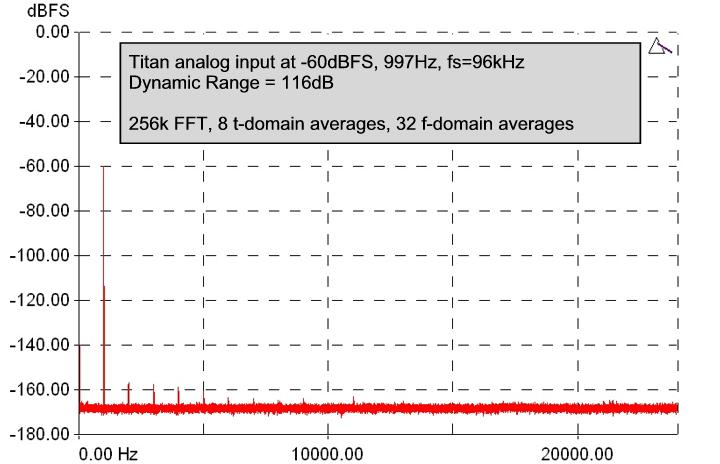
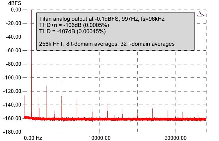
68 1.62
69 Except where otherwise stated, audio performance data are typical, RMS, unweighted, 20Hz..20kHz figures, measured at 997Hz, using fs=96khz and '+4dBu' sensitivity settings. In keeping with our policy of continual development, specifications are subject to amendment without notice. E&OE. All Trade Marks acknowledged. 1.63
70 CleverClox 45 Clock Out control 35 Clocking 45 Connectors 29, 31, 54 Control Panel app 34, 39 Cooling 32 Core Audio 12, 39 Index ---20dB mic pads 37 -D x clock 29 -AADAT inputs 23 ADAT mode 35, 37, 38, 39 ADAT mode control 35 ADAT outputs 25 ADM 26 AES11 24, 26, 29 AES3 inputs 23 AES3 outputs 25 Aggregation 19 Analogue inputs 22, 37 Analogue interconnections 52 Analogue outputs 24, 38 Architecture 22 ASIO 14, 39 ASIO buffer 35 ASIO Direct Monitoring 26 Assignable level control 27, 28, 38 Async (ASNC) indicator 23, 37 -BBalanced connections Base control 35 Baseclock 29 Block diagram 22 Breakout cables 54 Brightness, front panel Buffer control 35 Buffer size 35, 44 -CCable impedance Cabling , Delay 26 Device aggregation 19 Device Manager 34 DI inputs 22 DI synchronization 24 Digital inputs 23, 37 Digital interconnections 54 Digital outputs 25, 38 Dither 26, 47 DO synchronization 26 Drift Correction check-box 19 Driver updates 19 Drivers 39 -EEarthing 52, 54 Ethernet interface 29 -FFaders 26 Features 6 Firmware updates 19 Firmware version 35 Foldback mixers 39 FP Meters control 35 Front panel 29 Fuse locations and ratings 32 -GGetting started, Mac 10 Getting started, Windows Glitches 44 Grounding 52, 54 10
71 -HHeadphone outputs 27, 38 Help button 35 High-pass filter 23, 37 Host indicator 28, 29 Host interface 29 HPF 23, 37 Hum loops 52, 54 -IIdentify button 35 Impact filter 23 Input controls 37 Input mode 22 Input selection indicators 29 Inputs tab 37 Inputs, ADAT 23 Inputs, analogue 22, 28 Inputs, digital 23, 28 Inputs, S/PDIF 23, 24 Installation, Mac 12 Installation, Windows 14 Instrument inputs 22, 37 Interconnections 52, 54 Interference 52, 54 -JJitter 45, 54 JTEST 45 -LLatency 26, 44 LED brightness 35 LED indicators 29 Level control 27 Level meters 28 Line inputs 22, 37 Line outputs 38 Load button 35 Local sync 32 Lock button 38 Low-latency mixers 39 -MMac 10, 12, 34 Manual 7 Master indicator 29 MDIO expansion slot 27, 28, 29, 31 Meter panel 29 Meters 28 Mic input pads 22 Mic inputs 22, 37 Mic pads 22, 37 Microphone preamplifiers 22 Mixer controls 39 Mixers 26, 38, 39 Monitor control 27 MS matrix 23, 37 Multiple units 19 Mute button 26, 27, 38 -NNoise-shaping 26, 47 -O 7 Operation of multiple units 19 Operation without a computer 32 OS X 10, 12, 39 OS X versions 7, 10, 12 Output controls 38 Output ganging 24, 26, 27 Output mixers 26 Output mute 27 Outputs tab 38 Outputs, ADAT 25 Outputs, AES3 25 Outputs, analogue 24, 28 Outputs, digital 25, 28 Outputs, headphone 27 Outputs, S/PDIF 25 Over-dubbing 26, 44 Overkiller 23, 28, 37 Overload indicators 28 Overview 6
72 Stability 44 Stand-alone operation 26, 32 Switched-mode power supplies Sync Source control 35 Synchronization 24, 26, 29 Synchronization source 32 System requirements 7 -PPan pots 26 PC 10, 14 Phantom power 22, 37 Phase-reverse 37 Phono cartridges 23, 52 Prism Sound, CleverClox 45 Prism Sound, SNS (Super Noise-Shaping) 47 -QQuick start guide, Mac 10 Quick start guide, Windows 10 -RRack mounting kit 32 Rear panel 31 Re-dithering 26, 47 Ref Sync 24, 26, 29, 45 Reference sync 24, 26, 29, 45 RIAA de-emphasis filter 23, 37, 52 Routing matrix 26, 27 Rubber feet 32 -SS/PDIF input 24 S/PDIF inputs 23 S/PDIF output 25 S/PDIF outputs 25 Sample rate 54 Sample Rate control 35 Sample-rate converter 24, 25 Sampling jitter 45 Save button 35 Serial number 35 SNS (Super Noise-Shaping) 26, 47 SNS Logo, use of 47 Software 34 Software updates 19 Software version 19 Solo 26 Specifications 58 SRC 24, 25, 29 SRC control 35 26, 52, 54 -TTechnical topics 44 Titan Control Panel app TOSLINK 54 TPDF 26, UUnbalanced connections 22, 24 Unit settings 35 Unlocked (ULOK) indicator 23, 37 Updating software 19 -VVerifile 29, 38, 40, 50 Verifile Checker app 35, 40 Verifile enable 35 Vinyl decks 23, 52 Volume control 27 -WWDM audio 14, 39 Windows 10, 14, 34, 39 Windows versions 7, 10, 14 Wordclock 24, 26, 29, 45 Word-length 26, 47
73
74
Orpheus. Operation Manual. by Ian Dennis
 Orpheus by Ian Dennis This manual is also available as 'on-line help' from the Orpheus Control Panel applet. You can access the on-line help from the 'Help' button in the top right-hand corner of the applet.
Tactus Stage Mixing Interface
 Tactus Stage Mixing Interface Operating Manual www.peaveycommercialaudio.com FCC/ICES Compliancy Statement This device complies with Part 15 of the FCC rules and Industry Canada license-exempt RSS Standard(s).
MDIO-PTHDX Module. Operation Manual
 MDIO-PTHDX Module Operation Manual Table of Contents General Information... 5 Introduction... 7 Terminology... 8 Quick Start Guide... 9 Connection Diagrams... 10 Multiple Stacks... 11 Combining with Pro
Dream. Prism. Operation Manual
 Prism Dream Operation Manual st Issue 2.01 21 January 1998 Prism Media Products Limited William James House Cowley Road Cambridge CB4 4WX UK Phone: +44-(0)1223-424988 Fax: +44-(0)1223-425023 Email: support@prismsound.com
User Manual. Neve Channel Strip Issue 2. !!!Please read includes important safety instructions!!!
 User Manual Neve 8801 Channel Strip 527 358 Issue 2!!!Please read includes important safety instructions!!! 2007 AMS Neve Ltd own the copyright of all information and drawings contained in this manual
USB AUDIO INTERFACE I T
 USB AUDIO INTERFACE EN DE FR ES IT JA Contents Introduction...3 Contents in this Operation Manual... 3 Features... 3 Panel Controls and Terminals (Details)...4 Rear Panel... 4 Front Panel... 6 Panel Controls
S1 Digital/Analogue Radio Broadcast Mixer
 S1 Digital/Analogue Radio Broadcast Mixer September 2009 www.sonifex.co.uk t: +44 (0)1933 650 700 f: +44 (0)1933 650 726 sales@sonifex.co.uk S1 Radio Digital/Analogue Broadcast Mixer Radio Broadcast Mixer
S1 Digital/Analogue Radio Broadcast Mixer September 2009
 S1 Digital/Analogue Radio Broadcast Mixer September 2009 www.sonifex.co.uk t: +44 (0)1933 650 700 f: +44 (0)1933 650 726 sales@sonifex.co.uk S1 Radio Digital/Analogue Broadcast Mixer Radio Broadcast Mixer
There is a button to select either the AES/EBU or S/PDIF input for the D/A converter, which is located on the rear panel.
 4 RB-DAC1 Digital to Analogue Converter Introduction Fig 4-1: RB-DAC1 Front Panel Using 24 bit, 96kHz capable devices, the RB-DAC1 Digital to Analogue Converter is a 1U rack-mount which produces a stereo
CDM10: Channel USB Mixer. Item ref: UK User Manual
 CDM10:4 19 4 Channel USB Mixer Item ref: 171.135UK User Manual Caution: Please read this manual carefully before operating Damage caused by misuse is not covered by the warranty Introduction Thank you
2
 328 328 USER GUIDE NB Before you go any further, please read this first page as it will tell you all you need to know about starting off with the Spirit Digital 328 From all of us to you Thank you for
ULN-8 Quick Start Guide
 Metric Halo $Revision: 1671 $ Publication date $Date: 2012-7-21 12:42:12-0400 (Mon, 21 Jul 2012) $ Copyright 2012 Metric Halo Table of Contents 1.... 5 Prepare the unit for use... 5 Connect the ULN-8 to
Recording to Tape (Analogue or Digital)...10
...10") c o n t e n t s DUAL MIC-PRE Green Dual Mic Pre (introduction).............................4 Section (i): Setting Up Power Connections...........................................4 Power Supply................................................5
c o n t e n t s DUAL MIC-PRE Green Dual Mic Pre (introduction).............................4 Section (i): Setting Up Power Connections...........................................4 Power Supply................................................5
Quick Start Guide. Soundcraft Si Series Quick Start Guide Issue 1010
 Quick Start Guide Soundcraft Si Series Quick Start Guide Issue 1010 Page 1 INTRODUCTION IMPORTANT Please read this manual carefully before using your mixer for the first time. Firstly, thanks for choosing
spider a bit of information
 spider a bit of information Please read this before connecting power to the unit. There are important things about the power cable and cooling that must be done to allow for long life and reliable operation.
TL AUDIO M4 TUBE CONSOLE
 TL AUDIO M4 TUBE CONSOLE USER MANUAL TL AUDIO M4 TUBE CONSOLE M4 INTRODUCTION... 3 M4 MIXER TECHNICAL SPECIFICATION... 4 Mic Input:... 4 Line Input:... 4 Phase Rev:... 4 High Pass Filter:... 4 Frequency
DSA-1. The Prism Sound DSA-1 is a hand-held AES/EBU Signal Analyzer and Generator.
 DSA-1 The Prism Sound DSA-1 is a hand-held AES/EBU Signal Analyzer and Generator. The DSA-1 is an invaluable trouble-shooting tool for digital audio equipment and installations. It is unique as a handportable,
M A S T E R S E C T I O N. User Manual
 M A S T E R S E C T I O N User Manual Version 1.02: July 2007 Contents. Safety Information.... 3 Welcome.... 4 Connections.... 5 A Basic Set-up 5 Setting Up.... 7 Adjusting Input Levels 7 Taking Account
LIO-8 Quick Start Guide
 Metric Halo $Revision: 1051 $ Publication date $Date: 2011-08-08 12:42:12-0400 (Mon, 08 Jun 2011) $ Copyright 2010 Metric Halo Table of Contents 1.... 5 Prepare the unit for use... 5 Connect the LIO-8
ENG-44 Field Portable Audio Mixer. Operator s Manual. SignVideo SE Gideon Street - Portland, Oregon
 Field Portable Audio Mixer Operator s Manual SignVideo - 1226 SE Gideon Street - Portland, Oregon 97202 503.236.0000 www.signvideo.com Safety Warning Protect your ears. Always turn down the headphone volume
10 in 10 out PCI Digital Recording System with S/PDIF. User Guide
 10 in 10 out PCI Digital Recording System with S/PDIF User Guide Table of Contents Introduction.............................. 3 What s in the Box?.......................... 3 About the Delta 1010 Digital
Neve 8801 Channel Strip User Manual
 Neve 8801 Channel Strip User Manual 527-358 Issue 7.3 The 8801 is a combined Mic / Line / Instrument Preamp, with Dynamics processing, EQ and Insert point. The Audio Router function provides a user configurable
LavryBlack Series Model AD11 Stereo Analog to Digital Converter With Microphone Preamplifier
 LavryBlack Series Model AD11 Stereo Analog to Digital Converter With Microphone Preamplifier Lavry Engineering, Inc. P.O. Box 4602 Rolling Bay, WA 98061 http://lavryengineering.com email: techsupport@lavryengineering.com
DM1624, DM1612, DM812
 Installation Guide Hardware and Software DM Series Digital Processors models DM1624, DM1612, DM812 LECTROSONICS, INC. 1 Installation Specific Information Only This guide covers only installation related
ADA-8 Multi-channel A/D D/A Converter. Operation Manual
 ADA-8 Multi-channel A/D D/A Converter Operation Manual Operation Manual Revision History Rev Date Author Comments 1.00 11 th January 2002 Ian Dennis Initial release with 1.22 firmware Support Contacts
AUDIOFIRE 2 AUDIOFIRE 4 AUDIOFIRE 8 AUDIOFIRE 12
 AUDIOFIRE 2 AUDIOFIRE 4 AUDIOFIRE 8 AUDIOFIRE 12 Owner s Manual Version 2.0 for Windows Important Safety Instructions 1. Read Instructions Be sure to read all of the safety and operating instructions before
MadiXtreme / Alpha-Link XLogic I/O system for PC and Mac Setup Guide V1.0 XLogic. This is SSL.
 www.solidstatelogic.com MadiXtreme / Alpha-Link XLogic I/O system for PC and Mac Setup Guide V1.0 XLogic. This is SSL. Document History 82BSA101A March 2012 V1.0 Initial Release Contents Introduction 1
MASTERING DIGITAL TO ANALOG USER MANUAL. VER.7/April Use ver.5 manual for earlier units (without toslink)
") MASTERING DIGITAL TO ANALOG CONVERTER USER MANUAL VER.7/April 2007 Use ver.5 manual for earlier units (without toslink) Quick Start.3 Introduction.....4 This manual may be updated Download the newest version
MASTERING DIGITAL TO ANALOG CONVERTER USER MANUAL VER.7/April 2007 Use ver.5 manual for earlier units (without toslink) Quick Start.3 Introduction.....4 This manual may be updated Download the newest version
T L Audio. User Manual C1 VALVE COMPRESSOR. Tony Larking Professional Sales Limited, Letchworth, England.
 T L Audio User Manual C1 VALVE COMPRESSOR Tony Larking Professional Sales Limited, Letchworth, England. Tel: 01462 490600. International +44 1462 490600. Fax: 01462 490700. International +44 1462 490700.
SCM820 Digital IntelliMix Automatic Mixer SEAMLESS MIXING. ADVANCED CONTROL.
 SCM820 Digital IntelliMix Automatic Mixer SEAMLESS MIXING. ADVANCED CONTROL. SCM820 Digital IntelliMix Automatic Mixer The SCM820 is the flagship Shure digital automatic mixer for seamless, natural-sounding
System Interface Unit SIU-100/100T
 System Interface Unit /100T Since its introduction, the Digital Mixer has opened up an entirely new set of opportunities for affordable PA and sound-recording applications. Recognizing the ever-increasing
M-16DX 16-Channel Digital Mixer
 M-6DX 6-Channel Digital Mixer Workshop Getting Started with the M-6DX 007 Roland Corporation U.S. All rights reserved. No part of this publication may be reproduced in any form without the written permission
FF DUAL FORMAT DJ MIXER USERS MANUAL
 FF - 4000 DUAL FORMAT DJ MIXER USERS MANUAL FF - 4000 INTRODUCTION The features and layout of the FF-4000 were determined in collaboration with leading loudspeaker manufacturers Funktion One, who canvassed
Connevans.info. DeafEquipment.co.uk. This product may be purchased from Connevans Limited secure online store at
 Connevans.info Solutions to improve the quality of life Offering you choice Helping you choose This product may be purchased from Connevans Limited secure online store at www.deafequipment.co.uk DeafEquipment.co.uk
X-Series Expansion Cards. X-Video Card
 X-Series Expansion Cards X-Video Card User s Guide v1.0 - February 2006 Warnings FCC warning This equipment has been tested and found to comply with the limits for a Class A digital device, pursuant to
ProFire 610. English. User Guide
 English User Guide User Guide Introduction............................................................ 3 What s in the Box........................................................ 3 Your ProFire 610 package
FCC Compliance Statement
 FCC Compliance Statement This device complies with part 15 of the FCC Rules. Operation is subject to the following two conditions: 1. This device may not cause harmful interference, and 2. This device
MX 3BT NF TK MAIN 2TK 2TK BT
 MX.3BT MX 3BT BT MAIN NF03852-1.1 The mains plug or an appliance coupler is used as the disconnect device, the disconnect device shall remain readily operable. 1. INTRODUCTION...4 2. FEATURES...4 3. INSTRUCTION...4
Installation and Users Guide Addendum. Software Mixer Reference and Application. Macintosh OSX Version
 Installation and Users Guide Addendum Software Mixer eference and Application Macintosh OSX Version ynx Studio Technology Inc. www.lynxstudio.com support@lynxstudio.com Copyright 2004, All ights eserved,
2012 AETA Audio Systems C 1
 212 AETA Audio Systems www.aeta-audio.com 12 55 55-C 1 OK, So smart people don t read manuals but MIXY is smart too. Don t be fooled by her simple looks, there s a great deal more to her than meets the
USER GUIDE MULTI-CHANNEL STEREO MIXER S MIX 4M2S UD
 USER GUIDE MULTI-CHANNEL STEREO MIXER S MIX 4M2S UD FEATURES 4 mono input channels and 2 stereo input channels. Frequency EQ on each input channel. Low-noise mic pre-amp on microphone inputs. Low cut filter
S0 Radio Broadcasting Mixer. June catalogue. Manufacturers of audio & video products for radio & TV broadcasters
 S0 Radio Broadcasting Mixer June 2012 catalogue Manufacturers of audio & video products for radio & TV broadcasters S0 Radio Broadcasting Mixer A simple radio mixer for novice and professional users The
Personal Q Guide for VENUE Systems
 Personal Q Guide for VENUE Systems Version 1.0 Digidesign 2001 Junipero Serra Boulevard Daly City, CA 940-3886 USA tel: 650 731 6300 fax: 650 731 6399 Technical Support (USA) tel: 650 731 6100 fax: 650
Mastering Analog to Digital / Digital to Analog Converter. User Manual Including February 2017 Version 8 Firmware and Feature Update
 Mastering Analog to Digital / Digital to Analog Converter User Manual Including February 2017 Version 8 Firmware and Feature Update Lynx Studio Technology, Inc. www.lynxstudio.com support@lynxstudio.com
Apogee Ensemble. Thunderbolt Audio Interface
 Apogee Ensemble Thunderbolt Audio Interface User s Guide Fall 2014 Contents Overview!... 5 Introduction!... 5 Features!... 5 Package Contents!... 6 Ensemble Thunderbolt Panel Tour!... 7 Front Panel!...
IOS. Table of Contents
 Table of Contents Introduction...4 1. Getting Started...5 1.1 System Requirements...5 1.2 Registration...5 1.3 Software Installation...6 1.4 Licenses...6 2. Hardware...7 3. Suggested Uses And Configurations...9
Technical Specifications
 INSTALLATION SHEET AND OPERATORS MANUAL General Description: The is a mixer/preamplifier that includes 6 channels that each include a microphone input at screw terminals and an aux input at an RCA jack.
1073DPA and 1073DPD Mic Pre- Amplifier
 AMS NEVE 1073DPA and 1073DPD Mic Pre- Amplifier 527-349 Issue 2 2005 AMS Neve plc own the copyright of all information and drawings contained in this manual which are not to be copied or reproduced by
CM4-BT. Compact Mixer with Bluetooth UK User Manual
 CM4-BT Compact Mixer with Bluetooth 170.804UK User Manual Caution: Please read this manual carefully before operating Damage caused by misuse is not covered by the warranty Introduction: Thank you for
S MiX 2M2S UF. S MiX 2M2S F
 USER guide MULTI-CHANNEL STEREO MIXER S MiX 2M2S UF S MiX 2M2S F FEATURES 2 stereo input channels and 2 mono input channels. 2-band frequency EQ for each input channel. Low-noise mic pre-amp on microphone
LavryBlack Series Model AD10 Analog to Digital Converter
 LavryBlack Series Model AD10 Analog to Digital Converter Lavry Engineering, Inc. P.O. Box 4602 Rolling Bay, WA 98061 http://lavryengineering.com email: techsupport@lavryengineering.com Rev 1.20 January
DRAWMER D-Clock DMS-2 WORD CLOCK MEASUREMENT AND DISTRIBUTION AMPLIFIER CONTENTS
 DRAWMER D-Clock DMS-2 WORD CLOCK MEASUREMENT AND DISTRIBUTION AMPLIFIER CONTENTS Warranty........................................................... 2 Safety Consideration.................................................
OPERATIONS MANUAL FOR EDISON PROFESSIONAL Professional ABS Molded Loudspeaker M4000
 M4000 Introduction: Congratulations on your purchase of an M-4000 powered loudspeaker, engineered and manufactured by BriteLite Enterprises. The M-4000 includes a high-output compression driver, and 15
The Dangerous Music D-Box user s operating guide
 The Dangerous Music D-Box user s operating guide Thank you for choosing products from the exciting line of Dangerous Music recording equipment. Many years of dependable and trouble-free service can be
PLAYMATE PROFESSIONAL STEREO 19 MIXER, USB/SD CARD AND BLUETOOTH PLAYER. User Guide and Reference Manual. page 1
 PLAYMATE PROFESSIONAL STEREO 19 MIXER, USB/SD CARD AND BLUETOOTH PLAYER User Guide and Reference Manual page 1 INTRODUCTION Congratulations and thank you for purchasing the NewHank Playmate mixer. This
SIGNAL PROCESSOR. Operation Manual
 SIGNAL PROCESSOR Operation Manual Using the PDF manual From the Contents on page 2, click on the desired topic to automatically jump to the corresponding page. Click on a link in this manual to jump to
User Manual U-CONTROL UCA222. Ultra-Low Latency 2 In/2 Out USB Audio Interface with Digital Output
 User Manual U-CONTROL UCA222 Ultra-Low Latency 2 In/2 Out USB Audio Interface with Digital Output 2 U-CONTROL UCA222 User Manual Table of Contents Thank you...2 Important Safety Instructions...3 LEGAL
Element 78 MPE-200. by Summit Audio. Guide To Operations. for software version 1.23
 Element 78 MPE-200 by Summit Audio Guide To Operations for software version 1.23 TABLE OF CONTENTS IMPORTANT SAFETY AND GROUNDING INSTRUCTIONS COVER 1. UNPACKING AND CONNECTING...3 AUDIO CONNECTIONS...4
AT-MX351a SmartMixer. Automatic Mixer. Installation and Operation. Output Level Gain 1 Gain 2 Gain 3 Gain 4 Aux In Master Monitor. Priority Pre-select
 AT-MX351a SmartMixer Automatic Mixer AUTOMATIC MIXER AT-MX351a Output Level Gain 1 Gain 2 Gain 3 Gain 4 Aux In Master Monitor -20-10 -6-3 0 +3 +6 Priority Pre-select Power Selected Channel 1 2 3 4 MANUAL
CHAPTER 3 AUDIO MIXER DIGITAL AUDIO PRODUCTION [IP3038PA]
![CHAPTER 3 AUDIO MIXER DIGITAL AUDIO PRODUCTION [IP3038PA]](/thumbs/73/68858919.jpg "CHAPTER 3 AUDIO MIXER DIGITAL AUDIO PRODUCTION [IP3038PA]") CHAPTER 3 AUDIO MIXER DIGITAL AUDIO PRODUCTION [IP3038PA] Learning Objectives By the end of this chapter, students should be able to: 1 State the function of the audio mixer in the sound studio. 2 Explain
CHAPTER 3 AUDIO MIXER DIGITAL AUDIO PRODUCTION [IP3038PA] Learning Objectives By the end of this chapter, students should be able to: 1 State the function of the audio mixer in the sound studio. 2 Explain
User Guide. FFFA WORD CLOCK SECONDARY PRIMARY NETWORK PRIMARY CLOCK SOURCE WORD CLOCK. SAMPLE RATE 44.
 User Guide NETWORK PRIMARY SAMPLE RATE 44.1 khz 2 CLOCK SOURCE WORD CLOCK DARS SECONDARY 48 khz 4 1-2 3-4 5-6 7-8 9-10 11-12 13-14 15-16 PUT 1-2 POWER LOCKED PULL UP/DOWN PUT 9-10 TERNAL PSU A PSU B NETWORK
User Instructions. 16 SCB Sync Station.
 User Instructions 16 SCB Sync Station Contents Overview... 1 Specifications... 1 Compliance and approvals... 2 Safety instructions... 3 Set up... 4 How to charge multiple devices... 4 How to synchronize
Headphones Boxes Sample rate converter Auto level takers Interboxes Digital Tone generator Digital headphones
 BLACK BOXES INDEX PAGE 2 3,4 5,6 7,8 9,10 11,12 TITLE Headphones Boxes Sample rate converter Auto level takers Interboxes Digital Tone generator Digital headphones The BCD Audio Black-box range provides
SIGNAL PROCESSOR. Operation Manual
 SIGNAL PROCESSOR Operation Manual Using the PDF manual From the Contents on page 2, click on the desired topic to automatically jump to the corresponding page. Click on a link in this manual to jump to
USER MANUAL MX102 & MX1202
 USER MANUAL MX102 & MX1202 WWW.PULSE-AUDIO.CO.UK 1 SAVE THESE SAFETY INSTRUCTIONS Thank you for purchasing our product. To assure the optimum performance, please read this manual carefully and keep it
DIGITAL SPEAKER MANAGEMENT UK
 DSM2-6mkII DIGITAL SPEAKER MANAGEMENT 170.659UK Features 96kHz sampling frequency, 32-bit A/D and D/A converter, 24-bit DSP processor Input channel: 6-band parametric EQ, Delay, Polarity Output channel:
DA IN 1-OUT LINE DRIVER WITH EQUALIZATION + AUDIO USER S GUIDE
 MANUAL PART NUMBER: 400-0430-001 1-IN 1-OUT LINE DRIVER WITH UALIZATION + AUDIO USER S GUIDE TABLE OF CONTENTS Page PRECAUTIONS / SAFETY WARNINGS... 2 GENERAL...2 GUIDELINES FOR RACK-MOUNTING...2 INSTALLATION...2
2-Port Hub Type 1 2-Port Hub Type 3 Unshielded 2-Port Hub Type 3 Shielded
 Type 1 Type 3 Unshielded Type 3 Shielded SEPTEMBER 1994 LT7000A LT7001A LT7002A 1 2 R I N G Type 1 R I N G 1 2 Type 3 R I N G 1 2 Type 3 CUSTOMER SUPPORT INFORMATION Order toll-free in the U.S. 24 hours,
CMX-DSP Compact Mixers
 CMX-DSP Compact Mixers CMX4-DSP, CMX8-DSP, CMX12-DSP Introduction Thank you for choosing a Pulse CMX-DSP series mixer. This product has been designed to offer reliable, high quality mixing for stage and/or
Kramer Electronics, Ltd. USER MANUAL. Models: 6410N, Digital to Analog Audio Converter 6420N, Analog to Digital Audio Converter
 Kramer Electronics, Ltd. USER MANUAL Models: 6410N, Digital to Analog Audio Converter 6420N, Analog to Digital Audio Converter Contents Contents 1 Introduction 1 2 Getting Started 1 2.1 Quick Start 1 3
CR-6 MIXER USER MANUAL ENGLISH. Order Code: MIXE01
 CR-6 MIXER P R O F E S S I O N A L 1 9 R A C K M I X E R Order Code: MIXE01 w w w. p r o l i g h t. c o. u k USER MANUAL ENGLISH WARNING FOR YOUR OWN SAFETY, PLEASE READ THIS USER MANUAL CAREFULLY BEFORE
Sync Genlock JULY 1993 AC083A. Sync Genlock
 JULY 1993 AC083A Sync Genlock Sync Genlock SC H PHASE SC 0 SC 180 SLOW LOCK FAST LOCK DISABLE ENABLE ENABLE POWER BURST CUSTOMER SUPPORT INFORMATION Order toll-free in the U.S. 24 hours, 7 A.M. Monday
MONOPRICE. Blackbird 4K HDBaseT Extender Kit. User's Manual P/N 21792
 MONOPRICE Blackbird 4K HDBaseT Extender Kit P/N 21792 User's Manual SAFETY WARNINGS AND GUIDELINES Please read this entire manual before using this device, paying extra attention to these safety warnings
3124mb+ All Discrete 4 Channel Mic/Instrument Preamplifier with Stereo Mixer Operator s Manual
 3124mb+ All Discrete 4 Channel Mic/Instrument Preamplifier with Stereo Mixer Operator s Manual Written by Carl J Houde 2015 Table of Contents 1.0 Introduction... 3 2.0 Overview... 4 2.1 3124mb+ Features
Reflecta Super 8 Scanner. User Manual
 Reflecta Super 8 Scanner User Manual 1 FEDERAL COMMUNICATIONS COMMISSION (FCC) STATEMENT This Equipment has been tested and found to comply with the limits for a class B digital device, pursuant to Part
LX20 OPERATORS MANUAL
 LX20 OPERATORS MANUAL CONTENTS SAFETY CONSIDERATIONS page 1 INSTALLATION page 2 INTRODUCTION page 2 FIRST TIME USER page 3 SYSTEM OPERATING LEVELS page 3 FRONT & REAR PANEL LAYOUT page 4 OPERATION page
PHOENIX AUDIO. Owner s Manual
 PHOENIX AUDIO Costa Mesa CA 92262 USA Telephone +1 866 302 1091 Email :sales@phoenixaudio.net Owner s Manual Firstly, let us congratulate you on your purchase of the Ascent-Two Microphone Pre- Amplifier.
Neve :2 Summing Mixer User Manual
 Neve 8816 16:2 Summing Mixer User Manual 527-361 Issue 5 AMS NEVE Billington Road Burnley Lancs BB11 5UB England Phone +44 (0)1282 457011 Fax: +44 (0)1282 417282 info@ams-neve.com www.ams-neve.com www.neve.eu
Lynx e22/e44. User Manual Table of Contents
 4/11/2016 Lynx e22/e44 User Manual Table of Contents 1 Introduction...4 1.1 Overview...4 1.2 Features...5 2 Before you begin...6 2.1 In the box...6 2.2 Operational requirements...6 2.2.1 Windows... 7 2.2.2
X-Panda User s Guide
 X-Panda User s Guide This documentation is intended to be read along side the X-Panda Installation Guide which is available for download from our website www.solidstatelogic.com 82BXEM01A Contents Introduction
AVerMedia DarkCrystal HD Capture SDK II C729. English. Quick Guide
 AVerMedia DarkCrystal HD Capture SDK II C729 English Quick Guide FCC NOTICE (Class B) This device complies with Part 15 of the FCC Rules. Operation is subject to the following two conditions: (1) this
USER MANUAL. 22" Class Slim HD Widescreen Monitor L215DS
 USER MANUAL 22" Class Slim HD Widescreen Monitor L215DS TABLE OF CONTENTS 1 Getting Started Package Includes Installation 2 Control Panel / Back Panel Control Panel Back Panel 3 On Screen Display 4 Technical
SOUNDCRAFT. User Guide
 SOUNDCRAFT User Guide Harman International Industries Ltd. 1996,1997 All rights reserved Parts of the design of this product may be protected by worldwide patents. Part No. ZM0143 Issue 3 Soundcraft is
VNS2200 Amplifier & Controller Installation Guide
 VNS2200 Amplifier & Controller Installation Guide VNS2200 Amplifier & Controller Installation 1. Determine the installation location for the VNS2200 device. Consider the following when determining the
X-Four console. description. features. sound fundamentals. built to defy murphy s law. wide range of configurations
 X-Four console description If your application requires all the features and performance of a thoroughly-professional mixing console, but presents severe spacerestrictions, then the Crest Audio X-Four
Instruction Manual By Digital & Analog
 FEMTO Instruction Manual By Digital & Analog www.calyxaudio.com 1 Thank you for purchasing FEMTO Music is the most important messenger of human emotion as well as a meaning of its expression since human
TECHNICAL MANUAL. Cheetah VIDEO MATRIX ROUTERS 3G VIDEO INPUT CARD WITH AUDIO DE-EMBEDDING AND 3G VIDEO OUTPUT CARD WITH AUDIO EMBEDDING
 TECHNICAL MANUAL Cheetah VIDEO MATRIX ROUTERS 3G VIDEO INPUT CARD WITH AUDIO DE-EMBEDDING AND 3G VIDEO OUTPUT CARD WITH AUDIO EMBEDDING Publication: 81-9059-0658-0, Rev. A August, 2009 Thank You!! for
OWNERS MANUAL LUNATEC V3 MICROPHONE PREAMPLIFIER AND A/D CONVERTER
 OWNERS MANUAL LUNATEC V3 MICROPHONE PREAMPLIFIER AND A/D CONVERTER LUNATEC 35 +48 35 +48 30 40 30 40 0 25 45 25 45 3 192 1 1 6 176.4 20 50 20 50 9 96 12 PEAK 88.2 55 55 RESET 48 10 60 2 10 60 2 21 44.1
P-2 Installing the monitor (continued) Carry out as necessary
 Carry out as necessary") P-2 Installing the monitor (continued) Carry out as necessary Using the monitor without the bezel MDT552S satisfies the UL requirements as long as it is used with the bezel attached. When using the monitor
P-2 Installing the monitor (continued) Carry out as necessary Using the monitor without the bezel MDT552S satisfies the UL requirements as long as it is used with the bezel attached. When using the monitor
$2495. Ensemble 30x34 Thunderbolt Audio Interface HIGHLIGHTS. For more information, visit apogeedigital.com/products/ensemble
 Ensemble 30x34 Thunderbolt Audio Interface $2495 The new Apogee Ensemble is the first Thunderbolt 2 audio interface to offer superior sound quality, the lowest latency performance and the most comprehensive
DMS-6 DUAL REDUNDANT WORD CLOCK DISTRIBUTION AMPLIFIER CONTENTS
 DRAWMER D-Clock-R DMS-6 DUAL REDUNDANT WORD CLOCK DISTRIBUTION AMPLIFIER CONTENTS Warranty........................................................... 2 Safety Consideration.................................................
USER MANUAL GOLDMUND MIMESIS 32.5 Universal Acoustic Processor
 USER MANUAL GOLDMUND MIMESIS 32.5 Universal Acoustic Processor Congratulations. Thank you for purchasing the Goldmund MIMESIS 32.5 UNIVERSAL ACOUSTIC PROCESSOR. You have acquired the best multi-usage acoustic
User Guide FA
 User Guide ON FA9096-06 www.focusrite.com CONTENTS About this User Guide...3 Box Contents................................................................3 INTRODUCTION... 4 INSTALLATION GUIDE... 5 RedNet
MCM-20.4 PRELIMINARY USER GUIDE v1.1
 MCM-20.4 PRELIMINARY USER GUIDE v1.1 2017 All the documentation included in this manual is copyrighted by Heritage Audio S.L. All rights are reserved. No part of this manual may be reproduced, copied,
D-2000 SERIES DIGITAL MIXING SYSTEM
 D-2000 SERIES DIGITAL MIXING SYSTEM Integrating high-performance mixing, matrixing and processing functions to meet a wide scope of sound reinforcement applications Expandable a operation, a system contr
 Register your product and get support at www.philips.com/welcome SWW1890 User manual Contents 1 Important 4 Safety 4 English 2 Your Philips Wireless HD Net Connect 5 What is in the box 5 3 Overview 6
HDMI 4x2 Matrix Switch 1.3b
 HDMI 4x2 Matrix Switch 1.3b Quick Start Guide English LINDY No. 38042 www.lindy.com LINDY ELECTRONICS LIMITED & LINDY-ELEKTRONIK GMBH - FIRST EDITION (March 2009) 1. Introduction Thank you for purchasing
Reference Guide 2014 ZOOM CORPORATION. Copying or reprinting this manual in part or in whole without permission is prohibited.
 Reference Guide 2014 ZOOM CORPORATION Copying or reprinting this manual in part or in whole without permission is prohibited. Introduction is a mixer application designed specifically for the. Using a
Cat s Eye edta-164 HDTV Tuner Card
 Cat s Eye edta-164 HDTV Tuner Card Installation Guide Version 1.0 VBox Communications Ltd. www.vboxcomm.com Copyright 2006, VBox Communications Ltd. All rights reserved. No part of this publication may
ANALOG RADIO MIXER. Flexible. Affordable. Built To Last.
 ANALOG RADIO MIXER Flexible. Affordable. Built To Last. Audioarts AIR-4 A N A L O G R A D I O M I X E R At Audioarts, value engineering is straightforward: Define the features our customers require. Design