SHENZHEN H&Y TECHNOLOGY CO., LTD
|
|
|
- Camilla Morrison
- 6 years ago
- Views:
Transcription
1 Chapter I Model801, Model802 Functions and Features 1. Completely Compatible with the Seventh Generation Control System The eighth generation is developed based on the seventh. Compared with the seventh, the eighth has all the functions of the seventh. Moreover, the eighth is more functional, more powerful, more stable and more reliable. 2. Supporting 210 colors The seventh supports 28 colors: 28*28*28= kinds of colors. The eighth supports 210 colors: 210*210*210= kinds of colors. It needs to work with our video processors using the 30 bits TTL. So the coloring number of the eighth is 64 times as much as that of the seventh. 3. The intelligent connecting function Without resetting the configurations, the receiving cards (including spare ones) of the same LED display/cabinet can be randomly exchanged or replaced, for they will automatically recognize the showing area and content they are responsible for. 4. The intelligent supervision function In each receiving card, there is a temperature sensor and four fan-power-output-ports. The speed of the fans is under wise controlled according to the warming value of temperature set by users. 5. Company Logo Showing If the power of the sending card is not turned on, the monitor the PC will automatically show the preset company picture. The pixel of the picture will be 128*128, the coloring number 16K. 6. Supporting more scan mode The seventh supports 1, 2, 4, 8, 16 scan mode, the eighth supports 1, 2, 3, 4, 5, 6, 7, 8, 9. 10, 11, 12, 13, 14, 15, 16 scan mode. 7. Supporting more modules The seventh supports modules with the width: 2pixels, 4 pixels, 8 pixels, 16 pixels, 32 pixels, 64 pixels. The eighth supports all the modules with width within 64 pixels. That is from 1 pixel to 64 pixels. 8. Supporting cut-up function Each receiving card max supports 1024 pieces cutup, for non-conventional type display or text display use. 9. supporting empty pixel insert The eighth can be set to insert one or more empty pixels every X pixels. This function is applying in non-conversional type display. 10. Supporting PWM driver chip Need to use particular driver chip Make the display effect going perfect 11. Supporting hardware pixel by pixel correction Need to use particular driver chip. By changing the current for the LED, adjust the 27
2 color, wave and brightness of the LED. Make the effect of display pixel by pixel correction better. 12. Supporting pixel supervision function Need to use particular driver chip Dynamically check the bad pixels on the display. 13. Giga Technology Veritable Giga technology. One sending card can support the max pixels: Model701: 1280*1024; model702: 2048*640; two cards are cascaded: 2048*1152. Single network cable supports the max pixels: model701: 1024*640, 1280*512; model702: 1600*400, 2048* Pixel by Pixel Correction and Unit box by Unit box Correction Function Pixel by pixel correction supports four kinds of correction modes: single pixel, 2*2pixels, 4*4 pixels, 8*8 pixels; and the max correction is 6144 pixels/module, and brightness 256 levels for red, green, blue. Every unit box correction is used to adjust the chromatism among every unit box; and brightness 256 levels for red, green, blue. 15. Intelligent Identification Function The intelligent identification program can recognize every kind of scanning mode and every type of signal trend of all kinds of double-color, full-color (real pixel and virtual pixel) drive boards, and the accuracy rate is 99%. 16. Gray level 0---Gray Level (64K) are Optional Users can adjust the gray level from 0 to levels according to requirement of displays, making the display achieve the most desirable effects. 17. Optional Refresh Frequency, Synchronous function Refresh frequency are adjustable from 10HZ to 3000HZ, and the refresh frequency and phase-lock function can make the display refresh locked at integral multiple of that of computer display, avoiding the image to been torn, and ensuring the image to be perfect. The phase-lock synchronous range is from 47HZ to 76HZ. 18. Super loading capacity Full- color receiving card with gray level 4096 (Model 4K) and refresh frequency 180HZ can support 512*128; full-color receiving card (model 16K, only for static) with gray level and refresh frequency 300HZ can control 160*64,.(Remarks: the drive board must realize high frequency 30MHZ) 19. Double network cables switch automatically The A and B ports of the receiving card can be both used as input ports or output ports. Users can adapt two computers to control a display at the same time, when one is out of order, the other will replace it automatically; Users can also use one computer with double network cables to control a display, when one is out of order, the other will take place of it automatically, making the display work normally all time. 20. Multi-display synchronous and combination functions. Supporting one sending card to control multi-display, and the multi-display can be willful combination, synchronous display, and independent play. 21. Brightness 256 Levels Automatic Regulation The function of brightness 256 levels automatic regulation can make the display 28
3 brightness regulation more efficient. 22. Voice Transmission Function Model 702 integrates the voice transmission, and requires no audio cable to transmit audio signals to the display. Double 24bits and 64KHZ hi-fi digital analogy and modulus switch to transmit the voice, making display achieve the perfect video effect. 23. Upgrading Program Online If program of receiving card needs to be upgraded, just open the display power, and upgrade it through Led Studio, no need to remove the receiving card from the display. 24. No Toggle Switch No toggle switches on the receiving card, all the setups are set through Led Studio. 25. Test Function Receiving card has the test function, no sending card needed; can test the display directly, such as bias, gray level, red, green, blue, etc. many kinds of test modes. 26. Super Long Transmission Distance The max transmission distance is 170M (actual measure); normal transmission distance is 140M. 27. Matching software Led Studio V9.0 or above. Remarks: Sending card includes: full-color TS801, full-color TS802, double-color DS 801, double-color DS802 The differences between full-color system and double system: double-color sending card can only be used for double-color display and single color display, but full-color sending card is suitable both for full- color (real pixel and virtual pixel) and double-color displays; however, double-color receiving card is the same as full-color one. The differences between model 801 sending card and model 802 sending card: Model801 can max support 1280*1024pixels Model802 can max support 2048*1152pixels Single card model 802 can control 2048*640pixels Model802 has been added the voice transmission and cascade functions 29


4 Chapter II Model 801and 802 Manual All the hardware setups are through the software LedStudio. I. Enter setup dialog box Click the software setup, as shown in below figure; And then will appear a dialog box, as shown in below figure; 30

5 As soon as the above dialogue box appears, input linsn, then password 168. (Computer screen shows nothing when inputting linsn by keypad.), then enter setup dialog box, as shown in below figure II. Sender setup Display mode: if PC works under the 1024*768 resolution, nothing changes; otherwise choose the right resolution of PC, then click Save on sender. (Remarks:1024*768 resolution is recommended) Default: when the LED display brightness dim suddenly without any reason, click Default and Save on sender will solve the dim problem. III. Receiver setup Before doing the configurations, get some knowledge of each item would do much help. Drive chip: Optional for PWM chip, general chip and etc. Present scan mode: after finishing intelligent setup, software will recognize the scan mode of the module. File: after finishing intelligent setup properly, users will get a *.rcg file. Users can name it. For example: full-color 1/8 scan 8 rows/zone. Led display refresh frequency: The higher the refresh frequency is, the more stable image will be on the screen. If a camera is used to shoot image on the LED 31

6 display, to avoid ripple and flicker, user should set the refresh frequency above 600HZ. Generally speaking, for double-color screen, refresh frequency set as 60 75HZ; For indoor full-color display, HZ; For outdoor full-color display, HZ. Synchronous frequency: For bi-color display, it doesn t matter; for tri-color display, this item has to be ticked. Gray level: In general, gray level 256 is Ok for double-color display; 4096 for indoor display; for outdoor display. The higher the gray level is, the better the image will be. Scan clock: the max scan clock is up to the design and performance of drive board. If drive board has a reasonable design and good performance, it can reach high scan clock, so single receiving card can support more pixels. Duty ratio: it is the duty ratio of scan clock, changing this will affect the scan clock. Generally, the duty ratio is 50%. Blanking time: It is used to fix brightness leak. Set 3000 for double-color display; 200 for full color display. (Real pixel and virtual pixel). Gray equalize: The default value is 1; generally, most Led screens don t need to adjust this item. The normal gray displays from darkness to brightness, as shown in below figure: Some panels are not of good quality, so the gray level doesn t display regularly; if users adjust this item, it is possible to make the gray level normal. The adjust value range: Virtual display: if the led display is virtual display, and it works under virtual mode, user should tick this item. Max width: Pixels that one receiving card can max support. It is related with refresh frequency, gray level and scan clock, and it will change accordingly to the three items. Normally, raise up the refresh rate and the gray level will low down the max width; but reverse to the scan clock. Actual width: actual width of one receiving card need to support. Max height: Pixels one receiving card can support for the height. It is relevant to the design of led display drive board. Actual height: actual height of one receiving card need to support. Intelligent setup: There are 7 steps. (Some steps will be skipped according to different display panel.) By doing the intelligent setup, Linsn controllers will fetch the info of the led display, such as scan mode, chip decode, module size, signal trend etc, then apply the suitable connecting program from the firmware. Before doing the intelligent setup, user must collect the info of the following picture: the info can also get from the led display manufacturer. 32

7 Load from files: If user get a.rcg file from the manufacturer or user have generate a.rcg file by doing intelligent setup before, for the same kind led display, user can upload the.rcg file and make the display work fine. Save on files: If user has made a successful intelligent setup, there should be a.rcg file generated. By saving on files, user can save the.rcg file. Send to receiver: After finishing the intelligent setup, or change any parameters, or upload any.rcg or.con files, user has to click send to receiver to take effect on the led display. Save on receiver: Click this item can save data in receiving card permanently. If not, the data lost when power is down. Intelligent setups are shown below: (Make sure the correct connection for the flat connected panel with hub card, otherwise the Intelligent setup can t recognize your panel properly. Entering the setup interface, users must do the operation and watch testing panel carefully at the same time, because all the operation setups must follow the panel s instructions. ) 1. Click the intelligent setup 33


8 2. Choose the type of display (Single-color, double-color, full-color real pixel, full-color virtual pixel.) If display is virtual pixel, you should choose the right virtual pixel sequence; there are four choices in total, as shown in below figure. (Notice: one virtual pixel consists of two red lights, one green light and one blue 34
9 light. The up row one is red A, and the down row one is red B.) 3. Input the pixels of a module (also called panel, shown in below figure), width (X), height (Y); 4. Input the quantity of the data input port, and the quantity of data group for every data input port, taking the full-color as an example, data input port-- how many data input ports at back of each full color module; Data group-- how many R, G, B data groups for a full color module. as shown in below figure 5. Data type, (red, green, blue) red, green and blue unite as one, three colors serial; red, green and blue unite as one, four colors serial. Generally speaking, the first data type (Red, green, (blue) separately) for Led display, the other items for light-decoration. 35


10 6. Choose the row decode mode (Unknown or not in the following options\static, no decode\no decode chip, row drive directly, with OE\no decode chip, row drive directly, no OE\chip 138 decode\chip 139 decode\chip 145 decode\chip154 decode\chip 164 decode\chip 192 decode\chip 193 decode\chip 595 decode\chip 4094 decode) 36


11 7. Module cascade direction: how signal goes. look from the front of LED display: data from right to left; from left to right; from top to down; from down to top. Choose the right one according to your cascading modules. 8. Watch module change: choose the right status, for example, status 1 shows white, and status 2 shows black. 9. Watch the module, and choose the right status. 10. Compared status 1 with status2 of the module, watch which one is brighter, for example: status 1 is brighter than status 2. Choose the right one. 11. Watch the color that the module shows, for example, status 1 displays red, and status 2 displays green. Select the right one. 37
 rows between two bright rows, and then add one bright row for the total interval rows.")
 For example, as shown in below figure, there is one black (mid) row between two bright rows, choose 2 (1+1=2) rows for the interval rows, 4 rows for bright row.")
12 12. Watch the module: one row is bright or multiple rows are bright; when multiple rows are bright, check how many interval rows. As shown in below figure. Notice: Interval rows mean how many black (dim) rows between two bright rows, and then add one bright row for the total interval rows. (You must figure out all the bright rows in the panel, but for the interval rows, you only need to figure out how many rows between two bright rows.) For example, as shown in below figure, there is one black (mid) row between two bright rows, choose 2 (1+1=2) rows for the interval rows, 4 rows for bright row. If there is no black (mid) row between the bright rows, select 1 row for the interval row, as shown in below figure: 4 rows for bright rows, and 1 for interval row. 38

13 Choose the right one according to your module. 13. Watch which pixel is bright in the module, then click the corresponding grid on the computer screen, after clicking the grid, you will find another pixel will be bright on the module, then you continue to click the corresponding grid on the computer screen, after click it, another pixel will be bright on the module. By analogy, follow the instruction on the module; the computer will inform you when all the pixels are choice-finish. 14. After finishing intelligent setup, send it to the receiver; if saving it (.RCG) into file in computer, you can load it from the file directly when you use this kind of module next time. 15. Setup the refresh frequency and gray level according to requirement of your Led display. 39

14 Pixel by pixel/ module by module correction: It includes four modes: single pixel; 2*2 module; 4*4 module; 8* module. The single pixel mode can support the max 6144 pixels. If surpass 6144 pixels, please choose other modes. 40
, and then click Send to receiver. (2).")
 (3).")
15 Pixel by pixel correction data setup steps (1). Setup actual width pixel and actual height pixel for your display (cabinet), and then click Send to receiver. (2).Choose the correction mode: Single pixel, 2*2 module, 4 4 module, 8 8 module. (Remarks: single pixel correction can support the max pixel 96*64=6144, if surpass, please choose other correction modes.) (3). Click Edit correction data, shown in below figure. 1 Correction by hand: Select the color that needs to be corrected (red, green, blue), and choose the pixels that require to be corrected, using ctrl key can select 41

16 multiple pixels; then click Add brightness or lower brightness, adjust the ideal brightness, as shown in below figure, and then click Submit, then click Send to receiver ; click Save to receiver can save it permanently. Making a backup in the computer file in order not lose the data. 2 Create from picture: A: Use high-class professional camera. Pixel resolution should be over 10 million pixels; advising to use CANON, EOS400D and CANON EOS5D, and EOS400D has been tested already, the effect is good. B: Set the receiving card no gray level or gray level 4 or gray level 8, and refresh frequency above 1500HZ, and tick the item Synchronous refresh. C: Make screen display red, green, and blue separately; take 3 to 5 pictures for each color. (Request: fix the camera on a tripod rest; taking the pictures which can see every single pixel clearly) D: Transmitting the pictures to computer, click Create from picture, as shown in below figure 42


17 And click Add file to add the pictures; then click the four corners of the LED display in the picture or parts of the led display that user wants to balance the brightness. When select the picture, make sure every pixel is inside the four corners. After selecting, computer will mark all the pixels, as shown in below figure. 43

, and mark the value")
18 Check all the marked pixels, if error, click Reset for reselecting the four angles/corners for the picture; If after several choices, and computer can t mark all the pixels correctly, please click Delete picture, and then take three photos for the color again; If you want to check brightness of every pixel, please click View brightness. Select all the pictures of the led display/cabinet, the software will recognize how many pictures for each color (red, green, blue), and mark the value of lowest brightness pixel, highest brightness pixel and most pixels with same brightness. As shown in below figure. 44
.")

19 E: Set the expected brightness value F: After click Save, software will transfer the info of brightness of each picture into pixel correction data, and then fill into correction table. As shown in below figure. (4). Click Submit first, and then click Send to receiver ; after checking, click Save on receiver, and Save on files. IV. Led display connection setup 1. First, Connect the display with control system correctly. Lights on the sending card and the receiving card: Green lights for signal should be blinking; Red lights for power should be on. 45
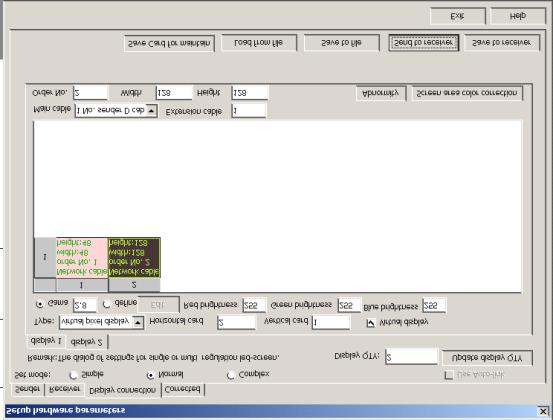
20 Sending card: If the green light is not blinking: check the clone of the graphics card and open clone. Make sure the RS232 (serial cable) is connected. Reinstall the driver of the graphics card and click Default in Option - software setup - input Linsn sender would solve the data problem in the sender. 2.Shown in below figure, click Display connection, input display QTY, for example, if a sending card supports 3 displays, input number: 3, if one, input number: 1;then click Update display QTY, Setup type of screen, such as full-color, double-color, etc., Input the card qty, X (width), Y (height), and then the computer will show the connection scheme, (Remark: the connection scheme is the copy as you face the Led display; one small box stands for a receiving card) The receiving card that first gets signals from sending card is Order No.1, Then input figures, for example, main cable: No.1, extension cable: 1, order No.: 1, width: 192, height: 128; Remarks: mail cable: because maximum four sending cards can be cascaded, and each sending card has two signal-output ports, there are 8 options for choosing. 1 No. sender U cable (1U) means the cable connect to the U port (near the lights) of the first sending card. The receiving card connected with the fist receiving card as Order No. 2, then input figures; Click Send to receiver. Each receiving card can be set to support the same pixels or different pixels or no pixel (suitable for irregular screen.), Send the data to receiving card or save it (.CON) in the computer file. 46

21 The upper box means: one sending card supports two displays, one (Display 1) uses the U port of the sending card, the other (Display 2) using the D port of the sending card. The upper box is the display connection of display1. Display 1 is real pixel; has four receiving cards,; when user looks at the front side of the display, the first receiving card is placed at the left top cabinet, supporting 120 pixels width, 48 pixels height. The following box is the display connection of display 2. Display 2 is virtual pixel and showing signs in virtual mode. Display 2 has two receiving card. One receiving card supports 48 pixels width, 48 pixels height; the other receiving card supports 128 pixel width and 128 height. 47
22 48
23 Chapter III the Communication Cable Making Method The making method is the same as that of international standard network cable(rj45). It has two types: 568A and 568B, and we usually use 568B. 49
Linsn TS802 LED Card,SD802D LED Control Card
 Linsn TS802 LED Card,SD802D LED Control Card Linsn >> LED Sending Card >> TS802 LED Card TS802 LED Sending Card,SD802D LED Data Transmitter Function:Receiving signals from computer then fedding to receiving
LedSet User s Manual V Official website: 1 /
 LedSet User s Manual V2.6.1 1 / 42 20171123 Contents 1. Interface... 3 1.1. Option Menu... 4 1.1.1. Screen Configuration... 4 1.1.1.1. Instruction to Sender/ Receiver/ Display Connection... 4 1.1.1.2.
V9A01 Solution Specification V0.1
 V9A01 Solution Specification V0.1 CONTENTS V9A01 Solution Specification Section 1 Document Descriptions... 4 1.1 Version Descriptions... 4 1.2 Nomenclature of this Document... 4 Section 2 Solution Overview...
CONTENTS. Section 1 Document Descriptions Purpose of this Document... 2
 CONTENTS Section 1 Document Descriptions... 2 1.1 Purpose of this Document... 2 1.2 Nomenclature of this Document... 2 Section 2 Solution Overview... 4 2.1 General Description... 4 2.2 Features and Functions...
Quick Guide Book of Sending and receiving card
 Quick Guide Book of Sending and receiving card ----take K10 card for example 1 Hardware connection diagram Here take one module (32x16 pixels), 1 piece of K10 card, HUB75 for example, please refer to the
Statement SmartLCT User s Manual Welcome to use the product from Xi an NovaStar Tech Co., Ltd. (hereinafter referred to as NovaStar ). It is our great
. It is our great") LED Display Configuration Software SmartLCT User s Manual Software Version: V3.0 Rev3.0.0 NS110100239 Statement SmartLCT User s Manual Welcome to use the product from Xi an NovaStar Tech Co., Ltd. (hereinafter
LED Display Configuration Software SmartLCT User s Manual Software Version: V3.0 Rev3.0.0 NS110100239 Statement SmartLCT User s Manual Welcome to use the product from Xi an NovaStar Tech Co., Ltd. (hereinafter
HD-A60X Series Asynchronous-Synchronous operate manual
 Catalogue Chaper1 Summary... 1 1.Hardware structure... 2 2.Controller working system... 2 3.Running environment... 3 Chaper2 Adjust display procedure... 4 Chaper3 Hardware connected... 5 1 The port detais
TV Character Generator
 TV Character Generator TV CHARACTER GENERATOR There are many ways to show the results of a microcontroller process in a visual manner, ranging from very simple and cheap, such as lighting an LED, to much
HD-D10/D20/D30 Series Asynchronous operate manual. Chapter1 Summary
 HD-D10/D20/D30 Series Asynchronous operate manual Chapter1 Summary HDPlayer Software we promoting for Full Color door head display. It can remote display by long distance, play high definition video, picture
VSP 168HD Quick Start
 VSP 168HD Quick Start Support 10Gbps of transmission rate Support HDBaseT protocols and standards Support USB upgrade Max 2048 1152@60Hz/2560 816 60Hz input/output resolution Support custom output resolution
User Manual. Multi-Screen Splicing Processor J6
 User Manual Multi-Screen Splicing Processor J6 Rev1.0.0 NS160100147 Statement Dear users, Welcome to use the J6, a multi-screen splicing processor. This manual is intended to help you to understand and
XI'AN NOVASTAR TECH CO., LTD
 Document number: NOVA2013-MCTRL660-HB-01 Version: V1.2.0 M3 Controller MCTRL660 User Manual Xi an NovaStar Tech Co., LTD 1 Overview MCTRL660, NovaStar's latest independent master control, is mainly applied
Specifications. Independent Controller MCTRL R5. Rev1.0.0 NS
 Specifications Independent Controller MCTRL R5 Rev1.0.0 NS1601000126 Overview MCTRL R5 is an independent master controller developed by NovaStar with an epoch-making significance. The loading capacity
SXGA096 DESIGN REFERENCE BOARD
 SXGA096 DESIGN REFERENCE BOARD For Use with all emagin SXGA096 OLED Microdisplays USER S MANUAL VERSION 1.0 TABLE OF CONTENTS D01-501152-01 SXGA096 Design Reference Board User s Manual i 1. INTRODUCTION...
VSP 9516S Quick Start
 VIEWSIZE THE WORLD VSP 9516S Quick Start Max 2048 1152@60Hz/2560 816 60Hz input/output resolution User-defined resolution adjustment Picture in picture Audio and video sync Seamless switching between inputs
VSP 198CVS Quick Start
 VIEWSIZE THE WORLD VSP 198CVS Quick Start Max 2048 1152@60Hz/2560 1152 50Hz input/output resolution User customize output resolution 3G/HD/SD-SDI input Multiple cascade mapping for super resolution DVI
Outdoor & Indoor Full Color LED Display Screen. Installation Manual
 SHENZHEN VISULAL LUMEN CO.,LTD. Outdoor & Indoor Full Color LED Display Screen Installation Manual Thank you for your selected Visuallumen's outdoor & Indoor Full Color LED Display. For proper operation,
B. The specified product shall be manufactured by a firm whose quality system is in compliance with the I.S./ISO 9001/EN 29001, QUALITY SYSTEM.
 VideoJet 8000 8-Channel, MPEG-2 Encoder ARCHITECTURAL AND ENGINEERING SPECIFICATION Section 282313 Closed Circuit Video Surveillance Systems PART 2 PRODUCTS 2.01 MANUFACTURER A. Bosch Security Systems
VSP 516S Quick Start
 VIEWSIZE THE WORLD VSP 516S Quick Start Max 2048 1152@60Hz/2560 816 60Hz input/output resolution User customize output resolution 3G/HD/SD-SDI input Multiple cascade mapping for super resolution Seamless
J6 User Manual. User Manual. Multi-Screen Splicing Processor J6. Xi an NovaStar Tech Co., Ltd. Rev1.0.1 NS
 J6 User Manual User Manual Multi-Screen Splicing Processor J6 Rev1.0.1 NS160110162 Statement Dear users, You are welcome to use the J6, a multi-screen splicing processor of Xi'an NovaStar Tech Co., Ltd.
MultiQ Digital signage template system for widescreen monitors
 Technical Note MultiQ Digital signage template system for widescreen monitors This document is intended as a guide for users of the MultiQ Digital Signage Template System for widescreen monitors in landscape
LedSync820C LED Video Processor USER S MANUAL
 LedSync820C LED Video Processor USER S MANUAL TABLE OF CONTENTS I. Safety precautions ----------------------------------------------------------------- 3 II. Connections of hardware 1.Rear view ------------------------------------------------------------
ivw-fd122 Video Wall Controller MODEL: ivw-fd122 Video Wall Controller Supports 2 x 2 Video Wall Array User Manual Page i Rev. 1.
 MODEL: ivw-fd122 Video Wall Controller Supports 2 x 2 Video Wall Array User Manual Rev. 1.01 Page i Copyright COPYRIGHT NOTICE The information in this document is subject to change without prior notice
LVP602S LED Video Processor USER S MANUAL
 LVP602S LED Video Processor USER S MANUAL TABLE OF CONTENTS I. Safety precautions 3 II. Connections of hardware 1.Rear view 4 2. Port description 4 III. Frontal panel operations 1. Diagram of frontal panel
Operating Instructions
 Marshall Electronics Broadcast A/V Division Model No. VSW-2200 4-Input Seamless SDI A/V Switcher Operating Instructions Table of Contents 1. Overview... 2. Features.... Package Contents... 4. Specifications...
Chapter 23 Dimmer monitoring
 Chapter 23 Dimmer monitoring ETC consoles may be connected to ETC Sensor dimming systems via the ETCLink communication protocol. In this configuration, the console operates a dimmer monitoring system that
Logic Controls LV3000 VGA Connected Virtual Pole Display
 One Blue Hill Plaza, 16 th Floor, PO Box 1546 Pearl River, NY 10965 1-800-PC-AMERICA, 1-800-722-6374 (Voice) 845-920-0800 (Fax) 845-920-0880 Logic Controls LV3000 VGA Connected Virtual Pole Display This
Ydea-C5 System. Automatic Brightness Adjustment_DMX User Manual
 Ydea-C5 System Automatic Brightness Adjustment_DMX User Manual Automatic Brightness Adjustment_DMX includes 3 modes: timing adjustment, light sensation adjustment, and brightness priority; 1 Timing adjustment:
Table of content. Table of content Introduction Concepts Hardware setup...4
 Table of content Table of content... 1 Introduction... 2 1. Concepts...3 2. Hardware setup...4 2.1. ArtNet, Nodes and Switches...4 2.2. e:cue butlers...5 2.3. Computer...5 3. Installation...6 4. LED Mapper
H.264 HDMI Extender over IP Extender With LED, Remote, POE, RS232 Operating Instruction
 H.264 HDMI Extender over IP Extender With LED, Remote, POE, RS232 Operating Instruction 1 Introduction This HDMI over IP Extender use the advanced H.264 as the compression type, which makes it occupy lower
Lecture 14: Computer Peripherals
 Lecture 14: Computer Peripherals The last homework and lab for the course will involve using programmable logic to make interesting things happen on a computer monitor should be even more fun than the
-TECH DIGITAL. Explore The High DefinitionWorld. Website: Hot Line: [US] USER MANUAL
![-TECH DIGITAL. Explore The High DefinitionWorld. Website: Hot Line: [US] USER MANUAL](/thumbs/80/80689593.jpg "-TECH DIGITAL. Explore The High DefinitionWorld. Website: Hot Line: [US] USER MANUAL") -TECH DIGITAL Explore The High DefinitionWorld Website: www.jtechdigital.com Hot Line: 1-888-610-2818[US] USER MANUAL J-Tech Digital ProAV H.264 Encoder/Decoder Many to Many HDMI Extender RoHS 1 Operating
-TECH DIGITAL Explore The High DefinitionWorld Website: www.jtechdigital.com Hot Line: 1-888-610-2818[US] USER MANUAL J-Tech Digital ProAV H.264 Encoder/Decoder Many to Many HDMI Extender RoHS 1 Operating
User's Manual of LED LIGHTING CONTROL SYSTEM (VC-500A/B) VISS LIGHTING (SHENZHEN) CO.,LTD.
 VISS LIGHTING (SHENZHEN) CO.,LTD.") User's Manual of LED LIGHTING CONTROL SYSTEM (VC-500A/B) VISS LIGHTING (SHENZHEN) CO.,LTD www.viss.cn CONTENTS Part One LED LIGHTING CONTROL SYSTEM 1.Safety warning... 1-1 2.System description... 1-1 3.Parameter
User's Manual of LED LIGHTING CONTROL SYSTEM (VC-500A/B) VISS LIGHTING (SHENZHEN) CO.,LTD www.viss.cn CONTENTS Part One LED LIGHTING CONTROL SYSTEM 1.Safety warning... 1-1 2.System description... 1-1 3.Parameter
ivw-fd133 Video Wall Controller MODEL: ivw-fd133 Video Wall Controller Supports 3 x 3 and 2 x 2 Video Wall Array User Manual Page i Rev. 1.
 MODEL: ivw-fd133 Video Wall Controller Supports 3 x 3 and 2 x 2 Video Wall Array User Manual Rev. 1.01 Page i Copyright COPYRIGHT NOTICE The information in this document is subject to change without prior
VIDEO GRABBER. DisplayPort. User Manual
 VIDEO GRABBER DisplayPort User Manual Version Date Description Author 1.0 2016.03.02 New document MM 1.1 2016.11.02 Revised to match 1.5 device firmware version MM 1.2 2019.11.28 Drawings changes MM 2
User s Manual For LDU8000R
 Contents 1. Introduction of LDU8000R... 4 2. Hardware... 5 2.1 Control Buttons and Output Ports... 5 2.2 Cables... 7 3. Application... 9 3.1 One Display Controlled By One LDU... 9 3.2 Four Displays Controlled
Syntor X Flash Memory Module Revision C
 Syntor X Flash Memory Module Revision C The PIEXX SynXFlash memory module, along with the supplied PC software, replaces the original SyntorX code plugs and allows you to easily set modify and update your
EAN-Performance and Latency
 EAN-Performance and Latency PN: EAN-Performance-and-Latency 6/4/2018 SightLine Applications, Inc. Contact: Web: sightlineapplications.com Sales: sales@sightlineapplications.com Support: support@sightlineapplications.com
WV-NP1004. Network Operating Instructions. Network camera. Model No. (Lens is option.)
") Network camera Network Operating Instructions Model No. WV-NP1004 PUSH TO LOCK/EJECT WV-NP1004 (Lens is option.) Before attempting to connect or operate this product, please read these instructions carefully
Network camera Network Operating Instructions Model No. WV-NP1004 PUSH TO LOCK/EJECT WV-NP1004 (Lens is option.) Before attempting to connect or operate this product, please read these instructions carefully
Model 5250 Five Channel Digital to Analog Video Converter Data Pack
 Model 5250 Five Channel Digital to Analog Video Converter Data Pack E NSEMBLE D E S I G N S Revision 3.1 SW v2.0.1 This data pack provides detailed installation, configuration and operation information
I.Safety Prevention Measures
 I.Safety Prevention Measures Please always place this device on a stable surface; otherwise, it may fall and be damaged. The altitude and the tropical environment the adapter fits depend on which adapter
APM CALIBRATION PROCEDURE Rev. A June 3, 2015
 APM CALIBRATION PROCEDURE Rev. A June 3, 2015 Calibration of the APM allows system parameters such as coupler coupling values, interconnecting cable losses and system feeder losses to be programmed into
VIDEO ALARM VERIFICATION UNIT VIVER
 VIDEO ALARM VERIFICATION UNIT VIVER viver_en 09/08 The VIVER module provides remote video alarm verification, based on image sequences transmitted from cameras installed in the protected facility. The
C8000. sync interface. External sync auto format sensing : AES, Word Clock, Video Reference
 features Standard sync module for a frame Internal sync @ 44.1 / 48 / 88.2 / 96kHz External sync auto format sensing : AES, Word Clock, Video Reference Video Reference : Black Burst (NTSC or PAL) Composite
P-2 Installing the monitor (continued) Carry out as necessary
 Carry out as necessary") P-2 Installing the monitor (continued) Carry out as necessary Using the monitor without the bezel MDT552S satisfies the UL requirements as long as it is used with the bezel attached. When using the monitor
P-2 Installing the monitor (continued) Carry out as necessary Using the monitor without the bezel MDT552S satisfies the UL requirements as long as it is used with the bezel attached. When using the monitor
Therefore, HDCVI is an optimal solution for megapixel high definition application, featuring non-latent long-distance transmission at lower cost.
 Overview is a video transmission technology in high definition via coaxial cable, allowing reliable long-distance HD transmission at lower cost, while complex deployment is applicable. modulates video
MXS Strada USER GUIDE
 MXS Strada USER GUIDE AiM TECH Srl. Via Cavalcanti, 8 20063 Cernusco S/N (MI) Italia Tel. (+39) 02.9290571 Made in Italy www.aim-sportline.com MXS Strada 01. INTRODUCTION 02. WHAT IS IN THE KIT 03. LAYOUT
SingMai Electronics SM06. Advanced Composite Video Interface: HD-SDI to acvi converter module. User Manual. Revision 0.
 SM06 Advanced Composite Video Interface: HD-SDI to acvi converter module User Manual Revision 0.4 1 st May 2017 Page 1 of 26 Revision History Date Revisions Version 17-07-2016 First Draft. 0.1 28-08-2016
RMS 8424S Quick Start
 VIEWSIZE THE WORLD RMS 8424S Quick Start Standard 4 unit rack mount size 8 inch LCD 2 1024 3 (RGB) 600 16:9 / 4:3 adjustable SDI/HDMI embedded audio output via 3.5mm earphone socket Support SDI/DVI audio
MBI5050 Application Note
 MBI5050 Application Note Foreword In contrast to the conventional LED driver which uses an external PWM signal, MBI5050 uses the embedded PWM signal to control grayscale output and LED current, which makes
LCD MONITOR. quick start guide P2070,P2270,P2370,P2070G,P2270G,P2370G
 LCD MONITOR quick start guide P2070,P2270,P2370,P2070G,P2270G,P2370G ii Introduction Package Contents Please make sure the following items are included with your monitor. If any items are missing, contact
RF Solution for LED Display Screen
 RF Solution for LED Display Screen Introduction RF is a kind of wireless telecommunication technology, now standard IEEE802.11B is much popular. Communication speed between server and terminal can reach
Live events staging. Media centers
 Christie Spyder X80 80 megapixel, true 4K@60Hz performance across multiple displays Auditoriums Control rooms Live events staging Post-production Broadcast studios Corporate lobbies Media centers Sports
G ARD SECURITY SYSTEM Product Listing 2007
 G ARD SECURITY SYSTEM Product Listing 2007 G ARD L2000 WIRELESS ALARM SYSTEM Totally Wireless Wireless Telephone G'ARD L-2000 Wireless Alarm System uses the state of art microprocessor for data processing.
PRODUCT MANUAL. Product Description. Waterproof 4 Channel DMX to RGB-W LED Controller
 4 Channel to RGB-W LED Controller Waterproof 4 Channel to RGB-W LED Controller Product Description Thank you for purchasing Solid Apollos Waterproof 4 Channel to RGBW LED Controller. It is a new standard
IP LIVE PRODUCTION UNIT NXL-IP55
 IP LIVE PRODUCTION UNIT NXL-IP55 OPERATION MANUAL 1st Edition (Revised 2) [English] Table of Contents Overview...3 Features... 3 Transmittable Signals... 3 Supported Networks... 3 System Configuration
EVLED EVLED MEDIA SCREEN EVLED 1024 SMD TRI R / G / B EVLED 1024 R / G / B EVLED 256 R / G / B. Lighting Designer: Travis Shirley
 EVLED Enrique Iglesias Tour Lighting Designer: Travis Shirley EVLED MEDIA SCREEN s e r i e s EVLED 1024 SMD TRI R / G / B EVLED 1024 R / G / B EVLED 256 R / G / B EVLED 1024 SMD TRI R / G / B Model Transparency:
Single cable multiswich programmer PC102W
 Single cable multiswich programmer PC102W 1. Product description The PC102W - single cable multiswich programmer (in the text - programmer) is useful instrument while configuring and troubleshooting SAT
PQ-Box 100 Quick Start Instructions
 PQ-Box 100 Quick Start Instructions These instructions are provided for the purpose on providing a quick start to PQ-Box 100 installation and operation. Please refer to the user handbook for full details.
Statement Dear users: Welcome to use Nova's Products. We are pleased to offer this manual to help you understand and use the product. In the preparati
 User's Manual LED Display Video Controller VX4 VX4S Rev1.0.0 NS160100018 Statement Dear users: Welcome to use Nova's Products. We are pleased to offer this manual to help you understand and use the product.
O P E R A T I O N M A N U A L. RF-Reader. Stand-alone-Reader Leser 2plus with RS-232 interface
 O P E R A T I O N M A N U A L Version 01/05 RF-Reader Stand-alone-Reader Leser 2plus with RS-232 interface Important! Read by all means! To maintain the perfect shipping conditions and to ensure safe operation
HD4112 Quad HDMI MPEG2 HD DVBT Encoder Modulator U S E R M A N U A L
 HD4112 Quad HDMI MPEG2 HD DVBT Encoder Modulator U S E R M A N U A L HD4112 Manual Rev 1 Contents 1. GENERAL 1.1 Description 1.2 Specifications 2. INSTALLATION 2.1 What s in the Box 2.2 Connection 2.2.1
VideoMate U3 Digital Terrestrial USB 2.0 TV Box Start Up Guide
 VideoMate U3 Digital Terrestrial USB 2.0 TV Box Start Up Guide Compro Technology, Inc. www.comprousa.com Copyright 2001-2005. Compro Technology, Inc. No part of this document may be copied or reproduced
We give 5* YEARS FULL WARRANTY on our boards and provide 24H/7 Customer Support
 TECHNICAL DATA of LARGE OUTDOOR VIDEO DISPLAYS Our LED (Light Emitting Diodes) video display boards are designed by PANASONIC and manufactured in their hi-tech factory in Japan and Taiwan. We also produce
Copyright 2018 Xi an NovaStar Tech Co., Ltd. All Rights Reserved. No part of this document may be copied, reproduced, extracted or transmitted in any
 Document Version: Document Number: V1.1.0 NS110100423 A8s Receiving Card Copyright 2018 Xi an NovaStar Tech Co., Ltd. All Rights Reserved. No part of this document may be copied, reproduced, extracted
Copyright 2018 Xi an NovaStar Tech Co., Ltd. All Rights Reserved. No part of this document may be copied, reproduced, extracted or transmitted in any
 MCTRL660 PRO Independent Controller Product Version: Document Number: V1.0.0 NS110100560 Copyright 2018 Xi an NovaStar Tech Co., Ltd. All Rights Reserved. No part of this document may be copied, reproduced,
TBS8030 HDMI Encoder User Guide
 TBS8030 HDMI Encoder User Guide Catalog 1. Product Overview... 2 1.1 Product Presentation... 2 1.2 Product Specifications... 3 2. Quick Start... 4 3. TBS Capture Software Settings... 4 3.1 HDMI Capture
LedSync820B. LED Video Image Processor USER S MANUAL
 LedSync820B LED Video Image Processor USER S MANUAL I. Safety Precautions Danger! There is high voltage in the processor, to prevent any unexpected hazard, unless you are a maintenance, please do not open
Design of VGA Controller using VHDL for LCD Display using FPGA
 International OPEN ACCESS Journal Of Modern Engineering Research (IJMER) Design of VGA Controller using VHDL for LCD Display using FPGA Khan Huma Aftab 1, Monauwer Alam 2 1, 2 (Department of ECE, Integral
TRIMBLE GPS / 10MHz REFERENCE MONITOR DISPLAY V January 2015
 TRIMBLE GPS / 10MHz REFERENCE MONITOR DISPLAY V1.2-1.4 January 2015 A display and command module for the Trimble Thunderbolt GPS with 10MHz reference oscillator. by Hubbatech Software Revision Notes: 1.2-2014
G406 application note for projector
 G406 application note for projector Do you have trouble in using projector internal warp and edge blending function? Inconvenient in multiple signal source connection System resolution is not enough after
Operation and Installation Guide
 Operation and Installation Guide HDS2800 Series Encoder Modulator High Definition (HD) Digital COFDM MPEG2 and H.264 Modulator with IP Multicast. 19 Rack Mount Revision 4.0 Firmware version Released File
Dragon. manual version 1.6
 Dragon manual version 1.6 Contents DRAGON TOP PANEL... 2 DRAGON STARTUP... 2 DRAGON STARTUP SCREEN... 2 DRAGON INFO SCREEN... 3 DRAGON MAIN SCREEN... 3 TURNING ON A TRANSMITTER... 4 CHANGING MAIN SCREEN
D-901 PC SOFTWARE Version 3
 INSTRUCTION MANUAL D-901 PC SOFTWARE Version 3 Please follow the instructions in this manual to obtain the optimum results from this unit. We also recommend that you keep this manual handy for future reference.
CONTENT Product Introduction... 2 Packing Configuration...3 Hardware Orientation... 4 Front Panel... 4 Back Panel... 6 Using Your Product... 7 Content
 VENUS X1PRO Quick Start 4K input support in DP, HDMI and DVI Input standard 2K formats Scale and switch seamlessly between 2K and 4K inputs Output to any format 2K or 4K EDID management on board HDCP 2.0
VS-TV. User manual. Virtual Matrix ENGLISH
 ENGLISH VS-TV User manual Virtual Matrix INDEX 1 INTRODUCTION... 2 1.1 FEATURES.... 2 2 INSTALLATION AND SET UP... 3 2.1 UNIT PACKAGE CONTENTS... 3 2.2 INSTALLATION... 3 2.3 UNIT SET UP... 3 3 CONFIGURATION
Matrix Switcher. Users Guide ANI-VGA ANI-V ANI-RGB
 Matrix Switcher Users Guide ANI-VGA ANI-V ANI-RGB Document version: 052012 For use of the device and safety of users, please follow the instructions when installing, using and maintaining: The system must
16 Universe LED Matrix Panels Instructions
 Congratulations on buying the high performance LED matrix controller. Eight matrix LED panels 16x32 (8 to 1 scan) Four/Two LED panels 32x32 or 32x64 (16 to 1 scan) Full 24 bit color for 16 million colors,
Copyright 2018 Xi an NovaStar Tech Co., Ltd. All Rights Reserved. No part of this document may be copied, reproduced, extracted or transmitted in any
 MCTRL4K Independent Controller Product Version: Document Number: V1.0.3 NS110100428 Copyright 2018 Xi an NovaStar Tech Co., Ltd. All Rights Reserved. No part of this document may be copied, reproduced,
DVB-T Box, USB Monheim/Germany Tel. +49 (0)9091/ Fax +49 (0)9091/ Hama GmbH & Co KG.
9091/ Fax +49 (0)9091/ Hama GmbH & Co KG.") www.hama.de Hama GmbH & Co KG Postfach 80 86651 Monheim/Germany Tel. +49 (0)9091/502-0 Fax +49 (0)9091/502-274 hama@hama.de www.hama.de 00062776-01.05 DVB-T Box, USB 2.0 00062776 L TV USB receiver User
www.hama.de Hama GmbH & Co KG Postfach 80 86651 Monheim/Germany Tel. +49 (0)9091/502-0 Fax +49 (0)9091/502-274 hama@hama.de www.hama.de 00062776-01.05 DVB-T Box, USB 2.0 00062776 L TV USB receiver User
Xi an NovaStar Tech Co., Ltd. User's Manual. LED Video Controller VX4S/VX4. Rev1.1.2 NS
 User's Manual LED Video Controller VX4S/VX4 Rev1.1.2 NS160110080 Statement You are welcome to use the products from (hereinafter referred to as Novastar). It is our great pleasure to offer this manual
SHOWLINE SL NITRO 510C LED STROBE LUMINAIRE SPECIFICATIONS.
 GENERAL. A.) Overview. SHOWLINE SL NITRO 510C LED STROBE LUMINAIRE SPECIFICATIONS. The luminaire shall be an LED strobe luminaire employing five hundred and twenty eight (528) red, green, blue and white
AMIQ-K2 Program for Transferring Various-Format I/Q Data to AMIQ. Products: AMIQ, SMIQ
 Products: AMIQ, SMIQ AMIQ-K2 Program for Transferring Various-Format I/Q Data to AMIQ The software AMIQ-K2 enables you to read, convert, and transfer various-format I/Q data files to AMIQ format. AMIQ-K2
Imposa Velo V User s Manual. Content 1 Tile introduction Specification Components introduction Power box...
 User s Manual Content 1 Tile introduction...4 1.1 Specification...4 1.2 Components introduction...6 1.2.1 Power box... 6 1.2.2 Hub box(hub)...6 1.2.3 VPU2000...7 1.2.4 Bar Tiles... 8 1.2.5 Cables...9 1.3
User Manual rev: Made in Taiwan
 CV-500S HDMI to Component/CVBS & Audio Scaler Converter User Manual rev: 131218 Made in Taiwan The CV-500S HDMI to Component/CVBS & Audio Scaler Converter has been tested for conformance to safety regulations
DVB-T USB SET-TOP BOX
 DVB-T USB SET-TOP BOX User Manual Version: 1.0 (February 2005) TRANSYSTEM INC. No.1-2 Li-Hsin Rd.I Science-Based Industrial Park, Hsinchu, Taiwan Tel:+886-3-5780393 Fax:+886-3-5784111 e-mail: sales@transystem.com.tw
Advanced Test Equipment Rentals ATEC (2832)
") E stablished 1981 Advanced Test Equipment Rentals www.atecorp.com 800-404-ATEC (2832) Technical Datasheet Scalar Network Analyzer Model 8003-10 MHz to 40 GHz The Giga-tronics Model 8003 Precision Scalar
E stablished 1981 Advanced Test Equipment Rentals www.atecorp.com 800-404-ATEC (2832) Technical Datasheet Scalar Network Analyzer Model 8003-10 MHz to 40 GHz The Giga-tronics Model 8003 Precision Scalar
The user manual of LED display screen and RH-32G control card.
 The user manual of LED display screen and RH-32G control card. ⅠHardware parameters 1 The maximum number of points P10 solid color:32*768 32*256(2 pieces high and 24 pieces wide;2 pieces high and 8 pieces
Intelligent Security and Fire Ltd
 User Manual Product ranges covered by this manual Vi-P14 Vi-P14A Document Reference Date Firmware Vi-Q4C1 Viq601a.doc 26/11/2009 From Viq001a21 Videoswitch Telephone 01252-851510 Ocean House, Redfields
BRIGHTLINK HDMI EXTENDER OVER ETHERNET - H METER MODEL: BL-EXT-IP-264
 BRIGHTLINK HDMI EXTENDER OVER ETHERNET - H.264-120 METER MODEL: BL-EXT-IP-264 Operating Instructions BRIGHTLINKAV.COM 1 Introduction This HDMI over IP Extender use the advanced H.264 as the compression
MadiXtreme / Alpha-Link XLogic I/O system for PC and Mac Setup Guide V1.0 XLogic. This is SSL.
 www.solidstatelogic.com MadiXtreme / Alpha-Link XLogic I/O system for PC and Mac Setup Guide V1.0 XLogic. This is SSL. Document History 82BSA101A March 2012 V1.0 Initial Release Contents Introduction 1
Video Series. HCS-4311M Professional Mixed Matrix for Conference 8.2. HCS-3313C High Quality Speed Dome Camera (ceiling) 8.5
 8.5") Video Video Series Series Video Tracking System 8.2 HCS-4311M Professional Mixed Matrix for Conference 8.2 HCS-3313C High Quality Speed Dome Camera (ceiling) 8.5 HCS-3313D High Quality Speed Dome Camera
Video Video Series Series Video Tracking System 8.2 HCS-4311M Professional Mixed Matrix for Conference 8.2 HCS-3313C High Quality Speed Dome Camera (ceiling) 8.5 HCS-3313D High Quality Speed Dome Camera
Statement Welcome to use the product from Xi an NovaStar Tech Co., Ltd. (hereinafter referred to as Novastar ). It is our great pleasure to offer this
. It is our great pleasure to offer this") User's Manual LED Display Video Controller VX2U/VX4U XI'AN NOVASTAR TEC Rev1.0.3 NS160100228 Statement Welcome to use the product from Xi an NovaStar Tech Co., Ltd. (hereinafter referred to as Novastar
User's Manual LED Display Video Controller VX2U/VX4U XI'AN NOVASTAR TEC Rev1.0.3 NS160100228 Statement Welcome to use the product from Xi an NovaStar Tech Co., Ltd. (hereinafter referred to as Novastar
12.1 Inch CGA EGA VGA SVGA LCD Panel - ID #492
 12.1 Inch CGA EGA VGA SVGA LCD Panel - ID #492 Operation Manual Introduction This monitor is an open frame LCD Panel monitor. It features the VESA plug & play system which allows the monitor to automatically
HDMI to 3G-SDI Scaler Installation Guide
 Introduction HDMI to 3G-SDI Scaler Installation Guide The HDMI to 3G-SDI Scaler allows you to broadcast HDMI signals from one source to two 3G-SDI outputs. Key Features and Benefits Convert HDMI signals
V6118 EM MICROELECTRONIC - MARIN SA. 2, 4 and 8 Mutiplex LCD Driver
 EM MICROELECTRONIC - MARIN SA 2, 4 and 8 Mutiplex LCD Driver Description The is a universal low multiplex LCD driver. The version 2 drives two ways multiplex (two blackplanes) LCD, the version 4, four
Industriefunkuhren. Technical Manual. OEM Sync-Module FE1000 (IRIG-B) ENGLISH
 ENGLISH") Industriefunkuhren Technical Manual OEM Sync-Module FE1000 (IRIG-B) ENGLISH Version: 07.02-24.03.2014 2 / 19 FE1000 IRIG-B Synchronisation - V07.02 IMPORTANT NOTES Version Number (Firmware / Manual) THE
Industriefunkuhren Technical Manual OEM Sync-Module FE1000 (IRIG-B) ENGLISH Version: 07.02-24.03.2014 2 / 19 FE1000 IRIG-B Synchronisation - V07.02 IMPORTANT NOTES Version Number (Firmware / Manual) THE
DT3162. Ideal Applications Machine Vision Medical Imaging/Diagnostics Scientific Imaging
 Compatible Windows Software GLOBAL LAB Image/2 DT Vision Foundry DT3162 Variable-Scan Monochrome Frame Grabber for the PCI Bus Key Features High-speed acquisition up to 40 MHz pixel acquire rate allows
AC335A. VGA-Video Ultimate Plus BLACK BOX Back Panel View. Remote Control. Side View MOUSE DC IN OVERLAY
 AC335A BLACK BOX 724-746-5500 VGA-Video Ultimate Plus Position OVERLAY MIX POWER FREEZE ZOOM NTSC/PAL SIZE GENLOCK POWER DC IN MOUSE MIC IN AUDIO OUT VGA IN/OUT (MAC) Remote Control Back Panel View RGB
C8188 C8000 1/10. digital audio modular processing system. 4 Channel AES/EBU I/O. features. block diagram. 4 balanced AES inputs
 features 4 balanced AES inputs Input Sample Rate Converters (SRC) 4 balanced AES outputs Relay bypass for pairs of I/Os Relay wait time after power up Master mode (clock master for the frame) 25pin Sub-D,