SAFETY. Unless otherwise stated TSL equipment may be installed at any angle or position within an -
|
|
|
- Russell Ball
- 6 years ago
- Views:
Transcription
1
2 P a g e 2 SAFETY Installation. Unless otherwise stated TSL equipment may be installed at any angle or position within an - All TSL equipment conforms to the EC Low Voltage Directive: EC Low Voltage Directive (73/23/EEC)(OJ L )(LVD). Amendment: (93/68/EEC) (OJ L ). In all cases the frame of the equipment must be earthed on installation. Where appropriate, the earth pin on the IEC mains inlet connector is connected to the metal frame of the equipment, to 0 volts on the internal DC PSU and to signal ground unless otherwise stated. All metal panels are bonded together. Check that the voltage selector setting (if fitted) and the fuse rating is correct for the local mains supply. Due consideration for cooling requirements must be given when mounting the equipment. It is recommended that a 1RU of rack space, or a vent panel, should be left above and below the unit.
3 P a g e 3 WARRANTY, MAINTENANCE AND REPAIR All TSL products have a one year warranty period starting from the date it leaves the factory. A repair warranty is to apply. That is, the product is to be returned for repair with no replacement and an exchange shipping policy is also to apply. TSL offers a seven day DOA policy together with an exchange shipping policy. That is, if a product has been declared dead on arrival within a seven day period a warranty replacement will be shipped. A temporary replacement may be available where, for operational reasons, it is imperative that service is continued. The customer will be asked to enter into a loan agreement for the duration of repair. All faulty equipment returned to TSL for repair will, where possible, be returned to the customer within seven working days. TSL Returns Procedure Please telephone +44 (0) (Fax: +44 (0) ) and ask for Customer Support, detailing the model and serial number of the equipment, who will provide a Returns Number. This will enable us to track the unit effectively and will provide some information prior to the unit arriving. For each item, this unique Returns Number must be included with the Fault Report sent with the unit. A contact name and telephone number are also required with the Fault Report sent with the unit. Fault report details required. Company: Name: Address: Contact Name: Telephone number: Fax number: address: Returns Number: Symptoms of the fault (to include switch setting positions, input signals etc): Packing Please ensure that the unit is well packed as all mechanical damage is chargeable. TSL recommends that you insure your equipment for transit damage. The original packaging, when available, should always be used when returning equipment. If returned equipment is received in a damaged condition, the damage should be reported both to TSL and the carrier immediately.
4 P a g e 4 This Page is Blank
5 P a g e 5 Table of Contents 1.0 Introduction Block Diagram Operation Controls and Displays - Overview Source Selection Analogue Audio Input Trim Channel Signal Format Selection Stereo Mix/Mon Modes Stereo Channel Format: Mono Channel Format: Group Channel Format: Group 2 PAIR ADD: Group 2 PAIR OFF: Group 5.1 DMIX: Group LRC DMIX: Channel Signal Format Selection Surround Sound Mix/Mon Modes Stereo Channel Format: Mono Channel Format: Group Channel Format: Group 5.1 ALL: Monitoring Input Channels Solo Function Monitoring Input Channels Mixer Function Audio Mixers 1 and Switching Audio Mixer 1 to 5.1 mode Configuring and Naming Input Channels X-Y Routing XY Routing Setup Internal Sources Physical Sources Choosing the active SDI input Physical Outputs Routing Status Window Overview Menu Page Conditional Routing Rules Lock and Unlock Selection Set as Default Routing System XY Crosspoint Map User Preset and Snapshot Management Home Button and User Presets User Presets SAVE Menu User Presets Recall Menu Setup Menu Meter Menu dbfs Menu Meter Peak Menu Meter Zero Menu Meter Hold Menu SDI Input Select Mixer 1 Mode Output Menu Setup 2 Menu User Save Menu Monitor Mode GPI Menu Internal / External Loudspeaker Mute Surround Mix Menu Software Menu Connectivity and pin-out details Analogue XLR Connectors Stereo Variable Output (Monitor Buss) Analogue Output Connector Analogue Input Connectors 1-4 and AES Input/Output Connectors 1-4 and
6 P a g e GPI Connector HD15 Socket Remote Control Connector/ RS D9 Socket DIP switch configuration functions To be confirmed Notes General Notes AVM TOUCH SERIES - Technical Specifications HD Standards Supported Performance Installed HDC-2T Audio Monitor Module Specification Overview Mechanical Power Inputs Outputs Loudspeakers GPI inputs Control... 49
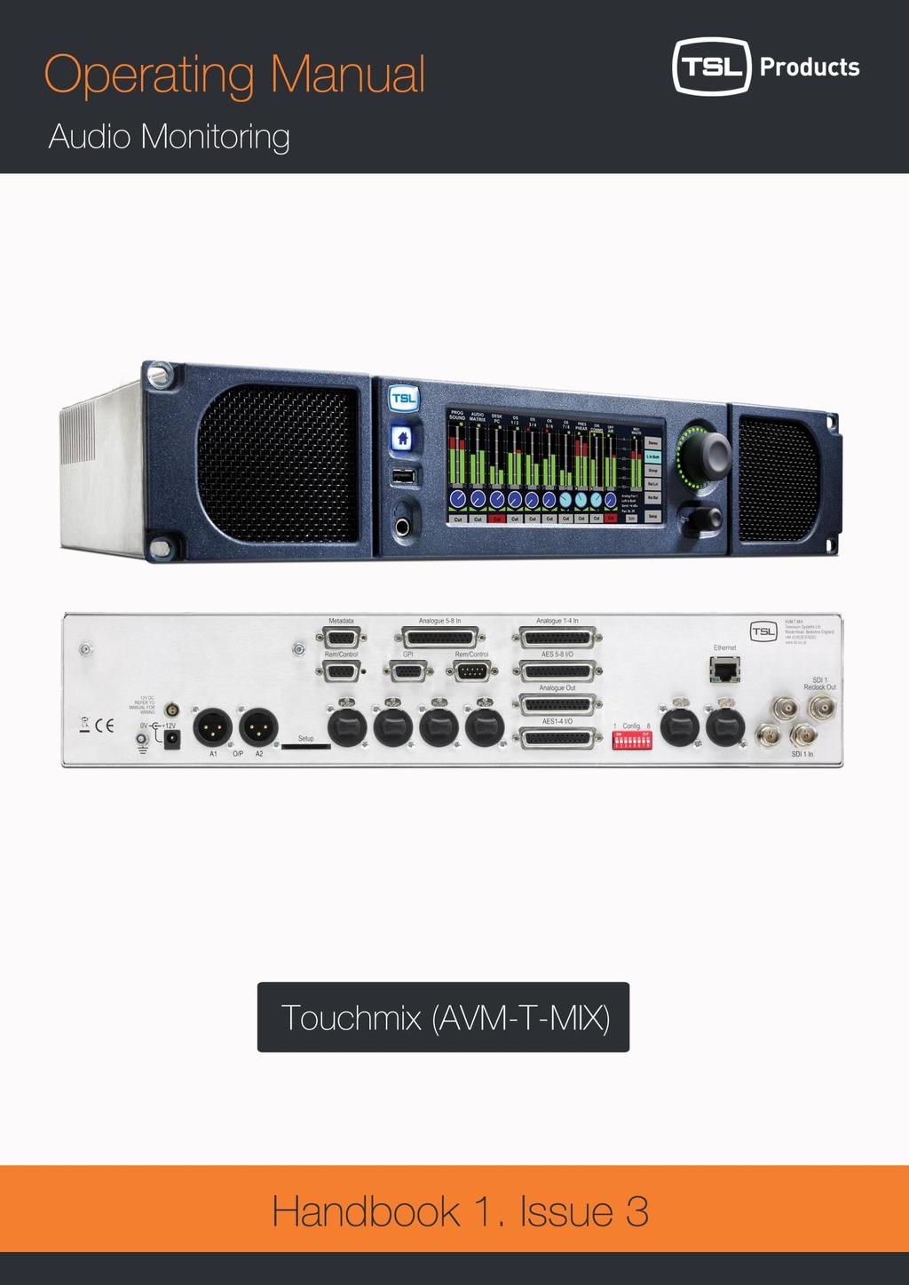
7 P a g e Introduction is the world s first rackmount Touchscreen controlled audio monitor unit. The Touch- Mix system delivers a unique combination of audio monitoring and channel mixing capabilities designed to simplify operations and workflow throughout the Television broadcast environment. The is a 2RU x 320mm Audio Mixer/Monitoring Unit controlled via a touch screen interface and assignable hardware controls. As with any new product which relies on complex software, it is possible that you may find minor bugs or perhaps think of enhancements which would improve the operation of. In the event of either scenario, please feel free to contact TSL via your local reseller or directly on , asking for the TOUCH SERIES Product Manager. TSL will be releasing upgrades and feature enhancements from time to time as a purchaser of you should receive these directly, free of charge, through your reseller or directly from TSL. Please refer to for announcements. The following features are standard: Single or Dual (SD Only) Auto-sensing, 1080p (60, 59, 94 and 50Hz), HD/SDI video input De-embedded audio monitoring from video (HD/SDI) with intuitive selection from up to sixteen channels (SDI 1 only), and eight channels (SDI 2 Group 1 and 2 only) 8 AES (8 Pairs/16 Channel) and 4 AES (4 Pairs/8 Channel SD Only) Inputs 110Ohm Balanced or 75 Ohm unbalanced via optional CAB-D25-BNC cable 8 Analogue Stereo Inputs Identical twin audio mixers 10 stereo/ 20 dual mono assignable input channels per mixer 5.1 audio mixing and monitoring capability Full input / output XY routing function Surround Sound Speaker Output Support Downmix of discrete multichannel audio to stereo for compatibility monitoring Re-clocked HD/SDI video output. Choice of user selectable bargraph scales (BBC PPM, EBU PPM, EBU Digital, Nordic, VU and DIN) 18 User programmable presets. Home button for instant recall of default operating condition Manage, recall and save favourite configurations via USB stick or SD card Fixed or variable analogue stereo outputs (mixer 1 and 2) Fixed or variable AES stereo outputs (mixer 1 and 2) Variable stereo analogue outputs (Monitor Buss) High quality internal full range loudspeaker system Dual 12V DC inputs Serial remote control Headphone output with LS muting Compact, lightweight (5.1Kg) 2RU case, 320mm deep
8 P a g e 8

9 P a g e Block Diagram
10 P a g e Operation The is designed to be user friendly and intuitive to operate. The menus and functions will feel familiar to both users of TSL multichannel audio monitoring products and those buying a TSL solution for the first time. Important Note: ships with a default 0dBu reference level set to -18 dbfs, the default operating scale is EBU Digital. The operational reference level for the unit can easily be changed via the Setup menu (described elsewhere in this handbook).
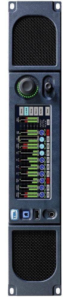
11 P a g e Controls and Displays - Overview. 4-Driver Loudspeaker System Home Preset Instant Recall Dual Action Monitoring Level Control w/cut, Dim CLEAN FX LIVE OB ST. MIC1 COMMS PGM PGM L R PGM C LFE PGM LS RS AES MON OFF AIR NO INPUT MIX 1 MSTR 0 Stereo Mono 30 LCR Dmix Rst Lvl Cut Cut Cut Cut Cut Cut Cut Cut Cut Cut SDI 1 pair 1 LCR DMIX Send: 0.0dB Bal: L = R Solo Rst Bal Setup USB Port for Field Upgrades and System Backup 22:9 Aspect Ratio LCD Touch Screen Dual Function Encoder Level Send/Push for Pan/Balance is equipped with a 4 driver loudspeaker system comprising left/right tweeter and dual subwoofer units. Menus and features are navigated via the 22:9 aspect ratio touch screen. The front panel USB connector is used for software upgrades; favourite user preset storage and preset recall. User presets can be recalled and stored locally using the Home button. Loudspeaker and headphone volume is adjusted by the master level control. This dual action rotary encoder also features push to Cut/Dim functionality. The dual function rotary encoder is rotated to control channel level send with pan/balance activated by push and turn.
12 P a g e 12 Touch and Hold Bargraph for Source Selection Touch and Hold Mix Master Bargraph to Select Mix 1 or Mix 2 Input configurations Input Channel Format Selection Level Send and Bal/Pan Indication Stereo/Mono/Group Channel Status Individual Channel Cut Switch Selected Channel Status and Solo Button Touch and Hold channel bargraph to activate input selection menu. Upon selection of input, selected channel format is selected via the Stereo/Mono/Group buttons. Selected channel gain and Bal/Pan level indicated by icons below bargraph display. Stereo/Mono/Group channel format denoted by colour of level send control and pips beneath bargraph pairs. Individual channels can be cut from main mix buss. Individual channels can be soloed to monitoring output buss. features two entirely independent Audio Mixers. Touch and Hold Mix Master Bargraph to toggle between Mixer 1 and Mixer 2. Mixer 1 can be configured for stereo and 5.1 outputs

13 P a g e 13 Input Channels with 10 Character User Mnemonic Names Unused Input Channels Routed to No Input Names Channels defined as Group in either 2 Pair, 5.1 or LRC formats Channel defined as Mono, Left Only or Right Only formats Channel defined as Stereo format Selected Channel overview including Input Source, Format, Send level and Input sources named with a user defined 10 character mnemonic displayed above the channel bargraph. Unused input channels can be routed to Silence displayed as No Input. Channel Group format is denoted by use of Magenta or Yellow colouration. Channel Group formats include 2 Pair, 5.1 Downmix, LRC Downmix (as shown above) and 5.1 ALL. Channel Stereo format is denoted by use of Electric Blue or Silver colouration. Channel Mono format is denoted by use of Cyan colouration. Channel Mono formats include L+R, Left to both and Right to both (as shown above). Selected Channel status shown in information box includes Source, Format, Send level and Bal/Pan adjustment.
. Each can be configured with its own setup and used in diverse applications.")

14 P a g e Source Selection Key to the ease of operation of is the simplicity by which audio may be monitored and/or mixed. As described previously, is equipped with two completely independent mixer/monitor systems (Mixer 1 and Mixer 2). Each can be configured with its own setup and used in diverse applications. Mixer 1 may be used as primary audio monitor in any application whilst the secondary mixer might be used as a simple de-embedder to back-feed another part of the system or even as a means to derive a headphone cue to a voice over artist or commentator. Setting up the monitor for use is simple and intuitive yet incredibly powerful. Source Selection SD Source Selection By simply touching and holding the desired channel the SOURCE menu selection is automatically activated. Select the signal type/pair or SILENCE if no selection is required and the chosen audio will be routed to the channel pair. If the selected input has been configured with a User Name then the text string will be displayed above the bargraph pair. Audio is automatically routed to the selected channel from an active input and the signal activity displayed on the bargraph. To hear the incoming audio instantly, simply press SOLO and turn up the volume. Touch BACK to exit the SOURCE menu.
.")
15 P a g e Analogue Audio Input Trim is designed to be used with balanced or unbalanced analogue audio inputs. If one of the analogue inputs has been wired to an unbalanced signal source then the user may need to compensate for signal loss (typically -6dB). If this is the case then gain can be added to the chosen analogue input in steps of 3dB by touching the button displayed below via the Setup/Input menu. Please note that the does not have an analogue signal amplifier and that the gain is added in the digital domain. If gain is added to an unbalance analogue audio input in this way then the signal to noise ratio of that signal will be affected accordingly and low level hiss may be heard in exceptional circumstances. Press to access Input Trim for low level or unbalanced analogue audio


, Left (to Both) and Right (to Both) formats.")
16 P a g e Channel Signal Format Selection Stereo Mix/Mon Modes Applicable to Stereo Output Mixer Formats Only Channel formats can be defined as Stereo, Mono or a Group of 2 or more pairs (including 5.1 and LRC Downmix configurations) Stereo Channel Format: To define a channel as Stereo, simply touch the desired bargraph pair followed by the STEREO button from the Format menu (as shown). The Level Send and format Pips below the bargraphs denote Stereo selection by the use of Electric Blue colouration Mono Channel Format: To define a channel as Mono, simply touch the desired bargraph pair followed by the MONO button from the Format menu (as shown). The MONO L/R menu is then activated enabling the operator to choose between Mono (L+R), Left (to Both) and Right (to Both) formats. Using the latest available software for the AVM- T-MIX standard unit, only the chosen or resultant audio bargraph is represented The Level Send and format Pips below the bargraphs denote Mono format selection by the use of Cyan colouration Group Channel Format: There are four modes of selection within the GROUP menu designed to enable the user to mix and monitor sources delivered in more complex channel formats Group 2 PAIR ADD: 2 Pair Additive mode sums two adjacent stereo audio pairs together in the format L+L and R+R. The user can adjust the level of the left sum against right via the balance control Group 2 PAIR OFF: 2 Pair Offset mode sums two adjacent stereo audio pairs together in the format L+L and R+R however unlike the 2 PAIR ADD mode, the balance control is used to adjust the relative mix of Pair One against Pair Two. Pair Offset mode is particularly useful for adjusting the balance of monitored audio when source material comprises a clean FX track on pair one and a commentary on pair two as is often common in Sports Broadcasting Group 5.1 DMIX: 5.1 Downmix mode sums 3 adjacent pairs in an Lo Ro stereo format assuming that a standard 5.1 configuration track order has been adhered to (L/R/C/LFE/Ls/Rs) as shown in
 + (Ls-3dB), R+(C-3dB) + (Rs- 3dB).")

17 P a g e 17 the image above. In 5.1 Downmix mode the LFE channel does not form part of the stereo sum. The user can adjust the level of the left sum against right via the balance control. The 5.1 Downmix algorithm follows the formula L+(C-3dB) + (Ls-3dB), R+(C-3dB) + (Rs- 3dB). A user selectable adjustment located within the menu Setup/Setup2/DMIX enables selection of the a Surround -6dB) coefficient with the resultant formula L+(C-3dB) + (Ls-6dB), R+(C-3dB) + (Rs-6dB) active depending on the selection Group LRC DMIX: LRC Downmix mode sums 2 adjacent pairs together as a stereo signal with the first channel of the second pair summed equally to the Left/Right channels. The user can adjust the level of the left sum against right via the balance control. The LRC Downmix algorithm follows the formula L+(C-3dB), R+(C-3dB) The Level Send and format Pips below the bargraphs denote a Group format selection by the use of Magenta colouration 2.4 Channel Signal Format Selection Surround Sound Mix/Mon Modes Applicable to 5.1 Output Mixer Formats (see section 2.7.1) When Mixer One is set to 5.1, additional channel format selections can be made in order to route 5.1, stereo and mono signals to the appropriate surround sound output channels Stereo Channel Format: When operating with Mixer One set to 5.1, an extended format selection option appears within stereo channel format options. The operator can choose by touch to route a stereo pair to either the front or rear stereo left and right channels In the example shown you can see how SDI1 pair 9 is routed to the front left and right channels and SDI pair 10 to the surround left and right channels respectively. Front channel routing is denoted by the Electric Blue or colour and rear channel routing, by the Silver colour Mono Channel Format: When working on a 5.1 project a mono channel selection enables the user to route mono audio to anywhere across the image of the front speakers (left, centre, right). This is achieved using a divergence control that appears within a mono mode adjacent to the left right panner. In the example shown the mono channel selection routes a chosen signal to the centre mix channel only and the divergence (denoted D:C) is highlighted in yellow and set to zero. By pressing the encoder, the operator can toggle between gain, pan and divergence controls which can then be adjusted to vary the signal level sent to the centre, left and right channels respectively thus providing complete control over the mono image across all three channels.

18 P a g e Group Channel Format: The four modes previously described for stereo mixer use (2 pair ADD, 2 pair OFF, 5.1 DMIX and LRC DMIX) remain active when a 5.1 mixer mode is activated however an additional mode, 5.1 ALL, now appears under the Grouping menu Group 5.1 ALL: The 5.1 ALL mode is used to define a group of signals that represent a 5.1 programme and route them in order to the 5.1 mixer channel output as shown in the image adjacent. A 5.1 ALL group when selected is represented by the Yellow colour of the menu button and gain control icon. In this mode it is assumed that the audio channels are presented in the order Left, Right, Centre, LFE, Left Surround, and Right Surround and are routed to the mixer accordingly.

19 P a g e Monitoring Input Channels Solo Function Similar to a traditional rackmount audio monitoring unit, the is used to listen to incoming signal sources either exclusively or additively. The simplest way to achieve this is to touch the bargraph channel you wish to hear and then to select SOLO. The selected signal will automatically be routed to the loudspeakers (internal or external) and to the headphone socket. The example above shows how an operator can quickly check an incoming Programme audio signal which has been Downmixed to stereo from 5.1. In SOLO Mode. He/she can now simply touch the adjacent 5.1 bargraph group labelled PGM2 in order to compare the two signals or alternatively touch the SOLO buttons beneath another bargraph pair to add the signals to the monitoring output. The selected SOLO channels are automatically routed at unity gain to the output as denoted by the position of the rotary SEND icon. In SOLO mode, any MIXER routing configurations on either MIXER 1 or MIXER 2 are unaffected. When MIXER 1 is configured as 5.1 the SOLO function will automatically downmix any selected channels to the internal stereo speakers or route a defined 5.1 channel group to the 5.1 external speaker if used.

20 P a g e Monitoring Input Channels Mixer Function One of the unique advantages of over a more traditional Audio Monitoring Unit is the ability to mix sources together using the same methods found in assignable digital audio mixing consoles. Mixer 1 and Mixer 2 are both equipped with main outputs which are routed to the monitoring outputs (loudspeakers and headphones) and to fixed line level Analogue and AES connections. Individual bargraph channels can be mixed onto Master Output bargraphs by adjusting the send level of the selected (highlighted by the yellow box ) channel using the small rotary encoder simply by turning it clockwise. By pushing and turning the encoder it is possible to adjust the Balance (for Stereo and Downmixed sources) or Pan (Mono) of the selected output being sent to the Mixer Master output. The example above depicts a typical Lines Room application where the operator is monitoring 3 different incoming language feeds as LRC Downmixes embedded within the SDI infrastructure on channels 1 thru 6. He/She is simultaneously listening to audio traffic via an AES router (channels 7 and 8) of Stereo Telco feeds 1 and 2 from another location plus a mix of local and remote mono Talkback on channels 9 and 10. The Talkback inputs from the Outside Broadcast and local Studio are panned to the left and right channels respectively to give separation against the Clean/Native Language Downmix coming from the OB event. Channels 3 and 4 plus channels 5 and 6 contain Clean/Alternative Language Downmixes which are being generated locally from Voice Over Booths with French and German Commentators. Mixer 2 line level outputs can be used in this application to provide a Submix of the Clean International Audio plus Local and OB Talkback to the Commentators via their local headphone amplifiers. Mixer 1 can be configured to operate in 5.1 mode. When selected via the setup menu Setup/Mixer/Surround the main output of Mixer 1 comprises a full 5.1 buss structure of Left/Right/Centre/LFE/Left Surround/Right Surround that can be used for external monitoring (via externally connected surround sound speakers) and also delivers a fixed level 5.1 mixer output to both analogue and AES output connections Even when Mixer 1 is configured for 5.1 use a parallel stereo version of the mixer runs as a background application and can be used as an alternative auto-downmixed output or for stereo monitoring (including internal and headphone outputs on the T-MIX itself).
 audio mixers designed to enable the operator to create their own custom monitoring setups.")

21 P a g e Audio Mixers 1 and 2 The is equipped with two identical but independent 20 channel (10 stereo bargraph) audio mixers designed to enable the operator to create their own custom monitoring setups. On first power up, displays the bargraphs associated with Mixer 1 as denoted by the mnemonic MIX 1 MASTER above the output bargraph pair as shown below. Initial Power Up: Mixer 1 Input and Output Channels Simply touching the Mix Master 1 bargraph for a few seconds will toggle the display between Mixer 1 and Mixer 2; each mixer can be configured entirely independently as described in the following sections of this Handbook by simply touching and holding any of the 10 bargraph pairs Switching Audio Mixer 1 to 5.1 mode Mixer 1 can be set to operate in surround 5.1 mode by entering Setup from the top level screen, chose Mixer and then Surround. The L/R/C/LFE/Ls/Rs channel bargraph view appears automatically in place of the stereo output bargraph. Note: If you configure the T-MIX for 5.1 operation when Mixer 1 is in surround mode and then switch to stereo, the 5.1 configuration will be remembered and recalled when you switch back. This feature can be useful when checking stereo compatibility of a 5.1 project mix. Example: The image represents a configuration used by a current T-MIX customer who uses the 5.1 monitoring capability in a Post Production facility working in conjunction with their Avid Edit platform The timeline of their typical project comprises a compiled 5.1 programme audio stem (pairs 1, 2 and 3) plus the individual elements of the 5.1 mix (pairs 4, 5, 6 and 7) which includes stereo Lt Rt, mix and effects plus mono dialogue channels. The T-MIX configuration enables the operator to listen to individual channel elements, adjust their gain within the mix and compare to the compiled 5.1 mix. Connectivity with the Avid system is via SDI from the edit break out box (BOB) but could equally be achieved using AES or analogue connections.
22 P a g e Configuring and Naming Input Channels The physical audio connections into comprise of 16 channels from HD-SDI (16 channels SDI 1, 8 channels SDI 2)), 8 AES pairs and 16 (or 8 stereo) analogue audio inputs. Each pair can be routed to any of the 10 channel bargraphs available to either Mixer 1 or Mixer 2 and to simplify operation, each input pair can be given a User Name. In order to simplify the naming of input sources the is equipped with an onscreen QWERTY style keyboard which can be accessed via the Setup/Input menu page. To apply a name to an input source simply select the appropriate pair, press CLEAR to delete the default name and enter the chosen replacement in the dark grey field. Press DONE when complete. User names can be up to 10 characters long and can consist of upper/lower case letters, numbers and a very limited set of symbols - _ and. When entering a text string will automatically enter a space between the 5 th and 6 th characters unless the user inserts a space at any other point within the name. When a signal with an associated User name is routed to a channel bargraph, the name is displayed above the bargraph in two rows of text with up to 5 characters in each.
 can be assigned to any AES or analogue output connector The XY router allows the user to create different configurations for each User Preset enabling them")
23 P a g e X-Y Routing The XY router gives the user complete control over source to destination configuration. Any physical input or buss (mixer, monitor) can be assigned to any AES or analogue output connector The XY router allows the user to create different configurations for each User Preset enabling them to tailor connectivity to suit different project workflows and recall them when needed. The XY router can split the left and right components of any external audio source and route them independently to the chosen destinations. Any routing created within the XY router can be copied as a default from the Overview page to the all user presets. For example; the user may be setting up a room with 5.1 speakers wired to analog outputs 1 to 6. After creating this route within the XY system, the user can then enter the Overview page, select Analog Pair 1,2,3 outputs and press Set as Default. When selected, the default condition will be written automatically to all 18 User Presets. Unlike previous versions of T-MIX, the user is now able to select which of the SDI BNC connecters (SDI 1A or SDI 1B) is routed to the single de-embedder and made available to the mixer and router. This initial releases of T-MIX code XY identifies the BNC s labelled on the rear panels as SDI 1 and SDI 2 and refers to them in the menu as SDI 1A and SDI 1B respectively. This is to avoid confusion with the options 2SD model which features a second de-embedder card and an additional BNC connection XY Routing Setup The XY router is found via the setup menu by pressing Setup>Output. The router is divided into two parts, Source and Output and can be used to assign any physical input (SDI, AES and analogue) and internal source (Mixer 1, Mixer 2 and Monitor) to any of the physical output ports.
24 P a g e 24 Routing selection must always be performed in the order Select Output > Select Source > Take. By default any routing assignment is made in stereo however it is possible to route left or right signals independently using the following sequence Select Output > Select Out Left or Out Right > Select Source > Select Left Only or Right Only > Take The default routing is described below: It is repeated for each of the 18 user presets and also the Home setting. Any changes made to routing will be made from within a preset and must be saved in order to be recalled as they would within a large audio console. D25 Connectors Anlg 1 Out = Mixer 1 Anlg 2 Out = Mixer 2 Anlg 3 Out = 2.0 Fixed Monitor Anlg 4 Out = 2.0 Variable Monitor AES 1 Out = Mixer 1 AES 2 Out = Mixer 2 AES 3 Out = 2.0 Fixed Monitor AES 4 Out = 2.0 Variable Monitor AES 5 Out = Silence AES 6 Out = Silence AES 7 Out = Silence AES 8 Out = Silence Analogue XLR Output Connectors Analogue Out = 2.0 Variable Monitor If you choose to connect analogue input based surround sound speakers to the Touchmix it will be necessary to route 5.1 Variable sources to Analogue pair 1, 2 & 3 connections.

25 P a g e Internal Sources An Internal Source may be thought of as a type of router input that is derived within the mixer rather than a physical connection. The Internal Source list within the Touchmix includes the following; Mixer 1 Stereo Mixer One. When 5.1 ALL is activated, Stereo Mixer One will always carry a downmixed version of the surround sound mix output. Mixer 2 Stereo Mixer Two Mon Fixed The stereo fixed line level audio representation of what is heard by the operator when using the Touchmix. This could be either Mixer or Solo (when activated) Mon Var - The stereo variable, line level audio representation of what is heard by the operator when using the Touchmix. This could be either of the mixers or Solo (when activated) and is typically the signal heard in either the internal speakers or headphones or connected to external stereo speakers. 5.1 Fixed The 5.1 fixed line level audio representation of what is heard by the operator when using the Touchmix with 5.1 ALL activated. 5.1 Var - The 5.1 variable, line level audio representation of what is heard by the operator when using the Touchmix with 5.1 ALL activated. Silence Routes Silence to a chosen output Note: Internal Sources cannot be split into mono parts

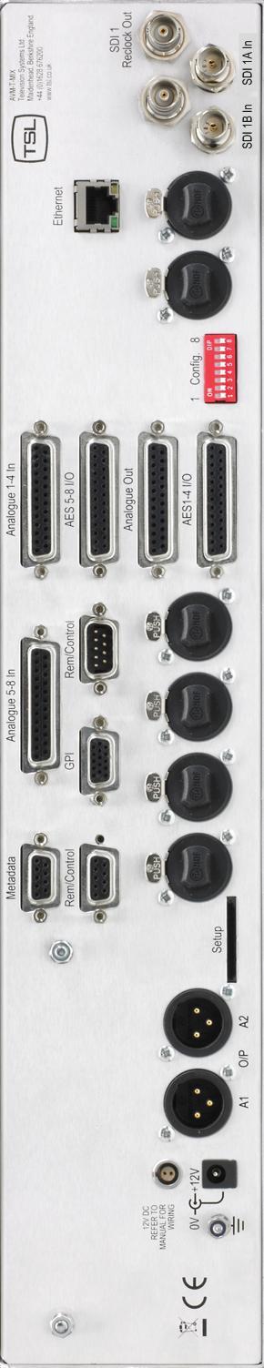
26 P a g e Physical Sources Touchmix has a total of 64 available physical sources available taken from SDI, AES and Analog connections, of which 48 are available at any given time. Each pair can be selected as a stereo or left only, right only input and routed to any physical output using the routing procedure described later in this document Choosing the active SDI input In previous versions of the Touchmix SD operating system the user could only access one of the physical SDI connectors and hence only a single video source could be wired to the box. In the latest release (from June 2014 onwards) the user is given access to an onboard 2x1 SDI switch and can choose to de-embed either of the physical SDI ports. An additional menu has been added to the product to enable this exclusive selection and can be accessed via the following commands Setup>SDI> SDI 1A or SDI 1B The selected SDI input chooses between physical BNC inputs labelled SDI 1 and SDI 2 however to avoid confusion with the 2SD product, the menu refers to the inputs as SDI 1A and 1B. Which input is chosen will be routed to the de-embedder and therefore available to the routing system exclusively for any given User Preset Physical Outputs As previously described in an earlier section regarding the default routing setup, the Touchmix comprises a total of 26 physical output ports. 16 AES channels (8 pairs) are presented on two D25 connectors, 8 analog channels are presented on a further D25 connector and an additional analog pair appears on two XLRs.


27 P a g e Routing Status Window The text box in the centre of the is a Routing Status indicator which provides a brief information summary of the highlighted route. The Routing Status Window indicates five fields of useful data; Output physical output pair Input physical or internal source Preset current active User Preset Lock Status Route is locked or unlocked Signal Pass Output will pass audio, data, Dolby or all formats The image below shows the Routing Status Window in the centre of the output screen where the 5.1 Variable buss has been assigned to analogue output pairs 1, 2 and 3. The User Preset is in this example is called Saturday Sport ; the route is Locked to prevent accidental re-assignment and the only signal format permissible is audio so that the surround speakers wired to the outputs are protected from data signals such as Dolby E Overview Menu Page The Overview Page is reached via the following path Setup>Output>Overview It comprises an XY routing system overview matrix as well as several command buttons that are used to set routing rules, default conditions and to lock routing selections to prevent misuse. Overview Table The overview table gives the user a visual summary of the current routing status of either the AES or Analog output routing status. By touching a pair or group of output channels on the overview table will display the system settings at the right hand side of the screen.


28 P a g e 28 The upper line of text in each button shows the physical output connection and the lower line shows the currently routed source Conditional Routing Rules The user can choose from the Overview Page the way that the selected output manages particular types of audio. By default the Touchmix is designed to mute all non-pcm Audio signals to prevent data (such as non-decoded Dolby E) from being accidentally routed to a loudspeaker. Using the conditional routing rules, any type of signal can be passed from source to destination without being muted Lock and Unlock Selection Once a critical routing selection has been made such as the assignment of 5.1 or Stereo variable monitoring to a pair of speakers via an analogue connection, the operator can lock the route to prevent accidental changes. The example shows a 5.1 Variable output that has been routed to analogue pairs 1,2,3 and locked to prevent re-assignment in error Set as Default Routing selections such as the assignment of 5.1 or Stereo Variable outputs to external loudspeakers are usually part of an installation and not changed once the Touchmix has been cabled. Set as Default enables the operator or technician to configure any Analogue or AES routing assignment from a single preset and then automatically copy the highlighted settings to all other user presets. The example below shows a 5.1 Var speaker assignment being set as a default to all 18 user presets. The routing assignments to Analogue 4L/R and the XLR connectors would not be written to all other presets as they are not highlighted. To set further default settings each group or pair to be set must be actioned in turn.

29 P a g e Routing System XY Crosspoint Map The matrix below describes the components of the XY routing system as a crosspoint map with the input sources to the Y Axis and the outputs to the X Axis. The right hand block of blue crosspoints denotes the bargraph routing selection to the mixers 1 and 2 and their resultant mix and monitor outputs can be seen towards the bottom left represented as routable sources. Although the majority of the routing infrastructure is freely assignable, you can see from the way that the 5.1 Mixer and Monitor busses are grouped that these sources can only be assigned to the first three pairs of any output AES or Analog output connector. This is one of very few restrictions imposed by the XY router system along with the fixed assignment of the stereo monitoring busses to the headphones and internal speakers.

30 P a g e User Preset and Snapshot Management Home Button and User Presets uses both internal and external User Preset memories to enhance usability, there are a total of 18 User Presets in local memory plus a Snapshot which is defined as HOME enabling operators to instantly revert to a default operational condition. A User Preset is defined as a Snapshot of a state of operation and includes the following parameters; MIXER 1 and MIXER 2 System XY Routing Configuration Channel Source Selection Channel Output Send Levels Channel Pan/Balance Channel Format Selection Input User Names Bargraph Configuration (including Scale, Ref, Zero etc.) GPI Mode Internal LS Mute Status External LS Mute Status Surround Mix Coefficient User Preset Name total of 18 Internal Memories can be backed up to a USB memory stick (front panel port) or SD Card (rear panel slot). Access to the USER PRESET/HOME menus is via the front panel HOME button User Presets SAVE Menu Holding down the HOME button for approximately 3 seconds accesses the SAVE menu. This menu page allows the operator to create and save snapshot memories, to backup the onboard memories to an external device or to configure the HOME preset. Set Home Pressing the Set Home button will automatically store the current operational configuration to the Home snapshot location.
, enter a name using the QWERTY keyboard (press Clear to remove the default name) and Save to store.")

31 P a g e 31 Set User Pressing the Set User button enables the operator to store the current operational configuration to any of the 18 internal memory locations. The following menu will appear; Simply select the desired internal memory location (User 1-18), enter a name using the QWERTY keyboard (press Clear to remove the default name) and Save to store. USB Save Pressing the USB Save button (only active when a USB Stick is inserted) enables the operator to backup all 18 internal memories to an external memory device. If an SD card is used via the rear panel then the will save to that device. If both a USB and an SD device are inserted simultaneously, the USB location will take precedence. The USB Save menu will ask the operator to confirm if they wish to replace an existing memory file before completing a backup.


32 P a g e User Presets Recall Menu Pressing the HOME button momentarily accesses the Recall menu. This menu page allows the operator to recall saved snapshot memories, to recall memories from an external device and to instantly recall the HOME snapshot. Recall Home Pressing the Recall button will automatically load the stored Home snapshot from internal memory. If no Home snapshot has been stored, the default shipping condition will be reloaded. Get User Pressing the Get User button enables the operator to load any of the 18 internal user presets from memory. User Presets are displayed in groups of 6, pages 1 to 3 are recalled via the More button. USB Load Pressing the USB Load button (only active when a USB Stick is inserted) enables the operator to restore all 18 internal memories from an external memory device.
33 P a g e Setup Menu Setup Menu includes options for different Scales, Reference Levels, Peak Hold, Input Naming, Output Routing, SDI Input Select, Mixer 1 mode and access to the Setup 2 Menu. By simply touching the appropriate button, individual sub menus are selected Meter Menu Pressing the Meter button accesses the bargraph scale options. is able to accurately replicate EBU Digital, EBU PPM, BBC PPM, DIN PPM, Nordic PPM and VU scales and ballistics. Please note that the selection of a scale type within the Meter screen will only be remembered by as a preset once the selection has been saved to internal memory using the User Preset commands described previously. This restriction enables the user to save preset conditions which work using different bargraph scales.

34 P a g e dbfs Menu The dbfs parameter selection can be used to alter the 0dBu reference level from between -12 and -24 dbfs Meter Peak Menu The Peak parameter selects the offset level between the Reference dbfs setting and the onset of Peak indication (the point where the bargraph changes colour to red) from between +1dB and +18dB Meter Zero Menu The Meter Peak selects between two modes of peak indication displayed on the channel bargraphs. The Bar Mode illuminates the bargraph as red once the audio level exceeds the peak value. In Block Mode the bargraph illuminates in yellow when the audio level exceeds the reference value and then red when it exceeds peak (as illustrated below).
35 P a g e Meter Hold Menu features a simple Peak Hold indicator which may be turned on and off using the Meter Hold Menu SDI Input Select A standard has two SDI inputs that can be switched into a single de-embedder as illustrated by the block diagram towards the front of this handbook. The screen printing on the rear of your is likely to denote the two SDI inputs as SDI1 and SDI2 respectively however the menu refers to them as SDI1A and SDI1B in order to differentiate between single and dual de-embedder product versions Mixer 1 Mode As previously described, Mixer 1 can operate in either Stereo or 5.1 modes. The mixer can be switched via the illustrated menu above Output Menu The function of the Router Output menu is described elsewhere in this handbook
36 P a g e Setup 2 Menu Setup 2 Menu includes options to protect User Presets, GPI Action, External and Internal Loudspeaker Mute, Surround Downmix Coefficients, Monitor Mode and to access the Software Management Menu User Save Menu The User Save Menu enables an Engineer or Technician to Lock or Unlock the User Preset management system onboard. In Locked mode a user is able to recall the Home Preset but unable to save or recall memories from internal or external (USB or SD Card) locations Monitor Mode The Monitor Mode Menu is used to select the audio sent to the internal speakers and headphone socket when T-MIX is not in Solo listening mode.
37 P a g e 37 In Default mode the operator would normally hear the output of whichever mixer is currently shown on the touchscreen. The user can choose to hear either Mixer 1 or Mixer 2 permanently regardless of the mixer under direct control GPI Menu The GPI Menu enables an Engineer or Technician to select whether GPI inputs respond to Latching or Momentary closures from external devices. The GPI connector can be used to Cut/Dim the internal and external Loudspeakers, recall Home preset and to recall User presets 1 to 7. The pin-out is described in Section 3.5. In Momentary Mode, Dim and Cut GPI's latch in a toggle manner, i.e. one closure to ground toggles the function ON; the next ground toggles it OFF. In an ON state; the GPI pin is driven low to allow an LED to be fed from the port. This LED drive is briefly pulsed high at about 100Hz to allow the port to be read whilst it is driving. The preset recall GPI s in Latching mode are mutually exclusive Internal / External Loudspeaker Mute The is designed to be used with either Internal or External Loudspeaker Systems. Users may wish to define User Preset conditions which associate the operation of the unit with internal speakers for in one state and external speakers in another. To facilitate this kind of hybrid operation the is equipped with individual Loudspeaker Mute buttons which can be configured with different functionality dependant upon their desired use and then saved to individual presets. In the event that is installed for use with external speakers only with the intention to mute the internal speakers, a DIP switch on the rear panel can be used to override the Internal LS Mute button in Setup 2 Menu.

 + (C -3dB); R= R + (Rs -3dB) + (C -3dB) When -6dB is selected, the 5.1 DMIX feature creates a stereo fold-down of the 5.")
38 P a g e Surround Mix Menu The S-MIX Menu provides a means to select the Downmix coefficient by which the Rear Surround Loudspeaker audio channels are added to the Front Left and Right when a Group/5.1 DMIX mode is selected. When -3dB is selected, the 5.1 DMIX feature creates a stereo fold-down of the 5.1 channels using the following algorithm; L= L + (Ls -3dB) + (C -3dB); R= R + (Rs -3dB) + (C -3dB) When -6dB is selected, the 5.1 DMIX feature creates a stereo fold-down of the 5.1 channels using the following algorithm; L= L + (Ls -6dB) + (C -3dB); R= R + (Rs -6dB) + (C -3dB) 2.14 Software Menu TSL is committed to providing customers with free life of product software updates as the features of evolve and any bugs are addressed. New code is made available via our reseller distribution channels and as a download from the TSL website. System Software may be updated by the owner via either the front panel USB Port (using a USB memory stick) or the rear panel SD Slot. Accessing the path Setup/ Setup2/ SWare the AVM-T- MIX will enter a menu page which reports the current software versions of the onboard Front Panel driver board (FP4), FPGA and PIC devices on the upper three information fields. If a memory device is inserted containing a software revision the three update fields will be displayed as illustrated below;

39 P a g e 39 In order to commence the upload sequence, simply press the UPDATE button and the FP4, FPGA, and PIC code will be loaded in order. Progress in indicated via the 0-100% scale. Once complete, will display a message confirming that the process has been successfully concluded prompting the user to perform a factory reset. To perform a factory reset it is necessary to remove power from the unit and then re-apply power whilst pressing the Home button until a message appears to confirm that Factory Default has been reloaded. Press Home once more and you will be able to operate with the new firmware active. The action of restoring Factory Default status will remove any stored memories from the. Please backup and restore memories from an external device if required. Please note that the UPGRADE sequence may take several minutes and may appear to stall it is important not to interrupt the process or to remove power from the device during a software upload as this may render the AMU unusable.
40 P a g e Connectivity and pin-out details uses industry standard connectivity wherever possible. The D25 connectivity used for analogue and AES I/O adopts a pinning convention commonly used for Yamaha Commercial Audio equipment and breakout cables are readily available at low cost from companies such as and many others. For unbalanced AES I/O connectivity an optional BNC breakout cable, CAB-D25-BNC, is available from TSL or your local reseller. When used in conjunction with, DIP switch 2 (AES Impedance) must be switched to the 75 ohm position. PLEASE NOTE THAT THE CONNECTIVITY INFORMATION PERTAINING TO ANALOGUE AND AES IN/OUT REFERS TO AS SHIPPED SYSTEM DEFAULTS. USING XY ROUTING FUNCTIONALITY IT IS POSSIBLE TO RECONFIGURE THE OUTPUT CONNECTIONS TO SUIT ANY USER PREFERENCE ALL PINOUT INFORMATION REMAINS THE SAME 3.1 Analogue XLR Connectors Stereo Variable Output (Monitor Buss) CONN PIN FUNCTION ANALOG 1 1 GND ANALOG IN+ ANALOG IN- ANALOG 2 1 GND ANALOG IN+ ANALOG IN-
41 P a g e Analogue Output Connector D25 Socket Pinout on unit, Plug (shown) on mating cable. D 25 SOCKET ON AMU AUDIO OUT PIN NO FUNCTION 1 A8+ (Var. Mon R) 14 A8- (Var. Mon R) 2 Ground 15 A7+ (Var. Mon L) 3 A7- (Var. Mon L) 16 Ground 4 A6+ (Fixed Mon R) 17 A6- (Fixed Mon R) 5 Ground 18 A5+ (Fixed Mon L) 6 A5- (Fixed Mon L) 19 Ground 7 A4+ (Fixed Mix 2R) 20 A4- (Fixed Mix 2R) 8 Ground 21 A3+ (Fixed Mix 2L) 9 A3- (Fixed Mix 2L) 22 Ground 10 A2+ (Fixed Mix 1R) 23 A2- (Fixed Mix 1R) 11 Ground 24 A1+ (Fixed Mix 1L) 12 A1- (Fixed Mix 1L) 25 Ground 13 N/C
42 P a g e Analogue Input Connectors 1-4 and 5-8 D25 Socket Pinout on unit, Plug on mating cable. D 25 SOCKET ON AMU AUDIO IN PIN NO FUNCTION 1 A4 (A8) R+ 14 A4 (A8) R+ 2 Ground 15 A4 (A8) L- 3 A4 (A8) L- 16 Ground 4 A3 (A7) R+ 17 A3 (A7) R- 5 Ground 18 A3 (A7) L+ 6 A3 (A7) L- 19 Ground 7 A2 (A6) R+ 20 A2 (A6) R- 8 Ground 21 A2 (A6) L+ 9 A2 (A6) L- 22 Ground 10 A1 (A5) R+ 23 A1 (A5) R- 11 Ground 24 A1 (A5) L+ 12 A1 (A5) L- 25 Ground 13 N/C
43 P a g e AES Input/Output Connectors 1-4 and 5-8 D25 Socket Pinout, Plug (shown) on mating cable. D 25 SOCKET ON AMU AES INPUTS/OUTPUTS PIN NO FUNCTION 1 Ch1&2 / 9&10 In Ch1&2 / 9&10 In 1-2 Ch3&4 / 11&12 In Ch3&4 / 11&12 In 2-3 Ch5&6 / 13&14 In Ch5&6 / 13&14 In 3-4 Ch7&8 / 15&16 In Ch7&8 / 15&16 In 4-5 Ch1&2 Fixed Mix 1 / 9&10 Out Ch1&2 Fixed Mix 1 / 9&10 Out 1-6 Ch3&4 Fixed Mix 2 / 11&12 Out Ch3&4 Fixed Mix 2 / 11&12 Out 2-7 Ch5&6 Fixed Mon / 13&14 Out Ch5&6 Fixed Mon / 13&14 Out 3-8 Ch7&8 Var. Mon. / 15&16 Out Ch7&8 Var. Mon. / 15&16 Out 4-9 N/C 22 Ground 10 Ground 23 Ground 11 N/C 24 Ground 12 Ground 25 Ground 13 Ground AES connectors may be wired using unbalanced terminations for SPDIF and 75R coaxial systems. Optional AES breakout cable CAB-D25-BNC-2 is available from TSL Sales ( ) and provides BNC Socket to D25 connectivity. Please note that when using with unbalanced AES audio connections that the 75/110 ohm DIP Switch must be selected prior to use. When using the D25 for unbalanced AES, AES XLR connectors 1 and 2 may not be used for balanced AES connectivity.
44 P a g e GPI Connector HD15 Socket. GPI pins are as follows: o Dim - pin 6 o Cut - pin1 o Home - pin 11 o User Preset 1 - pin 7 o User Preset 2 - pin 2 o User Preset 3 - pin 12 o User Preset 4 - pin 8 o User Preset 5 - pin 3 o User Preset 6 - pin 13 o User Preset 7 - pin 9 o +5V - pin 5 o 0V pin 15 o pins 4, 14, 10 unused at this time 3.6 Remote Control Connector/ RS D9 Socket This is wired for RS422 slave operation. D9 CONTROL 1 0V 6 0V 2 TX- 7 TX+ 3 RX+ 8 RX- 4 0V 9 0V 5 N/C 3.7 DIP switch configuration functions To be confirmed SWITCH FUNCTION 1 tbc 2 AES Impedance (75R Up/110R Dn) 3 Internal LS Mute (Mute Up/On Dn) 4 tbc 5 tbc 6 Analogue (XLR) Output (Fixed/Variable) 7 tbc 8 tbc
45 P a g e Notes There are no user adjustable assemblies/components within this unit. This unit requires rear support when rack mounted. In order to affect status changes of the unit using the rear DIP switch, the unit will require re powering before the changes take effect. Output analogue levels are adjustable over the following range: 0dBm = 0.775V into 600 i.e. 1mW power dissipation. 0dBu = 0.775V RMS = PPM 4. Shipping condition, -18 db ref 0FS = Typical European line up: Typical American line: 0dBu output. -18 dbu -20 dbu
AVM-T-MIX and AVM-T-MIX SD. Touch Series Audio Monitoring Unit. Handbook Version One
 Touch Series Audio Monitoring Unit Handbook Version One TSL Vanwall Road, Maidenhead, Berkshire, SL6 4UB - United Kingdom Telephone +44 (0)1628 676200 FAX +44 (0)1628 676299 P a g e 2 SAFETY Installation.
AMU2-2MHD+ Audio monitoring Unit
 AMU2-2MHD+ Audio monitoring Unit Handbook TSL Vanwall Road, Maidenhead, Berkshire, SL6 4UB Telephone +44 (0)1628 676200, FAX +44 (0)1628 676299 AMU2-2MHD+-6 1 ISSUE 5 SAFETY Installation. Unless otherwise
AVMU2-BHD+/3G Audio monitoring Unit
 AVMU2-BHD+/3G Audio monitoring Unit Handbook Television Systems Limited. Vanwall Road, Maidenhead, Berkshire, SL6 4UB Telephone +44 (0)1628 676200, FAX +44 (0)1628 676299 AVMU2-BHD+/3G 1 ISSUE 3 SAFETY
AMU1-BHD+ Audio monitoring Unit
 AMU1-BHD+ Audio monitoring Unit Handbook TSL Vanwall Road, Maidenhead, Berkshire, SL6 4UB Telephone +44 (0)1628 676200, FAX +44 (0)1628 676299 AMU1-BHD+-6 1 ISSUE 6 SAFETY Installation. Unless otherwise
AMU2-8HD+ & 3G Audio Monitoring Units Handbook TSL Vanwall Road, Maidenhead, Berkshire, SL6 4UB
 AMU2-8HD+ & 3G Audio Monitoring Units Handbook TSL Vanwall Road, Maidenhead, Berkshire, SL6 4UB Telephone +44 (0)1628 676200, FAX +44 (0)1628 676299 AMU2-8HD+/3G 1 Issue 1 SAFETY Installation. Unless otherwise
S1 Digital/Analogue Radio Broadcast Mixer September 2009
 S1 Digital/Analogue Radio Broadcast Mixer September 2009 www.sonifex.co.uk t: +44 (0)1933 650 700 f: +44 (0)1933 650 726 sales@sonifex.co.uk S1 Radio Digital/Analogue Broadcast Mixer Radio Broadcast Mixer
S1 Digital/Analogue Radio Broadcast Mixer
 S1 Digital/Analogue Radio Broadcast Mixer September 2009 www.sonifex.co.uk t: +44 (0)1933 650 700 f: +44 (0)1933 650 726 sales@sonifex.co.uk S1 Radio Digital/Analogue Broadcast Mixer Radio Broadcast Mixer
DRAFT RELEASE FOR BETA EVALUATION ONLY
 IPM-16 In-Picture Audio Metering User Manual DRAFT RELEASE FOR BETA EVALUATION ONLY Ver 0.2 April 2013 1 Contents Introduction...3 In Picture Audio Meter Displays...4 Installation...7 External Audio Board
BM- AV1- E16SHD Manual BM-AV1-E16SHD. 16 Channel Digital Audio Monitor. User s Guide. Version /01/2013. Version 2.
 Manual BM-AV1-E16SHD 16 Channel Digital Audio Monitor User s Guide Version 2.1 14/01/2013 Version 2.1 Page 1 BEL (Digital Audio) Ltd., has made every effort to ensure the accuracy of information contained
BM-A1-E16SHD V2.2. Manual BM-A1-E16SHD. 16 Channel Digital Audio Monitor. User s Guide. Page 1
 BM-A1-E16SHD V2.2 Manual BM-A1-E16SHD 16 Channel Digital Audio Monitor User s Guide Page 1 BEL (Digital Audio) Ltd., has made every effort to ensure the accuracy of information contained within this document,
S0 Radio Broadcasting Mixer. June catalogue. Manufacturers of audio & video products for radio & TV broadcasters
 S0 Radio Broadcasting Mixer June 2012 catalogue Manufacturers of audio & video products for radio & TV broadcasters S0 Radio Broadcasting Mixer A simple radio mixer for novice and professional users The
Model 6010 Four Channel 20-Bit Audio ADC Data Pack
 Model 6010 Four Channel 20-Bit Audio ADC Data Pack Revision 3.1 SW v1.0.0 This data pack provides detailed installation, configuration and operation information for the Model 6010 Four Channel 20-bit Audio
FWD8000 Dante enabled four wire box
 FWD8000 Dante enabled four wire box by CTP Systems Product warranty This unit is guaranteed for a period of one year from dispatch of the goods. This guarantee is a return to base warranty. In the unlikely
AES Channel Digital/Analog Audio Switcher/DA/Digital to Analog Converter
 Broadcast Devices, Inc. AES-408 8 Channel Digital/Analog Audio Switcher/DA/Digital to Analog Converter Technical Reference Manual Broadcast Devices, Inc. Tel. (914) 737-5032 Fax. (914) 736-6916 World Wide
Solid State Logic S O U N D V I S I O N
 Solid State Logic S O U N D V I S I O N SUPERANALOGUE X - R A C K Super-Analogue Outboard XR622 X-Rack Master Module User s Guide This documentation package contains the User s Guide for your new X-Rack
AES-402 Automatic Digital Audio Switcher/DA/Digital to Analog Converter
 Broadcast Devices, Inc. AES-402 Automatic Digital Audio Switcher/DA/Digital to Analog Converter Technical Reference Manual Broadcast Devices, Inc. Tel. (914) 737-5032 Fax. (914) 736-6916 World Wide Web:
Bel 2120B. Analogue/AES/SDI Shuffler. User s Guide Version /05/04
 Bel 2120B Analogue/AES/SDI Shuffler User s Guide Version 1.0 06/05/04 BEL (Digital Audio) Ltd. has made every effort to ensure the accuracy of information contained within this document which is nevertheless
IQBSFR AES/EBU Digital Audio ReMapper with Stereo Combiner and Gain Control
 IQBSFR AES/EBU Digital Audio ReMapper with Stereo Combiner and Gain Control C Module Description The IQBSFR accepts two isosynchronous AES/EBU inputs (4 input subframes). Digital audio sample rates of
AES-404 Digital Audio Switcher/DA/Digital to Analog Converter
 Broadcast Devices, Inc. AES-404 Digital Audio Switcher/DA/Digital to Analog Converter Technical Reference Manual Broadcast Devices, Inc. Tel. (914) 737-5032 Fax. (914) 736-6916 World Wide Web: www.broadcast-devices.com
Chapter 4 Signal Paths
 Chapter 4 Signal Paths The OXF-R3 system can be used to build a wide variety of signal paths with maximum flexibility from a basic default configuration. Creating configurations is simple. Signal paths
AM-4 Audio Monitor. Videoquip Research Limited 595 Middlefield Road, Unit #4 Scarborough, Ontario, Canada. MIV 3S2
 AM-4 Audio Monitor Videoquip Research Limited 595 Middlefield Road, Unit #4 Scarborough, Ontario, Canada. MIV 3S2 (416) 293-1042 1-888-293-1071 www.videoquip.com AM-4 4 channel Analog, AES3 Digital, SDI
ANALOG RADIO MIXER. Flexible. Affordable. Built To Last.
 ANALOG RADIO MIXER Flexible. Affordable. Built To Last. Audioarts AIR-4 A N A L O G R A D I O M I X E R At Audioarts, value engineering is straightforward: Define the features our customers require. Design
C8000. sync interface. External sync auto format sensing : AES, Word Clock, Video Reference
 features Standard sync module for a frame Internal sync @ 44.1 / 48 / 88.2 / 96kHz External sync auto format sensing : AES, Word Clock, Video Reference Video Reference : Black Burst (NTSC or PAL) Composite
User s Guide Version /01/2012
 BM- A2-16SHD 2012 BM-A2-16SHD 16 Channel Digital Audio Monitor User s Guide Version 1.0 01/01/2012 Version 1.0 Page 1 BEL (Digital Audio) Ltd., has made every effort to ensure the accuracy of information
FF DUAL FORMAT DJ MIXER USERS MANUAL
 FF - 4000 DUAL FORMAT DJ MIXER USERS MANUAL FF - 4000 INTRODUCTION The features and layout of the FF-4000 were determined in collaboration with leading loudspeaker manufacturers Funktion One, who canvassed
Model 5250 Five Channel Digital to Analog Video Converter Data Pack
 Model 5250 Five Channel Digital to Analog Video Converter Data Pack E NSEMBLE D E S I G N S Revision 3.1 SW v2.0.1 This data pack provides detailed installation, configuration and operation information
C8000. switch over & ducking
 features Automatic or manual Switch Over or Fail Over in case of input level loss. Ducking of a main stereo or surround sound signal by a line level microphone or by a pre recorded announcement / ad input.
GS-CU001M COMMENTATOR UNIT PRODUCT DETAILS
 GLENSOUND ELECTRONICS LTD GS-CU001M COMMENTATOR UNIT PRODUCT DETAILS 6 BROOKS PLACE, MAIDSTONE, KENT, ME1 1HE. ENGLAND. TEL: + (0) 1622 7020 Visit our Website at www.glensound.co.uk + (0) 1622 7662 FAX:
SoundField UPM-1 Stereo to 5.1 Converter
 Stereo to 5.1 Converter Version 2.0 CONTENTS: Safety Information - - - - - - - - - - 3 Introduction - - - - - - - - - - - 4 Example Application: Stadium Sports - - - - - - - 5-6 Controls - - - - - - -
Model 7600 HD/SD Embedder/ Disembedder Data Pack
 Model 7600 HD/SD Embedder/ Disembedder Data Pack E NSEMBLE D E S I G N S Revision 2.1 SW v2.0.1 This data pack provides detailed installation, configuration and operation information for the 7600 HD/SD
NV5100MC. Multi-channel, HD/SD master control switching and branding system. Master control switching and channel branding
 Master control switching and channel branding NV5100MC Multi-channel, HD/SD master control switching and branding system The NV5100MC master control switching system is ideal for national and regional
SAFETY. Unless otherwise stated TSL equipment may be installed at any angle or position within an operating temperature range of 5-30 C.
 SAFETY Installation. Unless otherwise stated TSL equipment may be installed at any angle or position within an operating temperature range of 5-30 C. All TSL equipment conforms to the EC Low Voltage Directive:
Kramer Electronics, Ltd. USER MANUAL. Models: VS-162AV, 16x16 Audio-Video Matrix Switcher VS-162AVRCA, 16x16 Audio-Video Matrix Switcher
 Kramer Electronics, Ltd. USER MANUAL Models: VS-162AV, 16x16 Audio-Video Matrix Switcher VS-162AVRCA, 16x16 Audio-Video Matrix Switcher Contents Contents 1 Introduction 1 2 Getting Started 1 3 Overview
Radio for Everyone...
 Radio for Everyone... P R O D U C T I O N O N A I R C O N S O L E Eight dual inputs Built in auto Silence detector 4 USB in/out stereo channels Play out USB control section included AES 3 digital program
X-Panda User s Guide
 X-Panda User s Guide This documentation is intended to be read along side the X-Panda Installation Guide which is available for download from our website www.solidstatelogic.com 82BXEM01A Contents Introduction
Models 5360 and 5365 Four Channel Analog to Digital Video Converters and Embedders Data Pack
 Models 5360 and 5365 Four Channel Analog to Digital Video Converters and Embedders Data Pack E NSEMBLE D E S I G N S Revision 1.3 SW v2.2.1 This data pack provides detailed installation, configuration
CM SERIES. 8 Channel Monitor / Crossover. 181 Bonetti Drive San Luis Obispo, CA ph: fax:
 CM SERIES 8 Channel Monitor / Crossover 181 Bonetti Drive San Luis Obispo, CA 93401 ph: 805-549-0161 fax: 805-549-0163 e-mail:usl@uslinc.com One Year Limited Warranty USL, Inc. warrants that each product
3G/HD/SD dual channel audio embedder/de-embedder
 3G/ dual channel audio embedder/de-embedder Dual channel audio embedder/de-embedder, with two independent video channels Being dual channel makes the audio embedder/de-embedder perfect for those pricesensitive
BM-A2-4SHD MKII. Ver Channel Digital Audio Monitor. User s Guide. Page 1
 BM-A2-4SHD MKII BM-A2-4SHD MKII 4 Channel Digital Audio Monitor User s Guide Page 1 BEL (Digital Audio) Ltd., has made every effort to ensure the accuracy of information contained within this document,
CLOCKAUDIO. MR88 Automatic Microphone Mixer. Version 4.2
 CLOCKAUDIO MR88 Automatic Microphone Mixer Version 4.2 Clockaudio Limited,22 Arnside Road WATERLOOVILLE Hampshire. UK Tel : +44 (0)2392 251193 Fax : +44 (0)2392 251201 Email : sales@clockaudio.co.uk CONTENTS
MODULAR I/O DIGITAL AUDIO CONSOLE. Flexible. Affordable. Built To Last.
 MODULAR I/O DIGITAL AUDIO CONSOLE Flexible. Affordable. Built To Last. 2 Audioarts X-12 Digital MODULAR I/O DIGITAL AUDIO CONSOLE There was a time when handling digital audio was an option. Not anymore.
RMX-44 & RMX-62 MIXING MATRIX. Installation & Operation Manual
 RMX-44 & RMX-6 MIXING MATRIX Installation & Operation Manual TABLE OF CONTENTS RMX-44 & RMX-6 INTRODUCTION... RMX-44 CALLOUTS... RMX-44 BLOCK DIAGRAM... RMX-6 CALLOUTS... 4 RMX-6 BLOCK DIAGRAM... 5 RMX-44
BSM Evolution USB - Compact ON AIR console. BSM Evolution USB. AEV On Air compact broadcast console
 BSM Evolution USB AEV On Air compact broadcast console 1 Guarantee The equipment is warranted for a period of 2 years from the date of invoice (ex-works). The warranty does not cover faults provoked by
Model 50 Central Controller, Model 51 Control Console, and Related Components. User Guide
 Model 50 Central Controller, Model 51 Control Console, and Related Components User Guide Issue 5, June 2002 This User Guide is applicable for systems consisting of: Model 50, serial number M50-00385 to
SE GPI 27 SE-2200
 Contents Warranty... 3 Disposal... 3 Packing List... 4 Connection of SE-2200... 4 Main Unit Front Panel... 5 Main Unit - Rear Panel... 5 Rear Panel Connections... 6 Control Panel... 8 Keyboard Controls...
DSA-1. The Prism Sound DSA-1 is a hand-held AES/EBU Signal Analyzer and Generator.
 DSA-1 The Prism Sound DSA-1 is a hand-held AES/EBU Signal Analyzer and Generator. The DSA-1 is an invaluable trouble-shooting tool for digital audio equipment and installations. It is unique as a handportable,
C8491 C8000 1/17. digital audio modular processing system. 3G/HD/SD-SDI DSP 4/8/16 audio channels. features. block diagram
 features 4 / 8 / 16 channel LevelMagic2 SDI-DSP with level or loudness (ITU-BS.1770-1/ ITU-BS.1770-2, EBU R128) control 16 channel 3G/HD/SD-SDI de-embedder 16 in 16 de-embedder matrix 16 channel 3G/HD/SD-SDI
PHASE HL SEL 1 HL SEL 2 EXT MONITOR ELAN ELAN ELAN ELAN MLM-201 HLM-201 HLM-201 TBM-201 MLM-201 GAIN GAIN GAIN LEFT GAIN RIGHT SELECT SELECT SELECT
 Audio Promotional Information "Kestrel-12" and "Kestrel-16" Modular Dual Channel Stereo "On-Air" Mixer "Kestrel-12" "KESTREL-12" HL SEL 1 HL SEL 2 EXT MITOR VU O'LOAD PHASE VU VU AUDIO AIR DELAY DUMP TLM-201
User Guide. FFFA WORD CLOCK SECONDARY PRIMARY NETWORK PRIMARY CLOCK SOURCE WORD CLOCK. SAMPLE RATE 44.
 User Guide NETWORK PRIMARY SAMPLE RATE 44.1 khz 2 CLOCK SOURCE WORD CLOCK DARS SECONDARY 48 khz 4 1-2 3-4 5-6 7-8 9-10 11-12 13-14 15-16 PUT 1-2 POWER LOCKED PULL UP/DOWN PUT 9-10 TERNAL PSU A PSU B NETWORK
CDM10: Channel USB Mixer. Item ref: UK User Manual
 CDM10:4 19 4 Channel USB Mixer Item ref: 171.135UK User Manual Caution: Please read this manual carefully before operating Damage caused by misuse is not covered by the warranty Introduction Thank you
MX-AIR : THE PERFECT TOOL FOR SWITCHING AUDIO & VIDEO
 MX-AIR : THE PERFECT TOOL FOR SWITCHING AUDIO & VIDEO The MX-AIR is an advanced Video and Audio follow Switcher. Housed in a robust and compact frame it can process 8 SDI video different sources with embedded
OWNERS MANUAL LUNATEC V3 MICROPHONE PREAMPLIFIER AND A/D CONVERTER
 OWNERS MANUAL LUNATEC V3 MICROPHONE PREAMPLIFIER AND A/D CONVERTER LUNATEC 35 +48 35 +48 30 40 30 40 0 25 45 25 45 3 192 1 1 6 176.4 20 50 20 50 9 96 12 PEAK 88.2 55 55 RESET 48 10 60 2 10 60 2 21 44.1
BM-A1-2SHD MKII. Ver1.1 BM-A1-2SHD MKII. 2 Channel Digital Audio Monitor. User s Guide. Page 1
 BM-A1-2SHD MKII BM-A1-2SHD MKII 2 Channel Digital Audio Monitor User s Guide Page 1 BEL (Digital Audio) Ltd., has made every effort to ensure the accuracy of information contained within this document,
System Interface Unit SIU-100/100T
 System Interface Unit /100T Since its introduction, the Digital Mixer has opened up an entirely new set of opportunities for affordable PA and sound-recording applications. Recognizing the ever-increasing
Ultra-ViewRF 8HD Director Monitor. User Operation Manual
 Ultra-ViewRF 8HD 5.8GHz Wireless Director Monitor User Operation Manual 17.1.2013 v2_7 Video Equipment Rentals - VER 912 Ruberta Avenue Glendale, CA 91201 - U.S.A. Office 818-956-1444 Table of Contents
DLM471S-5.1 MULTICHANNEL AUDIO LEVEL MASTER OPERATION MANUAL IB B. (Mounted in RMS400 Rack Mount & Power Supply) (One of 4 Typical Cards)
 (One of 4 Typical Cards)") DLM471S-5.1 (Mounted in RMS400 Rack Mount & Power Supply) MULTICHANNEL AUDIO LEVEL MASTER (One of 4 Typical Cards) OPERATION MANUAL IB6432-02B TABLE OF CONTENTS PAGE 1.0 GENERAL DESCRIPTION 2 2.0 INSTALLATION
DLM471S-5.1 (Mounted in RMS400 Rack Mount & Power Supply) MULTICHANNEL AUDIO LEVEL MASTER (One of 4 Typical Cards) OPERATION MANUAL IB6432-02B TABLE OF CONTENTS PAGE 1.0 GENERAL DESCRIPTION 2 2.0 INSTALLATION
owner s manual manual Rev G main unit firmware Rev 1.08 RCU firmware Rev 1.07 all contents Grace Design/ Lunatec LLC
 manual Rev G main unit firmware Rev 1.08 RCU firmware Rev 1.07 all contents Grace Design/ Lunatec LLC Welcome! Thanks for purchasing the Grace Design m906 high fidelity 5.1 monitoring system. We build
The Dangerous Music D-Box user s operating guide
 The Dangerous Music D-Box user s operating guide Thank you for choosing products from the exciting line of Dangerous Music recording equipment. Many years of dependable and trouble-free service can be
CEDAR Series. To learn more about Ogden CEDAR series signal processing platform and modular products, please visit
 CEDAR Series The CEDAR platform has been designed to address the requirements of numerous signal processing modules. Easily-installed components simplify maintenance and upgrade. To learn more about Ogden
Table of Contents FCC COMPLIANCE STATEMENT... 4 WARNINGS AND PRECAUTIONS... 4 WARRANTY... 5 STANDARD WARRANTY... 5 TWO YEAR WARRANTY... 5 DISPOSAL...
 1 Table of Contents FCC COMPLIANCE STATEMENT... 4 WARNINGS AND PRECAUTIONS... 4 WARRANTY... 5 STANDARD WARRANTY... 5 TWO YEAR WARRANTY... 5 DISPOSAL... 6 1. INTRODUCTION... 7 FEATURES... 7 2. CONNECTIONS
MIDAS Venice Pin-Assignments Page 1 / 3 Mono-Channel-PCB Stereo- / Master - PCB CN 1 circuit diagram number CN 6 circuit diagram number CN
 MIDAS Venice Pin-Assignments Page 1 / 3 Mono-Channel-PCB 81346 Stereo- / Master - PCB 82230 CN 1 circuit diagram number CN 6 circuit diagram number CN 7 circuit diagram number CN 1 circuit diagram number
DIGITAL SWITCHERS 2100 SERIES
 DIGITAL SWITCHERS 00 SERIES HIGH PERFORMANCE DIGITAL ROUTING OPERATORS MANUAL Includes Module and Frame Information for: AUDIO DAS- DAS-88 DAS-66 VIDEO DVS- DVS-8 DVS-6 DVM-66 DVS-66 SIGMA ELECTRONICS,
Element 78 MPE-200. by Summit Audio. Guide To Operations. for software version 1.23
 Element 78 MPE-200 by Summit Audio Guide To Operations for software version 1.23 TABLE OF CONTENTS IMPORTANT SAFETY AND GROUNDING INSTRUCTIONS COVER 1. UNPACKING AND CONNECTING...3 AUDIO CONNECTIONS...4
HDMI 1 HDMI 2 HDMI 3 HDMI
 Mode HDMI 1 HDMI 2 HDMI 3 HDMI 4 Format Menu Up Enter IR Dual Switcher Power Embed L/R In HDMI 1 HDMI 2 HDMI 3 HDMI 4 VGA YPbPr AV Down Esc MFP72 User Manual Thank you for purchasing this product. For
SIGNAL PROCESSOR. Operation Manual
 SIGNAL PROCESSOR Operation Manual Using the PDF manual From the Contents on page 2, click on the desired topic to automatically jump to the corresponding page. Click on a link in this manual to jump to
Neve :2 Summing Mixer User Manual
 Neve 8816 16:2 Summing Mixer User Manual 527-361 Issue 5 AMS NEVE Billington Road Burnley Lancs BB11 5UB England Phone +44 (0)1282 457011 Fax: +44 (0)1282 417282 info@ams-neve.com www.ams-neve.com www.neve.eu
SIGNAL PROCESSOR. Operation Manual
 SIGNAL PROCESSOR Operation Manual Using the PDF manual From the Contents on page 2, click on the desired topic to automatically jump to the corresponding page. Click on a link in this manual to jump to
M A S T E R S E C T I O N. User Manual
 M A S T E R S E C T I O N User Manual Version 1.02: July 2007 Contents. Safety Information.... 3 Welcome.... 4 Connections.... 5 A Basic Set-up 5 Setting Up.... 7 Adjusting Input Levels 7 Taking Account
LDM24 Digital Monitoring Adapter Manual
 Electronics LDM24 Digital Monitoring Adapter Manual LDM24 Manual - Issue 1 January 1999 Lindos Electronics Issue 1, January 1999 Lindos Electronics 1999 The Lindos LDM24 Digital Monitoring Adapter is a
CL1200 MIXING CONSOLE. Item ref: UK User Manual
 CL1200 MIXING CONSOLE Item ref: 170.881UK User Manual Caution: Please read this manual carefully before operating Damage caused by misuse is not covered by the warranty Introduction Thank you for choosing
Recording to Tape (Analogue or Digital)...10
...10") c o n t e n t s DUAL MIC-PRE Green Dual Mic Pre (introduction).............................4 Section (i): Setting Up Power Connections...........................................4 Power Supply................................................5
c o n t e n t s DUAL MIC-PRE Green Dual Mic Pre (introduction).............................4 Section (i): Setting Up Power Connections...........................................4 Power Supply................................................5
for Surround Model 76DA Central Controller and Model 77 Control Console User Guide Issue 2, April 2011
 Model 76DA Central Controller and Model 77 Control Console User Guide Issue 2, April 2011 This User Guide is applicable for systems consisting of: Model 76DA: serial number M76DA-00151 and later with software
GS-GC5K ISDN Commentary Mixer South African Broadcasting User Notes
 GS-GC5K ISDN Commentary Mixer South African Broadcasting User Notes Who Are Glensound? Glensound have been designing and building broadcast equipment since 1966. The founder, Len Davis, is an ex BBC engineer,
Natural-sounding telephone audio... Hybrids
 Natural-sounding telephone audio... Hybrids ... for broadcast, conferencing and public address About Comrex DH Series Digital Telephone Hybrids When you want to present, broadcast, or record a telephone
T L Audio. User Manual C1 VALVE COMPRESSOR. Tony Larking Professional Sales Limited, Letchworth, England.
 T L Audio User Manual C1 VALVE COMPRESSOR Tony Larking Professional Sales Limited, Letchworth, England. Tel: 01462 490600. International +44 1462 490600. Fax: 01462 490700. International +44 1462 490700.
User Guide FA
 User Guide ON FA9096-06 www.focusrite.com CONTENTS About this User Guide...3 Box Contents................................................................3 INTRODUCTION... 4 INSTALLATION GUIDE... 5 RedNet
3G, HD & SD-SDI. Embedders & De-Embedders. Catalogue
 3G, HD & SD- s & De-s 2016 Catalogue & Video Interfaces - Video s & De-s 3G, HD & SD- s & De-s Still in the familiar Redbox chassis offering rackmounting as standard and a universal AC power supply, these
1608-II and 2448 Recording Console Operator s Manual
 Recording Console Operator s Manual Written for Automated Processes ncorporated by Dan Pfeifer Rev. 18-12-30 2018 8301 Patuxent Range Road Jessup, MD 20794 USA 301-776-7879 http://www.apiaudio.com Table
National Park Service Photo. Utah 400 Series 1. Digital Routing Switcher.
 National Park Service Photo Utah 400 Series 1 Digital Routing Switcher Utah Scientific has been involved in the design and manufacture of routing switchers for audio and video signals for over thirty years.
Master Section
 Master Section -18 9 9 18 VU VU The Master section of the Custom Series 75 is host to two linkable (and externally patchable) mono 2254 compressors, the 281 Channel Module routing options, eight Groups,
12 Channel Media Splitter MS12 Mk2 User manual
 12 Channel Media Splitter MS12 Mk2 User manual 01. 12 Channel Media Splitter MS12 Mk2 An audio distribution amplifier primarily designed to feed multiple ENG cameras from a single lectern microphone at
3GSDI Audio Embedder
 1080P 3GSDI Audio Embedder GEF-SDI-AUDE User Manual www.gefenpro.com ASKING FOR ASSISTANCE Technical Support: Telephone (818) 772-9100 (800) 545-6900 Fax (818) 772-9120 Technical Support Hours: 8:00 AM
AMPx-D8 Series AMP1-D8DA AMP1-D8MDA-3G AMP2-D8DA AMP2-D8MDA-3G
 AMPx-D8 Series AMP1-D8DA AMP1-D8MDA-3G AMP2-D8DA AMP2-D8MDA-3G 2RU, Dolby, Multi-Format, Analog/ Digital Audio Monitors User Guide Part Number 821077, Revision B 2011 Wohler Technologies, Inc. All rights
Model 7130 HD Downconverter and Distribution Amplifier Data Pack
 Model 7130 HD Downconverter and Distribution Amplifier Data Pack E NSEMBLE D E S I G N S Revision 1.0 SW v1.0 www.ensembledesigns.com 7130-1 Contents MODULE OVERVIEW 3 Audio Handling 3 Control 3 Metadata
DM1624, DM1612, DM812
 Installation Guide Hardware and Software DM Series Digital Processors models DM1624, DM1612, DM812 LECTROSONICS, INC. 1 Installation Specific Information Only This guide covers only installation related
NV5128-MC MULTI CHANNEL MASTER CONTROL SWITCHER
 NV5128-MC MULTI CHANNEL MASTER CONTROL SWITCHER An Integrated Platform for Multi Channel Master Control and Routing Cost Saving Design If you're concerned about the cost of converting your station to digital,
Connevans.info. DeafEquipment.co.uk. This product may be purchased from Connevans Limited secure online store at
 Connevans.info Solutions to improve the quality of life Offering you choice Helping you choose This product may be purchased from Connevans Limited secure online store at www.deafequipment.co.uk DeafEquipment.co.uk
owner s manual manual Rev H m904 firmware Rev 1.04 m904 RCU firmware Rev 1.05 all contents Grace Design/ Lunatec LLC
 owner s manual manual Rev H m904 firmware Rev 1.04 m904 RCU firmware Rev 1.05 all contents Grace Design/ Lunatec LLC Welcome Thanks for purchasing the Grace Design m904 high fidelity monitoring system.
When going digital is this easy, why stay analogue?
 Soundcraft, Harman International Industries Ltd., Cranborne House, Cranborne Road, Potters Bar, Hertfordshire EN6 3JN, UK T: +44 (0)1707 665000 F: +44 (0)1707 660742 E: soundcraft.info@harmancom Soundcraft
for Surround Model 76DA Central Controller and Model 77 Control Console User Guide Issue 7, May 2013
 Model 76DA Central Controller and Model 77 Control Console User Guide Issue 7, May 2013 This User Guide is applicable for systems consisting of: Model 76DA: serial number M76DA-00151 and later with software
AxumVideo 0 intro. Now that you have connected the different AXUM system parts, you are ready to configure the system according to your own needs.
 AxumVideo 0 intro Now that you have connected the different AXUM system parts, you are ready to configure the system according to your own needs. On the left we see the RACK unit and on the right we see
C8188 C8000 1/10. digital audio modular processing system. 4 Channel AES/EBU I/O. features. block diagram. 4 balanced AES inputs
 features 4 balanced AES inputs Input Sample Rate Converters (SRC) 4 balanced AES outputs Relay bypass for pairs of I/Os Relay wait time after power up Master mode (clock master for the frame) 25pin Sub-D,
CHAPTER 3 AUDIO MIXER DIGITAL AUDIO PRODUCTION [IP3038PA]
![CHAPTER 3 AUDIO MIXER DIGITAL AUDIO PRODUCTION [IP3038PA]](/thumbs/73/68858919.jpg "CHAPTER 3 AUDIO MIXER DIGITAL AUDIO PRODUCTION [IP3038PA]") CHAPTER 3 AUDIO MIXER DIGITAL AUDIO PRODUCTION [IP3038PA] Learning Objectives By the end of this chapter, students should be able to: 1 State the function of the audio mixer in the sound studio. 2 Explain
CHAPTER 3 AUDIO MIXER DIGITAL AUDIO PRODUCTION [IP3038PA] Learning Objectives By the end of this chapter, students should be able to: 1 State the function of the audio mixer in the sound studio. 2 Explain
SAFETY PRECAUTIONS. The SPIRIT FX16 mixer must only be connected through the Power Supply supplied:
 INTRODUCTION Thank you for purchasing an FX16 mixer, brought to you with pride by the SPIRIT team of Andy, Colin, Chris, Simon, Mukesh, Graham, Martin, Paul, Tony and Peter, with the support of many others
FS1-X. Quick Start Guide. Overview. Frame Rate Conversion Option. Two Video Processors. Two Operating Modes
 FS1-X Quick Start Guide Overview Matching up and synchronizing disparate video and audio formats is a critical part of any broadcast, mobile or post-production environment. Within its compact 1RU chassis,
for Surround Model 76D Central Controller and Model 77 Control Console User Guide Issue 3, September 2010
 Model 76D Central Controller and Model 77 Control Console User Guide Issue 3, September 2010 This User Guide is applicable for systems consisting of: Model 76D: serial number M76D-00201 and later with
Model 4455 ASI Serial Digital Protection Switch Data Pack
 Model 4455 ASI Serial Digital Protection Switch Data Pack Revision 1.5 SW v2.2.11 This data pack provides detailed installation, configuration and operation information for the 4455 ASI Serial Digital
Intelligent Security and Fire Ltd
 User Manual Product ranges covered by this manual Vi-P14 Vi-P14A Document Reference Date Firmware Vi-Q4C1 Viq601a.doc 26/11/2009 From Viq001a21 Videoswitch Telephone 01252-851510 Ocean House, Redfields
V pro8 QUICK START GUIDE
 QUICK START GUIDE Welcome to your V pro8 FIRST STEPS POWERING ON CONNECTING YOUR COMPUTER Thank you for buying the Lawo V pro8, a true high-quality product developed and manufactured in Rastatt, Germany.
EEG A1452 SCTE-104 Inserter Frame Card
 EEG A1452 SCTE-104 Inserter Frame Card Product Manual EEG Enterprises, Inc. 586 Main Street Farmingdale, New York 11735 TEL: (516) 293-7472 FAX: (516) 293-7417 Copyright EEG Enterprises, Inc. 2017 All