Model R177M and R177S Baseband Switch
|
|
|
- Juliet McKenzie
- 6 years ago
- Views:
Transcription

1 Model R177M and R177S Baseband Switch Installation Guide P/N Monroe Electronics 100 Housel Ave Lyndonville NY fax
2 Table of Contents Warranty 3 General Description 4 Specifications 5 Installation 6 Operation & Adjustments 7 Master/Slave Audio Connections 8 Program Source Connections 9 Baseband System Connections 10 Specifications subject to change without notice. P/N Rev A 5/15/02 2
3 WARRANTY Monroe Electronics, Inc. warrants to the owners, each instrument and sub-assembly manufactured by them to be free from defects in material and workmanship for a period of one year after shipment from factory. This warranty is applicable to the original purchaser only. Liability under this warranty is limited to service, adjustment or replacement of defective parts (other than fuses or batteries) on any instrument or sub-assembly returned to the factory for this purpose, transportation charges prepaid. This warranty does not apply to instruments or sub-assemblies subjected to abuse, abnormal operating conditions, or unauthorized repair or modification. Since Monroe Electronics, Inc. has no control over conditions of use; no warranty is made, or implied as to the suitability of our product for the customer's intended use. THE WARRANTY SET FORTH IN THIS ARTICLE IS EXCLUSIVE AND IN LIEU OF ALL OTHER WARRANTIES AND REPRESENTATIONS, EXPRESSED, IMPLIED OR STATUTORY INCLUDING, BUT NOT LIMITED TO THE IMPLIED WARRANTIES OF MERCHANTABILITY AND FITNESS. Except for obligations expressly undertaken by Monroe Electronics, in this warranty, Owner hereby waives and releases all rights, claims and remedies with respect to any and all warranties, express, implied or statutory (including without limitation, the implied warranties of merchantability and fitness), and including but without being limited to any obligation of Monroe Electronics with respect to incidental or consequential damages, or damages for loss of use. No agreement or understanding varying or extending the warranty will be binding upon Monroe Electronics unless in writing signed by a duly authorized representative of Monroe Electronics. In the event of a breach of the foregoing warranty, the liability of Monroe Electronics shall be limited to repairing or replacing the non-conforming goods and/or defective work, and in accordance with the foregoing; Monroe Electronics shall not be liable for any other damages, either direct or consequential. RETURN TO FACTORY POLICY: Materials returned to Monroe must have a Return Material Authorization number. To obtain a RMA number, contact our A/V Switching & Control Customer Service at or fax Customers have 30 days to determine that the product ordered fills their need and performs as described in Monroe s literature. Units returned for approved repair or credit, must be in the original packaging including all parts and paperwork plus be in very good physical condition. If not, the customer is billed the cost to refurbish the unit and for missing accessories and merchandise. No products may be returned for exchange or credit after 12 months of the shipment date. Monroe reserves the right to repair or replace units under warranty. 3
4 General Description Developed especially for the small cable operator, the model R177 offers inexpensive baseband switching for full screen and audio replacement in full compliance with FCC EAS requirements. Available in two configurations; Master (R177M) and Slave Monaural (R177S), both units provide amplification and switching of baseband audio follow video signals and allow the insertion of audio and video from an EAS control system into all the channels at a cable headend. When the proper alert codes are received by the EAS system, baseband video signals from each channel are switched from the programs they normally show to the alarm video provided by a character generator. Audio is similarly switched. When the EAS alert (or test) has concluded the unit(s) switch back to the program audio and video. Switching of the audio signals and video signals can be done independently if desired. Each unit has eight audio and video switches. EAS Audio and Video signals are buffered with adjustable ±3 db amplifiers for isolation and signal quality. Individual test switches allow separate testing of the audio and video relays in the unit, allowing less intrusive testing when desired. The modularity of the design, with 8 complete switch pairs per unit, allows the operator to mount the unit where he can minimize cable runs and complexity. Mounting it on the rear of the equipment rack saves valuable space for other uses. R177M The Model R177M Master Baseband Switch is the master unit and provides balanced stereo audio follow baseband video switching on a contact closure. The baseband video, audio signals, and control signals are looped through to supply succeeding units. High quality and long life RF and Audio switching relays ensure low loss and high isolation for reliable system performance. Control of this unit to switch audio, video, or both, passes through to any succeeding units for EAS alarm switching. The R177M can also be used as a stereo slave unit. R177S The Model R177S Stereo Baseband Switch operates as a slave unit with the Model R177M unit. It provides balanced monaural audio and wide bandwidth baseband video switching. The loop through video and audio signals are internally buffered with an audio gain adjustment. Switching relays provide isolation and signal handling capabilities to satisfy any user requirements. 4
5 Specifications Video Input Level: Video Frequency Response: Video Output Level for Loop through: Video Connectors: Audio Input Level: Audio Frequency Response: Master Audio Output Level for loop through: Audio Connectors: Master Switch Control Inputs: Slave Switching (or Master used as Slave) 1 V p~p, (75) 0 to 40 MHz, -3 db 1 V p~p, 0 db buffered 75 F connectors 0 db, ~.7 volts p~p nominal 0 to 30 KHz, -3 db, 600 Term In/Out Adjustable, ± 3 db nominally.7 volts p~p into 600 s buffered Detachable screw terminals Contact closure to Ground. Independent Video and Audio contact closure to or recessed push buttons on panel DC voltage on Audio Lines, or push buttons for testing Audio/Video for that unit only. Power Requirements:* 16 VAC 50/60 Hz, ± 10%, ½ A AC Physical Size: Weight: 19.0 W x 3.5 H x 5.0 D 2 lbs. *12 VAC power supplies will work provided the supply is stable at 12V under low line conditions. However, 16 VAC supplies are provided and are recommended for optimal reliability. 5
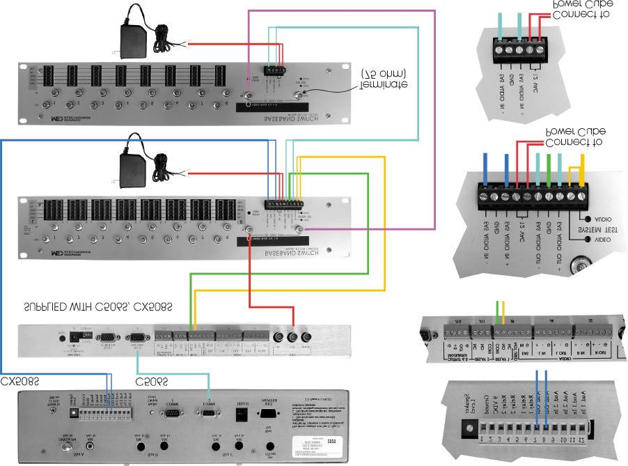
6 Installation The R177 units are designed to mount on the rear of a standard 19-inch equipment rack. Mount the Master Stereo unit, R177M, onto the equipment rack near the audio signal sources requiring stereo switching. Mount the Slave Monaural units, R177S, onto to the equipment rack near the signal sources they will be switching. Connect the wires from the power supplies to each unit, 12 or 16 VAC (Refer to * note on page 4.) on the screw terminal header. No specific polarity needs to be observed when connecting the first power supply, however, all subsequent supplies must be connected with the same wire orientation as the first supply. Connect the Audio Outputs from the MIP 921e to the Audio Inputs + and on the screw terminal header of the Master unit. A Chassis Ground connection is supplied for a shield wire. Connect the EAS Audio Out +,, and connections on the screw terminal header of the Master unit to the EAS Audio In of the first Slave Monaural unit as detailed in Figure 1. If using a Master unit as a Slave Stereo unit refer to Figure 2 on the following page. Connect all remaining Slave units to each other in the same manner, as indicated in Figure 1 or 2 on the following page. Connect the CEMS 0500 Character Generator Video Out to the EAS Video Loop input on the Master unit. Connect the Video Loop Output to the first Slave unit Video Loop Input. For all subsequent Slave units in the chain, connect the Output from the preceding unit to the Input of the unit being added. Connect the program audio source inputs to the left and right Audio inputs for each switch set as labeled on the panel. Connect the Video Inputs and Outputs in the same manner. Refer to Figure 3 on page 7. To complete the connection 600 Ω terminators or resistors must be installed across the and terminals on the Master unit and also across the EAS Audio + and terminals on the last Slave unit in the chain. Refer to Figures 1 and 2 on the following page. Tie the VIDEO and AUDIO terminals at the end of the R-177M terminal strip together and connect to the CEMS 0500 Character Generator at RELAY 1 NO. Connect on the terminal strip to RELAY 1 COM on the CEMS
7 Operation and Adjustments Plug in all power supplies upon completion of all wiring. Verify operation by pressing the Audio and Video Test pushbuttons recessed in the panel. All relays should switch for either Video or Audio subject to which pushbutton has been pressed. Upon verifying operation, set the Audio Input from the EAS alarm source to 1 V p ~ p, maximum. Set the Video Input from the EAS alarm source to 1 V p ~ p, maximum. Check the outputs to the Audio and Video switches. Adjust the Audio Gain potentiometer to obtain an output of the same level as the input. Adjust the two Video Gain potentiometers in the same manner. 7
8 Master/Slave EAS Audio Connections Master Slave #1 Last Slave EAS Audio IN Audio Input 600Ω 600Ω Termination EAS Audio Out EAS Audio Out + Figure 1 Master/Slave EAS Audio Connections with a Master used as a Slave Master Slave #1 Master as Slave Last Slave Audio Input 600Ω 600Ω Termination EAS Audio Out EAS Audio Out EAS Audio Out + EAS Audio Out + Figure 2 8
9 Program Source to Controlling R177 Master is shown. For Slave Monaural connections, a single connector is provided. For connections to a Master used as a Slave, connect to left side connectors only. One set of Audio/Video switching connections are shown. All subsequent connections should be made in the same manner. Video Out Video In L R Audio Out - Audio Out + Audio In - Audio In + Audio In + Audio In - Audio Out + Audio Out - Figure 3
10
Instruction Manual. Series 3000 Model R-165A. Audio/Video IF/RF Relay Panel. CATV Switching and Control
 Series 3000 Model R-165A Audio/Video IF/RF Relay Panel Instruction Manual CATV Switching and Control 585-765-2254 fax 585-765-9330 100 Housel Ave. Lyndonville NY 14098 www.monroe-electronics.com Table
INSTRUCTION MANUAL MODEL 2710 SUBCARRIER DEMODULATOR
 INSTRUCTION MANUAL MODEL 2710 SUBCARRIER DEMODULATOR Data, drawings, and other material contained herein are proprietary to Cross Technologies, Inc., and may not be reproduced or duplicated in any form
Model PSKIT-H540 Ultrasonic Power Supply Kit 40 khz 500 Watts
 Model PSKIT-H540 Ultrasonic Power Supply Kit 40 khz 500 Watts INSTRUCTION MANUAL Sonics & Materials, Inc. 53 Church Hill Road Newtown, CT 06470 USA 203.270.4600 800.745.1105 203.270.4610 fax www.sonics.com
INSTALLATION AND OPERATION MANUAL
 INSTALLATION AND OPERATION MANUAL for the Broadcast Tools 6 x 1 Six Input, Single Output Stereo Switcher/Router Broadcast Tools is a registered trademark of Copyright 1994-2002 by All rights reserved.
Instruction Manual Model BlockUpconverter
 Instruction Manual Model 2115-55 BlockUpconverter June 2009 - Rev. 0 MODEL 2115 UPCONVERTER CROSS TECHNOLOGIES INC. EXT 10MHZ ALARM POWER Data, drawings, and other material contained herein are proprietary
Instruction Manual Model # Block Upconverter
 Instruction Manual Model 2115-278# Block Upconverter August 2018, Rev. A MODEL 2115 UPCONVERTER CROSS TECHNOLOGIES INC. EXT 10MHZ ALARM POWER Data, drawings, and other material contained herein are proprietary
Model /29S RF Splitter
 Instruction Manual Model 1584-29/29S RF Splitter March 2013, Rev. 0 LNB VOLTAGE A B MODEL 1584 COMBINER CROSS TECHNOLOGIES INC. GND+DC ON Data, drawings, and other material contained herein are proprietary
UTP ACTIVE TRANSCEIVER HUB
 VI6116 UTP ACTIVE TRANSCEIVER HUB USER S MANUAL 7810 Trade Street, Suite 100 San Diego, CA 92121, U.S.A. Phone: (858) 484-5209 Fax: (858) 484-1205 1 1. Introduction The Vigitron VI6116 is a 16 port active
Installation and Operation Manual. for the. 3 x 2, Ver C. Three Input, Dual Output Stereo Audio Switcher
 for the 3 x 2, Ver C Three Input, Dual Output Stereo Audio Switcher Copyright 1995 2001 by All rights reserved. Except as permitted under the United States Copyright Act of 1976, no part of this document
Installation and Operation Manual. for the. SM-6 Programmable Stereo Mixer
 for the Copyright 1996 2001 by Broadcast Tools, Inc. All rights reserved. Except as permitted under the United States Copyright Act of 1976, no part of this document may be reproduced or distributed without
Kramer Electronics, Ltd. USER MANUAL. Model: VM Video Component Distributor
 Kramer Electronics, Ltd. USER MANUAL Model: VM-1045 Video Component Distributor Contents Contents 1 Introduction 1 2 Getting Started 1 2.1 Quick Start 1 3 Overview 3 4 Your VM-1045 Video Component Distributor
USER GUIDE. DM Engineering Multi Station Relay Adapter (MSRA and MSRA-RM) Version DM Engineering
 Version DM Engineering") USER GUIDE DM Engineering Multi Station Relay Adapter (MSRA and MSRA-RM) Version 1.35 DM Engineering 2174 Chandler St. Camarillo, CA 91345-4611 805-987-7881 800-249-0487 www.dmengineering.com Overview:
USER GUIDE DM Engineering Multi Station Relay Adapter (MSRA and MSRA-RM) Version 1.35 DM Engineering 2174 Chandler St. Camarillo, CA 91345-4611 805-987-7881 800-249-0487 www.dmengineering.com Overview:
Composite Video Extender
 Composite Video Extender EXT-COMPOSITE-141N USER MANUAL www.gefen.com ASKING FOR ASSISTANCE Technical Support: Telephone (818) 772-9100 (800) 545-6900 Fax (818) 772-9120 Technical Support Hours: 8:00 AM
LavryBlack Series Model DA10 Digital to Analog Converter
 LavryBlack Series Model DA10 Digital to Analog Converter Lavry Engineering, Inc. P.O. Box 4602 Rolling Bay, WA 98061 http://lavryengineering.com email: techsupport@lavryengineering.com January 14, 2008
instruction manual model 315 video sync separator s/n
 instruction manual model 315 video sync separator s/n colorado video, inc boulder, colorado january 2016 WARNING This equipment generates, uses and can radiate radio frequency energy and if not installed
Installation and Operation Manual
 Installation and Operation Manual INC ADCS-III Analog to Digital Converter and Switcher Manual update 08/22/2007 Firmware Version 1.04 Due to the dynamic nature of product design, the information contained
LEVEL ADJUST POWER Shiloh Road Alpharetta, Georgia (770) FAX (770) Toll Free
 FAX (770) Toll Free") Instruction Manual Model 1200-07 Amplifier September 2010 Rev A MONITOR J1 LEVEL ADJUST POWER MODEL 1200 AMPLIER CROSS TECHNOLOGIES, INC. Data, drawings, and other material contained herein are proprietary
Instruction Manual Model 1200-07 Amplifier September 2010 Rev A MONITOR J1 LEVEL ADJUST POWER MODEL 1200 AMPLIER CROSS TECHNOLOGIES, INC. Data, drawings, and other material contained herein are proprietary
Kramer Electronics, Ltd. USER MANUAL. Model: VM-10xl. Video Audio Distribution Amplifier
 Kramer Electronics, Ltd. USER MANUAL Model: VM-10xl Video Audio Distribution Amplifier Contents Contents 1 Introduction 1 2 Getting Started 1 2.1 Quick Start 1 3 Overview 3 4 Your VM-10xl Video Audio Distribution
Kramer Electronics, Ltd.
 Kramer Electronics, Ltd. Preliminary USER MANUAL Models: VS-44AV, 4x4 Video Audio Matrix Switcher VS-81AV, 8x1 Video/Audio-Stereo Switcher VS-81AYC, 8x1 s-video/audio-stereo Switcher VS-81V, 8x1 Video
6170 Shiloh Road Alpharetta, Georgia (770) FAX (770) Toll Free
 FAX (770) Toll Free") Instruction Manual Model 2115-202 Upconverter November 2011, Rev. C MODEL 2115 UPCONVERTER CROSS TECHNOLOGIES INC. EXT 10MHZ ALARM POWER Data, drawings, and other material contained herein are proprietary
Instruction Manual Model 2115-202 Upconverter November 2011, Rev. C MODEL 2115 UPCONVERTER CROSS TECHNOLOGIES INC. EXT 10MHZ ALARM POWER Data, drawings, and other material contained herein are proprietary
Table of Contents. Introduction Pin Description Absolute Maximum Rating Electrical Specifications... 4
 Table of Contents Introduction... 1 Pin Description... 2 Absolute Maximum Rating... 3 Electrical Specifications... 4 Mechanical Specifications... 5 Thermal Specifications... 6 Over Temperature Protection...
LEVEL ADJUST POWER Shiloh Road Alpharetta, Georgia (770) FAX (770) Toll Free
 FAX (770) Toll Free") Instruction Manual Model 1200-75 Amplifier August 2012, Rev. A LEVEL ADJUST POWER MODEL 1200 AMPLIFIER CROSS TECHNOLOGIES, INC. Data, drawings, and other material contained herein are proprietary to Cross
Instruction Manual Model 1200-75 Amplifier August 2012, Rev. A LEVEL ADJUST POWER MODEL 1200 AMPLIFIER CROSS TECHNOLOGIES, INC. Data, drawings, and other material contained herein are proprietary to Cross
Kramer Electronics, Ltd.
 Kramer Electronics, Ltd. Preliminary USER MANUAL Model: VM-1110xl Balanced Audio Distributor Contents Contents 1 Introduction 1 2 Getting Started 1 2.1 Quick Start 2 3 Overview 3 4 Your VM-1110xl Balanced
Please take a few minutes to read this manual so that you will better understand the featues and capabilities of your MF80. MF80 Owner s Manual 1
 Congratulations on your purchase of the Conrad-Johnson MF80 amplifier. You have acquired one of the finer pieces of musical reproduction equipment available today. The MF80 is the result of over a decade
Kramer Electronics, Ltd. USER MANUAL. Model: VS x1 Video Audio Switcher
 Kramer Electronics, Ltd. USER MANUAL Model: VS-421 4x1 Video Audio Switcher Contents Contents 1 Introduction 1 2 Getting Started 1 3 Overview 1 4 Your Video Audio Matrix Switcher 2 5 Connecting the Video
VGA Extender LR EXT-VGA-141LR. User s Manual
 VGA Extender LR EXT-VGA-141LR User s Manual ASKING FOR ASSISTANCE Technical Support: Telephone (818) 772-9100 (800) 545-6900 Fax (818) 772-9120 Technical Support Hours: 8:00 AM to 5:00 PM Monday thru
Thank you for purchasing the Suhr Buffer. Please take the time to read this user guide to get the most out of your buffer and it s applications.
 BUFFER USER GUIDE Thank you for purchasing the Suhr Buffer. Please take the time to read this user guide to get the most out of your buffer and it s applications. Today's players demand quality, reliability
User s Guide Instructions for Installation and Operation
 User s Guide Instructions for Installation and Operation 900 MHz Audio / Video Transmitter Models AVT900-3A AVT900-3B 900 MHz Audio / Video Receiver Model AVR900-3 Long Range Wireless Applications Applied
Composite Extender USER MANUAL.
 Composite Extender USER MANUAL www.gefen.com ASKING FOR ASSISTANCE Technical Support: Telephone (818) 772-9100 (800) 545-6900 Fax (818) 772-9120 Technical Support Hours: 8:00 AM to 5:00 PM Monday thru
instruction manual x-y indicator model 620D
 instruction manual x-y indicator model 620D s/n boulder, colorado WARNING This equipment generates, uses and can radiate radio frequency energy and if not installed and used in accordance with the instruction
VGA Extender SRN. EXT-VGA-141SRN. User Manual
 VGA Extender SRN EXT-VGA-141SRN User Manual www.gefen.com ASKING FOR ASSISTANCE Technical Support: Telephone (818) 772-9100 (800) 545-6900 Fax (818) 772-9120 Technical Support Hours: 8:00 AM to 5:00 PM
Model No. ST100 VTR CONTROLLER
 12843 Foothill Blvd. Suite C Sylmar, California 91342 V: 818.898.3380 F: 818.898.3360 sales@dnfcontrols.com Model No. ST100 VTR CONTROLLER For Version 6.x and 7.x Units USER MANUAL Rev 3.12 Table of Contents
VGA Extender SRN. EXT-VGA-141SRN User Manual.
 VGA Extender SRN EXT-VGA-141SRN User Manual www.gefen.com ASKING FOR ASSISTANCE Technical Support: Telephone (818) 772-9100 (800) 545-6900 Fax (818) 772-9120 Technical Support Hours: 8:00 AM to 5:00 PM
CS x1 RS-232 Computer Controlled Video Switcher. Instruction Manual
 CS-1600 16x1 RS-232 Computer Controlled Video Switcher Instruction Manual Thank you for purchasing one of our products. Please read this manual before using this product. When using this product, always
clipping; yellow LED lights when limiting action occurs. Input Section Features
 ELX-1A Rack-Mount Mic/Line Mixer Four inputs, one output in a single rack space Very-highery-high-quality audio performance High reliability Extensive filtering circuitry and shielding protect against
VGA Extender LR EXT-VGA-141LR. User s Manual
 VGA Extender LR EXT-VGA-141LR User s Manual Congratulations on your purchase of the VGA Extender LR. Your complete satisfaction is very important to us. Gefen Gefen delivers innovative, progressive computer
USER INSTRUCTIONS MODEL CSI-200 COAXIAL SYSTEM INTERFACE
 USER INSTRUCTIONS MODEL CSI-200 COAXIAL SYSTEM INTERFACE 9350-7676-000 Rev B, 5/2001 PROPRIETARY NOTICE The RTS product information and design disclosed herein were originated by and are the property of
Model P/03P Upconverters
 Instruction Manual Model 2005-02P/03P Upconverters October 2013, Rev H 2005 TEST UPCONVERTER GHz 100MHz10MHz 1MHz C KU 70 140 IF IN GAIN DC POWER +DC IN +15V, 200 ma RF OUT DC ALARM LO IF FREQUENCY J1
Noise Detector ND-1 Operating Manual
 Noise Detector ND-1 Operating Manual SPECTRADYNAMICS, INC 1849 Cherry St. Unit 2 Louisville, CO 80027 Phone: (303) 665-1852 Fax: (303) 604-6088 Table of Contents ND-1 Description...... 3 Safety and Preparation
instruction manual video mixer model 614gs & 614g
 instruction manual video mixer model 614gs & 614g s/n COLORADO VIDEO, INC BOULDER, COLORADO February 2003 WARNING This equipment generates, uses and can radiate radio frequency energy and if not installed
Model No. ST60-S (-SRN, -SRK, -DRN, -DRK)
") 12843 Foothill Blvd., Suite D Sylmar, CA 91342 818 898 3380 voice 818 898 3360 fax www.dnfcontrols.com Model No. ST60-S (-SRN, -SRK, -DRN, -DRK) VTR CONTROLLER Sony Protocol USER MANUAL Manual Version.........
12843 Foothill Blvd., Suite D Sylmar, CA 91342 818 898 3380 voice 818 898 3360 fax www.dnfcontrols.com Model No. ST60-S (-SRN, -SRK, -DRN, -DRK) VTR CONTROLLER Sony Protocol USER MANUAL Manual Version.........
Sphinx II. Owner s Manual. Tube Hybrid Integrated Power Amplifier. Rogue Audio, Inc. 3 Marian Lane Brodheadsville, PA Issue date: 08/01/16
 Sphinx II Tube Hybrid Integrated Power Amplifier Owner s Manual Rogue Audio, Inc. 3 Marian Lane Brodheadsville, PA 18322 Issue date: 08/01/16 TABLE OF CONTENTS 1) Introduction 2 2) Unpacking the Sphinx
Kramer Electronics, Ltd. USER MANUAL. Models: TR-1YC, s-video Isolation Transformer TR-2YC, s-video Dual Isolation Transformers
 Kramer Electronics, Ltd. USER MANUAL Models: TR-1YC, s-video Isolation Transformer TR-2YC, s-video Dual Isolation Transformers Contents Contents 1 Introduction 1 2 Getting Started 1 2.1 Quick Start 1 3
VGA CAT-5 1:8 Distribution S VGA CAT-5 Distribution R
 VGA CAT-5 1:8 Distribution S VGA CAT-5 Distribution R EXT-VGA-CAT5-148S EXT-VGA-CAT5-148R User Manual www.gefen.com ASKING FOR ASSISTANCE Technical Support: Telephone (818) 772-9100 (800) 545-6900 Fax
4x1 HD Analog Audio Switcher
 4x1 HD Analog Audio Switcher USER MANUAL www.gefen.com Technical Support: Telephone 818-772-9100 800-545-6900 Fax 818-772-9120 Technical Support Hours: 8:00 AM to 5:00 PM Monday thru Friday. Write To:
ST60-DVC VTR CONTROLLER ST60-AG57 VTR CONTROLLER
 12843 Foothill Blvd. Suite C Sylmar, California 91342 V: 818.898.3380 F: 818.898.3360 sales@dnfcontrols.com ST60-DVC VTR CONTROLLER ST60-AG57 VTR CONTROLLER USER MANUAL Manual Version.... 2.1 122203 Document
PRO-HDMI2HD. HDMI to SDI/3G-HD-SD Converter. User Manual. Made in Taiwan
 PRO-HDMI2HD HDMI to SDI/3G-HD-SD Converter User Manual Made in Taiwan rev.1008 103 Quality Circle, Suite 210 Huntsville, Alabama 35806 Tel: (256) 726-9222 Fax: (256) 726-9268 Email: service@pesa.com Safety
Installation and Operation Manual
 Installation and Operation Manual INC BOR-4 Box O Relays 4 Firmware version 1.15 and above Manual Update: 2/10/2004 Due to the dynamic nature of product design, the information contained in this document
Kramer Electronics, Ltd. USER MANUAL. Models: OC-1N, Video Isolator OC-2, Dual Channel Video Isolator OC-4, Quad Channel Video Isolator
 Kramer Electronics, Ltd. USER MANUAL Models: OC-1N, Video Isolator OC-2, Dual Channel Video Isolator OC-4, Quad Channel Video Isolator Contents Contents 1 Introduction 1 2 Getting Started 1 2.1 Quick Start
VK-P10SE WARRANTY REGISTRATION FORM
 VK-P10SE WARRANTY REGISTRATION FORM Unit Serial Number: Customer Name: Address: Date of Purchase: Purchased From: Dealer Name: Address: IMPORTANT NOTE: In order to receive the full five-year product warranty,
User s Guide Instructions for Installation and Operation
 User s Guide Instructions for Installation and Operation This page intentionally left blank. 900 MHz Video Transmitter Model VT900-3A 900 MHz Video Receiver Model VR900-3 Long Range Wireless Applications
Installation and Operation Manual. for the. IPC-2, Twin stereo level matching interface
 Preliminary Preliminary Preliminary Preliminary for the Copyright 1996 by All rights reserved. Except as permitted under the United States Copyright Act of 1976, no part of this document may be reproduced
STD-525T PRECISION TIMER
 FN:STD525TM1.DOC STD-525T PRECISION TIMER DESCRIPTION The STD-525T Precision Timer measures and displays accurate elapsed time in minutes, seconds, tenths of seconds, and hundredths of seconds (MM.SS.TH)
VGA CAT-5 1:8 Distribution S VGA CAT-5 Distribution R. EXT-VGA-CAT5-148S EXT-VGA-CAT5-148R User Manual
 VGA CAT-5 1:8 Distribution S VGA CAT-5 Distribution R EXT-VGA-CAT5-148S EXT-VGA-CAT5-148R User Manual INTRODUCTION Congratulations on your purchase of the VGA CAT-5 1:8 Distribution S. Your complete satisfaction
Kramer Electronics, Ltd. USER MANUAL. Model: Power Amplifier
 Kramer Electronics, Ltd. USER MANUAL Model: 900 Power Amplifier Contents Contents 1 Introduction 1 2 Getting Started 1 3 Overview 1 4 Your 900 Power Amplifier 2 5 Connecting your 900 Power Amplifier 4
1:4 VGA Hub EXT-VGA-144 USER S MANUAL.
 1:4 VGA Hub EXT-VGA-144 USER S MANUAL www.gefen.com ASKING FOR ASSISTANCE Technical Support: Telephone (818) 772-9100 (800) 545-6900 Fax (818) 772-9120 Technical Support Hours: 8:00 AM to 5:00 PM Monday
SAWM60 AUDIO/VIDEO MODULATOR
 SAWM60 LIMITED WARRANTY Holland Electronics LLC, warrants that the product enclosed with this Limited Warranty statement will conform to the manufacturer s specifications and be free of defects in the
1:2 VGA Audio Over CAT5
 1:2 VGA Audio Over CAT5 EXT-COMPAUD-CAT5-142 User Manual www.gefen.com Technical Support: Telephone (818) 772-9100 (800) 545-6900 Fax (818) 772-9120 Technical Support Hours: 8:00 AM to 5:00 PM Monday thru
RMX-44 & RMX-62 MIXING MATRIX. Installation & Operation Manual
 RMX-44 & RMX-6 MIXING MATRIX Installation & Operation Manual TABLE OF CONTENTS RMX-44 & RMX-6 INTRODUCTION... RMX-44 CALLOUTS... RMX-44 BLOCK DIAGRAM... RMX-6 CALLOUTS... 4 RMX-6 BLOCK DIAGRAM... 5 RMX-44
Model Extend HDMI audio and video connections up to 300 feet. Add up to 8 additional receivers with a dedicated network switch
 HDMI Extender over Single CAT 6 Cable with IR Control Model 103002 Extend HDMI audio and video connections up to 300 feet Utilize existing Cat 6 wiring for an easy installation Add up to 8 additional receivers
Metal Electrode Meter
 Metal Electrode Meter INSTRUCTION MANUAL FOR Metal Electrode Meter MODEL 2900 Serial # Date PO Box 850 Carlsborg, WA 98324 U.S.A. 360-683-8300 800-426-1306 FAX: 360-683-3525 http://www.a-msystems.com Version
USER MANUAL. Kramer Electronics, Ltd. Models:
 Kramer Electronics, Ltd. USER MANUAL Models: 103AV, 1:3 Audio-Stereo / Video DA 104M, 1:4 Microphone Amplifier 105A, 1:5 Stereo Audio DA 105S, 1:5 High Resolution s-video DA 105V, 1:5 High Resolution Video
X-Series Expansion Cards. X-Video Card
 X-Series Expansion Cards X-Video Card User s Guide v1.0 - February 2006 Warnings FCC warning This equipment has been tested and found to comply with the limits for a Class A digital device, pursuant to
MLW-2 Operating Manual
 MLW-2 Operating Manual MLW-2 Operating Manual Introduction The Titus Technological Laboratories MLW-2 was inspired by years of products like the MLW-1, MLW-4, MLW-8, and The Last Word (I and II). The features
Model No. ST60-SPS (-SRN, -SRK, -DRN, -DRK)
") 12843 Foothill Blvd. Suite C Sylmar, California 91342 V: 818.898.3380 F: 818.898.3360 sales@dnfcontrols.com Model No. ST60-SPS (-SRN, -SRK, -DRN, -DRK) VTR CONTROLLER Sony Protocol USER MANUAL Table of
12843 Foothill Blvd. Suite C Sylmar, California 91342 V: 818.898.3380 F: 818.898.3360 sales@dnfcontrols.com Model No. ST60-SPS (-SRN, -SRK, -DRN, -DRK) VTR CONTROLLER Sony Protocol USER MANUAL Table of
ARS x4 MATRIX SWITCHER Instruction Manual
 ARS-8400 8x4 MATRIX SWITCHER Instruction Manual Thank you for purchasing one of our products. Please read this manual before using this product. When using this product, always follow the instructions
Kramer Electronics, Ltd. USER MANUAL. Model: VA-100P-5. Power Supply
 Kramer Electronics, Ltd. USER MANUAL Model: VA-100P-5 Power Supply Contents Contents 1 Introduction 1 2 Getting Started 1 2.1 Quick Start 1 3 Overview 2 4 Your Power Supply 3 5 Using the Power Supply 4
8024-DSS-02 Issue 2. DSS-8024 Dual Serial Switch USER MANUAL
 8024-DSS-02 Issue 2 DSS-8024 Dual Serial Switch USER MANUAL DSS-8024 Dual Serial Switch User Manual Ross Part Number: 8024-DSS-02 Document Issue: 2 Printing Date: March 15, 2000. Printed in Canada. The
MONITOR POWER Shiloh Road Alpharetta, Georgia (770) FAX (770) Toll Free
 FAX (770) Toll Free") Instruction Manual Model 2099-10xx 10MHz Frequency Source April 2014, Rev. H MENU INTERNAL LEVEL = +10dBm MONITOR POWER 1 2 MODEL 2099 FREQUENCY SOURCE CROSS TECHNOLOGIES INC. ALARM OVEN REMOTE EXECUTE
Instruction Manual Model 2099-10xx 10MHz Frequency Source April 2014, Rev. H MENU INTERNAL LEVEL = +10dBm MONITOR POWER 1 2 MODEL 2099 FREQUENCY SOURCE CROSS TECHNOLOGIES INC. ALARM OVEN REMOTE EXECUTE
TAC1 Telephone Entry System
 TAC1 Telephone Entry System 1 4 7 2 3 5 6 8 9 0 INSTALLATION MANUAL For more information: www.devancocanada.com or call toll free at 855-931-3334 SPECIFICATIONS >> CABLE REQUIREMENTS, DIMENSIONS AND CARTON
DA8-T DA8-T MANUAL
 J C F A U D I O MANUAL 1.0 contact@jcfaudio.com www.jcfaudio.com Safety Information Do not repair, modify, service this device except in the manner in which it is described in this manual. Doing so can
500 SERIES DE-ESSER OWNER S MANUAL
 500 SERIES DE-ESSER OWNER S MANUAL Warranty 1. Please register your product online at www.dbxpro.com. Proof-of-purchase is considered to be the responsibility of the consumer. A copy of the original purchase
Model No. ST200-S. Universal VTR/DDR. Controller USER MANUAL 1 ST200-S. Manual Version Document No... ST200-S_User_Manual
 12843 Foothill Blvd. Suite C Sylmar, California 91342 V: 818.898.3380 F: 818.898.3360 sales@dnfcontrols.com Model No. ST200-S Universal VTR/DDR Controller USER MANUAL Manual Version.... 3.11 102506 Document
500 Business Center Drive Pittsburgh, PA USA CAGE 1BGJ7. June 2015 Part Numbers FIBER DRIVER
 Market Central www.secureswitch.com 500 Business Center Drive Pittsburgh, PA 15205 USA 412.494.2800 CAGE 1BGJ7 June 2015 Part Numbers Fiber Driver ST Female (Lead Free) 61-00091 Fiber Driver - ST - Female
INSTALLATION MANUAL. Model: HDD. ATSC/QAM Digital to Analog Demodulator
 INSTALLATION MANUAL Model: HDD ATSC/QAM Digital to Analog Demodulator Caution: These servicing instructions are for use by qualified service personnel only. To reduce the risks of electric shock, do not
TRIPLETT. PairMaster. Lan Cable Test Set. Instruction Manual
 TRIPLETT PairMaster Lan Cable Test Set Instruction Manual The PairMaster LAN CABLE TEST SET INSTRUCTION MANUAL IMPORTANT SAFETY INSTRUCTIONS SAVE THESE INSTRUCTIONS Before using the PairMaster, read all
With Latency Killer TM Technology. Model LK-Solo. HP Amp 2x2 Loop Thru Mixer
 With Latency Killer TM Technology Model LK-Solo HP Amp 2x2 Loop Thru Mixer Lavry Engineering, Inc. P.O. Box 4602 Rolling Bay, WA 98061 www.lavryengineering.com November 20, 2014 Rev 2.0 2 Table of Contents
User Manual. Model 1351 DVI Repeater with HDCP
 User Manual Model 1351 DVI Repeater with HDCP 2 Table Of Contents 1.0 Introduction....................... 4 2.0 Specifications...................... 5 3.0 Checking Package Contents............... 7 4.0
4x1 HDTV Switcher USER MANUAL.
 4x1 HDTV Switcher USER MANUAL www.gefen.com Technical Support: Telephone (818) 772-9100 (800) 545-6900 Fax (818) 772-9120 Technical Support Hours: 8:00 AM to 5:00 PM Monday through Friday. Write To: Gefen
Model Number Structure
 Cycle Control Units CSM DS_E_7_1 Refer to Safety Precautions for All Power Controllers. Used in Combination with the to Enable High-precision Temperature Control Use cycle control to achieve power control
INSTALLATION MANUAL Model: HMDD. ATSC/QAM Digital Mini Demodulator
 INSTALLATION MANUAL Model: HMDD ATSC/QAM Digital Mini Demodulator 1 PACKAGE CONTENTS This package contains: One HMDD ATSC/QAM Mini Demodulator One HMDD Installation Manual PRODUCT DESCRIPTION The HMDD
Kramer Electronics, Ltd. USER MANUAL. Models: PT-102AN, 1:2 Audio DA PT-102SN, 1:2 s-video DA
 Kramer Electronics, Ltd. USER MANUAL Models: PT-102AN, 1:2 Audio DA PT-102SN, 1:2 s-video DA Contents Contents 1 Introduction 1 2 Getting Started 1 2.1 Quick Start 1 3 Overview 3 3.1 About the PT102AN
USER MANUAL. Kramer Electronics, Ltd. Models:
 Kramer Electronics, Ltd. USER MANUAL Models: 707, Video Audio Line Transmitter 708, Video Audio Line Receiver 709, Y/C Line Transmitter 710, Y/C Line Receiver 711xl, Video-Audio Line Transmitter 712xl,
MLA-XLR MIDI Line Amplifier
 MIDI Line Amplifier Users Manual , and 0 are trademarks of JLCooper Electronics. All other brand names are the property of their respective owners. User s Manual, First Edition Part Number 932090 2002
ICS-75. Integrated Combiner Shelf Installation and Operation Manual Part Number MN/ICS75.IOM Revision 5
 ICS-75 Integrated Combiner Shelf Installation and Operation Manual Part Number Revision 5 IMPORTANT NOTE: The information contained in this document supersedes all previously published information regarding
Kramer Electronics, Ltd. USER MANUAL. Model: PT-102VN. 1:2 Video DA
 Kramer Electronics, Ltd. USER MANUAL Model: PT-102VN 1:2 Video DA Contents Contents 1 Introduction 1 2 Getting Started 1 2.1 Quick Start 2 3 Overview 3 4 Your PT-102VN 1:2 Video DA 4 5 Using the PT-102VN
AE-341 SERIES PROCESS INDICATORS 2 TO 6 DIGITS 0-20 MA, 4-20 MA, 0-5V, OR 0-10V SCALED INPUT
 FN: 341MAN1.DOC AE-341 SERIES PROCESS INDICATORS 2 TO 6 DIGITS 0-20 MA, 4-20 MA, 0-5V, OR 0-10V SCALED INPUT DESCRIPTION AE Series Process Indicators are available with 1", 2.3", 4", 8", or 12" high digits,
Instruction Manual RT-91600D-SL RR-91600D-SL Sixteen Channel Video Multiplexer With Remote Diagnostic Interface
 Instruction Manual RT-91600D-SL RR-91600D-SL Sixteen Channel Video Multiplexer With Remote Diagnostic Interface Copyright 2005, American Fibertek, Inc. 0804JD Table of Contents Functional Description...
HMA-860H AGILE MODULATOR
 HMA-860H AGILE MODULATOR LIMITED WARRANTY Holland Electronics LLC, warrants that the product enclosed with this Limited Warranty statement will conform to the manufacturer s specifications and be free
HDTV SIGNAL AMPLIFIERS. 34 series USER GUIDE GUÍA PARA EL USUARIO MODE D EMPLOI CM-3410 CM-3412 CM-3414 CM-3418
 HDTV SIGNAL AMPLIFIERS 34 series USER GUIDE GUÍA PARA EL USUARIO MODE D EMPLOI CM-3410 CM-3412 CM-3414 CM-3418 Table of Contents Product Overview... 3 Package Contents and Accessories... 3 Instructions...4
MENU EXECUTE Shiloh Road Alpharetta, Georgia (770) FAX (770) Toll Free
 FAX (770) Toll Free") Instruction Manual Model 2584-31 Combiner May 2011, Rev. A RF MONITOR GAIN = -15 MENU MODEL 2584 COMBINER CROSS TECHNOLOGIES INC. ALARM REMOTE POWER EXECUTE Data, drawings, and other material contained
Instruction Manual Model 2584-31 Combiner May 2011, Rev. A RF MONITOR GAIN = -15 MENU MODEL 2584 COMBINER CROSS TECHNOLOGIES INC. ALARM REMOTE POWER EXECUTE Data, drawings, and other material contained
Owner s Manual MRX-4SEN. Sensor Extender
 Owner s Manual MRX-4SEN Sensor Extender MRX-4SEN Sensor Extender Owners Manual 2015 Universal Remote Control, Inc. The information in this Owner s Manual is copyright protected. No part of this manual
instruction manual Model 619YY video dual vertical line generator s/n
 instruction manual Model 619YY video dual vertical line generator s/n september 2005 WARNING This equipment generates, uses and can radiate radio frequency energy and if not installed and used in accordance
Kramer Electronics, Ltd. USER MANUAL. Model: WP-210A. XGA/Audio Line Driver
 Kramer Electronics, Ltd. USER MANUAL Model: WP-210A XGA/Audio Line Driver Contents Contents 1 Introduction 1 2 Getting Started 1 3 Overview 1 4 Your WP-210A XGA/Audio Line Driver 2 4.1 Your WP-210A Front
Kramer Electronics, Ltd. USER MANUAL. Model: FC Standards Converter / TBC
 Kramer Electronics, Ltd. USER MANUAL Model: FC-4000 Standards Converter / TBC Contents Contents 1 Introduction 1 2 Getting Started 1 3 Overview 1 4 Your Standards Converter / TBC 2 4.1 Connecting the
Kramer Electronics, Ltd.
 Kramer Electronics, Ltd. Preliminary USER MANUAL Model: VP-2K 1:2 UXGA / Audio Distributor Contents Contents 1 Introduction 1 2 Getting Started 1 2.1 Quick Start 2 3 Overview 3 4 Your VP-2K 1:2 UXGA /
USER MANUAL. MODEL 460RC Rack-Mounted G.703 Coax to Twisted Pair Adapters (BALUNs)
") USER MANUAL MODEL 460RC Rack-Mounted G.70 Coax to Twisted Pair Adapters (BALUNs) An ISO-900 Certified Company Part # 07M460RC-A Doc. #0908UA Revised //98 SALES OFFICE (0) 975-000 TECHNICAL SUPPORT (0)
USER MANUAL MODEL 460RC Rack-Mounted G.70 Coax to Twisted Pair Adapters (BALUNs) An ISO-900 Certified Company Part # 07M460RC-A Doc. #0908UA Revised //98 SALES OFFICE (0) 975-000 TECHNICAL SUPPORT (0)
HDTV CAT-5 Extender USER MANUAL.
 HDTV CAT-5 Extender USER MANUAL www.gefen.com ASKING FOR ASSISTANCE Technical Support: Telephone (818) 772-9100 (800) 545-6900 Fax (818) 772-9120 Technical Support Hours: 8:00 AM to 5:00 PM Monday thru
Kramer Electronics, Ltd. USER MANUAL. Model: VP-4x4. 4x4 VGA/XGA Audio Matrix Switcher
 Kramer Electronics, Ltd. USER MANUAL Model: VP-4x4 4x4 VGA/XGA Audio Matrix Switcher Contents Contents 1 Introduction 1 2 Getting Started 1 3 Overview 2 4 Your VGA/XGA Audio Matrix Switcher 2 4.1 Connecting
Utility Amplifier GA6A Model
 Utility Amplifier GA6A Model Installation and Use Manual 2004 Bogen Communications, Inc. All rights reserved. Specifications subject to change without notice. 54-5757-03D 1503 NOTICE: Every effort was