DUT ATE Test Fixture S-Parameters Estimation using 1x-Reflect Methodology
|
|
|
- Kristian Greene
- 6 years ago
- Views:
Transcription

1 DUT ATE Test Fixture S-Parameters Estimation using 1x-Reflect Methodology Jose Moreira, Advantest Ching-Chao Huang, AtaiTec Derek Lee, Nvidia Conference Ready mm/dd/2014 BiTS China Workshop Shanghai September 7, 2017
2 Presentation Outline ATE Test Fixture Challenges ATE Test Fixture Measurement Challenges 1x-Reflect Based S-Parameter Estimation Examples of Using the Methodology Conclusions 2


3 ATE Test Fixture Challenges The ATE DUT test fixture is the performance bottleneck for highspeed digital and high-frequency RF applications. An unsuspected performance degradation in one DUT pin due to the test fixture can result in lower yield ($$$). ATE test fixtures can contain a large number of high-speed I/O pins. Modern ATE channels have programmable loss compensation mechanisms (equalization) that require the user to know the test fixture loss for optimal setting. References [1] 3


4 ATE Test Fixture Measurement Challenge Two-side probing is the most accurate approach but is challenging because of the DUT socket side where the BGA pitch and ballout have a significant impact. It is also very time consuming especially for a high pin count DUT. Reference: [1] 4
5 ATE Test Fixture Measurement Challenge A TDR measurement is enough to debug most of the ATE test fixture possible manufacturing problems. But we also sometimes need the test fixture loss for evaluating the test fixture performance and possible de-embedding or equalization setting. A 2-port measurement provides an accurate loss measurement but is complex and time consuming. In most cases a good estimate would be enough. S-Parameter de-embedding algorithms based on 1x-reflect have been evolving in the last years. One side result of the 1x-reflect deembedding algorithms is the estimation of the test fixture loss based only on the return loss measurement. 5
6 1x-Reflect Based S-Parameter Estimation Want to extract fixture s insertion loss (S12 or S21) from 1x open or short measurement (S11 open/short). a S 21 b S 11 S 12 S 22 Γ To extract S open or short 11 = b a = S 11 S12S + 1 S Γ Γ 6
: www.")
7 1x-Reflect Based S-Parameter Estimation Fixture s insertion loss (S12 or S21) can be calculated from impulse response of 1x open or 1x short S Parameters. Typically using 1x short or both short and open provides better accuracy. 1x open/short S-param Impulse response Estimate S12 Refined by ISD* *In-Situ De-embedding (ISD): Reference: [2] 7
8 Measuring the Test Fixture Return Loss Measuring the test fixture return loss is not something that can usually be done by the ATE system unlike for example the fixture delay calibration. To perform the measurement a proper probe should be used. Ideally the probe should mimic exactly the ATE to test fixture interface. It requires a properly calibrated vector network analyzer (VNA). Measurement cables are critical. Invest in good cables and keep movement to a minimum Usually the 1x-reflect measurement is done into open (no DUT in the socket). For a measurement into short it is necessary to use a proper shortening device at the DUT socket. 8
9 EXAMPLES 9

10 Example 1: Pogo Pin Based ATE Test Fixture 5 inch 9 mil wide stripline in Nelco SI ATE POGO PIN VIA SMA CONNECTOR In this ATE test fixture PCB, the DUT side is substituted by an SMA connector. This allows an easy comparison between a full 2-port measurement and a 1x-reflect based extrapolation of the insertion loss. 10


11 Example 1: 1x-Reflect Measurement Setup A custom pogo pin to 2.92 mm adapter was developed that mimics exactly the ATE pogo pin interface on one side and provides a highperformance coaxial connection on the other side. Reference: [3] 11


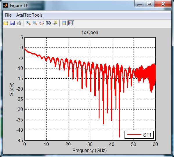
12 OPEN Example 1: Results SHORT USING A FLUSH SHORT (ZERO DELAY) Reasonable correlation with the full 2-port measurement. 12


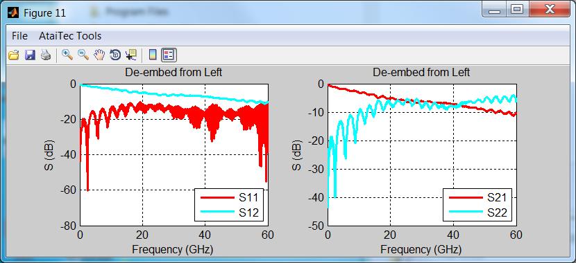
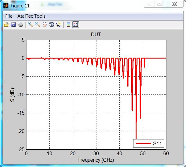
13 Example 1: Results USING OPEN/SHORT MEASURED DATA Methodology provides an estimation of all S-parameters. The S22 is the hardest to estimate accurately with this methodology. 13


14 Example 2: A 32.8 Gbps ATE Test Fixture 1.2 inch 10 mil wide stripline in Meteorwave 2000 ATE INTERFACE 2.4 mm COAXIAL CONNECTOR This is an example for a 32.8 Gbps ATE test fixture. The ATE to test fixture interface is much smaller making a hand probe approach very hard. So a bench setup was developed. In this ATE test fixture PCB example, the DUT side is substituted by a 2.4 mm connector. This allows again an easy comparison between a full 2-port measurement and a 1xreflect based extrapolation of the insertion loss. Reference: [4] 14


15 Example 2: 1x-Reflect Measurement Setup A hand based probing solution like on the pogo pin example is not possible. To address this challenge a bench setup was developed that mimics exactly the ATE interface for this application with a 1.85 mm coaxial connector on the other side. 15
16 Example 2: Results Good correlation with the full 2-port measurement. 16


17 Example 3: A Lossy Test Fixture + Coaxial Cable 50 cm coaxial cable 25 cm 9 mil wide stripline in Nelco SI 50 cm coaxial cable SMA CONNECTOR ATE INTERFACE ATE INTERFACE SMA CONNECTOR 17


18 Example 4: Differential Coupled BGA Test Fixture BECAUSE OF MICROSTRIP TRACE CREATING A GOOD SHORT IS NOT EASY OPEN MEASUREMENT SHORT MEASUREMENT SHORT DEVICE CONDUCTIVE METAL BLOCK PARICON INTERPOSER 18

19 Example 4: Results OPEN MEASURED WITH PROBE IN THE AIR Coupled differential traces creates a tougher challenge (e.g. mode conversion) for the 1x-reflect S-parameter estimation. Creating an open and short on a BGA via field is much harder than on a coaxial connector with a flush short. For verification a 2-port measurement with a differential (GSSG) micro-coaxial probe was performed Coaxial probe also has a loss that was estimated and de-embedded using 1x-reflect. The results show a good correlation at low frequencies that gets worse at higher frequencies because the short and open are also worse at higher frequencies. 19


20 Example 5: A High-End GPU Test Fixture MOTHERBOARD INTERPOSER DAUGHTER CARD ATE SOCKET DAUGHTER CARD INTERPOSER MOTHERBOARD This is a real ATE test fixture example. The test fixture is composed by a motherboard and a daughter card. Signal traces are differential but non-coupled The objective is to estimate the loss of the daughter card. Reference: [5] 20


.")
21 Example 5: A High-End GPU Test Fixture ATE INTERFACE BENCH MEASUREMENT SETUP MOTHERBOARD INTERFACE (BOTTOM SIDE) First measurement is of the motherboard alone (this includes also the 10 inch ATE interconnect cable assembly which is not de-embedded). Second measurement is of the motherboard plus the daughter card. 21
22 Example 5: A High-End GPU Test Fixture WE ARE INTERESTED IN THE LOSS OF THE DAUGHTER CARD The results provide an estimation of the daughter card loss. For the application critical frequency of 12.5 GHz (25 Gbps) the daughter card adds ~1.6 db of insertion loss. 22
23 Conclusions The ATE test fixture is the major performance bottleneck for high-speed digital and high-frequency RF applications. Return loss measurement can be used to estimate the ATE test fixture insertion loss by using an appropriate software tool. Do not use the 1x-reflect blindly. There are always limitations to every algorithm. Open and short quality are critical for the 1x-reflect estimation accuracy. This technique requires a VNA measurement. TDR instruments can provide S11 results through SW post-processing but the accuracy is much lower compared to a VNA measurement. For a thorough comparison of the S-parameter estimation accuracy it is necessary to also take into account the phase when looking at the estimation error. For high accuracy a full 2-port measurement is still the golden standard. The IEEE P370 standard is being developed to provide guidelines for deembedding algorithms accuracy including 1x-reflect based de-embedding. 23
24 References [1] Jose Moreira and Hubert Werkmann, An Engineers Guide to Automated Testing of High- Speed Interfaces, 2 nd Edition, Artech House [2] Ching-Chao Huang, In-Situ De-Embedding, EDI CON, Beijing China [3] Jose Moreira, Heidi Barnes, Callum McCowan and Rose Winters, Time Domain Reflectometry Kit for ATE Test Fixtures, Verigy VOICE Users Conference [4] Jose Moreira, Hubert Werkmann, Daniel Lam and Bernhard Roth, Implementation Challenges of an ATE Test Cell for At-Speed Production Testing of 32 Gbps Applications, BITS China Workshop [5] Jinlei Liu, Derek Lee, Jinglan Jia and Takatoshi Yoshino, V G High Speed Extension Solution to Test High-End GPU, Advantest VOICE Users Conference
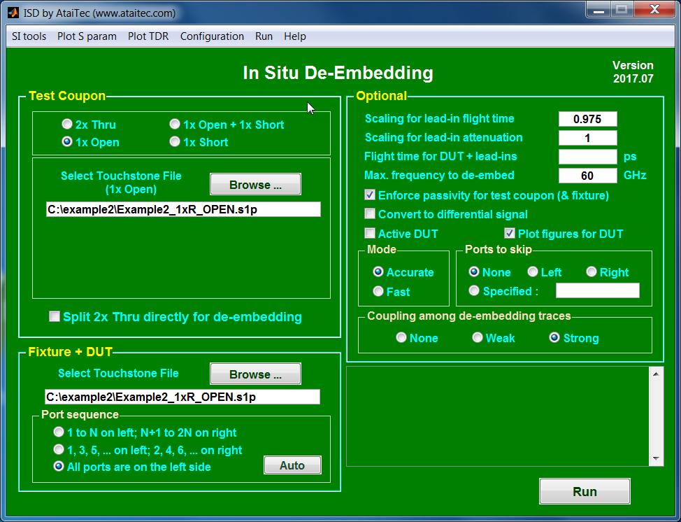
25 ISD Estimation Setup 25
March 15-18, 2015 Hilton Phoenix / Mesa Hotel Mesa, Arizona Archive Session 6
 Proceedings March 15-18, 2015 Hilton Phoenix / Mesa Hotel Mesa, Arizona Archive Session 6 2015 BiTS Workshop Image: BCFC/iStock Session 6 Marc Mössinger Session Chair BiTS Workshop 2015 Schedule Performance
User s Guide Rev 1.0
 User s Guide Rev 1.0 Plug and Play Kit for De-Embedding Software Algorithms Verification Evaluate the Accuracy of De-Embedding Algorithms Purchase Kits Direct from DVT Solutions, LLC Brian Shumaker sales@gigaprobes.com
A Proof of Concept - Challenges of testing high-speed interface on wafer at lower cost
 A Proof of Concept - Challenges of testing high-speed interface on wafer at lower cost How to expand the bandwidth of the cantilever probe card Sony LSI Design Inc. Introduction Design & Simulation PCB
Performance at the DUT: Techniques for Evaluating the Performance of an ATE System at the Device Under Test Socket
 DesignCon 2008 Performance at the DUT: Techniques for Evaluating the Performance of an ATE System at the Device Under Test Socket Heidi Barnes, Verigy, heidi.barnes@verigy.com Jose Moreira, Verigy, jose.moreira@verigy.com
PCB Probing for Signal-Integrity Measurements
 TITLE PCB Probing for Signal-Integrity Measurements Richard Zai, PacketMicro Image PCB Probing for Signal-Integrity Measurements Richard Zai, PacketMicro Richard Zai, Ph.D. CTO, PacketMicro rzai@packetmicro.com
SI Analysis & Measurement as easy as mobile apps ISD, ADK, X2D2
 SI Analysis & Measurement as easy as mobile apps ISD, ADK, X2D2 Ching-Chao Huang huang@ataitec.com Outline Can SI tools be made like mobile apps? Introduction of AtaiTec SI software Most applications in
DesignCon Tips and Advanced Techniques for Characterizing a 28 Gb/s Transceiver
 DesignCon 2013 Tips and Advanced Techniques for Characterizing a 28 Gb/s Transceiver Jack Carrel, Robert Sleigh, Agilent Technologies Heidi Barnes, Agilent Technologies Hoss Hakimi, Mike Resso, Agilent
30 GHz Attenuator Performance and De-Embedment
 30GHz De-Embedment Application Note - Page 1 of 6 Theory of De-Embedment. Due to the need for smaller packages and higher signal integrity a vast majority of todays RF and Microwave components are utilizing
Practical De-embedding for Gigabit fixture. Ben Chia Senior Signal Integrity Consultant 5/17/2011
 Practical De-embedding for Gigabit fixture Ben Chia Senior Signal Integrity Consultant 5/17/2011 Topics Why De-Embedding/Embedding? De-embedding in Time Domain De-embedding in Frequency Domain De-embedding
GT Dual-Row Nano Vertical Thru-Hole High Speed Characterization Report For Differential Data Applications
 GT-16-97 Dual-Row Nano Vertical Thru-Hole For Differential Data Applications 891-007-15S Vertical Thru-Hole PCB 891-001-15P Cable Mount Revision History Rev Date Approved Description A 8/31/2016 R. Ghiselli/G.
De-embedding Gigaprobes Using Time Domain Gating with the LeCroy SPARQ
 De-embedding Gigaprobes Using Time Domain Gating with the LeCroy SPARQ Dr. Alan Blankman, Product Manager Summary Differential S-parameters can be measured using the Gigaprobe DVT30-1mm differential TDR
S-Parameter Measurement and Fixture De-Embedding Variation Across Multiple Teams, Equipment and De- Embedding Tools
 DesignCon 2019 S-Parameter Measurement and Fixture De-Embedding Variation Across Multiple Teams, Equipment and De- Embedding Tools Heidi Barnes, Keysight Technologies, heidi.barnes@keysight.com Eric Bogatin,
RF Characterization Report
 BNC7T-J-P-xx-ST-EMI BNC7T-J-P-xx-RD-BH1 BNC7T-J-P-xx-ST-TH1 BNC7T-J-P-xx-ST-TH2D BNC7T-J-P-xx-RA-BH2D Mated with: RF179-79SP1-74BJ1-0300 Description: 75 Ohm BNC Board Mount Jacks Samtec, Inc. 2005 All
GT Dual-Row Nano Vertical SMT High Speed Characterization Report For Differential Data Applications
 GT-16-95 Dual-Row Nano Vertical SMT For Differential Data Applications 891-011-15S Vertical SMT PCB 891-001-15P Cable Mount Revision History Rev Date Approved Description A 6/3/2016 R. Ghiselli/D. Armani
Monoblock RF Filter Testing SMA, In-Fixture Calibration and the UDCK
 Application Note AN1008 Introduction Monoblock RF Filter Testing SMA, In-Fixture Calibration and the UDCK Factory testing needs to be accurate and quick. While the most accurate (and universally available)
Forensic Analysis of Closed Eyes
 Forensic Analysis of Closed Eyes Dr. Eric Bogatin, Dean, Teledyne LeCroy Signal Integrity Academy Stephen Mueller, Applications Engineering Manager, Teledyne LeCroy Karthik Radhakrishna, Applications Engineer,
Keysight Technologies
 Keysight Technologies A Simple, Powerful Method to Characterize Differential Interconnects Application Note Abstract The Automatic Fixture Removal (AFR) process is a new technique to extract accurate,
SCSI Cable Characterization Methodology and Systems from GigaTest Labs
 lide - 1 CI Cable Characterization Methodology and ystems from GigaTest Labs 134. Wolfe Rd unnyvale, CA 94086 408-524-2700 www.gigatest.com lide - 2 Overview Methodology summary Fixturing Instrumentation
RF Characterization Report
 CJT Series Circular RF Twinax Jack CJT-T-P-HH-ST-TH1 CJT-T-P-HH-RA-BH1 Mated With C28S-XX.XX-SPS8-SPS8 Description: Fully Mated Circular RF Shielded Twisted Pair Twinax Cable Assembly Samtec Inc. WWW.SAMTEC.COM
Application Note AN39
 AN39 9380 Carroll Park Drive San Diego, CA 92121, USA Tel: 858-731-9400 Fax: 858-731-9499 www.psemi.com Vector De-embedding of the PE42542 and PE42543 SP4T RF Switches Introduction Obtaining accurate measurement
Designing High Performance Interposers with 3-port and 6-port S-parameters
 DesignCon 2015 Designing High Performance Interposers with 3-port and 6-port S-parameters Joseph Socha, Nexus Technology joe.socha@nexustechnology.com Jonathan Dandy, Tektronix jonathan.s.dandy@tektronix.com
A Simple, Yet Powerful Method to Characterize Differential Interconnects
 A Simple, Yet Powerful Method to Characterize Differential Interconnects Overview Measurements in perspective The automatic fixture removal (AFR) technique for symmetric fixtures Automatic Fixture Removal
Why Engineers Ignore Cable Loss
 Why Engineers Ignore Cable Loss By Brig Asay, Agilent Technologies Companies spend large amounts of money on test and measurement equipment. One of the largest purchases for high speed designers is a real
Microwave Interconnect Testing For 12G-SDI Applications
 DesignCon 2016 Microwave Interconnect Testing For 12G-SDI Applications Jim Nadolny, Samtec jim.nadolny@samtec.com Corey Kimble, Craig Rapp Samtec OJ Danzy, Mike Resso Keysight Boris Nevelev Imagine Communications
Keysight Technologies De-Embedding and Embedding S-Parameter Networks Using a Vector Network Analyzer. Application Note
 Keysight Technologies De-Embedding and Embedding S-Parameter Networks Using a Vector Network Analyzer Application Note L C Introduction Traditionally RF and microwave components have been designed in packages
Basic Verification of Power Loadpull Systems
 MAURY MICROWAVE 1 Oct 2004 C O R P O R A T I O N Basic Verification of Power Loadpull Systems Author: John Sevic, MSEE Automated Tuner System Technical Manager, Maury Microwave Corporation What is Loadpull
Verification of HBM through Direct Probing on MicroBumps
 Verification of HBM through Direct Probing on MicroBumps FormFactor Sung Wook Moon SK hynix Outline HBM market HBM test flow Device structure overview Key test challenges addressed Signal delivery and
Agilent Validating Transceiver FPGAs Using Advanced Calibration Techniques. White Paper
 Agilent Validating Transceiver FPGAs Using Advanced Calibration Techniques White Paper Contents Overview...2 Introduction...3 FPGA Applications Overview...4 Typical FPGA architecture...4 FPGA applications...5
Intel PCB Transmission Line Loss Characterization Metrology
 Report to IPC D24D: Intel PCB Transmission Line Loss Characterization Metrology Xiaoning Ye, Key Contributors: Jimmy Hsu, Kai Xiao, et al. 1 Background Current IPC test methods under TM-650 are not adequate
RF Characterization Report
 HDBNC Series RF Connector HDBNC-J-P-GN-ST-EM1 HDBNC-J-P-GN-ST-BH1 HDBNC-J-P-GN-ST-TH1 Description: 75 Ohm True 75 TM High Density BNC Straight Jack, Edge Mount or Through-hole Samtec Inc. WWW.SAMTEC.COM
Senior Project Manager / AEO
 Kenny Liao 2018.12.18&20 Senior Project Manager / AEO Measurement Demo Prepare instrument for measurement Calibration Fixture removal Conclusion What next? Future trends Resources Acquire channel data
Microwave Interconnect Testing For 12G SDI Applications
 TITLE Microwave Interconnect Testing For 12G SDI Applications Jim Nadolny, Samtec Image Corey Kimble, Craig Rapp - Samtec OJ Danzy, Mike Resso - Keysight Boris Nevelev - Imagine Communications Microwave
ENGINEERING COMMITTEE
 ENGINEERING COMMITTEE Interface Practices Subcommittee AMERICAN NATIONAL STANDARD ANSI/SCTE 04 2014 Test Method for F Connector Return Loss NOTICE The Society of Cable Telecommunications Engineers (SCTE)
Saving time & money with JTAG
 Saving time & money with JTAG AltiumLive 2017: ANNUAL PCB DESIGN SUMMIT Simon Payne CEO, XJTAG Ltd. Saving time and money with JTAG JTAG / IEEE 1149.X Take-away points Get JTAG right from the start Use
ENGINEERING COMMITTEE Interface Practices Subcommittee AMERICAN NATIONAL STANDARD ANSI/SCTE
 ENGINEERING COMMITTEE Interface Practices Subcommittee AMERICAN NATIONAL STANDARD ANSI/SCTE 48-3 2011 Test Procedure for Measuring Shielding Effectiveness of Braided Coaxial Drop Cable Using the GTEM Cell
Electrical Sampling Modules Datasheet 80E11 80E11X1 80E10B 80E09B 80E08B 80E07B 80E04 80E03 80E03-NV
 Electrical Sampling Modules Datasheet 80E11 80E11X1 80E10B 80E09B 80E08B 80E07B 80E04 80E03 80E03-NV The DSA8300 Series Sampling Oscilloscope, when configured with one or more electrical sampling modules,
#P46. Time Domain Reflectometry. Q: What is TDR and how does it work?
 #P46 Time Domain Reflectometry is a technique used to determine the signal s distance from source to load. The delay found inherent in the environment can be compensated for through automatic calibration,
Keysight Method of Implementation (MOI) for VESA DisplayPort (DP) Standard Version 1.3 Cable-Connector Compliance Tests Using E5071C ENA Option TDR
 for VESA DisplayPort (DP) Standard Version 1.3 Cable-Connector Compliance Tests Using E5071C ENA Option TDR") Revision 1.00 February 27, 2015 Keysight Method of Implementation (MOI) for VESA DisplayPort (DP) Standard Version 1.3 Cable-Connector Compliance Tests Using E5071C ENA Option TDR 1 Table of Contents 1.
Revision 1.00 February 27, 2015 Keysight Method of Implementation (MOI) for VESA DisplayPort (DP) Standard Version 1.3 Cable-Connector Compliance Tests Using E5071C ENA Option TDR 1 Table of Contents 1.
MM-wave Partial Information De-embedding: Errors and Sensitivities. J. Martens
 MM-wave Partial Information De-embedding: Errors and Sensitivities J. Martens MM-wave Partial Information De-embedding: Errors and Sensitivities J. Martens Anritsu Company, Morgan Hill CA US Abstract De-embedding
ELECTRICAL PERFORMANCE REPORT
 CIRCUITS & DESIGN ELECTRICAL PERFORMANCE REPORT DENSIPAC 4 ROW Date: 06-12-2006 Circuits & Design EMEA Circuits & Design 1/21 06/12/2006 1 INTRODUCTION... 3 2 CONNECTORS, TEST BOARDS AND TEST EQUIPMENT...
Tutorial Session 8:00 am Feb. 2, Robert Schaefer, Agilent Technologies Feb. 2, 2009
 Tutorial Session 8:00 am Feb. 2, 2009 Robert Schaefer, Agilent Technologies Feb. 2, 2009 Objectives Present Advanced Calibration Techniques Summarize Existing Techniques Present New Advanced Calibration
Transcom Instruments. Product Brochure TRANSCOM INSTRUMENTS. Product Brochure. 1
 TRANSCOM INSTRUMENTS Product Brochure Transcom Instruments Product Brochure www.transcomwireless.com 1 T5000 Series Bench-top Vector Network Analyzer Overview T5000 Series Bench-top Vector Network Analyzer
R&S ZN-Z32/-Z33 Automatic In-line Calibration Modules Ensuring high accuracy with thermal vacuum testing and multiport measurements
 R&S ZN-Z32/-Z33 Automatic In-line Calibration Modules Ensuring high accuracy with thermal vacuum testing and multiport measurements Product Brochure Version 01.01 R&S ZN-Z32/-Z33 Automatic In-Line Calibration
Using Allegro PCB SI GXL to Make Your Multi-GHz Serial Link Work Right Out of the Box
 Using Allegro PCB SI GXL to Make Your Multi-GHz Serial Link Work Right Out of the Box Session 8.11 - Hamid Kharrati - A2e Technologies Agenda About the Project Modeling the System Frequency Domain Analysis
SignalCorrect Software and TCS70902 Calibration Source Option SC SignalCorrect software
 SignalCorrect Software and TCS70902 Calibration Source Option SC SignalCorrect software Eye of signal after de-embed using SignalCorrect Features and benefits Measurement and de-embed: Characterize cables
Multi-GB/s Serial Channel Design Using a Hybrid Measurement and Simulation Platform
 DesignCon 2008 Multi-GB/s Serial Channel Design Using a Hybrid Measurement and Simulation Platform Andrew Byers, Ansoft Corporation abyers@ansoft.com Dima Smolyansky, Tektronix dmitry.a.smolyansky@tektronix.com
Limitations of a Load Pull System
 Limitations of a Load Pull System General Rule: The Critical Sections in a Load Pull measurement setup are the sections between the RF Probe of the tuners and the DUT. The Reflection and Insertion Loss
Electrical Sampling Modules
 Electrical Sampling Modules 80E11 80E11X1 80E10B 80E09B 80E08B 80E07B 80E04 80E03 80E03-NV Datasheet Applications Impedance Characterization and S-parameter Measurements for Serial Data Applications Advanced
Vector Network Analyzer TTR503A/TTR506A USB Vector Network Analyzer Preliminary Datasheet. Subject to change.
 Vector Network Analyzer TTR503A/TTR506A USB Vector Network Analyzer Preliminary Datasheet. Subject to change. Applications Academic/Education Design, development and manufacturing of passive and active
INTRODUCTION This procedure should only be performed if the instrument fails to meet the Performance Check tests for Output Zero or Offset Accuracy
 INTRODUCTION This procedure should only be performed if the instrument fails to meet the Performance Check tests for Output Zero or Offset Accuracy (steps A and B). Gain, which affects DC Accuracy, cannot
Optimizing BNC PCB Footprint Designs for Digital Video Equipment
 Optimizing BNC PCB Footprint Designs for Digital Video Equipment By Tsun-kit Chin Applications Engineer, Member of Technical Staff National Semiconductor Corp. Introduction An increasing number of video
Agilent 87075C 75 Ohm Multiport Test Sets for use with Agilent E5061A ENA-L Network Analyzers
 Agilent 87075C 75 Ohm Multiport Test Sets for use with Agilent E5061A ENA-L Network Analyzers Technical Overview Focus on testing, not reconnecting! Maximize production throughput of cable-tv multiport
R&S RT-ZM Modular Probe System
 RT-ZMxx_fly_3607-5690-32_v0102.indd 3 roduct Flyer 01.02 3607.5690.32 01.02 D 1 en Test & Measurement R&S RT-ZM Modular robe System 08.11.2016 16:20:21 Addressing high-speed probing challenges Serv The
Agilent MOI for HDMI 1.4b Cable Assembly Test Revision Jul 2012
 Revision 1.11 19-Jul 2012 Agilent Method of Implementation (MOI) for HDMI 1.4b Cable Assembly Test Using Agilent E5071C ENA Network Analyzer Option TDR 1 Table of Contents 1. Modification Record... 4 2.
ENGINEERING COMMITTEE Interface Practices Subcommittee AMERICAN NATIONAL STANDARD ANSI/SCTE Mainline Pin (plug) Connector Return Loss
 Connector Return Loss") ENGINEERING COMMITTEE Interface Practices Subcommittee AMERICAN NATIONAL STANDARD ANSI/SCTE 125 2007 Mainline Pin (plug) Connector Return Loss NOTICE The Society of Cable Telecommunications Engineers (SCTE)
ENGINEERING COMMITTEE Interface Practices Subcommittee AMERICAN NATIONAL STANDARD ANSI/SCTE 125 2007 Mainline Pin (plug) Connector Return Loss NOTICE The Society of Cable Telecommunications Engineers (SCTE)
EMI/EMC diagnostic and debugging
 EMI/EMC diagnostic and debugging 1 Introduction to EMI The impact of Electromagnetism Even on a simple PCB circuit, Magnetic & Electric Field are generated as long as current passes through the conducting
Measurement Accuracy of the ZVK Vector Network Analyzer
 Product: ZVK Measurement Accuracy of the ZVK Vector Network Analyzer Measurement deviations due to systematic errors of a network analysis system can be drastically reduced by an appropriate system error
PI3PCIE2612-A. High Bandwidth, 6-Differential Channel 1:2 DP/PCIe Gen2 Display Mux, ATX Pinout. Features. Description
 Features 6 Differential Channel, 1 to 2 demux that will support 5.0Gbps PCIexpress Gen2 signals on one path, and DP 1.1 signals on the second path Insertion Loss for high speed channels @ 5.0 Gbps: -5.0dB
MPI Cable Selection Guide
 MPI Cable Selection Guide MPI engineers focus to provide on optimal cable solutions taking into account a number of requirements specific for wafer-level measurement systems: optimal cable length, cable
Switching Solutions for Multi-Channel High Speed Serial Port Testing
 Switching Solutions for Multi-Channel High Speed Serial Port Testing Application Note by Robert Waldeck VP Business Development, ASCOR Switching The instruments used in High Speed Serial Port testing are
Keysight Technologies M8048A ISI Channels
 Keysight Technologies M8048A ISI Channels Master Your Next Designs Data Sheet Key features Emulate a wide range of channel loss with cascadable ISI traces with fine resolution 4 short (7.7 to 12.8 ) and
New Serial Link Simulation Process, 6 Gbps SAS Case Study
 ew Serial Link Simulation Process, 6 Gbps SAS Case Study Donald Telian SI Consultant Session 7-TH2 Donald Telian SI Consultant About the Authors Donald Telian is an independent Signal Integrity Consultant.
Combating Closed Eyes Design & Measurement of Pre-Emphasis and Equalization for Lossy Channels
 Combating Closed Eyes Design & Measurement of Pre-Emphasis and Equalization for Lossy Channels Why Test the Receiver? Serial Data communications standards have always specified both the transmitter and
Combating Closed Eyes Design & Measurement of Pre-Emphasis and Equalization for Lossy Channels
 Combating Closed Eyes Design & Measurement of Pre-Emphasis and Equalization for Lossy Channels Why Test the Receiver? Serial Data communications standards have always specified both the transmitter and
Agilent 8510XF Vector Network Analyzer Single-Connection, Single-Sweep Systems Product Overview
 Agilent 8510XF Vector Network Analyzer Single-Connection, Single-Sweep Systems Product Overview Discontinued Product Information For Support Reference Only Information herein, may refer to products/services
Sharif University of Technology. SoC: Introduction
 SoC Design Lecture 1: Introduction Shaahin Hessabi Department of Computer Engineering System-on-Chip System: a set of related parts that act as a whole to achieve a given goal. A system is a set of interacting
De-embedding Techniques For Passive Components Implemented on a 0.25 µm Digital CMOS Process
 PIERS ONLINE, VOL. 3, NO. 2, 27 184 De-embedding Techniques For Passive Components Implemented on a.25 µm Digital CMOS Process Marc D. Rosales, Honee Lyn Tan, Louis P. Alarcon, and Delfin Jay Sabido IX
PCI Express. Francis Liu Project Manager Agilent Technologies. Nov 2012
 PCI Express Francis Liu Project Manager Agilent Technologies Nov 2012 PCI Express 3.0 Agilent Total Solution Physical layer interconnect design Physical layertransmitter test Physical layerreceiver test
SUHNER QMA SUBMINIATURE CONNECTORS
 SUHNER QMA SUBMINIATURE CONNECTORS Description Content Page SUHNER QMA coaxial connectors are available with 50 Ω impedance. The frequency range extends to 11 GHz, depending on the connector and cable
Agilent 87075C Multiport Test Set Product Overview
 Agilent 87075C Multiport Test Set Product Overview A complete 75 ohm system for cable TV device manufacturers Now, focus on testing, not reconnecting! For use with the Agilent 8711 C-Series of network
In-situ Port Cal for Dual Carriages Tuner
 In-situ Port Cal for Dual Carriages Tuner In-Situ port cal method is the calibration technique mainly for cascaded tuners or multi-carriage tuner. Unlike in-situ system cal which requires 2 VNA calibrations
ENGINEERING COMMITTEE Interface Practices Subcommittee AMERICAN NATIONAL STANDARD ANSI/SCTE
 ENGINEERING COMMITTEE Interface Practices Subcommittee AMERICAN NATIONAL STANDARD ANSI/SCTE 102 2010 Cable Retention Force Testing of Trunk & Distribution Connectors NOTICE The Society of Cable Telecommunications
RF (Wireless) Fundamentals 1- Day Seminar
 Fundamentals 1- Day Seminar") RF (Wireless) Fundamentals 1- Day Seminar In addition to testing Digital, Mixed Signal, and Memory circuitry many Test and Product Engineers are now faced with additional challenges: RF, Microwave and
RF (Wireless) Fundamentals 1- Day Seminar In addition to testing Digital, Mixed Signal, and Memory circuitry many Test and Product Engineers are now faced with additional challenges: RF, Microwave and
16 Dec Testing and Programming PCBA s. 1 JTAG Technologies
 6 Dec 24 Testing and Programming PCBA s JTAG Technologies The importance of Testing Don t ship bad products to your customers, find problems before they do. DOA s (Death On Arrival) lead to huge costs
Sidelighter TM Optical distance to fault measurement module
 Sidelighter TM Optical distance to fault measurement module Available only at: Sidelighter TM Introducing the latest in optical fiber measurements and versatility Artisan Laboratories Corporation s hand
Analyzing Modulated Signals with the V93000 Signal Analyzer Tool. Joe Kelly, Verigy, Inc.
 Analyzing Modulated Signals with the V93000 Signal Analyzer Tool Joe Kelly, Verigy, Inc. Abstract The Signal Analyzer Tool contained within the SmarTest software on the V93000 is a versatile graphical
ENGINEERING COMMITTEE
 ENGINEERING COMMITTEE Interface Practices Subcommittee SCTE STANDARD SCTE 45 2017 Test Method for Group Delay NOTICE The Society of Cable Telecommunications Engineers (SCTE) Standards and Operational Practices
RF amplifier testing from wafer to design-in
 RF amplifier testing from wafer to design-in We help you reach your target: Improve efficiency Ensure RF performance Increase throughput Turn your signals into success. Benefit from 85 years of experience
Transcom Instruments. Product Brochure TRANSCOM INSTRUMENTS. Product Brochure
 TRANSCOM INSTRUMENTS Product Brochure Transcom Instruments Product Brochure TRANSCOM T5000 Series Bench-top Vector Network Analyzer Overview T5000 Series bench-top vector network analyzer offers the high
Ilmenau, 9 Dec 2016 Testing and programming PCBA s. 1 JTAG Technologies
 Ilmenau, 9 Dec 206 Testing and programming PCBA s JTAG Technologies The importance of Testing Don t ship bad products to your customers, find problems before they do. DOA s (Death On Arrival) lead to huge
Simulations of Duobinary and NRZ Over Selected IEEE Channels (Including Jitter and Crosstalk)
") Simulations of Duobinary and NRZ Over Selected IEEE Channels (Including Jitter and Crosstalk) IEEE 82.3ap Meeting Vancouver January, 25 Stephen D. Anderson Xilinx, Inc. stevea@xilinx.com Purpose Channels
Simulations of Duobinary and NRZ Over Selected IEEE Channels (Including Jitter and Crosstalk) IEEE 82.3ap Meeting Vancouver January, 25 Stephen D. Anderson Xilinx, Inc. stevea@xilinx.com Purpose Channels
LA GHz Vector Network Analyser
 LA19-13-02 DW96659 iss. 1.8 1 of (74) LA19-13-02 3 GHz Vector Network Analyser User s Manual LA Techniques Ltd The Works, Station Road Tel: 01372 466040 Claygate, Surrey KT10 9DH Fax: 01372 466688 VAT
MILLIMETER WAVE VNA MODULE BROCHURE
 MILLIMETER WAVE VNA MODULE BROCHURE General Information OML, founded in 1991, is an expert at millimeter wave (mm-wave) measurements. Our successful foundation is built on mm-wave S-parameter measurements,
18 Nov 2015 Testing and Programming PCBA s. 1 JTAG Technologies
 8 Nov 25 Testing and Programming PCBA s JTAG Technologies The importance of Testing Don t ship bad products to your customers, find problems before they do. DOA s (Death On Arrival) lead to huge costs
LadyBug Technologies, LLC LB5908A True-RMS Power Sensor
 LadyBug Technologies, LLC LB5908A True-RMS Power Sensor LB5908ARev8 LadyBug Technologies www.ladybug-tech.com Telephone: 707-546-1050 Page 1 LB5908A Data Sheet Key PowerSensor+ TM Specifications Frequency
Avoiding False Pass or False Fail
 Avoiding False Pass or False Fail By Michael Smith, Teradyne, October 2012 There is an expectation from consumers that today s electronic products will just work and that electronic manufacturers have
Brian Holden Kandou Bus, S.A. IEEE GE Study Group September 2, 2013 York, United Kingdom
 Simulation results for NRZ, ENRZ & PAM-4 on 16-wire full-sized 400GE backplanes Brian Holden Kandou Bus, S.A. brian@kandou.com IEEE 802.3 400GE Study Group September 2, 2013 York, United Kingdom IP Disclosure
The high-end network analyzers from Rohde & Schwarz now include an option for pulse profile measurements plus, the new R&S ZVA 40 covers the
 GENERAL PURPOSE 44 448 The high-end network analyzers from Rohde & Schwarz now include an option for pulse profile measurements plus, the new R&S ZVA 4 covers the frequency range up to 4 GHz. News from
Spring Probes and Probe Cards for Wafer-Level Test. Jim Brandes Multitest. A Comparison of Probe Solutions for an RF WLCSP Product
 Session 6 AND, AT THE WAFER LEVEL For many in the industry, performing final test at the wafer level is still a novel idea. While providing some much needed solutions, it also comes with its own set of
How to overcome/avoid High Frequency Effects on Debug Interfaces Trace Port Design Guidelines
 How to overcome/avoid High Frequency Effects on Debug Interfaces Trace Port Design Guidelines An On-Chip Debugger/Analyzer (OCD) like isystem s ic5000 (Figure 1) acts as a link to the target hardware by
7 Nov 2017 Testing and programming PCBA s
 7 Nov 207 Testing and programming PCBA s Rob Staals JTAG Technologies Email: robstaals@jtag.com JTAG Technologies The importance of Testing Don t ship bad products to your customers, find problems before
A Briefing on IEEE Standard Test Access Port And Boundary-Scan Architecture ( AKA JTAG )
") A Briefing on IEEE 1149.1 1990 Standard Test Access Port And Boundary-Scan Architecture ( AKA JTAG ) Summary With the advent of large Ball Grid Array (BGA) and fine pitch SMD semiconductor devices the
A Briefing on IEEE 1149.1 1990 Standard Test Access Port And Boundary-Scan Architecture ( AKA JTAG ) Summary With the advent of large Ball Grid Array (BGA) and fine pitch SMD semiconductor devices the
Investigation of Deembedding. up to 110GHz J.BAZZI *1, C. RAYA, A.CURUTCHET *, F.POURCHON #, N.DERRIER #, D.CELI #, T.ZIMMER *
 Investigation of Deembedding procedures up to 110GHz J.BAZZI *1, C. RAYA, A.CURUTCHET *, F.POURCHON #, N.DERRIER #, D.CELI #, T.ZIMMER * 1 jad.bazzi@ims-bordeaux.fr * IMS Laboratory # STMicroelectronics
HMC958LC5 HIGH SPEED LOGIC - SMT. Typical Applications. Features. Functional Diagram. General Description
 Typical Applications Features The HMC958LC5 is ideal for: SONET OC-192 and 1 GbE 16G Fiber Channel 4:1 Multiplexer Built-In Test Broadband Test & Measurement Functional Diagram Supports High Data Rates:
Measurements and Simulation Results in Support of IEEE 802.3bj Objective
 Measurements and Simulation Results in Support of IEEE 802.3bj Objective Jitendra Mohan, National Semiconductor Corporation Pravin Patel, IBM Zhiping Yang, Cisco Peerouz Amleshi, Mark Bugg, Molex Sep 2011,
SI Design & Measurement Principles and Best Practices
 I ment Principles and Best Practices 13 May, 2015 Heidi Barnes enior Application Engineer High peed Digital Design Keysight EEof EDA Division In collaboration with: Ben Chia enior ignal Integrity Consultant
Keysight N1055A Remote Head Module 35/50 GHz 2/4 Port TDR/TDT
 Keysight N1055A Remote Head Module 35/50 GHz 2/4 Port TDR/TDT For the 86100D DCA-X Series Oscilloscope Mainframe Data Sheet Engineered for easy, accurate impedance and S-parameter measurements on multi-port
Emphasis, Equalization & Embedding
 Emphasis, Equalization & Embedding Cleaning the Rusty Channel Gustaaf Sutorius Application Engineer Agilent Technologies gustaaf_sutorius@agilent.com Dr. Thomas Kirchner Senior Application Engineer Digital
Keysight Technologies Method of Implementation (MOI) for BroadR-Reach Link Segment Tests Using E5071C ENA Option TDR
 for BroadR-Reach Link Segment Tests Using E5071C ENA Option TDR") Revision 2.00 August 28, 2014 BroadR-Reach Link Segment Keysight Technologies Method of Implementation (MOI) for BroadR-Reach Link Segment Tests Using E5071C ENA Option TDR 1 Table of Contents 1. Revision
Revision 2.00 August 28, 2014 BroadR-Reach Link Segment Keysight Technologies Method of Implementation (MOI) for BroadR-Reach Link Segment Tests Using E5071C ENA Option TDR 1 Table of Contents 1. Revision
Cable Retention Force Testing of Trunk & Distribution Connectors
 ENGINEERING COMMITTEE Interface Practices Subcommittee AMERICAN NATIONAL STANDARD ANSI/SCTE 102 2016 Cable Retention Force Testing of Trunk & Distribution Connectors NOTICE The Society of Cable Telecommunications