WALKING A TIGHT ROPE
|
|
|
- Lora Cunningham
- 6 years ago
- Views:
Transcription
1 MAXIMUM REACH ENTERPRISES 1853 Wellington Court Henderson, NV Ph: cox.net 07 August 2013 WALKING A TIGHT ROPE Last month, I saw a video where Nik Wallenda walked a 2 diameter wire rope 1,400 long that was 1,500 above the stream bed of a gorge near the Grand Canyon. To view the video, put your cursor on the link below, press Ctrl and then click on the link to watch Nik walking the tight rope! I was intrigued, not so much by his walking ability, but by the layout of the cable across the canyon. I felt that this would be a practical application so I decided to use the Guyline Properties Program on my website and see if I could duplicate the configuration of the cable using the information above. I couldn t tell in the video what kind of anchorage was used, but rock bolts and strand jacks would work very well in a remote area. Thinking that it would be easier to walk if there wasn t too much sag in the cable and that it would be better to walk down hill if possible, I decided to limit the sag to about 25 and place the upper support 30 above the lower support. Using 80,000 lbs (36.36 Te) of horizontal tension in the cable provided a sag of In the video, it looked like the cable sloped somewhat from the upper support down to the bottom support. Note in the guyline properties program print outs below that if the support on the starting side of the canyon is 30 higher than the support on the far side of the canyon (the end of walk side), that the cable is almost all downhill with a small climb up at the end of the walk. Piece of cake. INPUT DATA

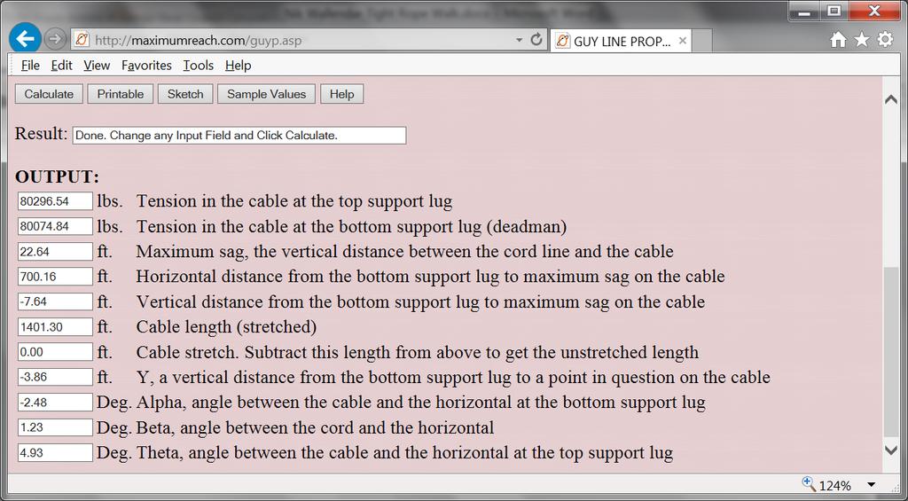
2 OUTPUT DATA
3 By using my program and the input data and using X at 100 increments, I found that for a: X = 100 Y = -3.8 X = 200 Y = -6.8 X = 300 Y = -8.8 X = 400 Y = -9.9 X = 500 Y = 10.1 X = 600 Y = -9.3 X = 700 Y = -7.6 X = 800 Y = -5.1 X = 900 Y = -1.5 X = 950 Y = O.6 X = 1000 Y = 2.9 X = 1100 Y = 8.3 X = 1200 Y = 14.6 X = 1300 Y = 21.9 X = 1400 Y = 30.0 By plotting these values, they show that at the lower support, the cable starts off sloping down at an angle of 2.48 degrees, At about 500 it bottoms out at 10 below the lower support and starts sloping up. At about 950 it crosses the level line from the bottom support. From there it continues to slope up until it is 30 above the lower support, ie, to the level of the top support.
4 I also made a run with the upper support 60 above the lower support. With the horizontal tension still at 80,000 lbs., the sag was about the same but the angle at the bottom was reduced to degrees. So the cable was pretty much downhill all the way from the upper support. The guyline properties program is used to find the properties of a cable hanging under its own weight as a catenary and does not take into account a load placed on it. I used it for the above example as the weight of a 200 lb. walker would not increase the tension in the cable very much due to the flatness of the cable and high tension required to maintain a 22.6 sag. But a 200 lb. load would increase the tension somewhat. The following steps show how to calculate how much the increase in tension would be by keeping the sag the same as in the printout above. This information came from the United States Steel Handbook, page 46, shown below.

5 Go to the following website to purchase a copy of this handbook: BOOK-1946-/
6
7 Reference the drawing and formulas above where the cable has an inclined span and a single load at the center. The tension in the cable is greatest when the load is at the center. Also, the tension in cable is greatest at the upper support. Notice that in the drawing that the horizontal reference line is taken at the upper support, whereas in my sketch it is taken at the lower support. The horizontal tension T in a cable with a 200 lb. load hanging at the center of the span is: T = S(2*G+w*S)/(8*Yc-4*H) where S = the 1,400 span G = the 200 lb. load w = 7.39 lb./ft of 2 ϕ cable weight Yc = the 37.6 vertical distance from the lower support to the upper support + the vertical distance from the lower support to a point down on the cable at the center of the span which = 30 between supports from the printout above where X = 700. H = the 30 vertical distance between the lower and upper supports = 1,400(2* *1,400)/(8*37.6 4*30) = 83,210 lbs. The angle B1 at the upper support is: Tan (B1) = (G + ws)/2*/t + H/S = ( *1,400)/2*83, /1,400 = B1 = 4.85 This closely matches the 4.93 found in the printout above The tension T1 in cable at the upper support is: T1 = T*Sec(B1) = T/Cos(B1) = 83,509 lbs. So, the increase in tension due to a 200 lb. walker is 83,509 80,296 = 3,213 lbs. The safe working load (SWl) of a 2 ϕ EIPS wire rope is: Breaking strength of a 2 ϕ EIPS wire rope = 396,000 lbs. The safety factor for a stationary wire rope ie, a guyline = 3.0:1 The safety factor for a running wire rope, ie, a hoist line = 3.5:1 So being conservative and using the 3.5:1 S.F. The SWL of the wire rope is 396,000/ ,000 lbs. 113,000 lbs. > 83,509 lbs. === GOOD
8 It is not clear in the video how the cable is tied off or connected to the anchorage, but the worst case for a reduction in SWL for say using cable clamps would be 0.80 and a best case of 1.0 using spelter sockets. 113,000 lbs. * ,000 lbs. ==== STILL GOOD END OF PRESENTATION
MAXIMUM REACH ENTERPRISES 1853 Wellington Court Henderson, NV Ph: cox.net 20 December 2018
 MAXIMUM REACH ENTERPRISES 1853 Wellington Court Henderson, NV 89014 Ph: 702 547 1564 kent.goodman @ cox.net www.maximumreach.com 20 December 2018 BUSINESS CARDS In my early years as a rigging engineer,
OCC Installation Figure 8 Guidelines Excerpt from Optical Cable Corporation s INSTALLATION GUIDE
 Installation Figure 8 Guidelines Excerpt from Optical Corporation s INSTALLATION GUIDE Figure 8 A figure 8 fiber optic cable design incorporates a steel or dielectric messenger into the fiber optic cable
OCC Installation Round Messenger Guidelines Excerpt from Optical Cable Corporation s INSTALLATION GUIDE
 Installation Round Messenger Guidelines Excerpt from Optical Cable Corporation s INSTALLATION GUIDE Round Messenger (ADSS) A round messenger fiber optic cable is designed for use in aerial installations
C A R G O C O N T R O L. By Fritz Dahlin
 C A R G O C O N T R O L By Fritz Dahlin What Our TESTING & RESEARCH Shows Note: Please be aware that this testing was done with new product under controlled conditions. NO product should EVER be used above
WIRE AND CABLE FIRE TESTS
 TEST CSA C22.2 No 2556-13 Section 9.4 (FV-2/VW-1) (Small Scale Vertical) # OF VALUES REPORTED FOOTAGE REQUIRED 3 3 pieces: 24 each 5 7 days PERFORMANCE TIME CSA-FT1 (Small Scale Vertical) 3 5 pieces: 24
UNOLS Wire Pool Database. Presented by Rick Trask Woods Hole Oceanographic Institution
 UNOLS Wire Pool Database Presented by Rick Trask Woods Hole Oceanographic Institution Database Development: A Collaborative Effort Rick Trask, Wire Pool Manager Ruthanne Molyneaux, Administrative Support
PHY221 Lab 1 Discovering Motion: Introduction to Logger Pro and the Motion Detector; Motion with Constant Velocity
 PHY221 Lab 1 Discovering Motion: Introduction to Logger Pro and the Motion Detector; Motion with Constant Velocity Print Your Name Print Your Partners' Names Instructions August 31, 2016 Before lab, read
World s Thinnest Flat Panel Mounting Solutions
 World s Thinnest Flat Panel Mounting Solutions .4" Nobody Gets you closer Introducing Slimline the world s thinnest flat panel mounting solution at only 0.4 inches from the wall, only from Peerless. Designed
Aerial Cable Installation Best Practices
 Aerial Cable Installation Best Practices Panduit Corp. 2007 BEST PRACTICES Table of Contents 1.0 General... 3 2.0 Introduction... 3 3.0 Precautions... 4 4.0 Pre-survey... 5 5.0 Materials and Equipment...
Section 8 FIBERLIGN Hardware for Aerial FTTP Applications
 Section FIBERLIGN Hardware for Aerial FTTP Applications Table of Contents Page FIBERLIGN Products for ADSS Applications FIBERLIGN ADSS Drop Cable Dead-end...-2 FIBERLIGN Midspan Drop...-5 FIBERLIGN LITE
Lashing Rods NOMENCLATURE GENERAL RECOMMENDATIONS. C = D x m = D x.666. m = D x.414. m = D x.483. C = (D + m) x.850. Length.
 x.850. Length.") Lashing s NOMENCLATURE Deburred and : Assist in identification of size, corresponding to tabular information appearing on price pages. diameter: Identifies size of metal wire, corresponding to tabular
Lashing s NOMENCLATURE Deburred and : Assist in identification of size, corresponding to tabular information appearing on price pages. diameter: Identifies size of metal wire, corresponding to tabular
SCHEDA TECNICA. Amarro per cavi 13,5mm Amarro per cavi 16,5mm. MS217F00 Amarro per cavi 13,5mm MS218F00 Amarro per cavi 16,5mm
 SCHEDA TECNICA Amarro per cavi 13,5mm Amarro per cavi 16,5mm Material: Galvanized steel MS217F00 Amarro per cavi 13,5mm MS218F00 Amarro per cavi 16,5mm For cable 13,5mm For cable 16,5mm 3. Weight The weight
SPECIFICATION FIBER OPTIC SPLICE CLOSURE. Spec No : VSS-1007-BS403A-04A/SD. VSS-0107-BS403A-04A/SD R & D Center Manufacturing Division
 SPECIFICATION FIBER OPTIC SPLICE CLOSURE Model Spec. No. Distribution Depts. VSOF-BS403A VSS-0107-BS403A-04A/SD R & D Center Manufacturing Division Sales Division Management Division Revision 10. 07 (Rev.4)
TECHNICAL SPECIFICATION
 TECHNICAL SPECIFICATION (FIBER OPTIC SPLICE CLOSURE) Model Spec. No. Distribution Depts. VSOF-BS403A SJP-0609-403A-01A/SD Quality Assurance Team Manufacturing Division Sales Division Management Division
White Paper. Discone Antenna Design
 White Paper Discone Antenna Design Written by Bill Pretty Highpoint Security Technologies Property of Highpoint Security Technologies Inc The user of this document may use the contents to recreate the
E X P E R I M E N T 1
 E X P E R I M E N T 1 Getting to Know Data Studio Produced by the Physics Staff at Collin College Copyright Collin College Physics Department. All Rights Reserved. University Physics, Exp 1: Getting to
OCC Installation Conduit Guidelines Excerpt from Optical Cable Corporation s INSTALLATION GUIDE
 Installation Conduit Guidelines Excerpt from Optical Cable Corporation s INSTALLATION GUIDE Conduit Installation A conduit cable installation involves placement of one or more optical cables inside a preinstalled
ACADEMIC SUCCESS CENTER THE COLLEGE AT BROCKPORT STATE UNIVERSITY OF NEW YORK PROJECT NO
 SECTION 270536 - CABLE TRAYS FOR COMMUNICATIONS SYSTEMS PART 1 - GENERAL 1.1 RELATED DOCUMENTS A. Drawings and general provisions of the Contract, including General and Supplementary Conditions and Division
All Dielectric Self Supporting (ADSS) Fiber Optic Cable Installation
 Fiber Optic Cable Installation") All Dielectric Self Supporting (ADSS) Fiber Optic Cable Installation Underground Installation M P - 1012 Issue #3 March 2011 DISCLAIMER OF WARRANTIES AND LIMITATION OF LIABILITIES The practices contained
All Dielectric Self Supporting (ADSS) Fiber Optic Cable Installation Underground Installation M P - 1012 Issue #3 March 2011 DISCLAIMER OF WARRANTIES AND LIMITATION OF LIABILITIES The practices contained
Simple and highly effective technology to communicate your brand s distinctive character
 . . . Advantages 4 Simple and highly effective technology to communicate your brand s distinctive character COST EFFECTIVE No need to print graphics, you can change your message every day! No media player
Defining and Labeling Circuits and Electrical Phasing in PLS-CADD
 610 N. Whitney Way, Suite 160 Madison, WI 53705 Phone: 608.238.2171 Fax: 608.238.9241 Email:info@powline.com URL: http://www.powline.com Defining and Labeling Circuits and Electrical Phasing in PLS-CADD
LabView Exercises: Part II
 Physics 3100 Electronics, Fall 2008, Digital Circuits 1 LabView Exercises: Part II The working VIs should be handed in to the TA at the end of the lab. Using LabView for Calculations and Simulations LabView
RIPPLE TANK - projection, with strobe & kit
 RIPPLE TANK - projection, with strobe & kit DESCRIPTION: Cat: SW3440-001 projection type with stroboscope, rippler & kit. The images created by IEC Ripple Tank Projection type are viewed from the side
GS122-2L. About the speakers:
 Dan Leighton DL Consulting Andrea Bell GS122-2L A growing number of utilities are adapting Autodesk Utility Design (AUD) as their primary design tool for electrical utilities. You will learn the basics
Commissioning Lock Issues:
 Commissioning Lock Issues: Reminder I: Scope and goals Reminder II: The design Transforming a virtual world to reality Reality strikes How to adopt reality? Preparations for 3 string cable arm Béla Majorovits
Cambridge International Examinations Cambridge International General Certificate of Secondary Education
 Cambridge International Examinations Cambridge International General Certificate of Secondary Education *5003676564* DESIGN AND TECHNOLOGY 0445/42 Paper 4 Systems and Control May/June 2015 1 hour Candidates
SJOF-BS604B. Fiber Optic Splice Closure User Manual Rev.1
 Fiber Optic Splice Closure 1. Introduction 1.1 General SAMJIN s SJOF-BS604B protects fiber optic splicing point in various installation conditions such as aerial, manholes, ducts, wall and direct buried
Venue details. Stage Dimensions. Stage section Width Depth Height to Grid. Main Stage 8.8m (ex. wings) 7.32m 8.1m Baptistery 7.19m 6.4m 8.
 7.32m 8.1m Baptistery 7.19m 6.4m 8.") The Drama Studio The following specifications include lists of all the equipment available to hirers. Most of the equipment is included in the cost of the hire. If the equipment listed is an extra cost,
The Drama Studio The following specifications include lists of all the equipment available to hirers. Most of the equipment is included in the cost of the hire. If the equipment listed is an extra cost,
SCREEN WINCH SYSTEM INSTALLATION MANUAL FOR SCREENS FROM 300 cm. UP TO 450 cm. of width
 SCREEN WINCH SYSTEM INSTALLATION MANUAL FOR SCREENS FROM 300 cm. UP TO 450 cm. of width Before installing the screen winch system, please read the following instructions carefully: The screen winch system
Monitoring Of Drag Anchor Embedment Parameters. Roderick Ruinen, Vryhof Anchors BV
 Monitoring Of Drag Anchor Embedment Parameters. Roderick Ruinen, Vryhof Anchors BV Introduction. Drag embedment anchor installation typically consists of applying a pre-determined load to the mooring line
Personal Protective Equipment Wear nitrile gloves, lab coat, and safety glasses as a minimum protection, unless otherwise indicated.
 4pt Bending, Mouse This protocol is for standard Jepsen 4pt bending of adult mouse bone. Safety considerations Please reference the Jepsen laboratory when using this protocol. This protocol is subject
Distributed Design Series
 D10SUB 10-INCH FEATURES Powerful, high-impact bass response Internal passive low-pass crossover Spring loaded Drop-Stop installation assistant tabs support the back can on the included rails and C-ring
Aerial Installation Guidelines for Fiber Optic Cable
 Installation Practice IP-003 April 2018 Aerial Installation Guidelines for Fiber Optic Cable Contents Section Scope.. 1 General Description of OFS Cables. 2 Aerial Design Information.. 3 Span Rules....
TECHNICAL INFORMATION
 OCTALUMINA 120: PARTS LIST AND TECHNICAL INFORMATION HIGH POWER LEDS INNER CORNER LABELED FRAME MOUNTED POWER SUPPLY UNIT EASY PLUG-IN CONNECTION BRACING TECHNIQUE CABLE OUTLET AT THE BOTTOM SYSTEM PACKAGING
THE OPERATION OF A CATHODE RAY TUBE
 THE OPERATION OF A CATHODE RAY TUBE OBJECT: To acquaint the student with the operation of a cathode ray tube, and to study the effect of varying potential differences on accelerated electrons. THEORY:
OASIS CSI (Certified Security Integrators) Direct Attach Warranty for ESS Devices
 Direct Attach Warranty for ESS Devices") OASIS CSI (Certified Security Integrators) Direct Attach Warranty for ESS Devices Berk-Tek recommends installing a well-designed structured cabling channel per the TIA standards. This includes up to 100
OASIS CSI (Certified Security Integrators) Direct Attach Warranty for ESS Devices Berk-Tek recommends installing a well-designed structured cabling channel per the TIA standards. This includes up to 100
Tension Electric Screen. CineTension Series. Users Guide USER S GUIDE. Rev. 1.1
 Tension Electric Screen CineTension Series Users Guide USER S GUIDE IMPORTANT SAFETY INSTRUCTIONS Please read this guide prior to installation. Make sure the current rating is equal to the appliance rating
PRJTPFL inch PRJTPFL inch PRJTPFL inch. Fixed Wall Mount Projector Screen. Universal Home/Office Projector Viewing Display
 PRJTPFL102-100 - inch PRJTPFL112-110 - inch PRJTPFL122-120 - inch Fixed Wall Mount Projector Screen Universal Home/Office Projector Viewing Display Be sure to read this manual before use so you will know
EMS DATA ACQUISITION AND MANAGEMENT (LVDAM-EMS) MODEL 9062-C
 MODEL 9062-C") A Electric Power / Controls 2 kw EMS DATA ACQUISITION AND MANAGEMENT (LVDAM-EMS) MODEL 9062-C GENERAL DESCRIPTION The Lab-Volt Data Acquisition and Management for Electromechanical Systems (LVDAM-EMS),
A Electric Power / Controls 2 kw EMS DATA ACQUISITION AND MANAGEMENT (LVDAM-EMS) MODEL 9062-C GENERAL DESCRIPTION The Lab-Volt Data Acquisition and Management for Electromechanical Systems (LVDAM-EMS),
REMOTE SOFTWARE USER GUIDE V1.0
 REMOTE SOFTWARE USER GUIDE V1.0 TRAINING MANUAL version 1.0 Table of Contents 1. Prerequisites...1 2. Network...1 2. Kontrol operation...2 2.1 First time run Network selection...2 3. Show Setup...3 3.1
TLS RGBW CUT SHEET DESCRIPTION FEATURES
 CUT SHEET DESCRIPTION Our patented flagship product is considered one of the world s best solutions with adjustable RGBW LED boards that can be set to up to 16 million colors or pure white. This unrivalled
TUBE AERATION NEXT GENERATION 9000 & INSTALLATION MANUAL
 TUBE AERATION INSTALLATION MANUAL Read this manual before using product. Failure to follow instructions and safety precautions can result in serious injury, death, or property damage. Keep manual for future
SPECIFICATION. Spec No : VSS-1402-CS603B
 SPECIFICATION Spec No : VSS-1402-CS603B 1. INTRODUCTION 1.1. General This specification covers the design requirements and characteristics required of fiber optic splice closures to be used on fiber optic
XCELLENCE SERIES X-15LTP
 XCELLENCE SERIES X-15LTP Pol. Ind. Norte - Perpinyà, 25 08226 TERRASSA (Barcelona-SPAIN) Copyright 2012 info@master-audio.com All rights reserved master-audio.com Dec 12 User s manual ENGLISH CAUTION RISK
Bolt-A-Plate. We Support You.
 Bolt-A-Plate www.ail.ca We Support You. AIL s Bolt-A-Plate product is used to form the outer rings of wind turbine bases. Helical Corrugated Steel Pipe is used for the inner rings of the bases. Our Commitment
TV Lift System Model CL-65 Installation Instructions
 TV Lift System Model CL-65 Installation Instructions Contact: Support@Nexus21.com Toll Free: (866) 500-5438 Phone: (480) 951-6885 Fax: (480) 951-6879 Revised: 01/17/17 Below is a parts list describing
SLiC Fiber Aerial Closure System
 3 SLiC Fiber Aerial Closure System SLFC 533-SP SLFC 533-TS SLFC 733-SP Instructions May 2005 78-8135-4502-3-B N C H E S R A N G E M IL L IM E T E R S.4 10.6.8 A B C 15 20 I 1.0 Kit Contents Note: Examine
SnapStak Stackable Snap-In Cable Hanger Electrical and Mechanical Testing Performance
 SnapStak Stackable Snap-In Cable Hanger Electrical and Mechanical Testing Performance Table of Contents Introduction................................1 Axial pull test and horizontal shear test............2
SHOOT THE TARGET ACCESSORY
 Instruction Manual and Experiment Guide for the PASCO scientific Model ME-6805 012-05045C 8/97 SHOOT THE TARGET ACCESSORY SHOOT THE TARGET CONTROL BOX ME-6810 1992 PASCO scientific 012-05045C Shoot the
THE OPERATION OF A CATHODE RAY TUBE
 THE OPERATION OF A CATHODE RAY TUBE OBJECT: To acquaint the student with the operation of a cathode ray tube, and to study the effect of varying potential differences on accelerated electrons. THEORY:
Adapter Selection. Entry Size (Continued) Table E. Multiplication. factors for wire bundles. with Equal Size Wires. This table provides multiplication
 Table E. Multiplication. factors for wire bundles. with Equal Size Wires. This table provides multiplication") Table E. Multiplication Factors for Wire Bundles with Equal Size Wires This table provides multiplication factors for wire bundles of to 6 wires. To determine the approximate diameter of a wire bundle
Table E. Multiplication Factors for Wire Bundles with Equal Size Wires This table provides multiplication factors for wire bundles of to 6 wires. To determine the approximate diameter of a wire bundle
NaviPac Cable Laying Utilities. Author : Ole Kristensen Company : EIVA a/s Date: April 2012
 NaviPac Cable Laying Utilities Author : Ole Kristensen Company : EIVA a/s Date: April 2012 NaviPac Cable laying Page 2 Introduction This document gives a short introduction to the catenary functions (for
2178 Fiber Optic Splice Case and 2181 Cable Addition Kit
 2178 Fiber Optic Splice Case and 2181 Cable Addition Kit Instructions January 1994 Issue 1, 34-7029-6387-6 1 2 Contents: 1.0 General... 4 2.0 Specifications... 4 3.0 Kit Contents... 5 SECTION 1: 2178 Splice
Bridges and Arches. Authors: André Holleman (Bonhoeffer college, teacher in research at the AMSTEL Institute) André Heck (AMSTEL Institute)
 André Heck (AMSTEL Institute)") Bridges and Arches Authors: André Holleman (Bonhoeffer college, teacher in research at the AMSTEL Institute) André Heck (AMSTEL Institute) A practical investigation task for pupils at upper secondary school
Bridges and Arches Authors: André Holleman (Bonhoeffer college, teacher in research at the AMSTEL Institute) André Heck (AMSTEL Institute) A practical investigation task for pupils at upper secondary school
All-Glass Sliding-System SF20
 Profile system All-glass sliding system Bottom loaded/running construction Option of flush or weathered bottom track The flush bottom track is particularly suitable for use in barrier-free dwellings according
SCREEN WINCH SYSTEM INSTALLATION MANUAL FOR SCREENS UP TO 300 cm. of width
 SCREEN WINCH SYSTEM INSTALLATION MANUAL FOR SCREENS UP TO 300 cm. of width Before installing the screen winch system, please read the following instructions carefully: The screen winch system must be used
Flygt Submersible Motor Cables
 Flygt Submersible Motor Cables This brochure contains an overview of the Flygt motor cable assortment. The cables are especially designed for submersible use and made of carefully selected materials. The
Cambridge International Examinations Cambridge International General Certificate of Secondary Education
 Cambridge International Examinations Cambridge International General Certificate of Secondary Education *7189222356* DESIGN AND TECHNOLOGY 0445/41 Paper 4 Systems and Control October/November 2016 1 hour
Automated TV Wall Mount
 A Baccalaureate thesis submitted to the School of Dynamic Systems College of Engineering and Applied Science University of Cincinnati in partial fulfillment of the requirements for the degree of Bachelor
SMART CLASSix 24/48 UTP Patch Panels -
 Features Support 24 ports per 1U, 48 ports per 2U. Conform to ANSI/TIA/EIA-568-B.2-1, ISO/IEC 11801 2 nd edition (2002) and CENELEC EN50173 (2002) for Category 6/Class E. Simple labor-saving termination
GENUINE PARTS ! CAUTION
 GENUINE PARTS SATELLITE RADIO INSTALLATION INSTRUCTIONS 1. DESCRIPTION: SATELLITE RADIO SYSTEM 2. PART NUMBERS: XM tuner kit 999U9-NV003 Sirius tuner kit 999U9-NV004 XM antenna kit 999U9-VQ006 Sirius antenna
All-Glass Sliding-System SF20
 Profile system All-glass sliding system Bottom loaded/running construction Option of flush or weathered bottom track The flush bottom track is particularly suitable for use in barrier-free dwellings according
The Grey Nomad s Guide to Satellite Dish Setup Procedures.
 The Grey Nomad s Guide to Satellite Dish Setup Procedures. Compiled and written by Ronald H Tew of The Wandering Tews Issue 18, 5 th January 2014. Web site: www.wanderingtews.com 1 About this Document.
Support Frame STB Technical Instruction Manual
 Support Frame STB Technical Instruction Manual Fig. 2.1: Support frame STB 450 Fig. 2.2: Support frame STB 300 Fig. 2.3: Brace bracket SK 150 Product Characteristics The support frames are mainly used
ROTARY ENCODER SELECTION. A Step by Step Guide
 ROTARY ENCODER SELECTION A Step by Step Guide ENCODER SELECTION (THE BASICS) Choosing the right encoder may seem overwhelming. There are so many options and configurations that you may or may not require
ELLIPTICAL ANTENNA E0851B11
 ELLIPTICAL ANTENNA E0851B11 INSTALLATION GUIDE E0851B11 Installation Manual Step 1: Finding a suitable antenna site A suitable antenna site requires an unobstructed view and a stable antenna mounting surface.
dbtechnologies QUICK REFERENCE
 dbtechnologies QUICK REFERENCE 1 DVA Composer Ver3.1 dbtechnologies What s new in version 3.1 COMPOSER WINDOW - DVA T8 line array module now available in the System Models window. - Adding modules in the
TruePlate Structural Plate
 TruePlate Structural Plate Galvanized Steel and Aluminum Alloy Sizes, Shapes and Height of Cover Tables TrueNorthSteel.com info@truenorthsteel.com 866-82-511 TruePlate Structural Plate Many drainage and
Adjustable Mast Bracket Installation Guide
 Fig. 2: Wall Mounting Pattern Fig. 1: Adjustable Mast Bracket BOM ITEM QTY DESCRIPTION 1 1 MAST BRACKET, ADJUSTABLE, METRIC, M65-1.5 2 4 WASHER, SPLT LK, M8, DIN 127B, STEEL, ROHS HOT DIP GALV 3 4 SCREW,
Gigabit Multi-mode SX to Single Mode LX Converter. User s Manual NGF-728 Series. Warning COPYRIGHT
 COPYRIGHT Gigabit Multi-mode SX to Single Mode LX Converter User s Manual NGF-728 Series All rights reserved. No part of this publication may be reproduced, stored in a retrieval system, or transmitted
VideoClock. Quick Start
 VideoClock Quick Start Connect Limitimer, thetimeprompt, or PerfectCue to the dongle and the dongle to the USB port. (Note: Both the dongle and software are matched to the respective device. Do not mix.
How Close Can They be Stacked? By K0CQ. How close can yagis for harmonically related bands be stacked? What are the consequences of close stacking?
 How Close Can They be Stacked? By K0CQ How close can yagis for harmonically related bands be stacked? What are the consequences of close stacking? This study has been inspired by Kent Britain's display
The BRU-SF10 supports single mode optical fiber cable ensuring 2,000m transmission at maximum.
 As of May 8, 2012 BRU-SF10 1. Single mode fiber cable supported The BRU-SF10 supports single mode optical fiber cable ensuring 2,000m transmission at maximum. 2. Status display on the front panel The following
HighBand 25. TrueNet Category 6 Solutions
 HighBand 25 TrueNet Category 6 Solutions The highest performing cross-connect system in the world. A unique high-density solution with superior cable management. ADC KRONE s HighBand 25 cross connect solution
Con o t n e t n e t n s t
 Contents Page Item 3 Safety Warnings 4 Glossary 5 Attachment and Removal of Caster Frames 6 Line Array Element Attachment 7 Angle Selection 8 Rigging Frame (Bumper) 9 Electrical connection 10 System Mounting
R OPTEVA 868 THROUGH THE WALL ATM. 305mm (12") MAXIMUM WALL THICKNESS IN AREA OF UNIT OUTLINE OF OPTIONAL ILLUMINATED SIGNAGE PANEL
 MAXIMUM WALL THICKNESS IN AREA OF UNIT OUTLINE OF OPTIONAL ILLUMINATED SIGNAGE PANEL") OPTEVA 868 THROUGH THE WALL ATM WITH 40mm ( 6") CEN III AND CEN IV SAFE L0 CALL -800--600 0 (6") REQUIRED FOR WALLS EXCEEDING 0mm (2") CONSULT WITH DIEBOLD INSTALLATION/SERVICE BRANCH FOR ADDITIONAL DETAILS
OPTEVA 868 THROUGH THE WALL ATM WITH 40mm ( 6") CEN III AND CEN IV SAFE L0 CALL -800--600 0 (6") REQUIRED FOR WALLS EXCEEDING 0mm (2") CONSULT WITH DIEBOLD INSTALLATION/SERVICE BRANCH FOR ADDITIONAL DETAILS
VISION M OU NT. Model MF215-B1 shown
 VISION M OU NT Model MF215-B1 shown 70 VISIONMOUNT «Mounting brackets feature multiple VESA patterns to fit virtually any flat-panel TV from 13" 30" SMALL MOUNTS «Built-in cable management system conceals
Smart Products. Ingenious Solutions.
 THE FUTURE IS ON Smart Products. Ingenious Solutions. Wiring Devices, Energy anagement Solutions and Commercial Data Infrastructure Products L-200 INDEX Introduction... 754 Pulling Grips... 761 Fiber Optic
Assembly and Operating Instructions
 Assembly and Operating Instructions All-In-One Series Animated Lighting, Inc. 13848 Wyandotte Kansas City, MO 64145 (816) 941-0400 www.animatedlighting.com Overview The In a Box is a plug-and-play package
Innovation & Excellence. Index. Index. Innovation & Excellence. Introduction 4-5. Our Features 6-7. Applications
 Linear Motor Stages Index Innovation & Excellence Introduction 3 Our Features 4-5 Applications 6-7 Index MLE Series iron core motor MLE 3 Linear Units MLE 5 Linear Units MLE 7 Linear Units MLU Series ironless
WIRE CABLES PULL CABLES WR CONTROLS FLEXBALL ITALIANA CONDUIT FOR PULL CABLES WIRE FOR PULL CABLES
 WIRE CABLES PULL CABLES Flexball has a wide range of wire cables that is the result of the experience of 0 years of design of pull and push-pull cables for the most different applications: from the simple
DLMP-45/45R Installation Instructions
 DLMP-45/45R Installation Instructions Tools Needed Posidrive No.3 Screwdriver Large Flat Head Screwdriver 2x 10mm Spanner 1x 13mm Spanner Ø8mm Drill Ø6mm Drill Kit Contents [ ] 1x Tube 2.5M long 17420
DLP ANTENNA INSTRUCTION MANUAL. Dielectric LLC 22 Tower Road Raymond, Maine Phone:
 DLP ANTENNA INSTRUCTION MANUAL Dielectric LLC 22 Tower Road Raymond, Maine 04071 Phone: 800-341-9678 TABLE OF CONTENTS Section Title Page Warnings 1 Return Policy. 1 Factory Tests... 1 Antenna Description....
Elite Silvermax Series
 Electric Projection Screen Elite Silvermax Series USER S GUIDE IMPORTANT SAFETY INSTRUCTIONS Please read this guide prior to installation. Make sure the current rating is equal to the appliance rating
A COMPUTERIZED SYSTEM FOR THE ADVANCED INSPECTION OF REACTOR VESSEL STUDS AND NUTS BY COMBINED MULTI-FREQUENCY EDDY CURRENT AND ULTRASONIC TECHNIQUE
 More Info at Open Access Database www.ndt.net/?id=18566 A COMPUTERIZED SYSTEM FOR THE ADVANCED INSPECTION OF REACTOR VESSEL STUDS AND NUTS BY COMBINED MULTI-FREQUENCY EDDY CURRENT AND ULTRASONIC TECHNIQUE
19" TiRAX cabinet system. from page 3. 19" NETcell cabinet system from page 31. Open 19" racks from page 43
 19" TiRAX cabinet system from page 3 19" NETcell cabinet system from page 31 Open 19" racks from page 43 all-mounting/stand-alone distribution systems from page 53 all-mounting enclosure systems from page
Cable Installation Tips
 Cable Installation Tips Campus Network Design & Operations Workshop These materials are licensed under the Creative Commons Attribution-NonCommercial 4.0 International license (http://creativecommons.org/licenses/by-nc/4.0/)
OPTEVA 828 LOBBY ATM FRONT LOAD PLAN VIEW FRONT ELEVATION SIDE ELEVATION
 L0 CALL -800--600 OPTEVA 88 LOBBY ATM FRONT LOAD WITH 0mm ( 6") CEN III AND CEN IV SAFE CONSULT WITH DIEBOLD INSTALLATION/SERVICE BRANCH FOR ADDITIONAL DETAILS AND INFORMATION. PLEASE SEE PLANNING AND
Cable Installation Tips
 Cable Installation Tips Campus Network Design & Operations Workshop These materials are licensed under the Creative Commons Attribution-NonCommercial 4.0 International license (http://creativecommons.org/licenses/by-nc/4.0/)
INSTRUCTION MANUAL. Made in the U.S.A. by USA Dance Floor. Copyright 2017 USA Dance Floor, LLC
 1 INSTRUCTION MANUAL Made in the U.S.A. by USA Dance Floor Copyright 2017 USA Dance Floor, LLC 2 BEFORE YOU BEGIN Plan ahead! First read all of this manual and get familiar with all of the parts. Failing
Service manual Cantano W/T
 Service manual Cantano W/T Here you will see everything that should be included in your Cantano package 2 Prerequisite: Placement and leveling of the drive 5 Setting up the motor and connecting it to the
Music-Visualization and Motion-Controlled LED Cube
 Music-Visualization and Motion-Controlled LED Cube 1 Introduction 1.1 Objective Team 34: Hieu Tri Huynh, Islam Kadri, Zihan Yan ECE 445 Project Proposal Spring 2018 TA: Zhen Qin Our project s main inspiration
Building a MidiBox LCD Cable
 Building a MidiBox LCD Cable By Jim Henry, 3-Apr-2004 An LCD panel may be connected to the Core module by a 16 conductor flat ribbon cable. A 16 pin insulation displacement connector (IDC) terminates one
Part 4 High Voltage Overhead DISTRIBUTION CONSTRUCTION STANDARDS HANDBOOK
 DISTRIBUTION CONSTRUCTION STANDARDS HANDBOOK Drawing Register Number Revision DESCRIPTION H01-1 H 3 PHASE INTERMEDIATE WITH RUNNING EARTH H01-3 J 3 PHASE INTERMEDIATE ANTI-SWAN CROSSARM GUIDE H01-4 A 3
Practice, Practice, Practice Using Prototek Digital Receivers
 Practice, Practice, Practice Using Prototek Digital Receivers You have purchased some of the finest locating tools in the business, but they don t do magic. Your skill at handling these tools and recognizing
LIVERPOOL TLX43. Custom-Engineered Drivers
 Compact 2 way line array element for portable and fixed installation application 15 Watts continuous, 6 Watts peak power Ideal for FOH, center cluster, offstage fill, stereo in-fill or distributed fill
NuQ102 ## ## for FOH, sidefill and delay line loudspeakers, and is an exceptional choice for wedge monitoring applications.
 Product Information Document PA and Installation Applications 2 way full range loudspeaker for for portable PA and installation applications Watts continuous, 1,2 Watts peak power Ideal for FOH, side fill
THE CABLE TRAY SYSTEM
 C A B L E S A N I T A T I O N C A B L E T R A Y S Y S T E M S THE CABLE TRAY SYSTEM The SILTEC cable tray system is a product, developed for optimum functionality and with focus on simplicity and accessibility,
Wabash Bridge Competition. Bridge Engineering. Todd Wilson, B.S., E.I.T. Traffic Engineer - DMJM Harris
 Wabash Bridge Competition Bridge Engineering Todd Wilson, B.S., E.I.T. Traffic Engineer - DMJM Harris In 1904, the Wabash Bridge opened to carry the Wabash- Pittsburg Terminal Railroad over the Monongahela
PULL SUPPORT PROTECT CONNECT
 PULL SUPPORT PROTECT CONNECT CABLE GRIPS, PROTECTORS, CONNECTORS AND ACCESSORIES 2012 A business focused on your needs From the day our family business was founded, we ve dedicated ourselves to designing,