Ilmenau, 9 Dec 2016 Testing and programming PCBA s. 1 JTAG Technologies
|
|
|
- Bethany Gordon
- 6 years ago
- Views:
Transcription


1 Ilmenau, 9 Dec 206 Testing and programming PCBA s JTAG Technologies


2 The importance of Testing Don t ship bad products to your customers, find problems before they do. DOA s (Death On Arrival) lead to huge costs ( rule of ten applies) The "rule of ten" specifies that it costs 0 times more to find and fix a defect at the next stage of assembly. Important to find defects in an early stage. 2 JTAG Technologies


3 Horror case (dd. Oct, 206) 3 JTAG Technologies


4 Each assembly step adds possible defects Apply solder paste 4 JTAG Technologies


5 Each assembly step adds possible defects Pick and place components 5 JTAG Technologies

6 Each assembly step adds possible defects Soldering in reflow oven 6 JTAG Technologies
7 Important statement Simplified statement: If all components on a PCB are soldered correctly - the board should work. Assuming: Design is right Components are OK (0ppm - 25ppm) Conclusion: Testing the interconnections between the components should be sufficient to detect a great deal of bad boards. 7 JTAG Technologies
8 Defect analysis on real production data Tombstoning Others 6% 3% 26% Shorts incl. SA/SA0 Component defect 7% Careless placement 0% Upside down 9% 2% Not placed 7% Opens 8 JTAG Technologies
9 Commonly used Testmethods Structural Test Checks the structure of the board (component placement, soldering, value etc.) Functional Test Checks the functionality of the board 9 JTAG Technologies


10 AOI, Automated Optical Inspection Tombstoning 0 JTAG Technologies

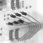
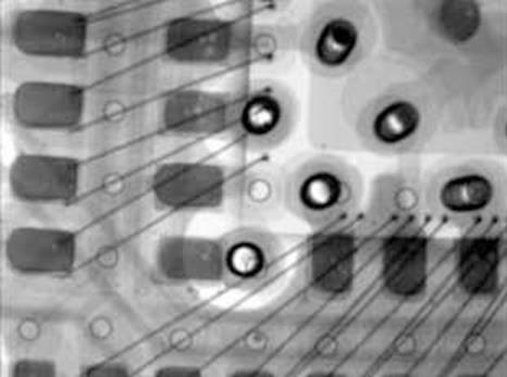
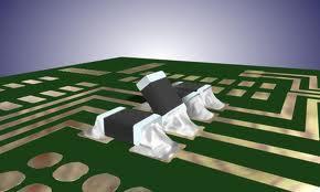
11 AXI, Automated X-ray Inspection JTAG Technologies


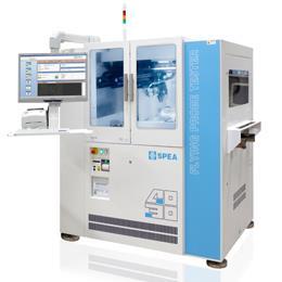
12 FP, Flying Probe 2 JTAG Technologies


13 ICT, In Circuit Test Unit under test, UUT Bed of nails Test fixture 3 JTAG Technologies

14 FT, Functional Test Rack and Stack Instrumentation controlled by a computer and dedicated software. Instrumentation: Programmable Power Supplies Generator Oscilloscope Waveform-analyzer Switching matrix etc. 4 JTAG Technologies
15 Pros & Cons Functional Test Functional Test Checks the functionality of the board - Big problem if the core is not running - Manual creation of the tests (error prone to SW-bugs) - Very difficult to diagnose, doesn t pinpoint to the exact location of the problem - Requires highly skilled engineers to find the problem - Time consuming - Expensive test 5 JTAG Technologies
16 Pros & Cons Structural Test Structural Test Checks the structure of the board (interconnects, device orientation, device values etc.) - test + Automatic generation based on the Netlist + Low cost to generate testprogram (use ATPG) + Pinpoints to the exact location of the problem if sufficient testpoints are available 6 JTAG Technologies


17 Interconnect test on a PCBA with BGA s The probes require a minimum clearance, and a typical spring force of.5n per pin to ensure good contact. 7 JTAG Technologies
18 Boundary-scan provides accessibility What is Boundary-scan and how does it work Official standard: IEEE Std JTAG Technologies

19 Boundary-scan architecture The Boundary-scan architecture is a standard implementation in many devices, such as µcontrollers, DSPs, FPGAs etc.. I/0 I/0 I/0 I/0 I/0 I/0 Core I/0 I/0 I/0 9 JTAG Technologies
20 Boundary-scan architecture Additional Testlogic and pins have been added to the device I/0 I/0 I/0 I/0 I/0 BSR Boundary-Scan Register I/0 I/0 Core I/0 I/0 TDI Bypass TDO TMS TCK TRST Optional Instruction register Controller 20 JTAG Technologies TDI Test Data In TDO Test Data Out TMS Test Mode Select TCK Test Clock TRSTTest Reset (optional)
21 Example with two Boundary-scan devices Core Core TDI BP TDO TDI BP TDO IR IR Controller Controller TMS TCK 2 JTAG Technologies
22 Goal is to test the interconnections Core Core TDI BP TDO TDI BP TDO IR IR Controller Controller TMS TCK 22 JTAG Technologies
23 TDI-TDO chains can be cascaded Core Core TDI BP IR Chains cascaded BP IR TDO Controller Controller TMS TCK 23 JTAG Technologies
24 Step : Define Testvector Core Core TDI BP BP TDO IR IR Controller Controller TMS TCK 24 JTAG Technologies
25 Step 2: Shift-in Testvector IC IC2 Core Core TDI BP IR TDO TDI BP IR TDO Controller Controller SHIFT TMS TCK Send multiple SHIFT commands to shift the testvector into the appropriate BSR cells. 25 JTAG Technologies
26 Step 3: Send UPDATE command TDI IC Core BP IR TDO TDI IC2 Core BP IR TDO Controller Controller UPDATE TMS TCK Send the UPDATE command, the testvector is driven onto the corresponding pins of IC. If the pins are soldered correctly the values on the pins will also appear on the nets. 26 JTAG Technologies
27 Step 4: Send CAPTURE command TDI IC Core BP IR 0 TDO TDI IC2 Core BP IR TDO Controller Controller CAPTURE TMS TCK The CAPTURE command senses the data on the pins and puts the values into the corresponding cells of IC2 27 JTAG Technologies
.")
28 Step 5: Shift-out captured data IC IC2 Core 0 Core TDI BP IR TDO TDI BP IR TDO Result 0 Controller Controller SHIFT TMS TCK The repeated SHIFT command shifts-out the captured vector (Result). 28 JTAG Technologies
29 Compare Result with Expected IC IC2 Core 0 Core Expected TDI BP IR TDO TDI Result BP TDO 0 IR Controller Controller TMS TCK 29 JTAG Technologies
30 Diagnose the outcome IC IC2 Core 0 Core Expected TDI BP IR TDO TDI BP IR TDO Result 0 Controller Controller TMS TCK Mismatch caused due to an open pin 30 JTAG Technologies
31 Faultdetection With the aid of Intelligent testvectors Opens Shorts SA and SA0 problems are easily detected The Intelligent testvectors are based on an Enhanced Binary Search principle. (Minimum set of Testvectors with a Maximum Testcoverage) 3 JTAG Technologies


32 Compare and Diagnose Errors are shown in inverse video. In this case the result was a 0 however a was expected. and 0 are for Input H, L and Z are for output The diagnostics pinpoints to the exact error locations 32 JTAG Technologies
33 Testing the connectivity of Non-Bscan components Bscan Non-Bscan Bscan TDI TDO Boundary-scan chain 33 JTAG Technologies
34 Testing connectivity of NAND Gate A B & Y TDI TDO Bscan A B Y Boundary-scan chain 34 JTAG Technologies Bscan Use Truthtable to stimulate the inputs and sense the outputs of the NAND-gate using the Bscan cells. A model contains information about the Truthtable.
35 Testing connectivity of RAM ADD Bscan RAM DATA Bscan Ctrl TDI TDO Boundary-scan chain Stimulate the Add/Data/Ctrl pins to write and read data from the RAM. The information on how to read/write to the memory is described in a model. 35 JTAG Technologies
36 Testing connectivity of FLASH ADD Bscan FLASH DATA Bscan Ctrl TDI TDO Boundary-scan chain A FLASH model contains all the information on how to get access to the device. 36 JTAG Technologies
37 Programming external FLASH ADD Bscan FLASH DATA Bscan Ctrl TDI TDO Boundary-scan chain The Image file gets integrated into the Bscan patterns to program the FLASH. 37 JTAG Technologies
38 Testing connectivity I/O block and Connector Bscan Bscan I/O Connector LoopBack Connector TDI Boundary-scan chain TDO Use loopback connector to test the connectivity of the I/O block and Connector 38 JTAG Technologies
39 Testing connectivity I/O block and Connector Bscan Bscan I/O Connector External Bscan device/board TDI TDO Boundary-scan chain Use an external Bscan device/board with required # of I/O pins to get full access. 39 JTAG Technologies
40 Testing connectivity serial devices I2C, SPI etc. SDA SLC Bscan I2C Bscan TDI TDO Simulating the I2C protocol on SDA and SLC givess access to the I2C device The information on how to simulate the serial protocol is defined in a model. 40 JTAG Technologies
41 Programming via the JTAG interface We ve already seen that the Boundary-scan chain can be used for Programming an on-board Flash. Some devices use the JTAG interface to get direct access to the inside of the device for programming/debug purposes. 4 JTAG Technologies
42 Programming FPGA s etc. Logic cells Interconnections JTAG Interface 42 JTAG Technologies
43 Programming FPGA s etc. JTAG Interface FPGAs use the JTAG interface to directly download the configuration file into the device. 43 JTAG Technologies
44 Programming FPGA s etc. JTAG Interface Fortunately, most of these these chips also have a Boundary-scan chain that provides direct access to the I/O pins and can be used for testing. 44 JTAG Technologies

45 Programming Embedded Flash Internal FLASH µcontroller Core JTAG Interface Many µcontrollers have internal flash that can be directly programmed via de JTAG interface 45 JTAG Technologies
46 Warning Not all devices with a JTAG interface are Boundary-scan compliant. JTAG interface JTAG interface For this type of devices a BSDL-file exists For this type of devices NO BSDL-file exists 46 JTAG Technologies
47 What is a BSDL-file The Boundary-Scan Description Language (BSDL) file is a model description of how the boundary-scan architecture is implemented in the device. The BSDL file is mandatory for the creation of Bscan applications. 47 JTAG Technologies

48 How to get BSDL files BSDL files can be downloaded from the suppliers websites Example: 48 JTAG Technologies

49 Demonstration 49 JTAG Technologies
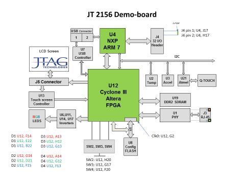
50 Blockdiagram 50 JTAG Technologies


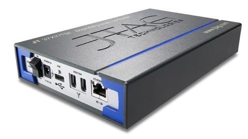
51 Full access via the TAP (Test Access Port) TAP 5 JTAG Technologies

52 JTAG Live Boundary-scan tools JTAG Live Studio is a complete Boundary-scan solution for testing, debugging and programming boards. 52 JTAG Technologies
53 JTAG Live Buzz JTAG Live Buzz provides an easy solution for debugging boards too crowded for traditional probing with scopes or logic analysers - what's more it's totally free. Buzz is ideal for electronics engineers and technicians to use in checking printed circuit boards for basic continuity and correct operation. Buzz simply uses the built-in pin access provided in boundary-scan (IEEE Std 49.) compliant devices to perform pin to pin continuity tests, drive output pins and can also sample pin activity on input pins FREE download on 53 JTAG Technologies
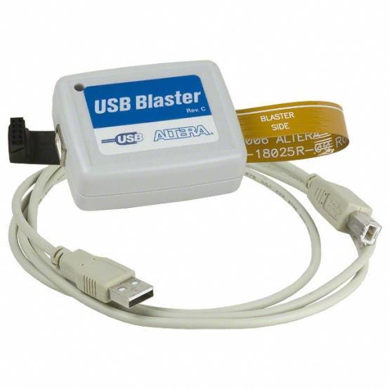
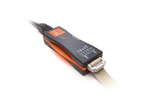
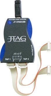
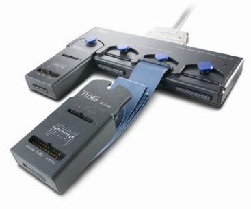

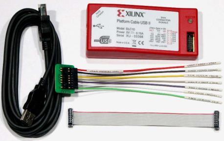
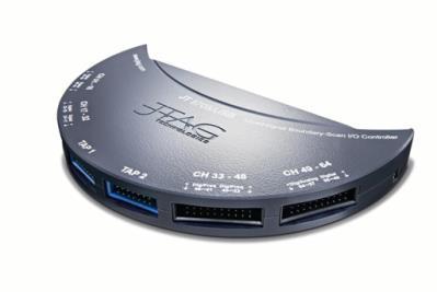
54 Supported controllers 54 JTAG Technologies
55 v 55 JTAG Technologies
7 Nov 2017 Testing and programming PCBA s
 7 Nov 207 Testing and programming PCBA s Rob Staals JTAG Technologies Email: robstaals@jtag.com JTAG Technologies The importance of Testing Don t ship bad products to your customers, find problems before
18 Nov 2015 Testing and Programming PCBA s. 1 JTAG Technologies
 8 Nov 25 Testing and Programming PCBA s JTAG Technologies The importance of Testing Don t ship bad products to your customers, find problems before they do. DOA s (Death On Arrival) lead to huge costs
16 Dec Testing and Programming PCBA s. 1 JTAG Technologies
 6 Dec 24 Testing and Programming PCBA s JTAG Technologies The importance of Testing Don t ship bad products to your customers, find problems before they do. DOA s (Death On Arrival) lead to huge costs
the Boundary Scan perspective
 the Boundary Scan perspective Rik Doorneweert, JTAG Technologies rik@jtag.com www.jtag.com Subjects Economics of testing Test methods and strategy Boundary scan at: Component level Board level System level
Introduction to JTAG / boundary scan-based testing for 3D integrated systems. (C) GOEPEL Electronics -
 GOEPEL Electronics -") Introduction to JTAG / boundary scan-based testing for 3D integrated systems (C) 2011 - GOEPEL Electronics - www.goepelusa.com Who is GOEPEL? World Headquarters: GÖPEL electronic GmbH Göschwitzer Straße
Introduction to JTAG / boundary scan-based testing for 3D integrated systems (C) 2011 - GOEPEL Electronics - www.goepelusa.com Who is GOEPEL? World Headquarters: GÖPEL electronic GmbH Göschwitzer Straße
Testing Sequential Logic. CPE/EE 428/528 VLSI Design II Intro to Testing (Part 2) Testing Sequential Logic (cont d) Testing Sequential Logic (cont d)
 Testing Sequential Logic (cont d) Testing Sequential Logic (cont d)") Testing Sequential Logic CPE/EE 428/528 VLSI Design II Intro to Testing (Part 2) Electrical and Computer Engineering University of Alabama in Huntsville In general, much more difficult than testing combinational
Testing Sequential Logic CPE/EE 428/528 VLSI Design II Intro to Testing (Part 2) Electrical and Computer Engineering University of Alabama in Huntsville In general, much more difficult than testing combinational
of Boundary Scan techniques.
 SMT TEHNOLOGY Boundary Scan Techniques for Test Coverage Improvement When discussing the JTAG protocol, most engineers immediately think of In System Programming procedures. Indeed, there are numerous
Saving time & money with JTAG
 Saving time & money with JTAG AltiumLive 2017: ANNUAL PCB DESIGN SUMMIT Simon Payne CEO, XJTAG Ltd. Saving time and money with JTAG JTAG / IEEE 1149.X Take-away points Get JTAG right from the start Use
Tools to Debug Dead Boards
 Tools to Debug Dead Boards Hardware Prototype Bring-up Ryan Jones Senior Application Engineer Corelis 1 Boundary-Scan Without Boundaries click to start the show Webinar Outline What is a Dead Board? Prototype
A Briefing on IEEE Standard Test Access Port And Boundary-Scan Architecture ( AKA JTAG )
") A Briefing on IEEE 1149.1 1990 Standard Test Access Port And Boundary-Scan Architecture ( AKA JTAG ) Summary With the advent of large Ball Grid Array (BGA) and fine pitch SMD semiconductor devices the
A Briefing on IEEE 1149.1 1990 Standard Test Access Port And Boundary-Scan Architecture ( AKA JTAG ) Summary With the advent of large Ball Grid Array (BGA) and fine pitch SMD semiconductor devices the
UNIT IV CMOS TESTING. EC2354_Unit IV 1
 UNIT IV CMOS TESTING EC2354_Unit IV 1 Outline Testing Logic Verification Silicon Debug Manufacturing Test Fault Models Observability and Controllability Design for Test Scan BIST Boundary Scan EC2354_Unit
Using the XC9500/XL/XV JTAG Boundary Scan Interface
 Application Note: XC95/XL/XV Family XAPP69 (v3.) December, 22 R Using the XC95/XL/XV JTAG Boundary Scan Interface Summary This application note explains the XC95 /XL/XV Boundary Scan interface and demonstrates
Lecture 17: Introduction to Design For Testability (DFT) & Manufacturing Test
 & Manufacturing Test") Lecture 17: Introduction to Design For Testability (DFT) & Manufacturing Test Mark McDermott Electrical and Computer Engineering The University of Texas at Austin Agenda Introduction to testing Logical
Lecture 17: Introduction to Design For Testability (DFT) & Manufacturing Test Mark McDermott Electrical and Computer Engineering The University of Texas at Austin Agenda Introduction to testing Logical
BTW03 DESIGN CONSIDERATIONS IN USING AS A BACKPLANE TEST BUS International Test Conference. Pete Collins
 2003 International Test Conference DESIGN CONSIDERATIONS IN USING 1149.1 AS A BACKPLANE TEST BUS Pete Collins petec@jtag.co.uk JTAG TECHNOLOGIES BTW03 PURPOSE The purpose of this presentation is to discuss
Section 24. Programming and Diagnostics
 Section. and Diagnostics HIGHLIGHTS This section of the manual contains the following topics:.1 Introduction... -2.2 In-Circuit Serial... -2.3 Enhanced In-Circuit Serial... -5.4 JTAG Boundary Scan... -6.5
Unit V Design for Testability
 Unit V Design for Testability Outline Testing Logic Verification Silicon Debug Manufacturing Test Fault Models Observability and Controllability Design for Test Scan BIST Boundary Scan Slide 2 Testing
BSDL Validation: A Case Study
 ASSET InterTech, Inc. Validation: A Case Study Michael R. Johnson Sr. Applications Engineer ASSET InterTech, Inc. Agilent Boundary Scan User Group Meeting December 15, 2008 About The Presenter Michael
Section 24. Programming and Diagnostics
 Section. Programming and Diagnostics HIGHLIGHTS This section of the manual contains the following topics:.1 Introduction... -2.2 In-Circuit Serial Programming... -3.3 Enhanced In-Circuit Serial Programming...
Digital Integrated Circuits Lecture 19: Design for Testability
 Digital Integrated Circuits Lecture 19: Design for Testability Chih-Wei Liu VLSI Signal Processing LAB National Chiao Tung University cwliu@twins.ee.nctu.edu.tw DIC-Lec19 cwliu@twins.ee.nctu.edu.tw 1 Outline
XJTAG DFT Assistant for
 XJTAG DFT Assistant for Installation and User Guide Version 1.0 enquiries@xjtag.com Table of Contents SECTION PAGE 1. Introduction...3 2. Installation...3 3. Quick Start Guide...3 4. User Guide...4 4.1.
CMOS Testing-2. Design for testability (DFT) Design and Test Flow: Old View Test was merely an afterthought. Specification. Design errors.
 Design and Test Flow: Old View Test was merely an afterthought. Specification. Design errors.") Design and test CMOS Testing- Design for testability (DFT) Scan design Built-in self-test IDDQ testing ECE 261 Krish Chakrabarty 1 Design and Test Flow: Old View Test was merely an afterthought Specification
Design and test CMOS Testing- Design for testability (DFT) Scan design Built-in self-test IDDQ testing ECE 261 Krish Chakrabarty 1 Design and Test Flow: Old View Test was merely an afterthought Specification
XJTAG DFT Assistant for
 XJTAG DFT Assistant for Installation and User Guide Version 2 enquiries@xjtag.com Table of Contents SECTION PAGE 1. Introduction...3 2. Installation...3 3. Quick Start Guide...4 4. User Guide...4 4.1.
Overview of BDM nc. The IEEE JTAG specification is also recommended reading for those unfamiliar with JTAG. 1.2 Overview of BDM Before the intr
 Application Note AN2387/D Rev. 0, 11/2002 MPC8xx Using BDM and JTAG Robert McEwan NCSD Applications East Kilbride, Scotland As the technical complexity of microprocessors has increased, so too has the
XJTAG DFT Assistant for
 XJTAG DFT Assistant for Installation and User Guide Version 2 enquiries@xjtag.com Table of Contents SECTION PAGE 1. Introduction...3 2. Installation...3 3. Quick Start Guide...3 4. User Guide...4 4.1.
XJTAG DFT Assistant for
 XJTAG DFT Assistant for Installation and User Guide Version 2 enquiries@xjtag.com Table of Contents SECTION PAGE 1. Introduction...3 2. Installation...3 3. Quick Start Guide...3 4. User Guide...4 4.1.
3. Configuration and Testing
 3. Configuration and Testing C51003-1.4 IEEE Std. 1149.1 (JTAG) Boundary Scan Support All Cyclone devices provide JTAG BST circuitry that complies with the IEEE Std. 1149.1a-1990 specification. JTAG boundary-scan
Based on slides/material by. Topic 14. Testing. Testing. Logic Verification. Recommended Reading:
 Based on slides/material by Topic 4 Testing Peter Y. K. Cheung Department of Electrical & Electronic Engineering Imperial College London!! K. Masselos http://cas.ee.ic.ac.uk/~kostas!! J. Rabaey http://bwrc.eecs.berkeley.edu/classes/icbook/instructors.html
Comparing JTAG, SPI, and I2C
 Comparing JTAG, SPI, and I2C Application by Russell Hanabusa 1. Introduction This paper discusses three popular serial buses: JTAG, SPI, and I2C. A typical electronic product today will have one or more
Product Update. JTAG Issues and the Use of RT54SX Devices
 Product Update Revision Date: September 2, 999 JTAG Issues and the Use of RT54SX Devices BACKGROUND The attached paper authored by Richard B. Katz of NASA GSFC and J. J. Wang of Actel describes anomalies
Y. Tsiatouhas. VLSI Systems and Computer Architecture Lab. Boundary Scan (JTAG ) 2
 2") CMOS INTEGRATE CIRCUIT EGN TECHNIUES University of Ioannina Boundary Scan Testing (JTAG ΙΕΕΕ 49 std) ept of Computer Science and Engineering Y Tsiatouhas CMOS Integrated Circuit esign Techniques VL Systems
CMOS INTEGRATE CIRCUIT EGN TECHNIUES University of Ioannina Boundary Scan Testing (JTAG ΙΕΕΕ 49 std) ept of Computer Science and Engineering Y Tsiatouhas CMOS Integrated Circuit esign Techniques VL Systems
12. IEEE (JTAG) Boundary-Scan Testing for the Cyclone III Device Family
 Boundary-Scan Testing for the Cyclone III Device Family") December 2011 CIII51014-2.3 12. IEEE 1149.1 (JTAG) Boundary-Scan Testing for the Cyclone III Device Family CIII51014-2.3 This chapter provides guidelines on using the IEEE Std. 1149.1 boundary-scan test
December 2011 CIII51014-2.3 12. IEEE 1149.1 (JTAG) Boundary-Scan Testing for the Cyclone III Device Family CIII51014-2.3 This chapter provides guidelines on using the IEEE Std. 1149.1 boundary-scan test
Remote Diagnostics and Upgrades
 Remote Diagnostics and Upgrades Tim Pender -Eastman Kodak Company 10/03/03 About this Presentation Motivation for Remote Diagnostics Reduce Field Maintenance costs Product needed to support 100 JTAG chains
JRC ( JTAG Route Controller ) Data Sheet
 Data Sheet") JRC ( JTAG Route Controller ) Data Sheet ATLAS TGC Electronics Group September 5, 2002 (version 1.1) Author : Takashi Takemoto Feature * JTAG signal router with two inputs and seven outputs. * Routing
JRC ( JTAG Route Controller ) Data Sheet ATLAS TGC Electronics Group September 5, 2002 (version 1.1) Author : Takashi Takemoto Feature * JTAG signal router with two inputs and seven outputs. * Routing
Chapter 19 IEEE Test Access Port (JTAG)
") Chapter 9 IEEE 49. Test Access Port (JTAG) This chapter describes configuration and operation of the MCF537 JTAG test implementation. It describes the use of JTAG instructions and provides information
Chapter 9 IEEE 49. Test Access Port (JTAG) This chapter describes configuration and operation of the MCF537 JTAG test implementation. It describes the use of JTAG instructions and provides information
Using IEEE Boundary Scan (JTAG) With Cypress Ultra37000 CPLDs
 With Cypress Ultra37000 CPLDs") Using IEEE 49. Boundary Scan (JTAG) With Cypress Ultra37 CPLDs Introduction As Printed Circuit Boards (PCBs) have become multi-layered with double-sided component mounting and Integrated Circuits have
Using IEEE 49. Boundary Scan (JTAG) With Cypress Ultra37 CPLDs Introduction As Printed Circuit Boards (PCBs) have become multi-layered with double-sided component mounting and Integrated Circuits have
Using the XSV Board Xchecker Interface
 Using the XSV Board Xchecker Interface May 1, 2001 (Version 1.0) Application Note by D. Vanden Bout Summary This application note shows how to configure the XC9510 CPLD on the XSV Board to enable the programming
Subjects. o JTAG Technologies (Rik Doorneweert, Area Manager) o JTAG Technologies B.V. activities o Introduction to (classic) Boundary Scan
 o JTAG Technologies B.V. activities o Introduction to (classic) Boundary Scan") Subjects o JTAG Technologies (Rik Doorneweert, Area Manager) o JTAG Technologies B.V. activities o Introduction to (classic) Boundary Scan o Grass Valley Breda(Camera division) (Khaled Sarsam, Test Automation
Subjects o JTAG Technologies (Rik Doorneweert, Area Manager) o JTAG Technologies B.V. activities o Introduction to (classic) Boundary Scan o Grass Valley Breda(Camera division) (Khaled Sarsam, Test Automation
Avoiding False Pass or False Fail
 Avoiding False Pass or False Fail By Michael Smith, Teradyne, October 2012 There is an expectation from consumers that today s electronic products will just work and that electronic manufacturers have
SignalTap Plus System Analyzer
 SignalTap Plus System Analyzer June 2000, ver. 1 Data Sheet Features Simultaneous internal programmable logic device (PLD) and external (board-level) logic analysis 32-channel external logic analyzer 166
Raspberry Pi debugging with JTAG
 Arseny Kurnikov Aalto University December 13, 2013 Outline JTAG JTAG on RPi Linux kernel debugging JTAG Joint Test Action Group is a standard for a generic transport interface for integrated circuits.
CHAPTER 3 EXPERIMENTAL SETUP
 CHAPTER 3 EXPERIMENTAL SETUP In this project, the experimental setup comprised of both hardware and software. Hardware components comprised of Altera Education Kit, capacitor and speaker. While software
XJTAG. Boundary Scan Tool. diagnosys.com
 XJTAG Boundary Scan Tool diagnosys.com XJLink Overview The XJLink is a small, portable, USB 2.0 to JTAG adapter that provides a high speed interface (480Mbps) to the JTAG chain. The small, lightweight
OpenOCD - Beyond Simple Software Debugging
 OpenOCD - Beyond Simple Software Debugging Oleksij Rempel o.rempel@pengutronix.de https://www.pengutronix.de Why I use OpenOCD? Reverse engineering and for fun This is the main motivation behind this talk
Chapter 10 Exercise Solutions
 VLSI Test Principles and Architectures Ch. 10 oundary Scan & Core-ased Testing P. 1/10 Chapter 10 Exercise Solutions 10.1 The following is just an example for testing chips and interconnects on a board.
Based on slides/material by. Topic Testing. Logic Verification. Testing
 Based on slides/material by Topic 4 K. Masselos http://cas.ee.ic.ac.uk/~kostas J. Rabaey http://bwrc.eecs.berkeley.edu/classes/icbook/instructors.html igital Integrated Circuits: A esign Perspective, Prentice
SµMMIT E & LXE/DXE JTAG Testability for the SJ02 Die
 UTMC Application Note SµMMIT E & LXE/DXE JTAG Testability for the SJ02 Die JTAG Instructions: JTAG defines seven (7) public instructions as follows: Instruction Status UTMC Code msb..lsb SµMMIT Status
EEM Digital Systems II
 ANADOLU UNIVERSITY DEPARTMENT OF ELECTRICAL AND ELECTRONICS ENGINEERING EEM 334 - Digital Systems II LAB 3 FPGA HARDWARE IMPLEMENTATION Purpose In the first experiment, four bit adder design was prepared
@DonAndrewBailey
 @DonAndrewBailey donb@isecpartners.com whois donb? whatis isec Partners? Technology is The Great Equalizer As Technology Increases, Control Decreases Examples of Emerging Technology? No, really.
PCB Test & Programming Solutions
 PCB Test & Programming Solutions from the IEEE 1149.1 Boundary-Scan Experts www.jtag.com Test and In-System Programming Solutions for Today s Problems Throughout the electronics industry, manufacturers
Programmable Logic Design I
 Programmable Logic Design I Introduction In labs 11 and 12 you built simple logic circuits on breadboards using TTL logic circuits on 7400 series chips. This process is simple and easy for small circuits.
Memec Spartan-II LC User s Guide
 Memec LC User s Guide July 21, 2003 Version 1.0 1 Table of Contents Overview... 4 LC Development Board... 4 LC Development Board Block Diagram... 6 Device... 6 Clock Generation... 7 User Interfaces...
BOARD TEST The powerful combination of flying probe test and JTAG test speeds up testing
 BOARD TEST The powerful combination of flying probe test and JTAG test speeds up testing By Olivier Artur (Alcatel CIT), Christophe Lotz (ASTER Ingénierie) and Peter de Bruyn Kops (Acugen Software, Inc.)
11. JTAG Boundary-Scan Testing in Stratix V Devices
 ecember 2 SV52-.4. JTAG Boundary-Scan Testing in Stratix V evices SV52-.4 This chapter describes the boundary-scan test (BST) features that are supported in Stratix V devices. Stratix V devices support
On-Chip Instrumentation and In-Silicon Debug Tools for SoC Dr. Neal Stollon HDL Dynamics
 On-Chip Instrumentation and In-Silicon Tools for SoC Dr. Neal Stollon HDL Dynamics neals@hdldynamics.com So What do we mean by On-Chip Instrumentation and In-Silicon? What will this talk cover An Overview
Lecture 18 Design For Test (DFT)
") Lecture 18 Design For Test (DFT) Xuan Silvia Zhang Washington University in St. Louis http://classes.engineering.wustl.edu/ese461/ ASIC Test Two Stages Wafer test, one die at a time, using probe card production
Lecture 18 Design For Test (DFT) Xuan Silvia Zhang Washington University in St. Louis http://classes.engineering.wustl.edu/ese461/ ASIC Test Two Stages Wafer test, one die at a time, using probe card production
ScanExpress JET. Combining JTAG Test with JTAG Emulation to Reduce Prototype Development Time. Ryan Jones Corelis, Inc. An EWA Technologies Company
 ScanExpress JET Combining JTAG Test with JTAG Emulation to Reduce Prototype Development Time Ryan Jones Corelis, Inc. An EWA Technologies Company What Is ScanExpress JET? A powerful combination of boundary-scan
In-System Programmability Guidelines
 In-System Programmability Guidelines May 1999, ver. 3 Application Note 100 Introduction As time-to-market pressures increase, design engineers require advanced system-level products to ensure problem-free
SµMMIT E & LXE/DXE Built-In-Self-Test Functionality for the JA01 Die
 UTMC Application Note SµMMIT E & LXE/DXE Built-In-Self-Test Functionality for the JA01 Die JTAG Instructions: JTAG defines seven (7) public instructions as follows: Instruction Status UTMC Code msb..lsb
EXOSTIV TM. Frédéric Leens, CEO
 EXOSTIV TM Frédéric Leens, CEO A simple case: a video processing platform Headers & controls per frame : 1.024 bits 2.048 pixels 1.024 lines Pixels per frame: 2 21 Pixel encoding : 36 bit Frame rate: 24
IEEE Standard (JTAG) in the Axcelerator Family
 in the Axcelerator Family") Application Note AC27 IEEE Standard 49. (JTAG) in the Axcelerator Family Introduction Testing modern loaded circuit boards has become extremely expensive and very difficult to perform. The rapid development
Application Note AC27 IEEE Standard 49. (JTAG) in the Axcelerator Family Introduction Testing modern loaded circuit boards has become extremely expensive and very difficult to perform. The rapid development
IMPROVED SIGNAL INTEGRITY IN EMBEDDED IEEE BOUNDARY-SCAN DESIGNS. Efren J. Taboada. A thesis submitted to the faculty of
 IMPROVED SIGNAL INTEGRITY IN EMBEDDED IEEE 1149.1 BOUNDARY-SCAN DESIGNS by Efren J. Taboada A thesis submitted to the faculty of Brigham Young University in partial fulfillment of the requirements for
Error connecting to the target: TMS320F28379D. 1 Error message on connecting the target.
 Error connecting to the target: TMS320F28379D 1 Error message on connecting the target. [Start: Texas Instruments XDS100v2 USB Debug Probe] Execute the command: %ccs_base%/common/uscif/dbgjtag -f %boarddatafile%
ontap BOUNDARY SCAN SOFTWARE PRODUCT FEATURES AND SCREEN TOUR FLYNN SYSTEMS CORP.
 ontap BOUNDARY SCAN SOFTWARE PRODUCT FEATURES AND SCREEN TOUR FLYNN SYSTEMS CORP. PROVIDING BOUNDARY SCAN SOLUTIONS SINCE 2000 1 ontap Product Documentation Table of Contents Introduction... 4 Overview...
Configuring FLASHlogic Devices
 Configuring FLASHlogic s April 995, ver. Application Note 45 Introduction The Altera FLASHlogic family of programmable logic devices (PLDs) is based on CMOS technology with SRAM configuration elements.
Device 1 Device 2 Device 3 Device 4
 APPLICATION NOTE 0 The Tagalyzer - A JTAG Boundary Scan Debug Tool XAPP 103 March 1, 2007 (Version 1.1) 0 3* Application Note Summary The Tagalyzer is a diagnostic tool that helps debug long JTAG boundary
Scan. This is a sample of the first 15 pages of the Scan chapter.
 Scan This is a sample of the first 15 pages of the Scan chapter. Note: The book is NOT Pinted in color. Objectives: This section provides: An overview of Scan An introduction to Test Sequences and Test
FPGA Design. Part I - Hardware Components. Thomas Lenzi
 FPGA Design Part I - Hardware Components Thomas Lenzi Approach We believe that having knowledge of the hardware components that compose an FPGA allow for better firmware design. Being able to visualise
Entry Level Tool II. Reference Manual. System Level Solutions, Inc. (USA) Murphy Avenue San Martin, CA (408) Version : 1.0.
 Murphy Avenue San Martin, CA (408) Version : 1.0.") Entry Level Tool II Reference Manual, Inc. (USA) 14100 Murphy Avenue San Martin, CA 95046 (408) 852-0067 http://www.slscorp.com Version : 1.0.3 Date : October 7, 2005 Copyright 2005-2006,, Inc. (SLS) All
Entry Level Tool II Reference Manual, Inc. (USA) 14100 Murphy Avenue San Martin, CA 95046 (408) 852-0067 http://www.slscorp.com Version : 1.0.3 Date : October 7, 2005 Copyright 2005-2006,, Inc. (SLS) All
Using SignalTap II in the Quartus II Software
 White Paper Using SignalTap II in the Quartus II Software Introduction The SignalTap II embedded logic analyzer, available exclusively in the Altera Quartus II software version 2.1, helps reduce verification
Test strategies for industrial testers for converter controls equipment
 Journal of Instrumentation OPEN ACCESS Test strategies for industrial testers for converter controls equipment To cite this article: P. Oleniuk et al View the article online for updates and enhancements.
Using on-chip Test Pattern Compression for Full Scan SoC Designs
 Using on-chip Test Pattern Compression for Full Scan SoC Designs Helmut Lang Senior Staff Engineer Jens Pfeiffer CAD Engineer Jeff Maguire Principal Staff Engineer Motorola SPS, System-on-a-Chip Design
CoLinkEx JTAG/SWD adapter USER MANUAL
 CoLinkEx JTAG/SWD adapter USER MANUAL rev. A Website: www.bravekit.com Contents Introduction... 3 1. Features of CoLinkEX adapter:... 3 2. Elements of CoLinkEx programmer... 3 2.1. LEDs description....
Keysight Technologies x1149 Boundary Scan Analyzer. Technical Overview
 Keysight Technologies x1149 Boundary Scan Analyzer Technical Overview Better Coverage, Better Diagnostics, Best-in-Class Usability Boundary scan has become an indispensable technology as engineers like
K.T. Tim Cheng 07_dft, v Testability
 K.T. Tim Cheng 07_dft, v1.0 1 Testability Is concept that deals with costs associated with testing. Increase testability of a circuit Some test cost is being reduced Test application time Test generation
A Primer: ARM Trace. Including: ETM, ETB and Serial Wire Viewer, JTAG and SWD V 2.1
 A Primer: ARM Trace Including: ETM, ETB and Serial Wire Viewer, JTAG and SWD V 2.1 Agenda Introduction How we talk to your CPU using JTAG or SWD. Trace. ETM, ETB and SWV. How are they different? Triggers,
BABAR IFR TDC Board (ITB): system design
: system design") BABAR IFR TDC Board (ITB): system design Version 1.1 12 december 1997 G. Crosetti, S. Minutoli, E. Robutti I.N.F.N. Genova 1. Introduction TDC readout of the IFR will be used during BABAR data taking to
BABAR IFR TDC Board (ITB): system design Version 1.1 12 december 1997 G. Crosetti, S. Minutoli, E. Robutti I.N.F.N. Genova 1. Introduction TDC readout of the IFR will be used during BABAR data taking to
Debugging IDT S-RIO Gen2 Switches Using RapidFET JTAG
 Titl Debugging IDT S-RIO Gen2 Switches Using RapidFET JTAG Application Note March 29, 2012 About this Document This document discusses common problems that are encountered when debugging with a board that
Using Test Access Standards Across The Product Lifecycle
 Using Test Access Standards Across The Product Lifecycle Andrew Richardson A.Richardson@enablingMNT.co.uk 1 Outline Background & Previous Work Revision - Boundary Scan Extension to ijtag IEEE1687 ijtag
JTAG Test Controller
 Description JTAG Test Controller The device provides an interface between the 60x bus on the Motorola MPC8260 processor and two totally independent IEEE1149.1 interfaces, namely, the primary and secondary
 Page 1 of 6 Follow these guidelines to design testable ASICs, boards, and systems. (includes related article on automatic testpattern generation basics) (Tutorial) From: EDN Date: August 19, 1993 Author:
LAX_x Logic Analyzer
 Legacy documentation LAX_x Logic Analyzer Summary This core reference describes how to place and use a Logic Analyzer instrument in an FPGA design. Core Reference CR0103 (v2.0) March 17, 2008 The LAX_x
FPGA Development for Radar, Radio-Astronomy and Communications
 John-Philip Taylor Room 7.03, Department of Electrical Engineering, Menzies Building, University of Cape Town Cape Town, South Africa 7701 Tel: +27 82 354 6741 email: tyljoh010@myuct.ac.za Internet: http://www.uct.ac.za
SJTAG Meeting at EBTW 2006
 SJTAG Meeting at EBTW 2006 SJTAG Fringe Meeting at EBTW 06 Wednesday 24 May, 2005 1:00 PM 3:45 PM Tanners Room Chilworth Manor, Southampton, UK Slide 1 EBTW 2006: Agenda Ben Bennetts, SJTAG Chairman: Introduction/status
Instructions. Final Exam CPSC/ELEN 680 December 12, Name: UIN:
 Final Exam CPSC/ELEN 680 December 12, 2005 Name: UIN: Instructions This exam is closed book. Provide brief but complete answers to the following questions in the space provided, using figures as necessary.
ASTRIX ASIC Microelectronics Presentation Days
 ASTRIX ASIC Microelectronics Presentation Days ESTEC, Noordwijk, 4 th and 5 th February 2004 Matthieu Dollon matthieu.dollon@astrium.eads.net Franck Koebel franck.koebel@astrium.eads.net Page 1 - ESA 4
JTAGcable II In Circuit Emulator for Atmel AVR microcontrollers. User s Guide REV 1.0. Many ideas one solution
 JTAGcable II In Circuit Emulator for Atmel AVR microcontrollers REV 1.0 User s Guide Evalu ation Board s for 51, AVR, ST, PIC microcontrollers Sta- rter Kits Embedded Web Serve rs Prototyping Boards Minimodules
Universal ByteBlaster
 Universal ByteBlaster Hardware Manual June 20, 2005 Revision 1.1 Amfeltec Corp. www.amfeltec.com Copyright 2008 Amfeltec Corp. 35 Fifefield dr. Maple, L6A 1J2 Contents Contents 1 About this Document...
SAU510-USB ISO PLUS v.2 JTAG Emulator. User s Guide 2013.
 User s Guide 2013. Revision 1.00 JUL 2013 Contents Contents...2 1. Introduction to...4 1.1 Overview of...4 1.2 Key Features of...4 1.3 Key Items of...5 2. Plugging...6 2.1. Equipment required...6 2.2.
At-speed Testing of SOC ICs
 At-speed Testing of SOC ICs Vlado Vorisek, Thomas Koch, Hermann Fischer Multimedia Design Center, Semiconductor Products Sector Motorola Munich, Germany Abstract This paper discusses the aspects and associated
DSTREAM ARM. System and Interface Design Reference. Version 4.4. Copyright ARM. All rights reserved. ARM DUI 0499E (ID091611)
") ARM DSTREAM Version 4.4 System and Interface Design Reference Copyright 2010-2011 ARM. All rights reserved. ARM DUI 0499E () ARM DSTREAM System and Interface Design Reference Copyright 2010-2011 ARM. All
ARM DSTREAM Version 4.4 System and Interface Design Reference Copyright 2010-2011 ARM. All rights reserved. ARM DUI 0499E () ARM DSTREAM System and Interface Design Reference Copyright 2010-2011 ARM. All
Enhanced JTAG to test interconnects in a SoC
 Enhanced JTAG to test interconnects in a SoC by Dany Lebel and Sorin Alin Herta 1 Enhanced JTAG to test interconnects in a SoC Dany Lebel (1271766) and Sorin Alin Herta (1317418) ELE-6306, Test de systèmes
Document Part Number: Copyright 2010, Corelis Inc.
 CORELIS Low Voltage Adapter Low Voltage Adapter Boundary-Scan Interface User s Manual Document Part Number: 70398 Copyright 2010, Corelis Inc. Corelis, Inc. 12607 Hiddencreek Way Cerritos, CA 90703-2146
System IC Design: Timing Issues and DFT. Hung-Chih Chiang
 Wireless Information Transmission System Lab. System IC esign: Timing Issues and FT Hung-Chih Chiang Institute of Communications Engineering National Sun Yat-sen University SoC Timing Issues Outline Timing
Serial FIR Filter. A Brief Study in DSP. ECE448 Spring 2011 Tuesday Section 15 points 3/8/2011 GEORGE MASON UNIVERSITY.
 GEORGE MASON UNIVERSITY Serial FIR Filter A Brief Study in DSP ECE448 Spring 2011 Tuesday Section 15 points 3/8/2011 Instructions: Zip all your deliverables into an archive .zip and submit it
Testing Digital Systems II
 Testing Digital Systems II Lecture 2: Design for Testability (I) structor: M. Tahoori Copyright 2010, M. Tahoori TDS II: Lecture 2 1 History During early years, design and test were separate The final
FPGA Design with VHDL
 FPGA Design with VHDL Justus-Liebig-Universität Gießen, II. Physikalisches Institut Ming Liu Dr. Sören Lange Prof. Dr. Wolfgang Kühn ming.liu@physik.uni-giessen.de Lecture Digital design basics Basic logic
Slide Set 14. Design for Testability
 Slide Set 14 Design for Testability Steve Wilton Dept. of ECE University of British Columbia stevew@ece.ubc.ca Slide Set 14, Page 1 Overview Wolf 4.8, 5.6, 5.7, 8.7 Up to this point in the class, we have
Training JTAG Interface
 Training JTAG Interface TRACE32 Online Help TRACE32 Directory TRACE32 Index TRACE32 Training... Debugger Training... Advanced Debugging Topics... Training JTAG Interface... 1 History... 2 Introduction...
University of Arizona January 18, 2000 Joel Steinberg Rev. 1.6
 I/O Specification for Serial Receiver Daughter Board (PCB-0140-RCV) (Revised January 18, 2000) 1.0 Introduction The Serial Receiver Daughter Board accepts an 8b/10b encoded serial data stream, operating
Department of Electrical and Computer Engineering University of Wisconsin Madison. Fall Final Examination CLOSED BOOK
 Department of Electrical and Computer Engineering University of Wisconsin Madison Fall 2014-2015 Final Examination CLOSED BOOK Kewal K. Saluja Date: December 14, 2014 Place: Room 3418 Engineering Hall