Fixed Audio Output for the K2 Don Wilhelm (W3FPR) & Tom Hammond (NØSS) v August 2009
|
|
|
- Stanley Spencer
- 6 years ago
- Views:
Transcription
1 Fixed Audio Output for the K2 Don Wilhelm (W3FPR) & Tom Hammond (NØSS) v August 2009 I have had several requests to provide a fixed audio output from the K2. After looking at the circuits that others have designed, I found that they used single ended audio input and were usually incorporated with some other circuits that were not useful to me. I already have my external Digital Modes Switchbox built to automate digital transmissions, but I still lacked the fixed audio that would allow me to position the K2 audio gain anywhere without disturbing the gain settings on my soundcard. I choose a LM386N-3 Audio Amplifier IC for its differential inputs, high available gain, small packaging, and low external parts count. The 3 version works well from the 8 volt supply in the K2. It seems not widely known that the LM386 works just fine into a high impedance loads as well as low impedance. The amplifier is directly specified for voltage gain (Av) which then gives rise to the power available once the load resistance is known. The power available increases as the resistance decreases (P = V 2 /R) but the voltage is independent of the load. After building a couple of prototypes successfully on perf-board, I talked with Tom Hammond (NØSS) at Dayton 2004 and Tom offered to lay out a small PC board for this application. This Fixed Audio Output should serve the needs of those who want fixed audio for digital modes as well as those who would like to drive a tape recorder or other audio device. The following pages provide instructions for assembling and mounting the project. NOTE (Refer to schematic on following page) The two 5.1k resistors in the Fixed AF Output circuit determine the 'fixed' level of AF output. If you wish to change the fixed level from the adapter, you may do so by replacing the bottom 5.1k resistor with a 10k potentiometer, adjusting the potentiometer to the desired level of output, measuring the value of the potentiometer, and then replacing the bottom 5.1k resistor with a fixed resistor of equivalent value to the potentiometer.

2 The schematic, parts list and board layout are shown below (Compliments of Tom Hammond).
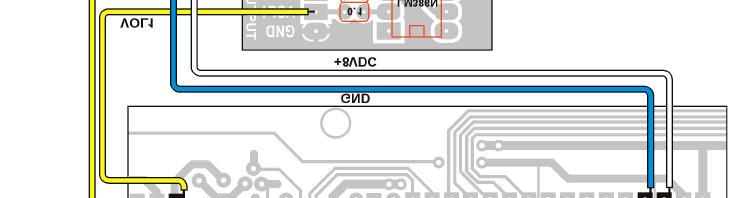
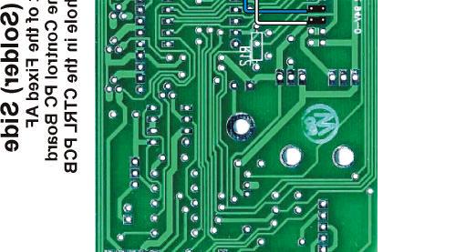
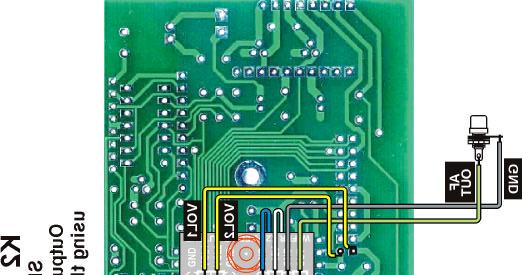
3 Assembly Instructions NOTE: All components lay flat against the PC board as illustrated on the preceding page. [ ] Insert the components into the circuit board and solder. Clip all leads close to the board surface (use flush cutters if available). BUT DO NOT trim so closely that you damage the soldered joint. [ ] Drill a 15/64" (6 mm) hole in the rear panel for the RCA jack. This hole should be centered no more than 5/16" (8 mm) below the upper edge of the panel and 3/4" (19 mm) from the left edge (near the key jack). The clearances are close use care and be certain the jack will clear the 40 meter bandpass filter inductor located nearby. [ ] De-burr the hole for the jack. [ ] Mount the RCA phone jack with its soldering lug. Orient the solder lug toward the left side panel. [ ] Prepare three (3) 2-wire cables (preferably made from colored ribbon wire so you will have color coding available to identify which wire is which). Strip 1/8" (3 mm) of insulation from both ends of each wire, twist and lightly tin the leads: - 5-1/2" (14 cm), this is the DC POWER CABLE - 3.5" (8.9 cm), this is the AF IN CABLE - 7" (18 mm), this is the AF OUTPUT CABLE [ ] If you are not using differently-colored wires for your cables, mark one edge of each cable all along its length to identify conductor #1. A permanent marking pen does an excellent job. [ ] In the next steps, solder one end of the cables prepared above to the Fixed AF Output PC Board as directed. Flush-trim any excess wire on the bottom side of the PC board. - Solder the #1 lead of the DC POWER cable to the "+12V" pad. - Solder the #2 lead of the DC POWER cable to the adjacent "GND" pad. - Solder the #1 lead of the AF IN cable to the VOL1 pad. - Solder the #2 lead of the AF IN cable to the VOL2 pad. - Solder the #1 lead of the AF OUTPUT cable to the "OUT" pad. - Solder the #2 lead of the AF OUTPUT cable to the adjacent "GND" pad. AF OUTPUT CABLE CONNECTIONS [ ] Solder the #1 conductor of the AF OUTPUT cable to the center terminal of the RCA jack. NOTE: The output may be attached to the microphone jack instead of a rear RCA jack choose an unused pin and remove any jumper for that pin from the mic configuration header. You may then attach the output to that mic pin (use a single mating plug to the configuration header so you can disconnect it) [ ] Solder the remaining conductor to the grounded solder lug of the RCA jack. [ ] Remove the Control Board from the K2 and place it solder side up and with the edge containing the pins that connect to the RF board closest to you.
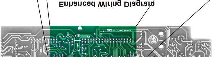
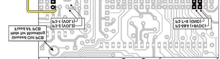
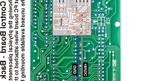
4 Refer to the illustrations on the next two pages for the following steps. DC POWER CABLE CONNECTIONS [ ] Locate P2 pins 5 & 6 (+8 volts) and solder the #1 conductor of the DC POWER cable to this pin. [ ] Locate P2 pins 7 & 8 (ground) and solder conductor #2 to it. AF INPUT CABLE CONNECTIONS [ ] Locate P3 pin 1 (VOL1) and solder conductor #1 of the AF INPUT cable to it. [ ] Locate P3 pin 2 (VOL2) and solder conductor #2 to it. FINAL ASSEMBLY [ ] Just to the right of the left-hand Control PCB mounting hole is an unused hole which will accept a 4-40 screw. (See illustrations at the end of this document). [ ] Insert (from the FRONT side of the CTRL PC board) a 4-40 X 1/2" long screw into the unused mounting hole identified in the step above. [ ] From the back side of the CTRL PC board, slip a #4 lock-washer over the screw and secure in place with a 4-40 nut. [ ] Install the Fixed AF Output PC board, a #4 lock-washer and a 4-40 nut. Position the Fixed AF PC board as shown in the illustrations at the end of this document and secure the board in place. [ ] ENSURE that none of the soldered connections on the back side of the Fixed AF Output PC board can come into contact with any of the component leads on the back side of the CTRL PC board. Trim lead lengths (on either board) if necessary. And consider adding a thin cardboard 'insulator' to the back of the Fixed AF PC board if there continues to be a potential problem. If a potential shorting problem exists, and if space permits, you may add an additional 4-40 nut (or additional lock-washers) between the Fixed AF Output PC board and the CTRL PCB to increase the board-to-board spacing. [ ] Carefully route the DC POWER and AF INPUT cables over the edge of and behind the Fixed AF Output PC board and, if the AF OUTPUT cable is to be routed to the back panel, be sure to route it around the END of the CTRL PC board in order to prevent pinching of the AF OUTPUT wires. [ ] Reinstall the CTRL PC board, taking care not to catch or pinch any of the newly added wiring. [ ] Replace the top cover of the K2 and apply power to confirm normal operation of the radio. [ ] Connect a jumper cable from the new Fixed AF Output jack to your digital (or recording) equipment to confirm proper operation of the Fixed AF Output adapter.

5

6
7
NewScope-7A Operating Manual
 2016 SIMMCONN Labs, LLC All rights reserved NewScope-7A Operating Manual Preliminary May 13, 2017 NewScope-7A Operating Manual 1 Introduction... 3 1.1 Kit compatibility... 3 2 Initial Inspection... 3 3
MONO AMPLIFIER KIT ESSENTIAL INFORMATION. Version 2.2 CREATE YOUR OWN SPEAKER DOCK WITH THIS
 ESSENTIAL INFORMATION BUILD INSTRUCTIONS CHECKING YOUR PCB & FAULT-FINDING MECHANICAL DETAILS HOW THE KIT WORKS CREATE YOUR OWN SPEAKER DOCK WITH THIS MONO AMPLIFIER KIT Version 2.2 Build Instructions
MUK REAR PANEL ASSEMBLY ASSEMBLY INSTRUCTIONS
 Rev B. 13 August 2017 ASSEMBLY INSTRUCTIONS The Midnight Ultimate Keyer (MUK) consists of two functional assemblies: Rear Panel containing the interface and power connectors. Front Panel containing the
Multi-Key v2.4 Multi-Function Amplifier Keying Interface
 Multi-Key v2.4 Multi-Function Amplifier Keying Interface ASSEMBLY & OPERATION INSTRUCTIONS INTRODUCTION The Harbach Electronics, LLC Multi-Key is a multi-function external device designed for the safe
LED Backlight for Technics amplifiers
 LED Backlight for Technics amplifiers Technics SE-A900S Technics SE-A900SM2 Technics SE-A909S Technics SE-A1000 Technics SE-A1000M2 Technics SE-A1010 Rev. 1.2 B Description The LED module is designed to
Building a MidiBox LCD Cable
 Building a MidiBox LCD Cable By Jim Henry, 3-Apr-2004 An LCD panel may be connected to the Core module by a 16 conductor flat ribbon cable. A 16 pin insulation displacement connector (IDC) terminates one
Ten-Tec (865) Service Department:(865)
 Service Department:(865)") Ten-Tec (865) 453-7172 Service Department:(865) 428-0364 Installation Instructions for Ten-Tec Jupiter AT538K Tuner Kit The installation of the AT538K is divided into two steps. The first step is to reprogram
Ten-Tec (865) 453-7172 Service Department:(865) 428-0364 Installation Instructions for Ten-Tec Jupiter AT538K Tuner Kit The installation of the AT538K is divided into two steps. The first step is to reprogram
PR-101 STEREO PREAMPLIFIER Phono Preamp ASSEMBLY MANUAL
 PR-101 STEREO PREAMPLIFIER Phono Preamp ASSEMBLY MANUAL 2016 AkitikA LLC All rights reserved Revision 1p18 March 12, 2016 Page 1 of 24 Table of Contents Table of Contents... 2 Table of Figures... 2 Section
Mal-2 assembly guide v1.0
 Mal-2 assembly guide v.0 SONIC POTIONS Schematic and BOM The BOM can be found on Google Docs Prepare the PCB Separate the PCBs using some pliers. PCB We start with the lower PCB and assemble it beginning
DEM 9ULNACK 3.4 GHz. PHEMT LNA amplifier complete kit assembly guide
 DEM 9ULNACK 3.4 GHz. PHEMT LNA amplifier complete kit assembly guide SPECIFICATIONS Noise Figure: < 0.8 db Gain: > 15 db Frequency Range: 3400-3500 MHz Input Voltage: 7-16 VDC Description: The 9ULNACK
Tube Cricket Build Guide
 Tube Cricket Build Guide The Tube Cricket is a small-wattage amp that puts out about 1 watt of audio power. With a 12AU7 tube-preamp and a JRC386 power amp, the Tube Cricket gives you great tone in a compact
Etherwave Plus Field Upgrade Instructions
 Etherwave Plus Field Upgrade Instructions The Etherwave Plus Field Upgrade is an advanced project for upgrading a standard Moog Music Etherwave theremin to the Etherwave Plus. The new features of the Etherwave
Atari PICO Composite Mod Board Installation Instructions:
 Atari PICO Composite Mod Board Installation Instructions: Installation Guide 6 Switch Atari 2600 6 Switch Video Mod Installation Guide Disclaimer: I am not responsible for any damage done to your Atari.
On-screen display signal strength meter Version 1.02
 OSD-SSM On-screen display signal strength meter Version 1.02 Copyright 2000 Intuitive Circuits, LLC D escription OSD-SSM is an on-screen display overlay board with analog to digital circuitry which continuously
VU-1 VU Meter Kit Volume Unit Meter
 VU-1 VU Meter Kit Volume Unit Meter Simplicity Counts, Detail Matters. No part of this document may be reproduced, either mechanically or electronically, posted online on the Internet, in whole or in part,
HN Connectors. Automatic Connector. Introduction. Contents. 631/ FAX 631/
 Connectors Introduction 2004 Automatic Connector. All rights reserved. pdf 1.0 4-13-04 Contents Specifications........................... 2 Straight Cable Plugs...................... 3 Right Angle Cable
How To Build Megavolt s Small Buffered JTAG v1.2
 How To Build Megavolt s Small Buffered JTAG v1.2 Abstract A JTAG cable should be considered mandatory equipment for any serious tester. It provides a means to backup the information in the receiver and
INSTALLATION INSTRUCTIONS FOR
 INSTALLATION INSTRUCTIONS FOR MODEL 2240LED www.sportablescoreboards.com 1 Table of Contents 8 X 7 INDOOR SCOREBOARD... 3 THE SCOREBOARD SYSTEM SHOULD INCLUDE THE FOLLOWING PARTS:... 3 INSTRUCTIONS FOR
Industrial Monitor Update Kit
 Industrial Monitor Update Kit (Bulletin Number 6157) Installation Instructions 2 Table of Contents Table of Contents Industrial Monitor Update Kit... 3 Overview... 3 Part 1 - Initial Preparation... 5 Part
DIY Guide - Building Franky v1.1, the SEGA Audio and Videocard for MSX
 DIY Guide - Building Franky v1.1, the SEGA Audio and Videocard for MSX 2015 FRS & MSXpró. Translation by FRS and Supersoniqs. Table of Contents Introduction... 3 Materials needed... 3 Audio volume boost...
Nutube.US. 6P1 Evaluation Board. User Manual
 Nutube.US 6P1 Evaluation Board User Manual Introduction The 6P1 Evaluation Board (EVB) is a vehicle for testing and evaluating the Korg Nutube 6P1 dual triode in audio circuits. This product is designed
Panzer 3.0 Assembly Instructions & Checklist
 Panzer 3.0 Assembly Instructions & Checklist Parts Included & Preparation Legend A. 5x Silver M4 Aluminum Screws B. 4x 10-24 Screws C. 8x 4-40 Pan head Screws D. 2x 4-40 Flat head Screws E. 2x 4-40 Nuts
Nixie Clock Type Frank 3
 Assembly Instructions And User Guide Nixie Clock Type Frank 3 Software version: 7R PCB Version: 11 April 09-1 - 1. INTRODUCTION 1.1 About the clock Nixie clock type Frank 3 is a compact design with all
DIY KIT MHZ 8-DIGIT FREQUENCY METER
 This kit is a stand-alone frequency meter capable of measuring repetitive signals up to a frequency of 50MHz. It has two frequency ranges (15 and 50 MHz) as well as two sampling rates (0.1 and 1 second).
N3ZI Digital Dial Manual For kit with Serial LCD Rev 3.04 Aug 2012
 N3ZI Digital Dial Manual For kit with Serial LCD Rev 3.04 Aug 2012 Kit properly assembled and configured for Standard Serial LCD (LCD Not yet connected) Kit Components Item Qty Designator Part Color/Marking
Total solder points: 123 Difficulty level: beginner 1. advanced AUDIO ANALYZER K8098. audio gea Give your. . high-tech ILLUSTRATED ASSEMBLY MANUAL
 Total solder points: 123 Difficulty level: beginner 1 2 3 4 5 advanced AUDIO ANALYZER K8098 ra audio gea Give your. look high-tech ILLUSTRATED ASSEMBLY MANUAL H8098IP-1 Features & Specifications Features
+41 * 2 db. GENERAL The Shure M675 Broadcast Production Master is designed for use in conjunction with a Shure M67 or
 2 2 2 HARTREY AVE., EVANSTON, IL. 6 0 2 0 4 U.S.A. GENERAL The Shure M675 Broadcast Production Master is designed for use in conjunction with a Shure M67 or M67-2E Professional Microphone Mixer, M63 Audio
DL-1A. RF dummy load - 50Ω 20W. Assembly manual. Last update: May 1, Thank you for constructing the DL-1A dummy load kit
 DL-1A RF dummy load - 50Ω 20W Assembly manual Last update: May 1, 2016 ea3gcy@gmail.com Updates and news at: www.qsl.net/ea3gcy Thank you for constructing the DL-1A dummy load kit Have fun assembling it
AUDIO ROOF KIT P/N , , APPLICATION BEFORE YOU BEGIN KIT CONTENTS. Instr Rev Page 1 of 6
 AUDIO ROOF KIT P/N 2882064, 2882065, 2882066 APPLICATION Verify accessory fitment at Polaris.com. BEFORE YOU BEGIN Read these instructions and check to be sure all parts and tools are accounted for. Please
Automatic Connector MHV Connectors MHV Introduction MHV series connectors Contents Polarized mating interfaces Anti-Rock mating interfaces
 Automatic s 2004 Automatic. All rights reserved. pdf 1.0 3-18-04 Contents Specifications........................... 2 Straight Cable Plugs...................... 3 Right Angle Cable Plugs...................
Build Your Own Clone Super 8 Kit Instructions
 Build Your Own Clone Super 8 Kit Instructions Warranty: BYOC, Inc. guarantees that your kit will be complete and that all parts and components will arrive as described, functioning and free of defect.
12G Broadcast connectors
 12G Broadcast connectors Delivering 12G in a single punch www.coax-connectors.com Welcome to COAX 12G BNC Plug return loss COAX Connectors Ltd is a leading UK designer, manufacturer and supplier of high
Bas Gialopsos Atari PureVideo Encoder Module 2600VECr5.2
 Bas Gialopsos 2014 Atari PureVideo Encoder Module 2600VECr5.2 Table of Contents Description Disclaimer Technical and Signal Identification Installation Instructions Tools Required Caution Installation
COLOUR CHANGING USB LAMP KIT
 TEACHING RESOURCES SCHEMES OF WORK DEVELOPING A SPECIFICATION COMPONENT FACTSHEETS HOW TO SOLDER GUIDE SEE AMAZING LIGHTING EFFECTS WITH THIS COLOUR CHANGING USB LAMP KIT Version 2.1 Index of Sheets TEACHING
H2633IP-1 RELAY CARD K2633
 H2633IP-1 RELAY CARD K2633 Control up to 4 high-power circuits from a low-power drive circuit. Features & Specifications The connection of a few relays to the outputs of an electronic circuit might be
AT-AUTO (tm) QRO Keyline Upgrade Kit Installation Manual
 QRO Keyline Upgrade Kit Installation Manual") AT-AUTO (tm) QRO Keyline Upgrade Kit Installation Manual P.O. Box 341543 Beavercreek, Ohio 45434 5 September, 2015 Copyright 2015 ii Contents 1 Introduction 2 1.1 General Description and Purpose........................
AT-AUTO (tm) QRO Keyline Upgrade Kit Installation Manual P.O. Box 341543 Beavercreek, Ohio 45434 5 September, 2015 Copyright 2015 ii Contents 1 Introduction 2 1.1 General Description and Purpose........................
OPERATION NOTES FOR PSIDEX AUDIO PGP-1A PRE-AMPLIFIER DESCRIPTION INSTALLATION
 OPERATION NOTES FOR PSIDEX AUDIO PGP-1A PRE-AMPLIFIER DESCRIPTION The Psidex Audio Laboratory PGP- 1A is a vacuum tube based microphone preamp and program line amplifier designed to provide solid, robust
N3ZI Digital Dial Manual For kit with Backlit LCD Rev 4.00 Jan 2013 PCB
 N3ZI Digital Dial Manual For kit with Backlit LCD Rev 4.00 Jan 2013 PCB Kit Components Item Qty Designator Part Color/Marking PCB 1 LCD Display 1 LCD 1602 Volt Regulator 1 U1 78L05, Black TO-92 Prescaler
Sega MegaDrive 1 RGB Bypass Installation Guide Rev 1.1
 Sega MegaDrive 1 RGB Bypass Installation Guide Rev 1.1 This step by step guide describes the Installation of the open source Voultar RGB Bypass Amplifier board for the original SEGA MegaDrive/Genesis 1.
RoHS. Atma-Sphere Music Preamplifier. model P-2 OWNER'S MANUAL. Please study this document carefully before using equipment
 1742 Selby Av. St. Paul, MN 55104 651 690 2246 atma sphere.com Atma-Sphere Music Preamplifier model P-2 OWNER'S MANUAL Please study this document carefully before using equipment RoHS CONGRATULATIONS!
DS1 Cross-Aisle Panel
 DS1 Cross-Aisle Panel Model 005-0005-0100 Installation Guide 1.1 Overview 1.1.1 Inspection Compare the contents of the DS1 Cross-Aisle Panel shipping container with the packing list. Call Telect if anything
TKEY-K16. Touch CW automatic electronic keyer. (No moving parts no contacts) Assembly manual. Last review: March 15, 2018
 Assembly manual. Last review: March 15, 2018") TKEY-K16 Touch CW automatic electronic keyer (No moving parts no contacts) Assembly manual Last review: March 15, 2018 Commands and use manual of the K16 and Updates and news: www.ea3gcy.com Thanks for
TKEY-K16 Touch CW automatic electronic keyer (No moving parts no contacts) Assembly manual Last review: March 15, 2018 Commands and use manual of the K16 and Updates and news: www.ea3gcy.com Thanks for
Elecraft KXAT2 Automatic Antenna Tuner Installation Instructions
 Elecraft KXAT2 Automatic Antenna Tuner Installation Instructions Revision A, May 23, 2016 E740294 Copyright 2016, Elecraft, Inc. All Rights Reserved Introduction The KXAT2 internal automatic antenna tuner
COHERENCE ONE PREAMPLIFIER
 COHERENCE ONE PREAMPLIFIER OWNER S MANUAL TABLE OF CONTENTS Introduction Features Unpacking Instructions Installation Phono Cartridge Loading Basic Troubleshooting Technical Specifications Introduction
UAV Ultimate Atari Video A7800
 UAV Ultimate Atari Video A7800 Basic Install guide because this is really easy mod to do! The UAV is a wonderful piece of tech for what it can do. To summarize, the UAV is a replacement video encoder and
SONOSAX SX-PR OPERATOR'S MANUAL
 SONOSAX SX-PR OPERATOR'S MANUAL Manual copyright 1989 - Gary J. Louie Sonosax is a trademark of Jacques Sax Edition 2.1 OVERVIEW The Sonosax SX-PR series portable stereo audio mixers are designed for jobs
In-Wall Control Mount for ipod Touch
 In-Wall Control Mount for ipod Touch INTRODUCTION The Mirage KP-iOS is an in-wall system that allows ipod touch (4th generation) to become a semi-permanent fixture in your wall. The system allows you to
Field Service Procedure Replacement GACP Control Panel Kit, ST24
 1. Brief Summary: Troubleshooting document for diagnosing a fault with and replacing the Graphic Antenna Control Panel (GACP) for the ST24 antenna. 2. Checklist: Verify Power to the GACP Verify Communications
QUIZ BUZZER KIT TEACHING RESOURCES. Version 2.0 WHO ANSWERED FIRST? FIND OUT WITH THIS
 TEACHING RESOURCES SCHEMES OF WORK DEVELOPING A SPECIFICATION COMPONENT FACTSHEETS HOW TO SOLDER GUIDE WHO ANSWERED FIRST? FIND OUT WITH THIS QUIZ BUZZER KIT Version 2.0 Index of Sheets TEACHING RESOURCES
PowerBook G4 Aluminum 12" GHz LCD panel upgrade
 PowerBook G4 Aluminum 12" 1-1.5 GHz LCD panel upgrade Upgrade a 1400x1050 LCD panel. Written By: martin ifixit CC BY-NC-SA www.ifixit.com Page 1 of 18 INTRODUCTION The original LCD 1024x768 resolution
Technical Information Bulletin
 June 4, 2001 #TIB0003 Units Affected: Model Serial Numbers Model Serial Numbers SVT-2PRO T2PDxxxxxxxxx SVTAV AXVDxxxxxxxxx ATLDxxxxxxxxx BJIDMAxxxxxxx SVT-2PROJ T2PJxxxxxxxxx SVTAVJ BAHJxxxxxxxxx ATLJxxxxxxxxx
Technical Specifications
 INSTALLATION SHEET AND OPERATORS MANUAL General Description: The is a mixer/preamplifier that includes 6 channels that each include a microphone input at screw terminals and an aux input at an RCA jack.
APPLIANCES /// MTA, CST-100 II AND SL-156 CONNECTORS. CONNECTORS/ APPLIANCES MTA, CST-100 II and SL-156 Connectors
 PPLINCES /// MT, CST-100 II ND SL-156 CONNECTORS CONNECTORS/ PPLINCES MT, CST-100 II and SL-156 Connectors Contents Introduction This catalog has been designed to assist you, our customer, identify products
ASSEMBLY, INSTALLATION, AND REMOVAL OF CONTACTS AND MODULES
 ASSEMBLY, INSTALLATION, AND REMOVAL OF CONTACTS AND MODULES FOR 75 OHM AND 75 OHM HD COAXIAL CONTACTS AND MODULES Table of Contents SECTION 1 RECEIVER CONTACT ASSEMBLY INSTRUCTIONS SECTION 2 ITA CONTACT
PART. Maxim Integrated Products 1
 9-646; Rev 0; /00 General Description The MAX94 evaluation kit (EV kit) is assembled with a MAX94 and the basic components necessary to evaluate the -bit analog-to-digital converter (ADC). Connectors for
Documentation VFD clock 8 a clock
 Documentation VFD clock 8 a clock This documentation is protected by our copyright. It must not be used for commercial purposes. Congratulations on your purchase of your VFD clock. To guarantee success
[ Photos ] [ Wares ] [ Library ] [ Dave's Web ] [ Matt's Web ] Wares [ SWISH ] [ Simple Search ] [ Trunk Calc ]
![[ Photos ] [ Wares ] [ Library ] [ Dave's Web ] [ Matt's Web ] Wares [ SWISH ] [ Simple Search ] [ Trunk Calc ]](/thumbs/85/91698811.jpg "[ Photos ] [ Wares ] [ Library ] [ Dave's Web ] [ Matt's Web ] Wares [ SWISH ] [ Simple Search ] [ Trunk Calc ]") [ Photos ] [ Wares ] [ Library ] [ Dave's Web ] [ Matt's Web ] Wares [ SWISH ] [ Simple Search ] [ Trunk Calc ] Realistic PRO-2006 Hardware Modifications Note Edited on January 1st, 1970, 00:00 UT. Improper
[ Photos ] [ Wares ] [ Library ] [ Dave's Web ] [ Matt's Web ] Wares [ SWISH ] [ Simple Search ] [ Trunk Calc ] Realistic PRO-2006 Hardware Modifications Note Edited on January 1st, 1970, 00:00 UT. Improper
RAKK dac. RAKK dac Mark IV. RAKK dac Mark IV. Assembly and Installation Manual
 RAKK dac RAKK dac Mark IV RAKK dac Mark IV Assembly and Installation Manual Version 1.3 2013-2014 Raleigh Audio version Use this manual with RAKK dac Mark IV v 2.0, which is marked on the board. Required
Product Manual MNX10015 / REV C MODEL SB142, SB242. Dual Output Series Switch Boxes
 Product Manual MNX10015 / REV C MODEL SB142, SB242 Dual Output Series Switch Boxes Contents Section I Overview Introduction.... 2 Description... 2 Section II Installation Mounting... 3 Electrical Connections...
What is the E560? Connecting to the power supply
 PAGE 1 E560 Deflector Shield DIY Kit www.synthtech.com/euro/e560 What is the E560? The Synthesis Technology E560 is a combination frequency shifter, phaser and ring modulator. The audio is mono in, and
RSL MusicPower Plug-In Installation Manual For Naim NAC 72 Preamp
 RSL MusicPower Plug-In Installation Manual For Naim NAC 72 Preamp (Updated to reflect the adjustable gain output boards Z200V) www.ryansoundlab.com RSL MusicPower Plug-In Installation Manual for Naim NAC
Description: Major features and benefits
 July 2011 DFMC DMC(V) Description: Phoenix Contact introduces a new line of stacked headers and plugs that provide a higher density application than previously available in a European-style terminal block.
Satellite Dish Installation Manual (Ver. 2) 1
 1") Satellite Dish Installation Manual Provided by DiscoverNet, Inc. Satellite Dish Installation Manual (Ver. 2) 1 Table of Contents Section 1: Introduction Page 3 Section 2: Recommended Tools and Materials
Satellite Dish Installation Manual Provided by DiscoverNet, Inc. Satellite Dish Installation Manual (Ver. 2) 1 Table of Contents Section 1: Introduction Page 3 Section 2: Recommended Tools and Materials
INSTALLATION INSTRUCTIONS FOR. MODEL 2230LED
 INSTALLATION INSTRUCTIONS FOR MODEL 2230LED www.sportablescoreboards.com 1 Table of Contents MODEL 2230LED... 3 8 X 4 INDOOR SCOREBOARD... 3 THE SCOREBOARD SYSTEM SHOULD INCLUDE THE FOLLOWING PARTS:...
Hamcrafters K44 CW Keyboard/Reader Kit Assembly Guide Revision A.0
 Introduction Figure 1 Assembled K44 This document will describe how to assemble and test a K44 Kit. The assembly requires reasonably good soldering skill. Before you start working, gather the following
Christmas LED Snowflake Project
 Christmas LED Snowflake Project Version 1.1 (01/12/2008) The snowflake is a follow-on from my Christmas star project from a few years ago. This year I decided to make a display using only white LEDs, shaped
TNC Connectors. RF Coax Connectors. Product Facts
 Product Facts Hex Crimp and Connectors 50 and 75 ohm commercial versions available Provides excellent performance at frequencies up to 7 GHz ow cost commercial type available type is smaller and lighter
Pixie Construction Notes
 Pixie Construction Notes PCB V2a February 4 th 2015 Please note that this document is still currently under revision and we apologise for any errors or omissions. Readers should feel free to e-mail any
A 100-watt Compact Z-Match Antenna Tuner By Phil Salas AD5X
 A 100-watt Compact Z-Match Antenna Tuner By Phil Salas AD5X I ve been reading about Z-Match antenna tuners for quite awhile now. The nice thing about the Z-Match tuner is that it will match just about
MAX2660/MAX2661/MAX2663/MAX2671 Evaluation Kits
 9-382; Rev ; 9/99 MAX2660/MAX266/MAX2663/MAX267 General Description The MAX2660/MAX266/MAX2663/MAX267 evaluation kits simplify evaluation of the MAX2660/MAX266/ MAX2663/MAX267 upconverter s. They enable
SUBCARRIER TRANSFER FILTER INSTRUCTION BOOK IB622702
 SCF611S SUBCARRIER TRANSFER FILTER INSTRUCTION BOOK IB622702 SCF611S SUBCARRIER TRANSFER FILTER TABLE OF CONTENTS PAGE SHIPPING INSPECTION 2 MODULE CONFIGURATION 2 INSTALLING MODULES 2-3 CABLING 3 FRONT
G4HUP Panoramic Adaptor Installation TS2000
 G4HUP Panoramic Adaptor Installation TS2000 These instruction cover installation of the PAT board in the 2 nd IF of the TS2k 10.695MHz this gives access to all receiver options on the main receiver, including
Installation Manual for New or Retrofit Installations
 Installation Manual for New or Retrofit Installations Release Date: 24-August-2015 c Able Applied Technologies LTD. READ THE ENTIRE MANUAL COMPLETELY AND CAREFULLY BEFORE STARTING BEFORE YOU BEGIN ASSEMBLY
ANTUMBRA FADE MANUAL
 ANTUMBRA FADE MANUAL TABLE OF CONTENTS 01. INSTALLATION 4 02. BACK 5 03. FRONT 6 04. USE 7 05. LINK 8 06. BILL OF MATERIALS 9 07. BUILD NOTES 10 08. BACK 11 09. FRONT 14 10. MODIFICATION 15 11. FINISHED
FSM User Guide Page 1 of 28
 FSM User Guide Page 1 of 28 Field Strength Meter User Guide and Kit Assembly Instructions PCB V1.1 Important: Always use or print this document in colour as there are references to the colours of components.
Bill of Materials: Super Simple Water Level Control PART NO
 Super Simple Water Level Control PART NO. 2169109 Design a simple water controller in which electrodes are required to sense high and low water levels in a tank. Whenever the water level falls below the
PC BOARD MOUNT DISPLAYS
 PC BOARD MOUNT DISPLAYS The Trusted Source for Innovative Control Solutions 1-717-767-6511 891 QUICK Specs Counters LCD DISPLAY SUB-CUB 1 & 2 SUB-CUB 2-8A SUB-CUB D SUB-CUB T Description Count Indication
SUHNER QMA SUBMINIATURE CONNECTORS
 SUHNER QMA SUBMINIATURE CONNECTORS Description Content Page SUHNER QMA coaxial connectors are available with 50 Ω impedance. The frequency range extends to 11 GHz, depending on the connector and cable
E4200 Antenna Installation Instructions: 1. Soldering required (here is the list of tools you will need)
") Thank you for purchasing the 6 Antenna Mod Kit for your Linksys router. First we will show you how to install the antennas for your router. Next we will teach you how to setup the DD-WRT firmware which
Thank you for purchasing the 6 Antenna Mod Kit for your Linksys router. First we will show you how to install the antennas for your router. Next we will teach you how to setup the DD-WRT firmware which
ADD AN AUDIO MESSAGE TO YOUR PRODUCT WITH THIS RECORD & PLAYBACK KIT
 ADD AN AUDIO MESSAGE TO YOUR PRODUCT WITH THIS RECORD & PLAYBACK KIT BUILD INSTRUCTIONS Before you start take a look at the Printed Circuit Board (PCB). The components go in the side with the writing on
ImproX (TRT) Twin Remote Terminal INSTALLATION MANUAL
 Twin Remote Terminal INSTALLATION MANUAL") SPECIFICATIONS MODEL NUMBER: XRT910-0-0-GB-XX XRT911-0-0-GB-XX XTT911-0-0-NN-XX IMPROX TRT ImproX (TRT) Twin Remote Terminal INSTALLATION MANUAL Working Environment XRT910-0-0-GB-XX... (Aluminium Extruded
SPECIFICATIONS MODEL NUMBER: XRT910-0-0-GB-XX XRT911-0-0-GB-XX XTT911-0-0-NN-XX IMPROX TRT ImproX (TRT) Twin Remote Terminal INSTALLATION MANUAL Working Environment XRT910-0-0-GB-XX... (Aluminium Extruded
Nixie Clock Type Frank 2 Z570M
 Assembly Instructions And User Guide Nixie Clock Type Frank 2 Z570M Software version: 7R PCB Revision: 11 April 09-1 - 1. INTRODUCTION 1.1 About the clock Nixie clock type Frank 2 is a compact design with
Main PCB (The small one)
") Thanks for choosing our kits! This manual is written taking with the problems that we usually find in our workshops in mind. Also the order is meant to make assembly as easy as possible. Some steps are
Thanks for choosing our kits! This manual is written taking with the problems that we usually find in our workshops in mind. Also the order is meant to make assembly as easy as possible. Some steps are
TR-Plus T/R Switch Assembly and Operation Manual. Introduction
 TR-Plus T/R Switch Assembly and Operation Manual Revised: 7 February 2015 2015 Tucson Amateur Packet Radio Corporation Introduction The TAPR TR-Plus is a transmit/receive ( T/R ) switch that connects a
Galilean Moons. dual amplitude transmutator. DIY ASSEMBLY MANUAL v1.02
 Galilean Moons dual amplitude transmutator DIY ASSEMBLY MANUAL v1.02 Contents Contents... 2 Introduction... 3 Eurorack Kit Assembly... 4 Resistors... 4 IC Sockets... 5 Ceramic/Film Capacitors... 5 Transistors
ASSEMBLING. the. ECEbot. Printed Circuit Board: Part Three. Due Date. The Part Three assembly steps must be completed prior to:
 ASSEMBLING the ECEbot Printed Circuit Board: Part Three Due Date The Part Three assembly steps must be completed prior to: Prepared by R.C. Maher September 2008 Copyright 2008 Department of Electrical
Installation Note. Agilent 89441A Option AYC Installation Kit
 Installation Note Agilent 89441A Option AYC Installation Kit Part Number: 89441-90074 Printed in USA February 2002 Notice. The information contained in this document is subject to change without notice.
Cable ISOBUS Active Termination
 ISOBUS Retrofit Kit Ag Leader Technology Note: Indented items indicate parts included in an assembly listed above Part Name/Description Part Number Quantity ISOBUS Retrofit Kit 4100843 1 Hex Head Bolt
MACH3 LaserAce Installation Manual Revision 1. MACH3 LaserAce Installation Manual
 WWW.LASERARCADE.COM MACH3 LaserAce Installation Manual Revision 1 MACH3 LaserAce Installation Manual Table of Contents Introduction...1 Parts supplied with MACH3 FNI...1 Why the MACH3 FNI is required...2
Assembly Instructions And User Guide. Nixie FunKlock. FunKlock Issue 4 (1 February 2017)
") Assembly Instructions And User Guide Nixie FunKlock - 1 - Issue Number Date REVISION HISTORY 4 1 February 2017 New diode for D2 3 27 December 2013 C7 / C8 error page 15 2 7 November 2013 Errors corrected
Assembly Instructions And User Guide Nixie FunKlock - 1 - Issue Number Date REVISION HISTORY 4 1 February 2017 New diode for D2 3 27 December 2013 C7 / C8 error page 15 2 7 November 2013 Errors corrected
The NorCal SMT Dummy Load Assembly and Operating Manual Rev. 1.0 January 4, 2005
 The NorCal SMT Dummy Load Assembly and Operating Manual Rev. 1.0 January 4, 2005 Copyright 2005 W3CD 1 1. Introduction The NorCal SMT Dummy Load is a practice kit for anyone wishing to gain some experience
SquareLED - Aura Bar & Matrix Beam Light 100
 SquareLED - Aura Bar & Matrix Beam Light 100 1. SAFETY INSTRUCTIONS Please read these instructions carefully they include the important information about the installation usage and maintenance of this
CXM Mixer Installation & User Guide
 CXM Mixer Installation & User Guide Cloud Electronics Limited 140 Staniforth Road, Sheffield, S9 3HF England Tel +44 (0)114 244 7051 Fax +44 (0)114 242 5462 e-mail info@cloud.co.uk web site http://www.cloud.co.uk
C2 +5V. (14) Vdd (+5 Vdc) (13) OSC1/A7 1.2K (12) 1.2K (11) 1.2K (10) U1 16F628 16F628A 1.2K (1) A2 1.2K (8) 1.2K (7) 1.2K. (Gnd) Vss (5) (6) 1.
 Vdd (+5 Vdc) (13) OSC1/A7 1.2K (12) 1.2K (11) 1.2K (10) U1 16F628 16F628A 1.2K (1) A2 1.2K (8) 1.2K (7) 1.2K. (Gnd) Vss (5) (6) 1.") CN1 Power Sw. SW1 CN2 C1 VR1 78L05 or LP2950ACZ- 5.0 +5V.1uf.1uf 9V Battery Fast Scan (Open) Slow Scan (Closed) Activity LED Reserved for LCD Serial Display R1 10K R2 10K SW2 CN3 LD1 R3 (16) (15) OS/A6
CN1 Power Sw. SW1 CN2 C1 VR1 78L05 or LP2950ACZ- 5.0 +5V.1uf.1uf 9V Battery Fast Scan (Open) Slow Scan (Closed) Activity LED Reserved for LCD Serial Display R1 10K R2 10K SW2 CN3 LD1 R3 (16) (15) OS/A6
OWNER'S MANUAL SIGNAL COMMANDER
 OWNER'S MANUAL SIGNAL COMMANDER THIS MANUAL CONTAINS INSTRUCTIONS FOR: LPDA 200 - INSTALLATION - OPERATION - TROUBLESHOOTING - EXPLODED PARTS DRAWING - WARRANTY AntennaTek, Inc. 425 S. Bowen, #4 Longmont,
TECHNOLOGY WILL SAVE US: THE LUMIPHONE
 TECHNOLOGY WILL SAVE US: THE LUMIPHONE This is a step-by-step guide to soldering your own Lumiphone. The equipment you should have at your station: goggles, soldering mat, soldering Iron, solder and side
MclNTOSH MODEL C-4 and C-4P
 INSTRUCTION MANUAL MclNTOSH MODEL C-4 and C-4P AUDIO COMPENSATORS McINTOSH LABORATORY, INC. 320 Water St. Binghamton, N. Y. U.S.A. - 1 - INSTRUCTION MANUAL McINTOSH MODEL C-4 and C-4P AUDIO COMPENSATORS
SBL Series Wireless Clock Installation Manual (V2) Table of Contents
 Table of Contents") MOUNTING Table of Contents Wall Mount Installation... Page 2 Double Mount Installation...... Page 3-4 WIRING AND JUMPERS Wiring Information and Jumper Settings... Page 5 FREQUENTLY ASKED QUESTIONS SBL
MOUNTING Table of Contents Wall Mount Installation... Page 2 Double Mount Installation...... Page 3-4 WIRING AND JUMPERS Wiring Information and Jumper Settings... Page 5 FREQUENTLY ASKED QUESTIONS SBL
National Wire and Cable and National Cable Molding Headquarters Los Angeles California
 National Wire and Cable and National Cable Molding Headquarters Los Angeles California CAPABILITIES Medical Business Machines Communications Equipment Computer Equipment Audio Systems General Instrumentation
GUIDE TO ASSEMBLY OF ERICA SYNTHS DELAY MODULE
 If you are reading this, most probably, you are about to build Erica Synths DIY DELAY module. The module is 4mm deep, skiff friendly, has solid mechanical construction and doesn t require wiring. Erica