User's Manual. Rev 1.0
|
|
|
- Aubrey Tate
- 6 years ago
- Views:
Transcription

1 User's Manual Rev 1.0
2 Digital TV sales have increased dramatically over the past few years while the sales of analog sets are declining precipitously. First quarter of 2005 has brought the greatest volume of DTV sales ever recorded, with 2.3 million DTV products accounting for 2.96 billion dollar of consumer investment. This trend is expected to grow even stronger. With the price of DTV test equipment stayed relatively expensive, often in the range of thousands of dollars, the effort of getting into DTV for many individuals is highly discouraged. The HG139 is designed to accommodate the need for an affordable high quality tool for the calibration and testing of digital television. Table of Contents Page Introduction. 1 Item Checklist Features... 1 Understanding the Front Panel... 2 Basic Operation... 3 Video Patterns and Applications Specifications Notes
3 Introduction Thank you for purchasing the HG139 HDTV (High Definition Television) Pattern Generator. It is an easy-to-use handheld video pattern generator that generates a wide variety of test patterns for comprehensive testing, calibration, and repair of HDTV, analog television monitors, and other video equipments. The HG139 delivers the quality and functionality you would expect from an expensive high end HDTV pattern generator at a very affordable price. With its easy to understand interface, the HG139 is designed to meet the need of people from all levels ranging from novice to video professionals. The HG139 s clock frequency is 74.25MHz for HDTV modes. The test patterns are generated in realtime by digital ICs and converted to analog output signal by three precision digital-to-analog converters. The HG139 generates both a tri-level sync signal for HDTV monitors and a traditional bilevel sync signal for NTSC monitor. The negative sync pulse amplitude is nominally -0.3 volts below the blanking level and the positive sync pulse amplitude is nominally +0.3 volts above the blanking level. Full-scale video/sync is generated in a 7:3 rate, compliant with SMPTE standards signals. Item Checklist One HG139 HDTV pattern generator One protective rubber boot One 7.5V AC power adaptor Three BNC-to-RCA adaptors One User s Manual Features Designed for testing, calibration, and service of High Definition TV and NTSC analog television 4 selectable modes including 1080i, 720p, 480p, and NTSC 9 commonly used video test patterns including COLOR BARS, CROSS HATCH, STAIRCASE, MULTIBURST, OVERSCAN-BOUNCE, PLUGE, NEEDLE, CHECKER, and RASTER (choose from White, Yellow, Cyan, Green, Magenta, Red, Blue, and Black) Single push button selectable patterns with hold down reverse Precise MHz HDTV clock frequency Conform with SMPTE and NTSC industrial video standards AC adaptor power source or standard 9v battery operation Low battery indicator Handheld enclosure with protective rubber boot Ideal for on-the-bench and in-the-field testing Easy to use, lightweight, portable, and affordable 1

 to power the HG139. 6 5.")
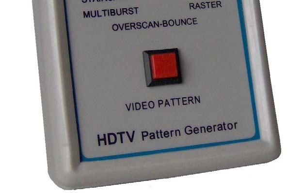
4 Understanding the Front Panel 1. Power ON/OFF switch This Power ON/OFF switch is on the left side of the unit. Slide the switch upward to turn the unit on and downward to turn the unit off. 2. Power ON/OFF LED Power is ON when the LED lights up and power is off when the LED is off Battery Low LED When the HG139 is operating on a 9V battery and the voltage on the battery is drop down to around 5V, this green LED will turn on indicating the voltage on the battery is low V DC adaptor input Connect the 7.5V 200mA center positive AC adaptor (included) to power the HG Video Format selector Use this selector to choose one of the following video formats: i p p NTSC (only luminance signal output for NTSC) 6. Video Pattern button Use this button to cycle through one of the following video patterns: COLOR BARS CROSS HATCH STAIRCASE MULTIBURST OVERSCAN-BOUNCE PLUGE NEEDLE CHECKER RASTER NOTE: Holding down this button will display previous patterns in reverse order until COLOR BARS pattern is reached. 7. YPbPr Video Connectors These three BNC connectors are labeled Y, Pb, and Pr. With 1080i, 720p, or 480p mode on the HG139 selected, using BNC cables, connect the three BNC connectors to the TV s respective Y, Pb, and Pr component video connectors to output the video signal to the TV. For TVs that use RCA connectors for component video inputs, use the included BNC-to-RCA adaptors to connect HG139 to the TV. With the NTSC mode selected, the video signal will come from the Y connector on the HG139. Connect the Y output to the TV s composite video input with a BNC or RCA cable. 2
5 Basic Operation 1. a: Connect the Y, Pb, and Pr connectors on the HG139 to the HDTV Y, Pb, and Pr component video inputs respectively. The Y is the luminance signal, and Pb and Pr are the chrominance (color) signals. The Y signal will drive a 1V peak-to-peak signal into a 75-ohm load, and the Pb and Pr signals will drive 0.7V peak-to-peak signals into 75-ohm loads. b: In the case of testing NTSC TV, connect the Y connector on HG139 to the composite video input on the TV. This connection provides no chrominance, so Color Bars and Raster will display only luminance with no color. The other patterns will display normally. 2. Using the video format selector, select the appropriate video format on the HG139. Available video formats include 1080i, 720p, 480p, and NTSC. 3. Slide the power switch to turn on HG Use the video pattern button to select the desire video pattern for display. Available video patterns include COLOR BARS, CROSS HATCH, STAIRCASE, MULTIBURST, OVERSCAN-BOUNCE, PLUGE, NEEDLE, CHECKER, and RASTER (White, Yellow, Cyan, Green, Magenta, Red, Blue, and Black). NOTE: Holding down the video pattern button will display previous patterns in reverse order until COLOR BARS pattern is reached 3
6 4


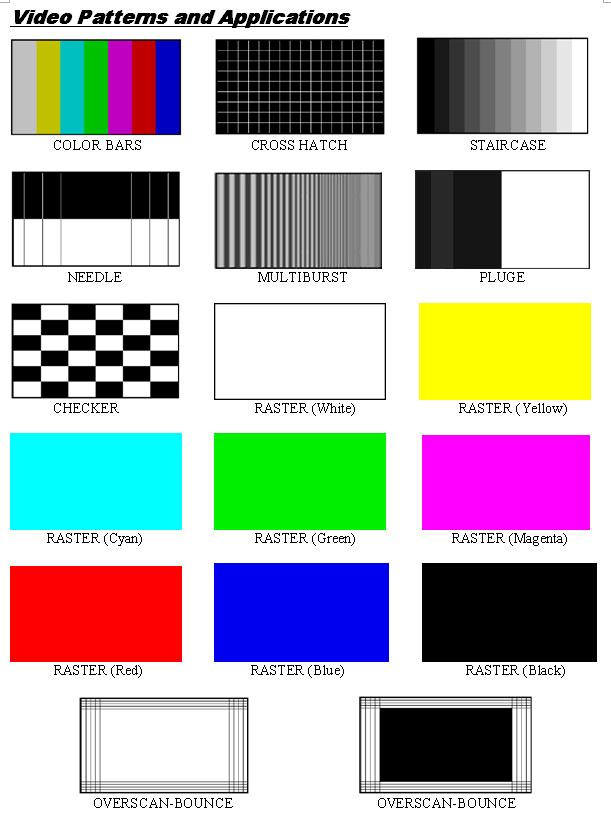
7 COLOR BARS Seven equal width vertical color bars are displayed at 75% amplitude, 100% saturation in the order from left to right: White, Yellow, Cyan, Green, Magenta, Red, and Blue. The COLOR BARS video pattern serves as the fundamental pattern used for most testing, troubleshooting and adjustments in video equipment. Use this test pattern to check and test the video device s ability to produce fully saturated primary and secondary colors. It is often used as the reference for color adjustment and compensation. When troubleshooting, analysis of the colors bars pattern helps television service personnel to pinpoint color related problem to specific circuits. This pattern can also be use as a reference for troubleshooting color amplifier or color demodulator problems inside the display device. CROSS HATCH This pattern displays a series of horizontal and vertical straight white lines that forms a grid of 16 x 9 squares of the same size for 1080i and 720p, 12 x 9 squares for 480p and NTSC. This pattern used to check and adjust dynamic convergence of the display. Observe the horizontal and vertical lines to detect color fringing resulting from misconvergence. An example that the display is misconverged is when the white lines become separated Red, Green, and Blue lines. Adjust the display s RGB convergence control to align the colors to overlap so the horizontal and vertical lines appear as white lines. This pattern can also be provides a convenience reference for making vertical and horizontal linearity adjustments. Each square should be the same size. CROSS HATCH pattern is also useful for checking pincushion (bow) distortion and display geometry such as picture centering, size, and trapezoid (keystone) correction. For trapezoid correction, adjust the TV s display control so that the pattern s edges are parallel to the edges of the display screen. For pincushion correction, the horizontal and vertical lines should be adjusted to be straight. 5


8 STAIRCASE The STAIRCASE pattern displays equal-width vertical bar steps of increasing luminance from left to right. This pattern is useful in checking amplifier linearity. The increment of amplitude from one step to the next should be equal. Non-equal steps represent non-linear distortion. Typical luminance nonlinear distortions will result in a loss of grey-scale distinctions, which means that detail is loss. Each of the vertical bars should have distinctive brightness level. The display is too dark when the black vertical bars blend together. The display is too bright when the white vertical bars blend together. Adjust the display cutoff/bias controls and drive/gain controls so each vertical bar has distinctive brightness level. This pattern is also useful for checking and adjusting the grayscale performance of a video device. This pattern is seen as a primary color (red, green, or blue) tint on display device with poor grayscale performance. MULTIBURST The MULTIBURST pattern displays five frequency bands of progressively higher frequency from left to right. The following frequencies are displayed: 1.16MHz, 2.32MHz, 4.64MHz, 9.28MHz, and 18.56MHz for 1080i / 720p formats; 0.58MHz, 1.16MHz, 2.32MHz, 4.64MHz, and 9.28MHz for 480p; 0.29MHz, 0.58MHz, 1.16MHz, 2.32MHz, 4.64MHz for NTSC format. This pattern is useful for measuring video equipment s resolution and video bandwidth. Each band consists of a series of alternating black and white vertical lines. The lines become closer as bands of higher frequency are displayed. The resolution of the equipment being tested can be determined by the maximum frequency at which individual lines can be discerned. Use this pattern to check a display device s capability to produce sharply defined alternating black and white stripes up to the format s full resolution. Depending on a device s ability to handle high frequency signals, some display devices with insufficient high frequency response will display this pattern with black and white stripes blurred together for the higher frequency bands. 6

9 OVERSCAN-BOUNCE. The Overscan-Bounce pattern consists of 4 horizontal lines on the top and bottom edge of the screen and 4 vertical lines at the left and right edge of the screen. These lines mark 2.5%, 5%, 7.5%, and 10% of the width and height of the screen. The background of the screen alternates between black and white. This pattern is useful for checking the amount of overscan of a display monitor. The 4 lines at each of the four edges are helpful in determining whether there is equal amount of overscan at the sides or at the top and bottom of the screen. Adjust the display device s geometry controls to obtain the desire amount of overscan or underscan. The Overscan-Bounce pattern is also useful for checking pincushion (bow) distortion and display geometry such as picture centering, size, and trapezoid (keystone) correction and linearity. For trapezoid correction, adjust the TV s display control so that the pattern s edges are parallel to the edges of the display screen. For pincushion correction, the horizontal and vertical lines should be adjusted to be straight. It is also used to check the stability of the high-voltage and deflection power supply circuits. The Overscan Bounce pattern changes repeatedly from a low to high APL (average picture level). As the picture APL changes, the picture size may momentarily expand and contract. The amount of change can be measured by the shift of the lines on the screen edges. 7
.")
10 PLUGE / The PLUGE (stands for Picture Line-Up Generation Equipment) pattern is divided into two halves. The left half consists of 2 vertical stripes against a black background, i.e. 7.5 IRE for NTSC and 0 IRE for the other patterns. The left stripe is fixed at a brightness level slightly whiter than black (12.5 IRE for NTSC and 5 IRE for the other video formats). The right stripe alternates between black and slightly blacker than black (7.5/2.5 IRE for NTSC, 0/-5 IRE for the other video formats). The right half of the pattern is fix at 57.5 IRE for NTSC and 50 IRE for the other formats. Note: the IRE values for NTSC is different from the other formats by 7.5 IRE due to the 7.5 IRE setup for the NTSC format. The PLUGE pattern is used to calibrate the black level on a display device. Black level basically refers to the brightness of the darkest areas in the picture. Adjust the appropriate controls on the display device (i.e. brightness and contrast controls, etc.) to calibrate the black level on the device. Refer to the following when making calibration: The left vertical stripe is just visible as a dark gray. The right vertical stripe alternates between black and slightly blacker so should not be visible against the background. If blinking can be seen on this vertical stripe, it means the brightness of the display is set too high. Lower the brightness level until the blinking barely disappears. The right half of the pattern is a lighter gray and should be clearly visible. This pattern is also useful for checking DC restoration (black clamping) performance of a display device. If a display device has good DC restoration, its black level control can be adjusted on either a low API (average picture level) or high APL pattern, with no change in black level as you switch from one pattern to another. Display device with less than perfect DC restoration will exhibit alternating changes of brightness in the black background and the +10 IRE vertical stripe. This is due to the display device s inability to perfectly clamp black to a fixed level. This can be determined when the brightness level is adjusted slightly above normal setting. If the brightness level of the two vertical stripes remains constant as the right stripe blinks (alternating between black and slightly blacker than black), the display has good DC restoration. 8

11 NEEDLE The NEEDLE pattern is symmetrically divided into top half and bottom half. The top half has black background with white vertical needle pulse lines and the bottom half has white background with black vertical needle pulse lines. The width of the vertical line should remain constant as it transitions between white and black. This pattern is useful for detecting whether scan velocity modulation (SVM) is enabled on the display monitor. SVM tends to introduce horizontal nonlinearity in the image, causing the black lines on the bottom of the pattern to be thicker than the white lines on the top of the pattern. The NEEDLE pattern also works very well for adjusting the contrast control for maximum light level while minimizing raster distortion or blooming. Blooming results in light from very bright pixels spilling over to adjacent pixels. This causes bright picture areas to become defocused and slightly larger than they should be. Raster distortion at high luminance level is caused by high voltage power supply regulation problems. The vertical needle pulses should be straight without any bowing. If the contrast is set too high, the display s power supply may cause raster distortion, visible as bending in the needle pulses. For the least picture distortion, adjust the contrast to a setting just below where either blooming or raster distortion becomes visible. This may sometimes result in a picture with unacceptably low white level. In this case, a compromise needed to be made between an accurate display and a brighter display. 9

12 CHECKER The CHECKER pattern displays alternating black and white boxes as in a checker board. This pattern is useful in checking the high voltage regulation of CRT power supply circuits. Poor regulation results in trapezoidal looking pattern. For CRT type monitors with insufficient power supply regulation can result in the corners of each box do not touch each other as they should. This effect can sometimes be reduced by lowering the brightness or contrast settings. This pattern is also useful for checking ringing of the video signal as the signal transitions from black to white. The abrupt, maximum change in CRT video drive current produced by this pattern should not cause the voltage supplied to the video drive circuit to change in display device with good voltage regulation. For display device with power supply that does not have good regulation, softening or ringing in the pattern transitions can result. RASTER The RASTER patterns consist of 8 full field color patterns at 75% amplitude. The colors displayed are: White, Yellow, Cyan, Green, Magenta, Red, Blue, and Black. RASTER patterns are useful for checking color purity and uniformity. Color purity problems are often caused by the magnetization of some parts inside a CRT display device. This often results in areas of color on the white raster pattern. Use the three primary color raster patterns (Red, Green, and Blue) to check for missing and defective pixels on a LCD monitor. Missing and defective pixels are common problems on this type of display devices. The Red, Green, and Blue raster patterns are valuable for adjusting the three separate guns that generate these three primary colors inside a display monitor. A full field display of each of the eight individual color RASTER patterns also simplifies the analysis of hue and saturation problems. 10
13 Specifications Video Modes Video Patterns Y output Pb output Pr output Clock Frequency Power Size (L x W x H) Weight 1920 x i 1280 x p 720 x p NTSC (luminance only) COLOR BARS CROSS HATCH STAIRCASE MULTIBURST OVERSCAN-BOUNCE PLUGE NEEDLE CHECKER RASTER Output impedance: 75Ω 1 Vp-p into 75Ω Output impedance: 75Ω 0.7 Vp-p into 75Ω Output impedance: 75Ω 0.7 Vp-p into 75Ω MHz 7.5V center-positive AC adaptor or 9V battery 5.7" x 3.3" x 1.5" (w/o rubber boot) 0.8 lb Specifications subject to change without notice. 11
14 Notes 12
GME. User s Manual. Rev 1.3
 GME User s Manual Rev 1.3 TEST INSTRUMENT SAFETY GUIDELINES WARNING An electrical shock of over 10 milliamps of current to pass through the heart will stop most human heartbeats. Voltage as low as 35 volts
GME. User s Manual. Rev 1.3
 GME User s Manual Rev 1.3 TEST INSTRUMENT SAFETY GUIDELINES WARNING An electrical shock of over 10 milliamps of current to pass through the heart will stop most human heartbeats. Voltage as low as 35 volts
Using the VP300 to Adjust Video Display User Controls
 Using the VP300 to Adjust Video Display User Controls Today's technology has produced extraordinary improvements in video picture quality, making it possible to have Cinema-like quality video right in
You Can Make Better Profits In Computer Monitor Servicing!
 You Can Make Better Profits In Computer Monitor Servicing! There s definitely more to servicing computer monitors than simply checking a couple of test points and changing parts. When you ve committed
SM02. High Definition Video Encoder and Pattern Generator. User Manual
 SM02 High Definition Video Encoder and Pattern Generator User Manual Revision 0.2 20 th May 2016 1 Contents Contents... 2 Tables... 2 Figures... 3 1. Introduction... 4 2. acvi Overview... 6 3. Connecting
TSG 90 PATHFINDER NTSC Signal Generator
 Service Manual TSG 90 PATHFINDER NTSC Signal Generator 070-8706-01 Warning The servicing instructions are for use by qualified personnel only. To avoid personal injury, do not perform any servicing unless
Patterns Manual September 16, Main Menu Basic Settings Misc. Patterns Definitions
 Patterns Manual September, 0 - Main Menu Basic Settings Misc. Patterns Definitions Chapters MAIN MENU episodes through, and they used an earlier AVS HD 0 version for the demonstrations. While some items,
Learning to Use The VG91 Universal Video Generator
 Learning to Use The VG91 Universal Video Generator Todays TV-video systems can be divided into 3 sections: 1) Tuner/IF, 2) Video and 3) Audio. The VG91 provides signals to fully test and isolate defects
Chapter 1 Introduction Package Contents Resolution Features Specifications Front Panel Side Panel...
 0 Chapter 1 Introduction...2 1.1 Package Contents...2 1.2 Resolution...3 1.3 Features...3 1.4 Specifications...3 1.5 Front Panel...4 1.6 Side Panel...5 1.6.1 RCA connectors...5 1.6.2 Power Jack...5 Chapter
SM01. Standard Definition Video Encoder. Pattern Generator. User Manual. and
 SM01 Standard Definition Video Encoder and Pattern Generator User Manual Revision 0.5 27 th February 2015 1 Contents Contents... 2 Tables... 3 Figures... 3 1. Introduction... 5 2. Connecting up the SM01...
Dan Schuster Arusha Technical College March 4, 2010
 Television Theory Of Operation Dan Schuster Arusha Technical College March 4, 2010 My TV Background 34 years in Automation and Image Electronics MS in Electrical and Computer Engineering Designed Television
High-Definition, Standard-Definition Compatible Color Bar Signal
 Page 1 of 16 pages. January 21, 2002 PROPOSED RP 219 SMPTE RECOMMENDED PRACTICE For Television High-Definition, Standard-Definition Compatible Color Bar Signal 1. Scope This document specifies a color
Presented by: Amany Mohamed Yara Naguib May Mohamed Sara Mahmoud Maha Ali. Supervised by: Dr.Mohamed Abd El Ghany
 Presented by: Amany Mohamed Yara Naguib May Mohamed Sara Mahmoud Maha Ali Supervised by: Dr.Mohamed Abd El Ghany Analogue Terrestrial TV. No satellite Transmission Digital Satellite TV. Uses satellite
Essentials of the AV Industry Welcome Introduction How to Take This Course Quizzes, Section Tests, and Course Completion A Digital and Analog World
 Essentials of the AV Industry Welcome Introduction How to Take This Course Quizzes, s, and Course Completion A Digital and Analog World Audio Dynamics of Sound Audio Essentials Sound Waves Human Hearing
NAPIER. University School of Engineering. Advanced Communication Systems Module: SE Television Broadcast Signal.
 NAPIER. University School of Engineering Television Broadcast Signal. luminance colour channel channel distance sound signal By Klaus Jørgensen Napier No. 04007824 Teacher Ian Mackenzie Abstract Klaus
ANTENNAS, WAVE PROPAGATION &TV ENGG. Lecture : TV working
 ANTENNAS, WAVE PROPAGATION &TV ENGG Lecture : TV working Topics to be covered Television working How Television Works? A Simplified Viewpoint?? From Studio to Viewer Television content is developed in
ESI VLS-2000 Video Line Scaler
 ESI VLS-2000 Video Line Scaler Operating Manual Version 1.2 October 3, 2003 ESI VLS-2000 Video Line Scaler Operating Manual Page 1 TABLE OF CONTENTS 1. INTRODUCTION...4 2. INSTALLATION AND SETUP...5 2.1.Connections...5
Specifications. Reference Documentation. Performance Conditions
 The material in this section is organized into two main groupings: the specification tables and the supporting figures. The specification tables include: 1. PAL general and test signal specifications 2.
INSTALATION PROCEDURE
 INSTALLATION PROCEDURE Overview The most difficult part of an installation is in knowing where to start and the most important part is starting in the proper start. There are a few very important items
Multimedia Systems Video I (Basics of Analog and Digital Video) Mahdi Amiri April 2011 Sharif University of Technology
 Mahdi Amiri April 2011 Sharif University of Technology") Course Presentation Multimedia Systems Video I (Basics of Analog and Digital Video) Mahdi Amiri April 2011 Sharif University of Technology Video Visual Effect of Motion The visual effect of motion is due
Course Presentation Multimedia Systems Video I (Basics of Analog and Digital Video) Mahdi Amiri April 2011 Sharif University of Technology Video Visual Effect of Motion The visual effect of motion is due
COMPOSITE VIDEO LUMINANCE METER MODEL VLM-40 LUMINANCE MODEL VLM-40 NTSC TECHNICAL INSTRUCTION MANUAL
 COMPOSITE VIDEO METER MODEL VLM- COMPOSITE VIDEO METER MODEL VLM- NTSC TECHNICAL INSTRUCTION MANUAL VLM- NTSC TECHNICAL INSTRUCTION MANUAL INTRODUCTION EASY-TO-USE VIDEO LEVEL METER... SIMULTANEOUS DISPLAY...
BTV Tuesday 21 November 2006
 Test Review Test from last Thursday. Biggest sellers of converters are HD to composite. All of these monitors in the studio are composite.. Identify the only portion of the vertical blanking interval waveform
ELECTRICAL ADJUSTMENT INSTRUCTIONS
 ELECTRICAL ADJUSTMENT INSTRUCTIONS General Note: "CBA" is abbreviation for "Circuit Board Assembly." NOTE: Electrical adjustments are required after replacing circuit components and certain mechanical
Broadcast and Professional Monitors
 Broadcast and Professional Monitors NTSC area Sony's legendary line of broadcast monitors now has a new family of additions. The BVM-D series digital monitors are optimized for the DTV world. They support
CM-1UTP CAMERA MASTER UTP ADAPTOR
 CM-1UTP CAMERA MASTER UTP ADAPTOR INSTRUCTION BOOK CM-1UTP.ISB TABLE OF CONTENTS FORWARD 2 VIDEO STANDARDS 2 COAXIAL CABLE vs UTP WIRE CABLE 3 MEASUREMENT 3 MOUNTING THE CM1-UTP ADAPTOR 3 UTP WIRE CABLE
Broadcast and Professional Monitors
 Broadcast and Professional Monitors NTSC area Sony's legendary line of broadcast monitors now has a new family of additions. The BVM-D series digital monitors are optimized for the DTV world. They support
RECOMMENDATION ITU-R BT (Question ITU-R 211/11)
") Rec. ITU-R T.814-1 1 RECOMMENDATION ITU-R T.814-1 SPECIICATIONS AND ALIGNMENT PROCEDURES OR SETTING O RIGTNESS AND CONTRAST O DISPLAYS (Question ITU-R 211/11) Rec. ITU-R T.814-1 (1992-1994) The ITU Radiocommunication
Rec. ITU-R T.814-1 1 RECOMMENDATION ITU-R T.814-1 SPECIICATIONS AND ALIGNMENT PROCEDURES OR SETTING O RIGTNESS AND CONTRAST O DISPLAYS (Question ITU-R 211/11) Rec. ITU-R T.814-1 (1992-1994) The ITU Radiocommunication
Advanced Test Equipment Rentals ATEC (2832)
") Established 1981 Advanced Test Equipment Rentals www.atecorp.com 800-404-ATEC (2832) SECTION 1 : Introduction The TSG 120 YC/NTSC Signal Generator is a simple, cost-effective test signal generator designed
Established 1981 Advanced Test Equipment Rentals www.atecorp.com 800-404-ATEC (2832) SECTION 1 : Introduction The TSG 120 YC/NTSC Signal Generator is a simple, cost-effective test signal generator designed
Traditionally video signals have been transmitted along cables in the form of lower energy electrical impulses. As new technologies emerge we are
 2 Traditionally video signals have been transmitted along cables in the form of lower energy electrical impulses. As new technologies emerge we are seeing the development of new connection methods within
S op o e p C on o t n rol o s L arni n n i g n g O bj b e j ctiv i e v s
 ET 150 Scope Controls Learning Objectives In this lesson you will: learn the location and function of oscilloscope controls. see block diagrams of analog and digital oscilloscopes. see how different input
HIGH DEFINITION MONITOR HDM 5049 PLUS USER S MANUAL
 BARCO N.V. Communication Systems Th. Sevenslaan 106 B-8500 Kortrijk (Belgium) Tel.: +32.56.233.211 Fax: + 32.56.233.461 E-mail: support.bcs@barco.com Web site: http://www.barco.com HIGH DEFINITION MONITOR
1995 METRIC CSJ SPECIAL SPECIFICATION ITEM 6573 CCTV CENTRAL EQUIPMENT
 1995 METRIC CSJ 0196-03-209 SPECIAL SPECIFICATION ITEM 6573 CCTV CENTRAL EQUIPMENT 1.0 DESCRIPTION. THIS ITEM SHALL GOVERN FOR THE FURNISHING AND INSTALLATION OF CLOSED CIRCUIT TELEVISION (CCTV) CENTRAL
Software Analog Video Inputs
 Software FG-38-II has signed drivers for 32-bit and 64-bit Microsoft Windows. The standard interfaces such as Microsoft Video for Windows / WDM and Twain are supported to use third party video software.
Waveform Monitor/Vectorscope, PM 5661 Waveform Monitor/Vectorscope, Sc-H, PM 5661/70
 Waveform Monitor/Vectorscope, PM 5661 Waveform Monitor/Vectorscope, Sc-H, PM 5661/70 Two instruments combined in one unit PM 5661/70 features Sc-H phase display Input Signal Subtraction (A-B) for easy
DEPARTMENT OF THE ARMY TECHNICAL BULLETIN CALIBRATION PROCEDURE FOR AUTOMATIC VIDEO CORRECTOR TEKTRONIX, MODEL 1440 (NSN )
") DEPARTMENT OF THE ARMY TECHNICAL BULLETIN TB 11-5820-861-35 CALIBRATION PROCEDURE FOR AUTOMATIC VIDEO CORRECTOR TEKTRONIX, MODEL 1440 (NSN 5820-00-570-1978) Headquarters, Department of the Army, Washington,
DEPARTMENT OF THE ARMY TECHNICAL BULLETIN TB 11-5820-861-35 CALIBRATION PROCEDURE FOR AUTOMATIC VIDEO CORRECTOR TEKTRONIX, MODEL 1440 (NSN 5820-00-570-1978) Headquarters, Department of the Army, Washington,
VectorVGA Tempest User Manual
 VectorVGA Tempest User Manual 2 Notice Regarding This Product WARNING! To install this product you should: Be familiar with safe handling procedures for electronic components. Be able to use hand tools
Elegance Series Components / New High-End Audio Video Products from Esoteric
 Elegance Series Components / New High-End Audio Video Products from Esoteric Simple but elegant 3 inch height achieved in a new and original chassis Aluminum front panel. Aluminum and metal casing. Both
Color Video Monitors WV-CK1420/2020 WV-CM1000/1430/1470. B/W Video Monitors WV-BM500/503/900/1410/1700/1910
 R Color Video Monitors WV-CK420/2020 WV-CM000/430/470 B/W Video Monitors WV-BM500/503/900/40/700/90 Panasonic video monitors can be used not just in CCTV systems but in a wide range of applications such
PRODUCT NO.: PT-L735NT PRODUCT NAME: Ultra Portable Wireless LCD Projector
 PRODUCT NO.: PRODUCT NAME: Ultra Portable Wireless LCD Projector MAJOR FEATURES Bright - High 2600 ANSI lumens brightness Easy wireless presentations - Easy-to-use settings - Useful Live mode - PC-free
Video to PC/HD Scaler Box. Operation Manual
 Video to PC/HD Scaler Box Operation Manual (1). Introduction Congratulations on your purchase of the Cypress Video Scaler CM-390. Our professional Video Scaler products have been serving the industry for
PRODUCT NO.: PT-L735 PRODUCT NAME: Ultra Portable LCD Projector
 PRODUCT NO.: PRODUCT NAME: MAJOR FEATURES Bright - High 2600 ANSI lumens brightness Time-saving - One-touch auto setup - Automatic input signal detector - Speed start - Direct power off - Momentary switch
User Manual. PC / HD Scaler. with advanced video processing. VGA to Component Video Component Video to VGA VGA to VGA Component to Component
 User Manual PC / HD Scaler with advanced video processing VGA to Component Video Component Video to VGA VGA to VGA Component to Component Model 1366 WARNINGS Read these instructions before installing or
What is sync? Why is sync important? How can sync signals be compromised within an A/V system?... 3
 Table of Contents What is sync?... 2 Why is sync important?... 2 How can sync signals be compromised within an A/V system?... 3 What is ADSP?... 3 What does ADSP technology do for sync signals?... 4 Which
Interfaces and Sync Processors
 Interfaces and Sync Processors Kramer Electronics has a full line of video, audio and sync interfaces. The group is divided into two sections Format Interfaces and Video Sync Processors. The Format Interface
Avia PRO Video Test DVD
 Avia PRO Video Test DVD Guy Kuo, Ovation Multimedia, Inc. Introduction This chapter discusses the video test signals found on the Avia PRO Video Test DVD and its supplemental 4:3 Ratio DVD. Avia PRO contains
USER MANUAL. VP-435 Component / UXGA HDMI Scaler MODEL: P/N: Rev 13
 KRAMER ELECTRONICS LTD. USER MANUAL MODEL: VP-435 Component / UXGA HDMI Scaler P/N: 2900-000262 Rev 13 Contents 1 Introduction 1 2 Getting Started 2 2.1 Achieving the Best Performance 2 2.2 Safety Instructions
IBM Enhanced Color Display. Personal Computer. Hardware Reference Library _.-
 ---- - - ---- ----- - --- Personal Computer --_.- Hardware Reference Library IBM Enhanced Color Display Contents Description... 1 Operating Characteristics... 2 Specifications... 5 Connector Information...
Finally an affordable video mixer for the foundation of. your multi-format video production.
 Pick Hit Award From Broadcast Engineering Magazine at NAB 2005 Mix Multiple Input Formats Capable of mixing HD (1080i/720p:component), (S-Video, Composite) or from computer (from VGA to SXGA). Choose from
WVR500 Waveform/Vector Monitor
 Service Manual WVR500 Waveform/Vector Monitor 070-8897-01 Warning The servicing instructions are for use by qualified personnel only. To avoid personal injury, do not perform any servicing unless you are
VGA Port. Chapter 5. Pin 5 Pin 10. Pin 1. Pin 6. Pin 11. Pin 15. DB15 VGA Connector (front view) DB15 Connector. Red (R12) Green (T12) Blue (R11)
 DB15 Connector. Red (R12) Green (T12) Blue (R11)") Chapter 5 VGA Port The Spartan-3 Starter Kit board includes a VGA display port and DB15 connector, indicated as 5 in Figure 1-2. Connect this port directly to most PC monitors or flat-panel LCD displays
Chapter 5 VGA Port The Spartan-3 Starter Kit board includes a VGA display port and DB15 connector, indicated as 5 in Figure 1-2. Connect this port directly to most PC monitors or flat-panel LCD displays
RICHLAND COLLEGE School of Engineering Business & Technology Rev. 0 W. Slonecker Rev. 1 (8/26/2012) J. Bradbury
 J. Bradbury") RICHLAND COLLEGE School of Engineering Business & Technology Rev. 0 W. Slonecker Rev. 1 (8/26/2012) J. Bradbury INTC 1307 Instrumentation Test Equipment Teaching Unit 8 Oscilloscopes Unit 8: Oscilloscopes
RICHLAND COLLEGE School of Engineering Business & Technology Rev. 0 W. Slonecker Rev. 1 (8/26/2012) J. Bradbury INTC 1307 Instrumentation Test Equipment Teaching Unit 8 Oscilloscopes Unit 8: Oscilloscopes
OPERATING GUIDE. HIGHlite 660 series. High Brightness Digital Video Projector 16:9 widescreen display. Rev A June A
 OPERATING GUIDE HIGHlite 660 series High Brightness Digital Video Projector 16:9 widescreen display 111-9714A Digital Projection HIGHlite 660 series CONTENTS Operating Guide CONTENTS About this Guide...
4.9 BEAM BLANKING AND PULSING OPTIONS
 4.9 BEAM BLANKING AND PULSING OPTIONS Beam Blanker BNC DESCRIPTION OF BLANKER CONTROLS Beam Blanker assembly Electron Gun Controls Blanker BNC: An input BNC on one of the 1⅓ CF flanges on the Flange Multiplexer
OSCILLOSCOPE AND DIGITAL MULTIMETER
 Exp. No #0 OSCILLOSCOPE AND DIGITAL MULTIMETER Date: OBJECTIVE The purpose of the experiment is to understand the operation of cathode ray oscilloscope (CRO) and to become familiar with its usage. Also
To discuss. Types of video signals Analog Video Digital Video. Multimedia Computing (CSIT 410) 2
 2") Video Lecture-5 To discuss Types of video signals Analog Video Digital Video (CSIT 410) 2 Types of Video Signals Video Signals can be classified as 1. Composite Video 2. S-Video 3. Component Video (CSIT
Video Lecture-5 To discuss Types of video signals Analog Video Digital Video (CSIT 410) 2 Types of Video Signals Video Signals can be classified as 1. Composite Video 2. S-Video 3. Component Video (CSIT
ModelV-LCD70-AFHD. Operating Instructions
 ModelV-LCD70-AFHD Operating Instructions 1 2 This page intentionally left blank Table of Contents Top and Front Panel Features...6 Rear Panel Features...7 Compatible Input Formats...8 MAIN MENU AND NAVIGATION...9
700 Series. Portable Video Test Generators. Quick Start Guide
 700 Series Portable Video Test Generators Quick Start Guide Contents Model 700, 701 Video Test Generators Quick Start Guide Getting Started... 2 Computer Interfaces... 3 User Interface... 4 Selecting Formats...
Chapter 3 Fundamental Concepts in Video. 3.1 Types of Video Signals 3.2 Analog Video 3.3 Digital Video
 Chapter 3 Fundamental Concepts in Video 3.1 Types of Video Signals 3.2 Analog Video 3.3 Digital Video 1 3.1 TYPES OF VIDEO SIGNALS 2 Types of Video Signals Video standards for managing analog output: A.
Analog Dual-Standard Waveform Monitor
 Test Equipment Depot - 800.517.8431-99 Washington Street Melrose, MA 02176 - TestEquipmentDepot.com Analog Dual-Standard Waveform Monitor 1741C Datasheet Additional Analysis Features Timing Display for
INTRODUCTION TO THE APPLE" SYSTEM
 O/458 INTRODUCTION TO THE APPLE" SYSTEM An understanding of the "Apple" system of color television reception is greatly aided by the following ultra simplified review of the color television signal properties.
Television History. Date / Place E. Nemer - 1
 Television History Television to see from a distance Earlier Selenium photosensitive cells were used for converting light from pictures into electrical signals Real breakthrough invention of CRT AT&T Bell
FITTING AN EGA CARD TO AN IBM 5155.
 FITTING AN EGA CARD TO AN IBM 5155. H. Holden 2016. Updated 12 March. 2016. In graphics mode the CGA card has a limited color palette. This consists of two palette systems: One Background color plus Red,
Setting Up the Warp System File: Warp Theater Set-up.doc 25 MAY 04
 Setting Up the Warp System File: Warp Theater Set-up.doc 25 MAY 04 Initial Assumptions: Theater geometry has been calculated and the screens have been marked with fiducial points that represent the limits
Model 5240 Digital to Analog Key Converter Data Pack
 Model 5240 Digital to Analog Key Converter Data Pack E NSEMBLE D E S I G N S Revision 2.1 SW v2.0 This data pack provides detailed installation, configuration and operation information for the 5240 Digital
Model 7405 High Definition Test Signal Generator Data Pack
 Model 7405 High Definition Test Signal Generator Data Pack E NSEMBLE D E S I G N S Revision 1.1 SW v1.1.0 This data pack provides detailed installation, configuration and operation information for the
User Manual VM700T Video Measurement Set Option 30 Component Measurements
 User Manual VM700T Video Measurement Set Option 30 Component Measurements 070-9654-01 Test Equipment Depot - 800.517.8431-99 Washington Street Melrose, MA 02176 - FAX 781.665.0780 - TestEquipmentDepot.com
KD-VP800 RGBHV-to-Component Digital Video Scaler & Video Adapter
 KD-VP800 RGBHV-to-Component Digital Video Scaler & Video Adapter Operating Instructions The KD-VP800 by Key Digital is a universal analog Video Scaler and Adapter that converts RGBHV Video sources to Component
Thank you for your interest in BARCO s dedicated Home Theater products and more particular in our top-model, the CINE9.
 D e a r H o m e T h e a t e r E n t h u s i a s t, Thank you for your interest in BARCO s dedicated Home Theater products and more particular in our top-model, the CINE9. Just like you, we always strive
PT-LB382 S P E C F I L E. LCD Projectors. As of July Specifications and appearance are subject to change without notice. 1/9.
 S P E C F I L E Product Number : Product Name : LCD Projectors As of July 2015. Specifications and appearance are subject to change without notice. 19 Specifications Main unit Power supply Power consumption
CYPRESS TECHNOLOGY CO., LTD.
 (1). Introduction Congratulations on your purchase of the Cypress Video Scaler CSC-200P. Our professional Video Scaler products have been serving the industry for many years. In addition to Video Scalers,
Computer Graphics. Raster Scan Display System, Rasterization, Refresh Rate, Video Basics and Scan Conversion
 Computer Graphics Raster Scan Display System, Rasterization, Refresh Rate, Video Basics and Scan Conversion 2 Refresh and Raster Scan Display System Used in Television Screens. Refresh CRT is point plotting
VIDEO 101 LCD MONITOR OVERVIEW
 VIDEO 101 LCD MONITOR OVERVIEW This provides an overview of the monitor nomenclature and specifications as they relate to TRU-Vu industrial monitors. This is an ever changing industry and as such all specifications
Elements of a Television System
 1 Elements of a Television System 1 Elements of a Television System The fundamental aim of a television system is to extend the sense of sight beyond its natural limits, along with the sound associated
Mahdi Amiri. April Sharif University of Technology
 Course Presentation Multimedia Systems Video I (Basics of Analog and Digital Video) Mahdi Amiri April 2014 Sharif University of Technology Video Visual Effect of Motion The visual effect of motion is due
iii Table of Contents
 i iii Table of Contents Display Setup Tutorial....................... 1 Launching Catalyst Control Center 1 The Catalyst Control Center Wizard 2 Enabling a second display 3 Enabling A Standard TV 7 Setting
DVM-3000 Series 12 Bit DIGITAL VIDEO, AUDIO and 8 CHANNEL BI-DIRECTIONAL DATA FIBER OPTIC MULTIPLEXER for SURVEILLANCE and TRANSPORTATION
 DVM-3000 Series 12 Bit DIGITAL VIDEO, AUDIO and 8 CHANNEL BI-DIRECTIONAL FIBER OPTIC MULTIPLEXER for SURVEILLANCE and TRANSPORTATION Exceeds RS-250C Short-haul and Broadcast Video specifications. 12 Bit
BVM-A Series. New horizons for broadcast monitors. Broadcast and Professional Monitors.
 New horizons for broadcast monitors. BVM-A Series Broadcast and Professional Monitors for Evaluation, Critical and Reference Monitoring www.sonybiz.net/media The BVM-A Series of digital monitors the widest
KRAMER ELECTRONICS LTD. USER GUIDE MODEL: VP-790 Blending Projected Images on a Curved Screen. P/N: Rev 1
 KRAMER ELECTRONICS LTD. USER GUIDE MODEL: VP-790 Blending Projected Images on a Curved Screen P/N: 2900-300214 Rev 1 Contents 1 Introduction 1 2 Setting the Basic System 2 2.1 Optical Alignment 3 3 Setting
AVIA Professional A multi-disc calibration, set-up and test suite Developed by: Ovation Multimedia, Inc. July, 2003
 AVIA Professional A multi-disc calibration, set-up and test suite Developed by: Ovation Multimedia, Inc. July, 2003 AVIA Professional General Information What is AVIA Professional? AVIA Professional (AVIA
KD-CSW2x1. Operating Instructions. 2 Inputs to 1 Output Component Video/Audio Switcher. KD-CSW2x1 Operating Instructions.
 KD-CSW2x1 2 Inputs to 1 Output Video/ Switcher Operating Instructions Key Digital, led by digital video pioneer Mike Tsinberg, develops and manufactures high quality, cutting-edge technology solutions
BVM-D Series. Multiformat Monitors. Unquestioned performance. Uncompromising quality. this is not a rehearsal.
 BVM-D Series Multiformat Monitors Unquestioned performance. Uncompromising quality. this is not a rehearsal. www.pro.sony-europe.com 1 Defining Multiformat Quality SONY'S LEGENDARY LINE OF BROADCAST MONITORS
Component Video Matrix Switcher Series ITEM NO.: YS04MA, YS04MD
 Component Video Matrix Switcher Series ITEM NO.: YS04MA, YS04MD Our component video switcher allows four different component video and stereo/digital audio sources to share two video displays. Manage multiple
Product Number : LW373 Product Name : As of October Specifications and appearance are subject to change without notice.
 S P E C F I L E Product Number : Product Name : LCD Projectors As of October 2016. Specifications and appearance are subject to change without notice. 19 Specifications Main unit Power supply Power consumption
Ch. 1: Audio/Image/Video Fundamentals Multimedia Systems. School of Electrical Engineering and Computer Science Oregon State University
 Ch. 1: Audio/Image/Video Fundamentals Multimedia Systems Prof. Ben Lee School of Electrical Engineering and Computer Science Oregon State University Outline Computer Representation of Audio Quantization
Crystal Sanchez Video Preservation 1 December Video Preservation Project: No Setup vs. Setup
 Crystal Sanchez Video Preservation 1 December 2011 Video Preservation Project: No Setup vs. Setup When doing transfers of analog video materials, there are a variety of choices available to the preservation
Despite the now standard digital distribution of video signals, analog video signals are still an integral part of AV terminals in the home.
 Application Note Harald Ibl 5.2015 7MH107_0E Testing of Analog Video Component Signals Application Note Products: R&S VTC R&S VTE R&S VTS R&S BTC Despite the now standard digital distribution of video
Video to DVI 1080p Scaler Box - ID# 796
 Video to DVI 1080p Scaler Box - ID# 796 Operation Manual Introduction Video to DVI 1080p Scaler Box is an upgraded design to convert Standard Definition Composite Video (CV) and S-Video (SV) signals to
PT-LB385 S P E C F I L E. LCD Projectors. As of December Specifications and appearance are subject to change without notice.
 S P E C F I L E Product Number : Product Name : LCD Projectors. Specifications and appearance are subject to change without notice. 19 Specifications Main unit Power supply Power consumption AC100 240
Video Scaler Pro with RS-232
 Video Scaler Pro with RS-232 - ID# 783 Operation Manual Introduction Features The Video Scaler Pro with RS-232 is designed to convert Composite S-Video and YCbCr signals to a variety of computer and HDTV
Projection Series from JVC
 Projection Models Projection Series from JVC When you think of quality consumer electronics one name that invariably comes to mind is JVC. Having great products in all areas of consumer electronics, we
KRAMER ELECTRONICS LTD. USER GUIDE MODEL: VP-790 Blending Projected Images on a Flat Screen. P/N: Rev 1
 KRAMER ELECTRONICS LTD. USER GUIDE MODEL: VP-790 Blending Projected Images on a Flat Screen P/N: 2900-300215 Rev 1 Contents 1 Introduction 1 2 Setting the Basic System 2 2.1 Optical Alignment 3 3 Setting
Instruction Guide. Component/Composite/S-Video to DVI-D/HDTV Scaler and Converter Component/Composite/S-Video to VGA/HDTV Scaler and Converter
 VIDEO SCALER Component/Composite/S-Video to DVI-D/HDTV Scaler and Converter Component/Composite/S-Video to VGA/HDTV Scaler and Converter VID2DVIDTV (DVI) VID2VGATV (VGA) Instruction Guide * Actual product
CM-392-Video to HDMI Scaler Box ID#481
 CM-392-Video to HDMI Scaler Box ID#481 Operation Manual Introduction CM-392-Video to HDMI Scaler Box is designed to convert Composite and S-Video to Digital HDMI in a variety of HDTV resolutions. It handles
Installation Guide. CVC 300 Component Video and HDTV to RGB Converter Rev. B 12 08
 Installation Guide CVC 00 Component and HDTV to RGB Converter --0 Rev. B 0 V A MAX 0 0 0 0 0 LAN Introduction The Extron CVC 00 Component Converter converts all standard component video formats: NTSC/PAL,
Gateway 46-inch Plasma TV Specifications
 Gateway 46-inch Plasma TV Specifications Specifications are subject to change without notice or obligation. Display Panel Screen size Aspect ratio Number of pixels Pixel Pitch Luminance Diagonal 46-inch
HD Color LCD Monitor. 7" High Resolution On-Camera Field, Director Professional Monitor. User manual
 HD Color LCD Monitor 7" High Resolution On-Camera Field, Director Professional Monitor User manual Dear users: Thank you for purchasing our On-Camera Field HD Monitor Kit. This monitor employs professional
Gateway 50-inch Plasma TV Specifications
 Gateway 50-inch Plasma TV Specifications Specifications are subject to change without notice or obligation. Display Panel Screen size Aspect ratio Number of pixels Pixel Pitch Luminance Diagonal 50-inch
K Service Source. Macintosh Color Display
 K Service Source Macintosh Color Display K Service Source Specifications Macintosh Color Display Specifications Characteristics - 1 Characteristics Picture Tube 14-in. diagonal (11.5-in. viewable image)
KRAMER ELECTRONICS LTD. USER MANUAL
 KRAMER ELECTRONICS LTD. USER MANUAL MODEL: Projection Curved Screen Blend Guide How to blend projection images on a curved screen using the Warp Generator version K-1.4 Introduction The guide describes
Home Cinema Projector LPX-500
 LPX-5 NEW PRODUCT BULLETIN Home Cinema Projector LPX-5 LCD projector designed exclusively for home cinema use featuring 16:9 widescreen display capability, high contrast film-like picture quality, Yamaha