Implementation of a High-Speed Distribution Network Reconfiguration Scheme by Greg Hataway, Ted Warren, and Chris Stephens.
|
|
|
- Emmeline Bruce
- 6 years ago
- Views:
Transcription

1 The following technical papers supporting this presentation are available at Trip and Restore Distribution Circuits at Transmission Speeds by Jeff Roberts and Karl Zimmerman International Drive Distribution Automation and Protection by James R. Fairman, Karl Zimmerman, Jeff W. Gregory, and James K. Niemira Distribution Single-Phase Tripping and Reclosing: Overcoming Obstacles With Programmable Recloser Controls by Robert M. Cheney, John T. Thorne, and Greg Hataway. Implementation of a High-Speed Distribution Network Reconfiguration Scheme by Greg Hataway, Ted Warren, and Chris Stephens. 1
2 2

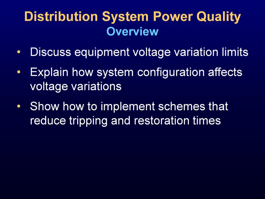
3 In this discussion of distribution power quality, we will: Review distribution service reliability measurements. Compare some common tripping and restoration schemes and show that faster is indeed better for most installations. 3
4 4

5 Distribution automation (DA) has been around for many years, and it simply means the automation of the distribution system. This automation may involve coordinating protection between two or more points on the system, automatic reconfiguration of the distribution system, or even something as simple as remote engineering access, control, and automatic collection of events. 5

6 In order to justify a DA system, a utility must have a reasonable return on investment. Generally, this return is most easily realized from improved reliability metrics. The primary goal of a DA system is to reduce customer outage times by maintaining high system reliability. There are several metrics used to track outages, including standard IEEE reliability indices. A DA system can reduce the opportunity for human error by performing the necessary decisions, verifications, and switching operations during a fault condition, a time when operations staff will be experiencing higher stress levels. By automating identification, isolation, and restoration operations in response to an outage, operations personnel can focus on other important tasks, such as dispatching crews to the known trouble spot to repair the faulted section. The crews will spend much less windshield time because they do not have to examine miles of distribution lines to find the faulted section. 6
 system that both fall under the distributed control type of DA system.")
7 There are several different philosophies when it comes to DA. They can generally be divided into two groups: centralized control, either at the substation or a control center, and distributed control. There are many variations of these two options, including the highspeed peer-to-peer system and the close-before-open (CBO) system that both fall under the distributed control type of DA system. Because different utilities have different requirements and other considerations on their systems, each utility will need to consider the benefits of each system type. A system that works well in a residential setting may not be the best choice for commercial loads. 7

8 With so many options in DA systems, utilities must consider a number of factors when choosing a system, including the following: Criticality of load. If a load cannot tolerate interruptions, then the best option may be a high-speed peer-to-peer system. Cost. Centralized control systems are generally more expensive because of the need for additional communications equipment, engineering services work, or other equipment. Distance between devices. Less distance between devices provides for better sectionalizing, results in fewer customers impacted by an interruption, but does add cost. Time to restore load. Reduced restoration time improves reliability indices but may require higher levels of automation or additional communications equipment. Type of switches applied. SEL equipment with MIRRORED BITS communications is well-suited for peer-to-peer applications. If equipment from other manufacturers is being used, it may be more practical to use a centralized control system that offers more flexibility in communications options. 8
9 9

10 The SEL Distribution Network Automation (DNA ) system is a perfect example of a centralized control DA system. The control may be located in a substation or placed in a central control center. Some utilities are using hybrid arrangements that have individual DA controllers in substations and a distributed DA system that incorporates into recloser controls in the event that communications are lost. 10
 in the supervisory control and data acquisition (SCADA) system.")
11 A DA control system collects data from many devices located throughout the distribution network. The DA controller can act as a remote terminal unit (RTU) in the supervisory control and data acquisition (SCADA) system. One extra node on the SCADA system can provide a wealth of information about multiple feeders to the distribution operations center. 11

12 Communications infrastructure is a major cost related to any automation system that services a wide geographic area. The application of automatic isolation and restoration is one of several wide-area applications that can provide value to the electric utility. Other applications include capacitor bank control, load balancing, volt/var optimization, demand management, and automatic meter reading. One of these applications alone may not provide enough benefit to the utility to justify the cost of the necessary communications infrastructure. However, by evaluating multiple applications including DA, the benefits become significant and outweigh the costs. 12

13 The distribution system has a wide range of applications for DA solutions. A simple application may include only three or four switching devices and two sources. However, there are situations that demand a more complex solution. Some applications will include four, five, or six sources and dozens of switching devices that must work together to minimize the impact of faults in the system. It is possible to design DA control systems that can be applied to simple as well as complex distribution networks. 13

14 There are constraints that must be respected by the DA control system. When the control system reconfigures the distribution network, loads are automatically picked up by adjacent feeders to return service to customers. The control system must avoid actions that result in overloading equipment or conductors. In larger systems, there are often multiple alternate feeds from which to choose. The control system must intelligently select the alternate feed that ensures the best operating margin. Modern distribution networks utilize pole-mounted reclosers to provide better selectivity in clearing faults. It is important to recognize that once the distribution network is reconfigured, the protection devices located throughout the network may not be coordinated in the new network configuration. The DA control system must attempt to preserve the coordination of protection devices, such as feeder breaker relays and recloser controls. Any automated system must hold the safety of personnel as a fundamental principle guiding its actions. Many line crew personnel may not be aware that a wide-area DA control system is in operation. Therefore, the DA control system must monitor typical indications of line crew activity, such as hot-line tag indication and nonreclose status from the recloser controls. Also, automatic actions at one switching device affect other areas in the distribution network. The DA control system must be selective to ensure the safety of personnel. 14

15 In order to meet the objectives of a DA control system, an accurate representation of the operating state of the distribution network is necessary. Fault current detectors allow the control system to determine which sections of the feeder are faulted. Fault detectors used in conjunction with lockout indications from upstream breakers and reclosers distinguish temporary faults from permanent faults. Voltage indications allow the control system to detect broken jumper conditions. Also, voltage indications provide verification that potential alternate feeds are energized and capable of picking up additional load. Load measurements allow the control system to calculate the amount of load that is deenergized and requires an alternate feed. Also, load measurements are needed to calculate the present available capacity for all potential alternate feeds. These data allow the control system to select the best alternate feed to re-energize customers. Abnormal condition indications, such as hot-line tags, nonreclose, diagnostic failures, and others, allow the control system to avoid undesirable actions. Status and control of switching devices allow the control system to reconfigure the distribution network. Status and control of settings groups allow the control system to preserve the coordination of protection devices after the distribution network is reconfigured. 15

16 The SEL DNA system responds to common failures on distribution networks and manages the situation in an intelligent manner to minimize customer outages. Permanent fault detection is based on fault current and lockout indications from switching devices on the feeder. The feeder is evaluated zone by zone, starting at the point farthest from the source. The fault current indications are used to identify the switching devices that have experienced fault current. When a fault occurs, many fault current indications may acknowledge the fault. The fault indication farthest from the source will identify the affected zone. Broken jumper detection is based on loss-of-voltage indications from switching devices on the feeder. If a fault current indication is present anywhere on the feeder, then the DA controller does not attempt to evaluate for broken jumpers. If no fault current indications are present, then the feeder is evaluated zone by zone, starting at the substation feeder breaker. Similarly, loss-of-source detection is also based on voltage indications from switching devices on the feeder. The control system considers operating conditions, including protection system miscoordination, hot-line tags, and load levels, to determine the most effective and safe course of action. 16

17 The most common service reliability and quality indices are the following: SAIDI (System Average Interruption Duration Index). This is the total time the average customer does not have power in one year. It is measured in minutes per year. SAIDI = (Sum of all Customers Interruption Durations)/(Total Number of Customers Served) SAIFI (System Average Interruption Frequency Index). This tells how often the average customer s service is down, measured in interruptions per year. SAIFI = (Total Number of Customer Interruptions)/(Total Number of Customers Served) CAIDI (Customer Average Interruption Duration Index). This measures the average time it takes to restore power for a given group of customers, measured in minutes per interruption. CAIDI = SAIDI/SAIFI ASAI (Average Service Availability Index). This measures the percentage of time that service is available on average. ASAI = (8760 SAIDI)/8760 MAIFI (Momentary Average Interruption Frequency Index). This is the number of momentary interruptions experienced by the average customer per year, measured in momentary interruptions per year. This should be applied at the customer level, especially for industrial customers with sensitive equipment. SAIDI, SAIFI, CAIDI and AISI measure long time interruptions such as 5 minutes or longer. MAIFI is related to short time interruptions. 17

18 The table on this slide shows data taken from a 1990 survey. SAIDI is a measure of service availability duration. It states that the average utility customer in the United States has been without electric service for an average of 96 minutes per year. SAIFI is a measure of service outage frequency. It states that customers have an average of 1.18 outages per year. CAIDI is SAIDI divided by SAIFI. The average outage lasts 77 minutes. ASAI shows an overall service availability (i.e., per-unit value of service availability). Based on the numbers on this slide, electric service reliability appears excellent. However, the survey indicates that most utilities did not consider outages shorter than five minutes. It is these shorter outages that contribute to common power quality problems, such as voltage sags. No matter how high we believe an existing service reliability to be, the increasing sensitivity of loads to voltage sag should motivate us to review new methods of improving service reliability. These new methods must reduce fault duration and minimize voltage sags on unfaulted circuits. 18

19 To compare the reliability of distribution service, we consider two cases. Case 1 shows a system with two breakers, 1 and 3, and three manually operated switches, 2, 4, and 5. SW5 is shown as normally open. In this case, if there is a fault on any of the line sections, tripping and reclosing are performed by the breakers. For example, if a permanent fault occurs on Line 1, Breaker 1 trips and proceeds through its reclose cycle to lockout. An operator must manually open SW2 and close SW5 to restore power to the customers on Line 2. 19

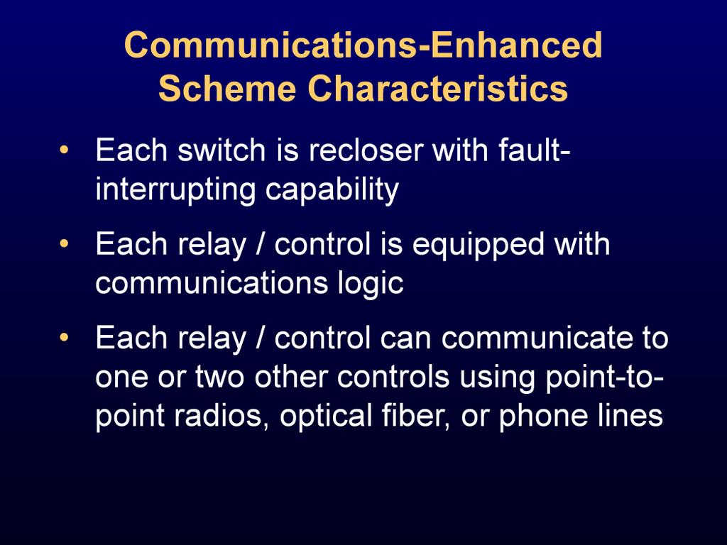
20 Case 2 shows a system with breakers and/or reclosers at positions 1 through 5. Each switch is capable of interrupting fault current. Further, we add a relay, or control, to each switch and a communications line between each relay. This allows SW2 to be opened automatically and SW5 to be closed automatically, thereby eliminating the additional time to restore load if there is a permanent fault on Line 1. Using intelligent devices that communicate with each other allows the devices to quickly determine how to reconfigure the system to isolate the faulted line and restore power to unfaulted lines. 20

21 For Case 1, we assume that it takes 0.5 hours to operate each switch manually. The time includes travel time and any time needed for conversations with system operators. Thus, for the permanent fault on Line 1, we assume a 1-hour restoration time. For Case 2, we assume a 5-second delay to send a trip signal to SW2 and a 1-second delay to send a close signal to SW5, for a 6-second restoration time. These times can be faster depending on the communications and switch equipment. The 5 second and 1 second time delays used are simply an example. Next, we compare the reliability of these two schemes. 21

22 To compare the reliability of the two schemes, we calculate the unavailability of load served to Line 2 customers for permanent faults on Line 1 or Line 2 using fault tree analysis. The unavailability of service is defined as the mean time to repair divided by the mean time between failures. For our example, we made the following assumptions: 0.2 permanent line faults per year 3 hours to repair the line 0.01 breaker or switch failures per year 1 hour to repair a breaker or switch We used the IEEE Gold Book for the reliability data. If the utility has more accurate data, substitute those numbers in the fault tree calculations, which can be found in Appendix I of the paper Trip and Restore Distribution Circuits at Transmission Speeds. To illustrate this equation, we assume it takes 3 hours to repair a line after a permanent fault, and 0.2 permanent faults occur per year (MTBF = 1/0.2 = 5). Thus the unavailability is 3 hours divided by 5 years. 22
23 The diagram on this slide is the fault tree for Line 2 load not served because of permanent faults on Lines 1 or 2. All of the unavailability numbers are multiplied by The OR gate simply sums all of the unavailability values: Line 1 fault with switches OK, SW2 bad, and SW5 bad and Line 2 fault with switches OK and SW2 bad. The value 140 is not an absolute reliability but is useful when making comparisons to other schemes to show relative reliability. 23

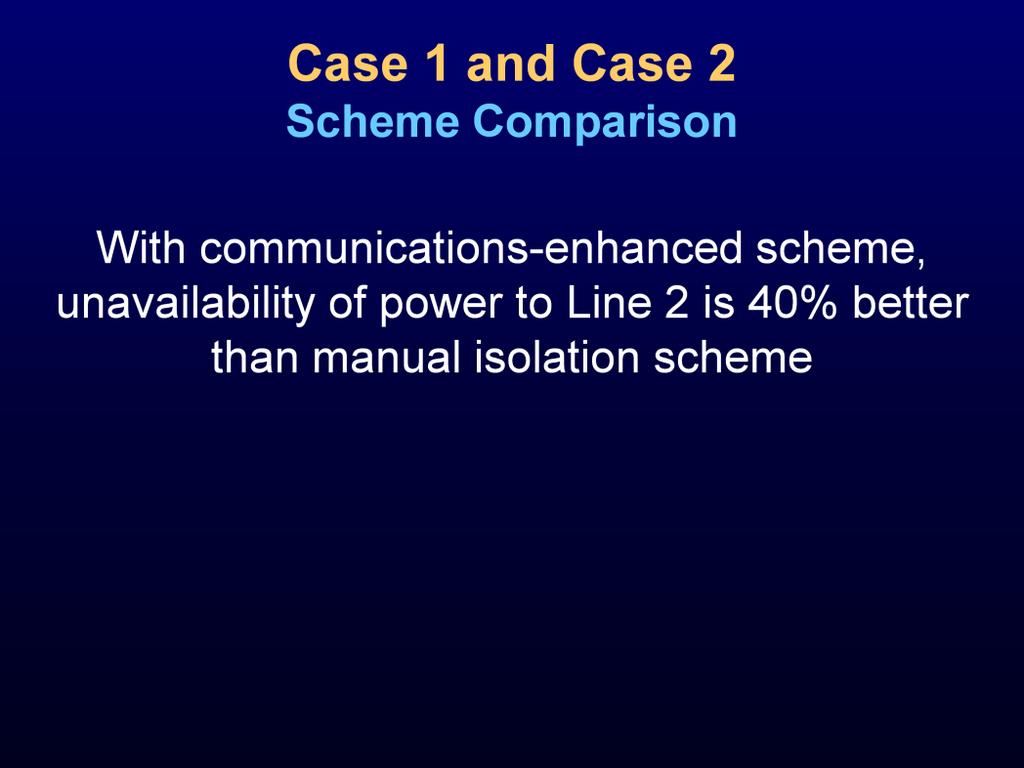
24 For the same conditions as on the previous slide, the automatic scheme has an unavailability of 86, which is better than the 140 obtained with the manual scheme. This improvement results from the time saved by using intelligent devices and communications to trip and close switches instead of relying on manual operation. 24
25 25

26 The figure on this slide is a power acceptability curve. The shaded region above and below the lines defines the unacceptable voltage variation region (UVVR). For example, a load defined by this curve can withstand an 80 percent voltage for 0.5 seconds. These power acceptability curves are also referred to as CBEMA (Computer and Business Electrical Manufacturers Association) and FIPS (Federal Information Processing Standard) curves. There is no universal standard for power acceptability curves. Reasons for this include the following: Different loads have different tolerances-to-voltage variations. This means that we cannot use a standard curve. Power acceptability curves do not consider multiple voltage variations that occur in rapid succession. A single voltage variation may be tolerable but a second voltage variation that occurs very close to the first may not be tolerable. Power acceptability curves also do not account for load recovery time. 26

27 In the IEEE Gold Book, a survey shows that 25 percent of industrial plants must completely restart production if service is interrupted for greater than 10 cycles. The same survey shows that the average restart time is 17 hours. This should motivate us to find ways to trip and restore load faster. 27

28 The diagram on this slide shows a system one-line diagram for a rural distribution feeder. To meet the coordination requirements, Relay 1 needs to coordinate with the slowest downstream device, which in this case is Relay 2. Likewise, Relay 2 must coordinate with its slowest downstream device, which is a 50T fuse. 28
29 The chart on this slide shows time current characteristics for the system. Note that Relay 1 coordinates with Relay 2 and the 50T fuse. However, for faults on the Line 1, Relay 1 provides slower clearing than would be possible if the relay only needed to coordinate with the 25T fuse. As shown, Relay 1 trips in about one second for a 2000 A fault. 29

30 Communications between Relays 1 and 2 reduce tripping times for Line 1 faults. For example, Relay 1 no longer must time-coordinate with Relay 2 if communications are present. Instead, Relay 1 now must only coordinate with fuses tapped off of Line 1. In this scheme, Relay 1 uses two time-overcurrent elements one that coordinates with Relay 2 if the communications channel is not in service and another that coordinates with the 25T fuse when the channel is available. The communications channel and the supporting logic in Relays 1 and 2 allow Relay 1 to discern when a fault is downstream from Recloser R. For faults downstream from Recloser R, Relay 2 senses the fault and instructs Relay 1 not to trip using its fast timeovercurrent element. If Relay 2 does not sense a fault in the forward direction while Relay 1 does, then the fault must be on Line 1 or on a Line 1 lateral. For such faults, Relay 1 does not receive a block signal and is permitted to trip using its fast time-overcurrent element. With this scheme, the Relay 1 fast time-overcurrent element is only required to time-coordinate with the 25T fuse. To handle contingencies such as a communications failure between Relay 1 and Relay 2 or failure of the downstream recloser, some level of backup protection may be desired. For these reasons, the time-delayed curve for Relay 1 can also be left enabled as backup protection. 30

31 The chart on this slide shows the improved time-current coordination. Note that the trip time is reduced to about 0.2 seconds for a 2000 A fault. This is a significant reduction from the 1-second trip time without communications. It also reduces voltage sag on this feeder and adjacent feeders. 31

32 Next, we examine the implementation of the two schemes: A conventional scheme using relays or controls with standard voltage transformers and some associated logic. A communications-enhanced scheme that allows communication between each of the protection devices. 32

33 Here is a one-line system diagram. SW1, SW2, SW3, and SW4 are normally closed. SW5 is normally open. 33

34 The table on this slide shows the switching operations required to restore load for a particular faulted line section. 34

35 One method of reducing restoration times and directly improving traditional reliability data (SAIDI, CAIDI) is to use conventional microprocessor-based relays and/or recloser controls at each switch location with voltage signals supplied from voltage transformers on each side of the switch. This enables us to detect hot/dead voltage conditions, thereby allowing automatic tripping and restoration of switches and improving speed and reliability. 35

36 The equipment requirements and capabilities for the conventional scheme are described on this slide. 36
.")
37 In this example, each relay uses voltage elements to declare dead or hot voltage (e.g., DL indicates dead voltage on Line 2 and HL4 indicates hot voltage on Line 4). The top portion of the figure on this slide ensures that Line 2 load is restored after a Line 1 fault. This occurs when: Voltage was initially hot on both sides of SW2 (HL1 HL2). Voltage goes dead (DL1 DL2). SW2 is closed. A 50 element at SW2 is not picked up (a security check for bolted three-phase faults). Conditions 1 through 4 are true for tt2 time (which is greater than the maximum total reclosing time for SW1, about 90 to 120 seconds, depending on reclosing delays). The lower portion is to restore Line 1 for Line 2 faults. If the 50 element at SW2 picked up and dropped out twice and conditions 1 through 4 are true for tt2a time (set less than the third reclosing interval at SW1, about 5 to 10 seconds), then trip SW2. If the fault is on Line 1, we trip SW2 after SW1 has completed its reclosing sequence. If the fault is on Line 2, we trip SW2 before SW1 advances to lockout. 37
38 The closing logic for SW5 requires that the following conditions be true for tc5 time: Voltage is initially hot on both sides of SW5 (HL4 HL2). Voltage goes dead on Line 2 (HL4 DL2). SW5 is open. SW5 did not trip after a restoration close attempt. Set tc5 greater than tt2. 38
39 Finally, if the fault on Line 2 is permanent, we need to avoid another reclosing sequence from SW3 after SW5 has been closed. Thus, if the voltages are dead (DL2 DL4) after a close attempt by SW5, the logic trips SW5 before SW3 recloses. We also need to put a short time delay for the first reclosing attempts at SW1 and SW3 to allow time for a SW5 trip after a close attempt. The disadvantage of this scheme is that it is possible to close into a permanent fault on Line 2 and momentarily disrupt service to Lines 3 and 4 when we attempt to restore the load on Line 2. 39

40 The diagram on this slide shows a communications-enhanced restoration scheme. 40
41 41
42 Fast tripping is enabled for SW1 if the communications circuit is healthy and SW2 is open. If SW2 is closed, the instantaneous element of SW2 will block the fast tripping of SW1 for a fault on Line 2. 42
43 For permanent faults on Line 1, it is desirable to open SW2 and close SW5 in order to restore power to the customers on Line 2. This is accomplished by noting that the instantaneous element of SW1 was picked up via the rising edge, but is now not asserted, and SW1 is open. This also requires the communications circuit to be healthy. 43

44 After SW2 is open, SW5 is closed to restore power to Line 2. This is accomplished by checking that SW2 is open, verifying there is no current flowing through SW2, and that the SW1 instantaneous element has operated. As before, the communications circuit must be healthy because it is the means by which the information is passed from device to device. 44

45 For a fault on Line 1, we wish to restore the critical load on Line 2 as quickly as possible. When Relay 1 senses the fault, it sends a signal to Relay 2, which in turn sends a signal to Relay 5. Relay 2 trips SW2 and Relay 5 closes SW5 as quickly as possible to restore power to the critical load. Meanwhile, Relay 1 can trip via its own fast curve to clear the fault. 45

46 The diagram on this slide shows the timing diagram for the fast trip and restoration. How fast can we trip and restore load to Line 2 after a fault on Line 1? Can we meet the 10-cycle service interruption requirement. Relay 1 overcurrent elements can be set sensitively to operate in 0.25 to 0.5 cycles. If we apply optical fiber, the communications delay to send the signal to Relay 2 (Comm 1-2) is negligible. Assuming it takes 0.25 cycles (not shown) for Relay 2 to process the signal, then, the Comm 2-5 time is virtually zero. It takes Relay 5 another 0.25 cycles (not shown) to process the signal, then it issues a close signal to SW5. Thus, it takes about 1 cycle ( ) from fault inception to close assertion at SW5. This leaves 9 cycles for SW5 to close to meet the 10-cycle criterion. If we use spread-spectrum radios instead, we must allow about 20 milliseconds each for times Comm 1-2 and Comm 2-5. Thus, it takes about 56 milliseconds (20 ms + 20 ms + 1 cycle) or about 3 1/2 cycles from fault inception to SW5 close assertion. 46

47 Observation of the restoration times for the conventional and communications schemes, shows that: For a fault on Line 1, the conventional scheme can improve the traditional indices, SAIDI and CAIDI, for load served to Line 2. SW1 trips and recloses three times to lockout, then timer tt2 times out to trip SW2, and tc5 times to close SW5. Depending on the reclose open interval times, we can usually restore load in 1 to 2 minutes. For the communications scheme, SW1 also trips and recloses three times to lockout. However, we can significantly improve power quality by reducing the restoration times of Line 2 load to delays close to 10 cycles (SW2 trip, SW5 close). 47
, we can change setting groups to")
48 If the communications link fails, we resume normal coordination. If the system changes (for example, SW2 is normally open), we can change setting groups to accommodate this arrangement. 48

49 Conclusions: Using communications-assisted protection and control schemes for distribution circuits significantly reduces trip and load transfer times. Traditional performance indices do not consider the reduction in service reliability caused by fault-induced voltage sags. Considering the effects of these sags on customer loads in the immediate vicinity of a fault, we conclude that we must also consider new protection and control methods that reduce sag duration to cycles instead of seconds. Fault tree analysis shows that upgrading breaker and recloser controls with communications scheme logic realized a 40 percent improvement in service unavailability (compared with traditional distribution protection and control). Communications-assisted trip logic simplifies difficult time-coordination applications by limiting the number of devices requiring coordination. This simplification also decreases tripping time for main-line faults. Without a communications channel, we can apply relay logic that combines voltage elements, switch status, and other logic to improve service reliability for unfaulted feeders served by a faulted source. 49
FORENSIC CASEBOOK. By Bob Huddleston, Eastman Chemical Co. One of the most common. reasons for marriage failure
 The Case of the Energized Cable Cutting Incident How miscommunication leads to an electrical helper slicing through live 13.8kV cable and miraculously walking away to tell about it By Bob Huddleston, Eastman
REFURBISHMENT OF SECONDARY SYSTEMS IN HIGH VOLTAGE SUBSTATIONS LESSONS LEARNED IN VENEZUELA
 21, rue d'artois, F-75008 Paris http://www.cigre.org B3-110 Session 2004 CIGRÉ REFURBISHMENT OF SECONDARY SYSTEMS IN HIGH VOLTAGE SUBSTATIONS LESSONS LEARNED IN VENEZUELA by E. PADILLA * L. CEDEÑO E. PELAYO
PRINCIPLES AND APPLICATIONS
 GENERATION & NETWORK Digital Automation Measuring and Control Devices AMS7000 PROCOM The optimum operation of an electrical network depends particularly on the reliability and the availability of the protection,
British Columbia Utilities Commission (BCUC) British Columbia Hydro and Power Authority (BC Hydro)
 British Columbia Hydro and Power Authority (BC Hydro)") BC hydro 1f au Joanna Sofield Chief Regulatory Offcer Phone: (604) 623-4046 Fax: (604) 623-4407 bchydroregulatory. group(ßbchydro. com May 04, 2007 Mr. Robert J. Pellatt Commission Secretary British Columbia
BC hydro 1f au Joanna Sofield Chief Regulatory Offcer Phone: (604) 623-4046 Fax: (604) 623-4407 bchydroregulatory. group(ßbchydro. com May 04, 2007 Mr. Robert J. Pellatt Commission Secretary British Columbia
Circuit Reliability Review
 Circuit Reliability Review Rancho Santa Margarita January 2018 Building a Smarter Grid for Southern California Southern California Edison is developing an electric grid to support California s transition
EE201: Transmission Line Protection
 EE201: Transmission Line Protection EE201 Rev.001 CMCT COURSE OUTLINE Page 1 of 5 Training Description: Engineers and power system consultants who need a comprehensive understanding of the challenges and
Improved Synchronization System for Thermal Power Station
 Improved Synchronization System for Thermal Power Station Lokeshkumar.C 1, Logeshkumar.E 2, Harikrishnan.M 3, Margaret 4, Dr.K.Sathiyasekar 5 UG Students, Department of EEE, S.A.Engineering College, Chennai,
Zero Crossover Dynamic Power Synchronization Technology Overview
 Technical Note Zero Crossover Dynamic Power Synchronization Technology Overview Background Engineers have long recognized the power benefits of zero crossover (Figure 1) over phase angle (Figure 2) power
Medium and High Voltage Circuit Breakers Characteristic Time Quantities of the Circuit Breaker with Applications
 Workshop 6: Maintenance and monitoring Medium and High Voltage Circuit Breakers Characteristic Time Quantities of the Circuit Breaker with Applications Alexander Herrera OMICRON electronics GmbH 3 December
Reliability Guideline: Generating Unit Operations During Complete Loss of Communications
 Reliability Guideline: Generating Unit Operations During Complete Loss of Communications Preamble It is in the public interest for the North American Electric Reliability Corporation (NERC) to develop
Improving Lightning Protection of Power Systems with Externally Gapped Line Arresters (EGLA)
") Improving Lightning Protection of Power Systems with Externally Gapped Line Arresters (EGLA) Jonathan Woodworth ArresterWorks 1 Today's Presentation 1. Real Value of Arresters 2. Improving Distribution
Improving Lightning Protection of Power Systems with Externally Gapped Line Arresters (EGLA) Jonathan Woodworth ArresterWorks 1 Today's Presentation 1. Real Value of Arresters 2. Improving Distribution
Toronto Hydro - Electric System
 Toronto Hydro - Electric System FIT Commissioning Requirements and Reports Comments and inquiries can be e-mailed to: FIT@torontohydro.com Customers without e-mail access can submit through regular mail
APPLICATION OF POWER SWITCHING FOR ALTERNATIVE LAND CABLE PROTECTION BETWEEN CABLE LANDING STATION AND BEACH MAN HOLE IN SUBMARINE NETWORKS
 APPLICATION OF POWER SWITCHING FOR ALTERNATIVE LAND PROTECTION BETWEEN LANDING STATION AND BEACH MAN HOLE IN SUBMARINE NETWORKS Liyuan Shi (Huawei Marine Networks) Email: Huawei
An Analysis of a Permissive Overreaching Transfer Trip Scheme at a 120kV Substation
 An Analysis of a Permissive Overreaching Transfer Trip Scheme at a 120kV Substation Russell Louie and Mehdi Etezadi-Amoli Abstract This paper describes a post fault investigation into an undesired operation
Circuit Reliability Review
 Circuit Reliability Review La Verne January 2018 Building a Smarter Grid for Southern California Southern California Edison is developing an electric grid to support California s transition to a clean
Removal of Decaying DC Component in Current Signal Using a ovel Estimation Algorithm
 Removal of Decaying DC Component in Current Signal Using a ovel Estimation Algorithm Majid Aghasi*, and Alireza Jalilian** *Department of Electrical Engineering, Iran University of Science and Technology,
Definitions. Common Corridor:
 Definitions Common Corridor: Contiguous right-of-way or two parallel right-of-ways with structure centerline separation less than the longest span length of the two transmission circuits at the point of
Mitigation of Cascading Outages and Prevention of Blackouts:System-Wide Corrective Control
 10th Mediterranean Conference on Power Generation, Transmission, Distribution and Energy Conversion 6-9 November 2016 Belgrade, Serbia Mitigation of Cascading Outages and Prevention of Blackouts:System-Wide
MICROMASTER Encoder Module
 MICROMASTER Encoder Module Operating Instructions Issue 01/02 User Documentation Foreword Issue 01/02 1 Foreword Qualified Personnel For the purpose of this Instruction Manual and product labels, a Qualified
MANAGING POWER SYSTEM FAULTS. Xianyong Feng, PhD Center for Electromechanics The University of Texas at Austin November 14, 2017
 MANAGING POWER SYSTEM FAULTS Xianyong Feng, PhD Center for Electromechanics The University of Texas at Austin November 14, 2017 2 Outline 1. Overview 2. Methodology 3. Case Studies 4. Conclusion 3 Power
FINAL REPORT LOAD SHEDDING IN TASMANIA ON 20 DECEMBER 2016 REVIEWABLE OPERATING INCIDENT REPORT FOR THE NATIONAL ELECTRICITY MARKET
 FINAL REPORT LOAD SHEDDING IN TASMANIA ON 20 DECEMBER 2016 REVIEWABLE OPERATING INCIDENT REPORT FOR THE NATIONAL ELECTRICITY MARKET Published: 6 April 2017 IMPORTANT NOTICE Purpose AEMO has prepared this
Design of Fault Coverage Test Pattern Generator Using LFSR
 Design of Fault Coverage Test Pattern Generator Using LFSR B.Saritha M.Tech Student, Department of ECE, Dhruva Institue of Engineering & Technology. Abstract: A new fault coverage test pattern generator
SITE All work shall be performed at Center Park Substation (1895 Kernan Blvd, Jacksonville, Fl ). DATE: 04/03/2018
. DATE: 04/03/2018") DATE: 04/03/2018 TO: The Contractor FROM: System Protection & Control Projects 20413 SUBJECT: Technical Specifications for Center Park APSTF Project PROJECT OVERVIEW This is a general specification that
DATE: 04/03/2018 TO: The Contractor FROM: System Protection & Control Projects 20413 SUBJECT: Technical Specifications for Center Park APSTF Project PROJECT OVERVIEW This is a general specification that
Real Time Monitoring for SMART Grid Initiatives Synchronized Measurement & Analysis in Real Time SMART program by
 Real Time Monitoring for SMART Grid Initiatives Synchronized Measurement & Analysis in Real Time SMART program by Bharat Bhargava Armando Salazar Southern California Edison Co. IEEE PES General Meeting
SEL-251 SEL SEL DISTRIBUTION RELAY
 SEL-251 SEL-251-2 SEL-251-3 DISTRIBUTION RELAY PHASE OVERCURRENT RELAY WITH VOLTAGE CONTROL NEGATIVE-SEQUENCE OVERCURRENT RELAY GROUND OVERCURRENT RELAY MULTIPLE SHOT RECLOSING RELAY SELECTABLE SETTING
SIPROTEC 5 Application Note
 www.siemens.com/protection SIPROTEC 5 Application Note SIP5-APN-018: Answers for infrastructure and cities. SIPROTEC 5 - Application: SIP5-APN-018 Breaker-and-a-half Automatic reclosing and leader follower
PRELIMINARY Sunny Boy 240-US
 PRELIMINARY Sunny Boy 240-US SB 240-US-10 Optimized reliability Simple installation Unrivaled monitoring SMA-backed security Multigate technology allows for reduced component count Private band powerline
Experiences of CESC in Smart Grid Initiatives LT Network Automation. Anjan Mitra / Arka Ghosh
 Experiences of CESC in Smart Grid Initiatives LT Network Automation Anjan Mitra / Arka Ghosh CESC An Overview About 120 year old fully Integrated Energy Utility Oldest private electricity utility in India
Avoiding False Pass or False Fail
 Avoiding False Pass or False Fail By Michael Smith, Teradyne, October 2012 There is an expectation from consumers that today s electronic products will just work and that electronic manufacturers have
THE FUTURE OF NARROWCAST INSERTION. White Paper
 THE FUTURE OF NARROWCAST INSERTION White Paper May/2013 The future of narrowcast insertion Next generation, CCAP compliant RF combining This paper looks at the advantages of using the converged cable access
Factory configured macros for the user logic
 Factory configured macros for the user logic Document ID: VERSION 1.0 Budapest, November 2011. User s manual version information Version Date Modification Compiled by Version 1.0 11.11.2011. First edition
A Unique Power Supply for the PEP II Klystron at SLAC*
 I : SLAC-PUB-7591 July 1997 A Unique Power Supply for the PEP II Klystron at SLAC* R. Case1 and M. N. Nguyen Stanford Linear Accelerator Center Stanford University, Stanford, CA 94309 Presented at the
Breaker-and-a-half Automatic reclosing and leader follower.
 Breaker-and-a-half Automatic reclosing and leader follower www.siemens.com/siprotec SIPROTEC 5 Application Breaker-and-a-half Automatic reclosing and leader follower APN-018, Edition 1 Content 1... 3 1.1
Advanced Return Path Alignment & Maintenance Using the 9581 SST R4
 Advanced Return Path Alignment & Maintenance Using Introduction The first step in developing a successful alignment and maintenance strategy for the return path depends on understanding what constitutes
Center For The Arts Towson, Maryland
 Electrical Depth Introduction For the Electrical portion of this report, several panelboards on the Third Floor were analyzed and examined to combine and move loads to reduce the number of panelboards.
V9A01 Solution Specification V0.1
 V9A01 Solution Specification V0.1 CONTENTS V9A01 Solution Specification Section 1 Document Descriptions... 4 1.1 Version Descriptions... 4 1.2 Nomenclature of this Document... 4 Section 2 Solution Overview...
FLIP-FLOPS AND RELATED DEVICES
 C H A P T E R 5 FLIP-FLOPS AND RELATED DEVICES OUTLINE 5- NAND Gate Latch 5-2 NOR Gate Latch 5-3 Troubleshooting Case Study 5-4 Digital Pulses 5-5 Clock Signals and Clocked Flip-Flops 5-6 Clocked S-R Flip-Flop
AMERICAN NATIONAL STANDARD
 Interface Practices Subcommittee AMERICAN NATIONAL STANDARD ANSI/SCTE 108 2018 Test Method for Dielectric Withstand of Coaxial Cable NOTICE The Society of Cable Telecommunications Engineers (SCTE) / International
WELDING CONTROL UNIT: TE 450 USER MANUAL
 j WELDING CONTROL UNIT: TE 450 USER MANUAL RELEASE SOFTWARE No. 1.50 DOCUMENT NUMBER: MAN 4097 EDITION: MARCH 1998 This page is left blank intentionally. 2 / 34 TABLE OF CONTENTS SUBJECTS PAGE WELDING
1C.5.1 Voltage Fluctuation and Flicker
 2 1 Ja n 1 4 2 1 J a n 1 4 Vo l.1 -Ge n e r a l;p a r tc-p o we r Qu a lity 1. Scope This document contains guidelines regarding maximum acceptable levels of voltage fluctuation and light flicker in the
3200NT System 14. Service Manual. IMPORTANT: Fill in Pertinent Information on Page 3 for Future Reference
 3200NT System 14 Service Manual IMPORTANT: Fill in Pertinent Information on Page 3 for Future Reference Table of Contents Job Specification Sheet... 3 Timer Operation... 4 System Operation In Service...
BLUNIK II ACCESSORIES SPORT DRIVE SPORT CALCULATOR... 49
 USER GUIDE 12/2016 2 INDEX DESCRIPTION of BLUNIK II...6 DESCRIPTION of parameters...7 ADJUSTMENT OF PARAMETERS...7 Parameter: CLOCK SYNCHRO...8 Parameter: TIRES...9 Parameter: CALIBRATION... 10 Calibration
Exercise 4-2. Counting of Actuator Cycles EXERCISE OBJECTIVE & & &
 Exercise 4-2 EXERCISE OBJECTIVE To describe the operation of an electrical counter; To assemble and test a continuous reciprocation system; To extend and retract a cylinder a definite number of times using
FOGGY DOCSIS AN ENABLENCE ARTICLE WRITTEN BY JIM FARMER, CTO APRIL,
 FOGGY DOCSIS AN ENABLENCE ARTICLE WRITTEN BY JIM FARMER, CTO APRIL, 2010 www.enablence.com The whole cable industry is in a fog. It used to be just me in the fog, but since I saw the light and went over
Bulletin 190 IEC Modular Starter System
 Bulletin 90 Table of Contents Selection Guide Description Page Bulletin 90....................................... Accessories....................................... 7 Specifications.....................................
3214NXT. Service Manual. IMPORTANT: Fill in Pertinent Information on Page 3 for Future Reference
 3214NXT Service Manual IMPORTANT: Fill in Pertinent Information on Page 3 for Future Reference Table of Contents Job Specification Sheet 3 Timer Operation 4 System Operation in Service 6 Flow in a Four-Unit
Aqua Turf International, Inc.
 Satellite Versus Decoder Control System During the irrigation design process a decision must be made whether to chose a satellite or decoder style control system. The decision must be made soon after the
Specification. NGTS Issue 1 October 1993
 The Electrical Standards for SHE Transmission s area are non-maintained versions of National Grid Technical Specifications that are applicable to the SHE Transmission System only. These specific versions
Full Disclosure Monitoring
 Full Disclosure Monitoring Power Quality Application Note Full Disclosure monitoring is the ability to measure all aspects of power quality, on every voltage cycle, and record them in appropriate detail
Safety Codes Council Conference Banff C Panel Discussion
 Safety Codes Council Conference Banff 2014 90 C Panel Discussion Tim Driscoll OBIEC Consulting Ltd. George Morlidge Fluor Canada Ltd. Scott Basinger Eaton Canada René Leduc Marex Canada Limited Perspectives
Incorrect Temperature Measurements: The Importance of Transmissivity and IR Viewing Windows
 Incorrect Temperature Measurements: The Importance of Transmissivity and IR Viewing Windows Abstract IR viewing windows save lives. Most Thermographers today are thankful to perform their scans without
Sentinel I24 Digital Input and Output Configuration
 Application Bulletin: #155 Date: October 19, 2007 Sentinel I24 Digital Input and Output Configuration The Sentinel I24 can communicate with external hardware using digital inputs and outputs. There are
8000 Plus Series Safety Light Curtain Installation Sheet ( CD206A/ CD206B )
") SMARTSCAN 8000 PLUS LIGHT CURTAIN 1 Unpacking 8000 Plus Series Safety Light Curtain Installation Sheet ( CD206A/0160306 CD206B160306 ) Remove all packaging material and retain it Locate and keep the delivery
SMARTSCAN 8000 PLUS LIGHT CURTAIN 1 Unpacking 8000 Plus Series Safety Light Curtain Installation Sheet ( CD206A/0160306 CD206B160306 ) Remove all packaging material and retain it Locate and keep the delivery
Timing Error Detection: An Adaptive Scheme To Combat Variability EE241 Final Report Nathan Narevsky and Richard Ott {nnarevsky,
 Timing Error Detection: An Adaptive Scheme To Combat Variability EE241 Final Report Nathan Narevsky and Richard Ott {nnarevsky, tomott}@berkeley.edu Abstract With the reduction of feature sizes, more sources
I r A Protection against direct contact Finger and back of hand proof to VDE 0106 Part 100
 DATASHEET - NZMH2-A100 Circuit-breaker, 3p, 100A Part no. NZMH2-A100 Catalog No. 259099 Similar to illustration Delivery program Product range Circuit-breaker Protective function System and cable protection
Generator protection relay
 Page 1 Issued: April 1999 Status: New Data subject to change without notice Features Off-the-shelf generator protection relay for small and medium sized power generators Three-phase time overcurrent and
Aerial Cable Installation Best Practices
 Aerial Cable Installation Best Practices Panduit Corp. 2007 BEST PRACTICES Table of Contents 1.0 General... 3 2.0 Introduction... 3 3.0 Precautions... 4 4.0 Pre-survey... 5 5.0 Materials and Equipment...
Review of the Comcast. Fort Collins Cable System. Technical Characteristics
 Review of the Comcast Fort Collins Cable System Technical Characteristics Prepared by: January 30, 2004 Dick Nielsen Senior Engineer CBG Communications, Inc. Introduction and Background CBG Communications,
10/13/2011 Planning Coordination Committee. Standards
 Document name Category System Performance Regional Criterion ( ) Regional Reliability Standard (X) Regional Criterion ( ) Policy ( ) Guideline ( ) Report or other Document date 12/01/2011 Adopted/approved
TEAMS Competition 2014
 TEAMS Competition 2014 Electrical Grid Urban infrastructures throughout the United States are aging. As our demand for electricity grows, so does our need for uninterrupted service for more than 130 million
GA A26497 SOLID-STATE HIGH-VOLTAGE CROWBAR UTILIZING SERIES-CONNECTED THYRISTORS
 GA A26497 SOLID-STATE HIGH-VOLTAGE CROWBAR by J.F. Tooker, P. Huynh, and R.W. Street JUNE 2009 DISCLAIMER This report was prepared as an account of work sponsored by an agency of the United States Government.
SURGE PROTECTIVE DEVICES
 SURGE PROTECTIVE DEVICES COMPANY INTRODUCTION Bridex Singapore Pte Ltd is founded in 1978 as a manufacturer of instruments transformer for the Asian market. We are the first local electrical switchgear
I/A Series Hardware Fiber Optic LAN Converter
 I/A Series Hardware PSS 21H-7F3 B4 The provides bidirectional conversion between coaxial and fiber optic media. The converter is compatible with existing I/A Series system hardware, utilizes industry standard
0.1. Outage Management Process Summary
 0.1 Outage Management Process Summary Issue: 1.0 Issue Date: August 27, 2014 Table of Contents 1. Introduction... 4 1.1 Purpose... 4 1.2 Glossary... 4 State Transition Model... 8 2. Outage Management Processes...
LED control gear Compact dimming. Uconverter LCAI 2x38 W 0500 K013 one4all ECO series. Ordering data
 Product description Dimmable built-in for LED Constant current (with 2 adjustable output channels) Designed for outdoor and street luminaire Output power 2 x 38 W Suitable for mains voltage peaks (burst/surge)
Reducing Waste in a Converting Operation Timothy W. Rye P /F
 Reducing Waste in a Converting Operation Timothy W. Rye P. 770.423.0934/F. 770.424.2554 RYECO Incorporated Trye@ryeco.com 810 Pickens Ind. Dr. Marietta, GA 30062 Introduction According to the principles
EMC Solutions Noise filtering
 Power & Signal Quality TRABTECH EMC Solutions Noise filtering Interference-free power supply and signal transmission A permanent supply and safe data link are essential for the operational reliability
Online Control System Migration of Industrial Centrifuge Project Description
 Canadian Consulting Engineering Awards 2017 Online Control System Migration of Industrial Centrifuge Project Description Category: Natural Resources, Mining, Industry & Energy Fort McMurray, AB Table of
Protective function Systems, cable, selectivity and generator protection. i 2 t constant function: switchable. I r A
 DATASHEET - NZMN3-VE630 Circuit-breaker, 3p, 630A Part no. NZMN3-VE630 Catalog No. 259133 EL-Nummer (Norway) 0004358791 Similar to illustration Delivery program Product range Circuit-breaker Protective
High-Power Amplifier (HPA) Configuration Selection
 Configuration Selection") WHITE PAPER High-Power Amplifier (HPA) Configuration Selection by Kimberly Nevetral Abstract: High Power Amplifier configuration is one of the most important decisions for Satellite Communication (SATCOM)
WHITE PAPER High-Power Amplifier (HPA) Configuration Selection by Kimberly Nevetral Abstract: High Power Amplifier configuration is one of the most important decisions for Satellite Communication (SATCOM)
Dimming actuators GDA-4K KNX GDA-8K KNX
 Dimming actuators GDA-4K KNX GDA-8K KNX GDA-4K KNX 108394 GDA-8K KNX 108395 Updated: May-17 (Subject to changes) Page 1 of 67 Contents 1 FUNCTIONAL CHARACTERISTICS... 4 1.1 OPERATION... 5 2 TECHNICAL DATA...
The 1.2 GHz NCI solution from Technetix:
 The 1.2 GHz NCI solution from Technetix: The future of headend RF signal management The demand for high speed Internet and digital television means that headends are frequently modified, extended and upgraded
Transfer Switch. OTECA (Spec A) OTECB (Spec A) OTECC (Spec A) OTECD (Spec A) Amperes. English Original Instructions (Issue 5)
 OTECB (Spec A) OTECC (Spec A) OTECD (Spec A) Amperes. English Original Instructions (Issue 5)") Operator Manual Transfer Switch 40-1000 Amperes OTECA (Spec A) OTECB (Spec A) OTECC (Spec A) OTECD (Spec A) English Original Instructions 10-2015 962-0131 (Issue 5) Table of Contents 1. SAFETY PRECAUTIONS...
Operator Manual Transfer Switch 40-1000 Amperes OTECA (Spec A) OTECB (Spec A) OTECC (Spec A) OTECD (Spec A) English Original Instructions 10-2015 962-0131 (Issue 5) Table of Contents 1. SAFETY PRECAUTIONS...
BE3-GPR GENERATOR PROTECTIVE RELAY
 BE3-GPR GENERATOR PROTECTIVE RELAY Behind-the-Panel Mounting Semi-flush Mounting Basler Electric s BE3-GPR generator protective relay offers multiple protective features in a single package. Its microprocessor-based
DMX and 4000 air circuit breakers from 800 to 4000 A
 DMX 3 20 and 00 air circuit breakers from 800 to 00 NEW 286 56 + 288 02 (p. 4) 286 4 + 288 02 (p. 4) 28 56 + 288 02 (p. 4) Dimensions (p. to 53) Electrical characteristics (p. 54 to 5) ir circuit breakers
OVERVIEW. YAMAHA Electronics Corp., USA 6660 Orangethorpe Avenue
 OVERVIEW With decades of experience in home audio, pro audio and various sound technologies for the music industry, Yamaha s entry into audio systems for conferencing is an easy and natural evolution.
Contactor Monitoring Relay CMD Cost-Effective Solution for Safe Machines
 Contactor Monitoring Relay CMD Cost-Effective Solution for Safe Machines The complete range of contactors, efficient motor-starters and variable speed drives for the motor circuit. New simple to install
SPECIAL SPECIFICATION 6735 Video Optical Transceiver
 2004 Specifications CSJ 0924-06-244 SPECIAL SPECIFICATION 6735 Video Optical Transceiver 1. Description. This Item governs the furnishing and installation of Video optical transceiver (VOTR) in field location(s)
(Cat. No IJ, -IK)
") (Cat. No. 1771-IJ, -IK) Product Data The Encoder/Counter Module Assembly (cat. no. 1771-IJ or 1771-IK) maintains a count, independent of the processor, of input pulses that may typically originate from
(Cat. No. 1771-IJ, -IK) Product Data The Encoder/Counter Module Assembly (cat. no. 1771-IJ or 1771-IK) maintains a count, independent of the processor, of input pulses that may typically originate from
1 Power Protection and Conditioning
 Power Protection and Conditioning MCR Hardwired Series Power Line Conditioning with Voltage Regulation The MCR Hardwired Series provides excellent noise filtering and surge protection to safeguard connected
MELSEC iq-r Inter-Module Synchronization Function Reference Manual
 MELSEC iq-r Inter-Module Synchronization Function Reference Manual SAFETY PRECAUTIONS (Read these precautions before using this product.) Before using MELSEC iq-r series programmable controllers, please
Operating Instructions
 CNTX Contrast sensor Operating Instructions CAUTIONS AND WARNINGS SET-UP DISTANCE ADJUSTMENT: As a general rule, the sensor should be fixed at a 15 to 20 angle from directly perpendicular to the target
Series CT7N Bimetallic Overload Relays
 Series CT7N imetallic Overload Relays Choose CT7N overloads in DC applications and when monitoring Variable Frequency Drives Sprecher + Schuh has always paid particular attention to the subject of motor
Report on Comments June 2013 NFPA 70
 10-1 Log #1392 NEC-P10 Dennis Darling, Stantec Consulting Ltd. 10-5 Delete text to read as follows: Localization of an overcurrent condition to restrict outages to the circuit or equipment affected, accomplished
ORDERING Page 6 BASLER RELAY STANDARDS, DIMENSIONS, ACCESSORIES Request bulletin SDA
 BE1-59NC CAPACITOR NEUTRAL OVERVOLTAGE RELAY The BE1-59NC Capacitor Neutral Overvoltage Relay provides sensitive protection for capacitor banks. ADDITIONAL INFORMATION INSTRUCTION MANUAL ADVANTAGES Helps
ORDERING Page 6 STANDARDS, DIMENSIONS and ACCESSORIES Request bulletin SDA
 BE1-59NC CAPACITOR NEUTRAL OVERVOLTAGE RELAY The BE1-59NC Capacitor Neutral Overvoltage Relay provides sensitive protection for capacitor banks. ADVANTAGES Helps avoid cascading capacitor failures. Sensing
SEL-3405 High-Accuracy IRIG-B Fiber-Optic Transceiver
 SEL-3405 High-Accuracy IRIG-B Fiber-Optic Transceiver Accurate IRIG-B Over Fiber Optics Major Features and Benefits The SEL-3405 High-Accuracy IRIG-B Fiber-Optic Transceiver can send high-accuracy demodulated
Images for life. Nexxis for video integration in the operating room
 Images for life Nexxis for video integration in the operating room A picture perfect performance Nexxis stands for video integration done right. Intuitive, safe, and easy to use, it is designed to meet
Scan. This is a sample of the first 15 pages of the Scan chapter.
 Scan This is a sample of the first 15 pages of the Scan chapter. Note: The book is NOT Pinted in color. Objectives: This section provides: An overview of Scan An introduction to Test Sequences and Test
THE ASTRO LINE SERIES GEMINI 5200 INSTRUCTION MANUAL
 THE ASTRO LINE SERIES GEMINI 5200 INSTRUCTION MANUAL INTRODUCTION The Gemini 5200 is another unit in a multi-purpose series of industrial control products that are field-programmable to solve multiple
ALM-6813/6812 INSTALLATION AND PROGRAMMING MANUAL
 ALM-6813/6812 INSTALLATION AND PROGRAMMING MANUAL Installation and programming Manual v2.2 1 MARSS Solar Defender SYSTEM This guidebook provides the essential instructions to install and configure the
A. Introduction 1. Title: Automatic Underfrequency Load Shedding Requirements
 DRAFT 6 V4 Standard PRC-006- RFC-01 01/11/11 A. Introduction 1. Title: Automatic Underfrequency Load Shedding Requirements Deleted: Deleted: 10 Deleted: 20 9 2. Number: PRC 006 RFC 01. Purpose: To establish
User Manual CC DC 24 V 5A. Universal Control Unit UC-1-E. General Information SET. Universal Control Unit UC-1 Of Central Lubrication PAUSE CONTACT
 Universal Control Unit UC-1-E User Manual General Information Universal Control Unit UC-1 Of Central Lubrication CC DC 24 V 5A / M 15 SL /MK 31 M Z 30 General Information Contents Universal Control Unit
Re-defining the utility-scale inverter
 Re-defining the utility-scale inverter We believe in green energy in the ability to meet and contribute to growing power demand while supporting a smart grid that serves a smart society. Solution at a
Notes Generator Verification SDT Project
 Notes Generator Verification SDT Project 2007-09 FERC Office 888 First Street, NE Washington, DC 20426 1. Administration a. The following were in attendance: Bob Snow, Cynthia Pointer, Lim Hansen, Keith
Gamma instabus. Technical product information
 Gamma instabus Technical product information Universal dimmer N 554D31, 4 x 300 VA / 1x 1000 VA, AC 230 V Universal dimmer N 554D31 Control of dimmable lamps, including LED without minimum load Output
Project Summary EPRI Program 1: Power Quality
 Project Summary EPRI Program 1: Power Quality April 2015 PQ Monitoring Evolving from Single-Site Investigations. to Wide-Area PQ Monitoring Applications DME w/pq 2 Equating to large amounts of PQ data
Justifying the Proactive Replacement of Cable
 1 Justifying the Proactive Replacement of Cable Le Xu, Member, IEEE and Richard E. Brown, Fellow, IEEE Abstract Many utilities have aging underground cable systems that are failing at an increasing rate.
AUTOMATIC VIDEO LOSS A/B SWITCH
 CG-X AUTOMATIC VIDEO LOSS A/B SWITCH INSTRUCTION BOOK IB647502 TABLE OF CONTENTS DESCRIPTION 2 MOUNTING INSTRUCTIONS 3 HOW TO CABLE THE CG-X 3 POWER SUPPLY INSTALLATION 3 OPERATION 3 CARE AND MAINTENANCE
TIME-COMPENSATED REMOTE PRODUCTION OVER IP
 TIME-COMPENSATED REMOTE PRODUCTION OVER IP Ed Calverley Product Director, Suitcase TV, United Kingdom ABSTRACT Much has been said over the past few years about the benefits of moving to use more IP in