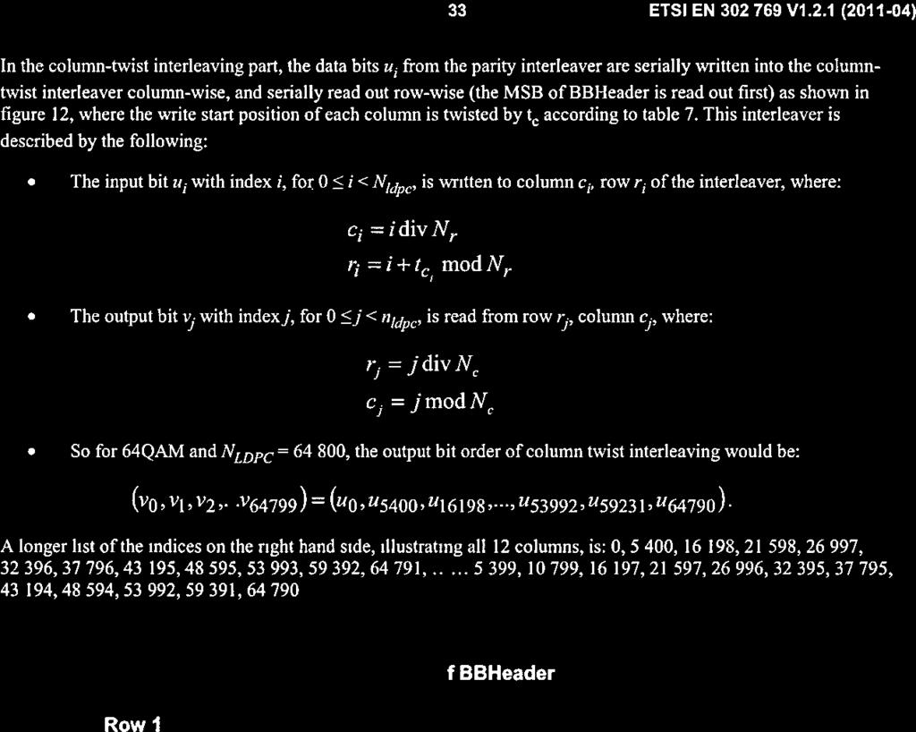
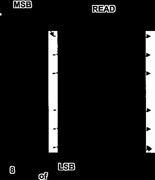
436
|
|
|
- Thomasina Flynn
- 6 years ago
- Views:
Transcription


1 435


2 436


3 437


4 438

5 439

6 440

7 441

8 442

9 443

10 444

11 445

12 446

13 447

14 448

15 449


16 450

17 451

18 452

19 453

20 454

21 455

22 456

23 457


24 458

25 459


26 460

27 461

28 462

29 463

30 464

31 465


32 466


33 467

34 468

35 469

36 470

37 471


38 472

39 473

40 474

41 475

42 476

43 477

44 478

45 479


46 480

47 481

48 482

49 483

50 484

51 485


52 486

53 487

54 488

55 489

56 490

57 491

58 492


59 493


60 494

61 495

62 496


63 497


64 498


65 499


66 500


67 501

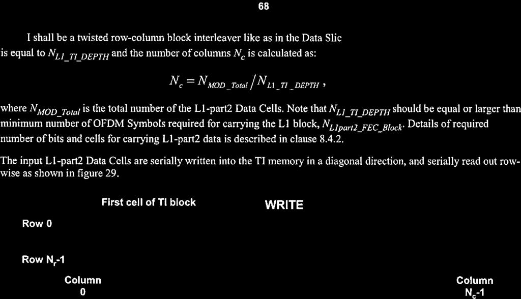


68 502

69 503

70 504


71 505

72 506

73 507

74 508

75 509

76 510


77 511

78 512


79 513

80 514

81 515

82 516

83 517

84 518

85 519

86 520

87 521

88 522

89 523

90 524

91 525

92 526

93 527

94 528

95 529

96 530

97 531

98 532

99 533

100 534

101 535

102 536


103 537

104 538


105 539

106 540


107 541


108 542

109 543

110 544

111 545
112 546
113 INTERNATIONAL TELECOMMUNICATION UNION ITU-T J.183 TELECOMMUNICATION STANDARDIZATION SECTOR OF ITU (03/2001) SERIES J: CABLE NETWORKS AND TRANSMISSION OF TELEVISION, SOUND PROGRAMME AND OTHER MULTIMEDIA SIGNALS Miscellaneous Time-division multiplexing of multiple MPEG-2 transport streams over cable television systems ITU-T Recommendation J.183 (Formerly CCITT Recommendation) 547
114 ITU-T J-SERIES RECOMMENDATIONS CABLE NETWORKS AND TRANSMISSION OF TELEVISION, SOUND PROGRAMME AND OTHER MULTIMEDIA SIGNALS General Recommendations General specifications for analogue sound-programme transmission Performance characteristics of analogue sound-programme circuits Equipment and lines used for analogue sound-programme circuits Digital encoders for analogue sound-programme signals Digital transmission of sound-programme signals Circuits for analogue television transmission Analogue television transmission over metallic lines and interconnection with radio-relay links Digital transmission of television signals Ancillary digital services for television transmission Operational requirements and methods for television transmission Interactive systems for digital television distribution Transport of MPEG-2 signals on packetised networks Measurement of the quality of service Digital television distribution through local subscriber networks IPCablecom Miscellaneous Application for Interactive Digital Television J.1 J.9 J.10 J.19 J.20 J.29 J.30 J.39 J.40 J.49 J.50 J.59 J.60 J.69 J.70 J.79 J.80 J.89 J.90 J.99 J.100 J.109 J.110 J.129 J.130 J.139 J.140 J.149 J.150 J.159 J.160 J.179 J.180 J.199 J.200 J.209 For further details, please refer to the list of ITU-T Recommendations. 548
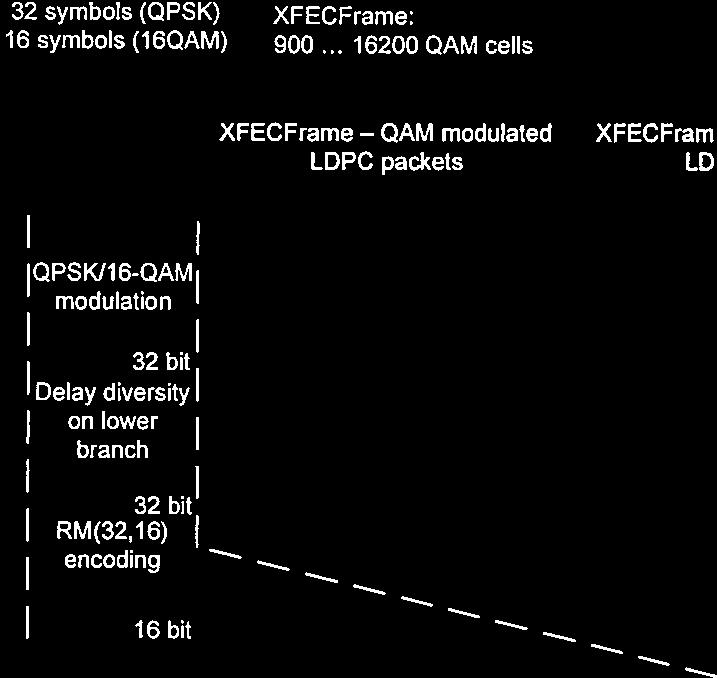
115 ITU-T Recommendation J.183 Time-division multiplexing of multiple MPEG-2 transport streams over cable television systems Summary This Recommendation describes a time-division multiplexing (TDM) format for transmission of multiple MPEG-2 transport streams using a simple implementation on cable television systems. The TDM frame encapsulates the MPEG-2 transport streams prior to transmission. The format features interoperability with the existing conventional satellite transmodulation format, which is designed based on the specification of Annex C/J.83 and Annex C/J.84 (SMATV system C(III)). This format may be applicable to other transmission systems. Information about the frame format should be transmitted in the network information table simultaneously, when this format is introduced into the existing digital cable television systems. It is needed for the set-top box to identify the digital channel containing multiple MPEG-2 transport streams. Source ITU-T Recommendation J.183 was prepared by ITU-T Study Group 9 ( ) and approved under the WTSA Resolution 1 procedure on 9 March ITU-T J.183 (03/2001) i
116 FOREWORD The International Telecommunication Union (ITU) is the United Nations specialized agency in the field of telecommunications. The ITU Telecommunication Standardization Sector (ITU-T) is a permanent organ of ITU. ITU-T is responsible for studying technical, operating and tariff questions and issuing Recommendations on them with a view to standardizing telecommunications on a worldwide basis. The World Telecommunication Standardization Assembly (WTSA), which meets every four years, establishes the topics for study by the ITU-T study groups which, in turn, produce Recommendations on these topics. The approval of ITU-T Recommendations is covered by the procedure laid down in WTSA Resolution 1. In some areas of information technology which fall within ITU-T's purview, the necessary standards are prepared on a collaborative basis with ISO and IEC. NOTE In this Recommendation, the expression "Administration" is used for conciseness to indicate both a telecommunication administration and a recognized operating agency. INTELLECTUAL PROPERTY RIGHTS ITU draws attention to the possibility that the practice or implementation of this Recommendation may involve the use of a claimed Intellectual Property Right. ITU takes no position concerning the evidence, validity or applicability of claimed Intellectual Property Rights, whether asserted by ITU members or others outside of the Recommendation development process. As of the date of approval of this Recommendation, ITU had not received notice of intellectual property, protected by patents, which may be required to implement this Recommendation. However, implementors are cautioned that this may not represent the latest information and are therefore strongly urged to consult the TSB patent database. ITU 2001 All rights reserved. No part of this publication may be reproduced or utilized in any form or by any means, electronic or mechanical, including photocopying and microfilm, without permission in writing from ITU. ii ITU-T J.183 (03/2001) 550
117 CONTENTS Page 1 Scope References Normative references Informative references Terms and definitions Abbreviations Multiple-TS transmission system Framing structure for multiple-ts transmission Physical interface and channel coding of the multiple-ts transmission system TSMF header structure Packet_header TSMF_sync Version_number Slot_information Identifiers_information Control information Relative TS number information... 6 Appendix I ITU-T J.183 (03/2001) iii
118 ITU-T Recommendation J.183 Time-division multiplexing of multiple MPEG-2 transport streams over cable television systems 1 Scope The scope of this Recommendation is the definition of a time-division multiplexing frame format to adapt the multiple MPEG-2 transport streams into the existing physical layer interface specified in Annex C/J.83. This format may be applicable to other transmission systems. The frame aims to multiplex transport streams without change except that some of the service information (SI) related to the network are replaced. By using this frame structure as an option to the conventional digital transmission equipment, multiple transport streams can be multiplexed as they are. The functionality of multiplexing transport streams into a single transport stream is not needed. Implementation of this frame format enables the cable television operator to pack multiple transport streams in a single channel. Also, the flexibility on operation of cable distribution network would be obtained if the integration of services could be achieved by the transport stream basis. This Recommendation provides the information needed by the designers and manufacturers of equipment (including receivers) for digital multi-programme signals distributed by cable networks. 2 References 2.1 Normative references The following ITU-T Recommendations and other references contain provisions which, through reference in this text, constitute provisions of this Recommendation. At the time of publication, the editions indicated were valid. All Recommendations and other references are subject to revision; users of this Recommendation are therefore encouraged to investigate the possibility of applying the most recent edition of the Recommendations and other references listed below. A list of the currently valid ITU-T Recommendations is regularly published. ITU-T H (2000) ISO/IEC :2000, Information technology Generic coding of moving pictures and associated audio information: systems. ITU-T J.83 (1997), Digital multi-programme systems for television, sound and data services for cable distribution. ITU-T J.84 (1997), Distribution of digital multi-programme signals for television, sound and data services thorough SMATV networks. ITU-T J.94 (1998), Service information for digital broadcasting in cable television systems. 2.2 Informative references JCTEA STD , Multiplexing System for Digital Cable Television. JCTEA STD , BS digital compliant Digital Cable Television Receiver. 552 ITU-T J.183 (03/2001) 1
119 3 Terms and definitions This Recommendation defines the following terms: 3.1 MPEG-2: Refers to ISO/IEC (All parts). Systems coding is defined in ITU-T H ISO/IEC Video coding is defined in ITU-T H.262 ISO/IEC Audio coding is defined in ISO/IEC and in ISO/IEC network: A collection of MPEG-2 transport stream multiplexes transmitted on a single delivery system, e.g., all digital channels on a specific cable system. 3.3 original_network_id: A label identifying the network_id of the originating delivery system. 3.4 programme: A concatenation of one or more events under the control of a broadcaster, e.g., news show, entertainment show. 3.5 physical interface: The interface on a physical layer equipment for transmission. 3.6 reserved_for_future_use: The term "reserved_for_future_use", when used in the clause defining the coded bitstream, indicates that the value may be used in the future defined extensions. All "reserved_for_future_use" bits shall be set to "1". 3.7 set-top box: A hardware box that contains digital signal demodulator, de-multiplexer, MPEG-2 decoder, other functionalities and interfaces related to digital signal reception and presentation of the distributed programme at the subscriber's site. 3.8 transport stream (TS): A TS is a data structure defined in ITU-T H ISO/IEC transport_stream_id (TS_id): A unique identifier of a TS within an original network. 4 Abbreviations This Recommendation uses the following abbreviations: bslbf bit string, left bit first CRC Cyclic Redundancy Check rpchof remainder polynomial coefficients, highest order first TS Transport Stream TSMF Transport Streams Multiplexing Frame uimsbf unsigned integer, most significant bit first 5 Multiple-TS transmission system The proposed framing structure for a multiple-ts transmission system meets the following requirements: a) Multiple MPEG-2 transport streams should be transmitted over a digital carrier in compliance with existing cable TV systems. b) All packets of all MPEG-2 transport streams should be transmitted without any packet loss. c) All transport streams received are in compliance with the specification of MPEG-2 systems. d) The system should make effective use of cable TV channel capacity. e) Delay time resulting from optional use of signal processing should not affect digital broadcasting services. f) The added cost of introduction of the optional facilities in a cable TV headend and the receiver should be low. 2 ITU-T J.183 (03/2001) 553
120 g) The system should support interoperability with conventional single transport stream transmission systems for cable distribution. 5.1 Framing structure for multiple-ts transmission The multiple-ts transmission system uses the frame structure shown in Table 1 to multiplex MPEG-2 transport streams (TSs). The frame is called the transport streams multiplexing frame (TSMF). The TS packets shall be assigned to slots in the TSMF. A slot is constituted from 188 bytes of the same size as a TS packet, and the TSMF consists of N slots. The TSMF has a TSMF_header in the first slot. In the TSMF_header, information about multiplexing and de-multiplexing is contained. By outputting this frame repeatedly, multiple TSs are transmitted. TSMF () { } Table 1/J.183 TSMF structure Syntax No. of bytes Description TSMF_header() 188 for (i = 1; i < N; i++){ } TS_packet[i] Physical interface and channel coding of the multiple-ts transmission system Except for the framing block, channel coding is identical to that of the single-ts transmission system (Figure 1) because the multiplexed signal by using the TSMF is a stream of TS packets. The technology and standards specified for the physical interface of a single-ts transmission system, for example, ITU-T J.83, can be applied. Multiple TSs Single TS (existing scheme) TS TS TS TS Framing Existing transmission scheme Common physical interface T Distribution over cable TV networks Figure 1/J.183 System configuration for single TS and multiple TSs transmission 5.3 TSMF header structure The TSMF_header should be comprised of 188-byte data. The first byte of 0x47 is for packet synchronization purpose, followed by 187 bytes of the following information: frame synchronization; MPEG-2 TS identification for each slot; and 554 ITU-T J.183 (03/2001) 3
121 others (e.g. version number, flag bit for emergency alert broadcasting). Each of the MPEG-2 TSs, multiplexed in the TSMF, is uniquely distinguished by the TS identification (TS_id) and original network identification (original_network_id). Instead of directly using the corresponding information between a slot number and TS_id/original_network_id, the relative TS number (relative_ts_number) is employed. The TS_id/original_network_id of a TS, which a TS_packet in a slot belongs to, is resolved in two stages: the first is translation of slot number to relative_ts_number, and the next is translation of relative_ts_number to TS_id/original_network_id. This method reduces the number of bits for the TS identification in the TSMF_header. The content of the TSMF_header is specified in Table 2 and below: TSMF_header() { } Table 2/J.183 TSMF_header Syntax No. of bits Description packet_header() 32 TSMF_sync version_number slot_information() 16 bslbf identifiers_information() 32 * M M = 2^m 1 control_information() relative_ts_information() m * (N 1) private_data 1424 V S 32 * M C m * (N 1) CRC NOTE 1 The semantic definition of the fields in the TSMF header is as follows: TSMF_sync: This is a 16-bit field. Its value shall be determined by the system. V S C bslbf 32 rpchof version_number: This V-bit field is the version number that indicates renewal of the area from the slot_information to the control_information in the TSMF_header. It shall be incremented by 1 when a change occurs. When it reaches maximum value, it wraps around to 0. private_data: This is a field whose syntax and semantics shall be defined by the system. CRC: CRC (cyclic redundancy check) is added to detect any errors. As defined in ITU-T H.222.0, the value of CRC has zero register output when 184 bytes of a TSMF_header, excluding the first 4 bytes, are input into the register of a decoder. NOTE 2 V + S = 8 * I 1, where V is the number of bits for version_number, S is the number of bits for slot_information, and I 1 is an integer. NOTE 3 C = 8 * I 2, where C is the number of bits for control_information, and I 2 is an integer. NOTE 4 N is the number of slots in the TSMF, or the total length of the frame. NOTE 5 M is the maximum number of transport streams multiplexed in the TSMF Packet_header The first 4 bytes of the TSMF_ header have a structure similar to the MPEG-2 TS packet header, as shown in Table 3. 4 ITU-T J.183 (03/2001) 555
122 packet_header() { } Table 3/J.183 Packet_header Syntax No. of bits Description sync_byte 8 bslbf '000' 3 bslbf TSMF_header_PID 13 uimsbf '0001' 4 bslbf continuity_counter 4 uimsbf NOTE The semantic definition of the fields in packet header is as follows: sync_byte: This is a fixed 8-bit field whose value is ' ' (0x47). TSMF_header_PID: This is a 13-bit field whose value is set to a unique value other than the PIDs of TS packets. The TSMF_header can be identified from other TS packets, as the value of TSMF_header_PID is unique. continuity_counter: The continuity_counter is a 4-bit field incrementing with each TSMF_header. When the value reaches '1111' (0x0f), it wraps around to TSMF_sync The TSMF_sync is used for frame synchronization. Using the TSMF_sync and the TSMF_header_PID together, frame synchronization is ensured. The value shall be defined by the system Version_number The version_number indicates renewal of the TSMF_header information. It shall be incremented each time the TSMF header is renewed. The receiver may decode the TSMF header information only when a change of information occurs. The use of version number and the area where information renewal is examined are optionally defined by the system Slot_information The slot_information (see Table 4) shall include the TSMF_format, and the indicator of the availability of each relative_ts_number, and so on. The TSMF_format may indicate the maximum number of TSs transmitted simultaneously and the number of slots in the TSMF. Each of the availability_for_relative_ts_number shall be transmitted sequentially in order of the relative_ts_number from 1 to M. Table 4/J.183 Slot_information Syntax No. of bits Description slot_information() { TSMF_format F bslbf for (i = 1; i <= M; i++) { M = 2^m 1 availability_for_relative_ts_number[i] 1 bslbf } reserved_for_future_use S-F-M } NOTE 1 F is the number of bits of TSMF_format. 556 ITU-T J.183 (03/2001) 5
123 NOTE 2 M is the maximum number of transport streams multiplexed in the TSMF. NOTE 3 S is the number of bits of slot_information. NOTE 4 Semantic definition of the fields in the slot information is as follows: TSMF_format: This is a V-bit field which indicates N and M. The value of N and M should be the same as defined in Annex C/J.94. availability_for_relative_ts_number[i]: This is a 1-bit field that represents availability of the TS labelled by relative_ts_number i Identifiers_information Table 5 shows the algorithm relating relative_ts_number and TS_id/original_network_id. TS_id/original_network_id shall be composed of 32-bit numbers and shall be arranged in order of the relative_ts_number from 1 to M. identifiers_information(){ Table 5/J.183 Identifiers_information Syntax No. of bits Description for (i = 1; i <= M; i++) { M = 2^m 1 } } TS_id[i] 16 uimsbf original_network_id[i] 16 uimsbf NOTE 1 The maximum number of TSs transmitted simultaneously, M, shall be indicated by the 'TSMF_format' as shown in Table 4. NOTE 2 The semantic definition of the fields in the identifiers information is as follows: TS_id[i]: This is a 16-bit field that represents TS_id of the TS labelled as relative_ts_number i. original_network_id[i]: This is a 16-bit field that represents original_network_id of the TS labelled as relative_ts_number i Control information The control information may be used to control set-top boxes, e.g. a flag for emergency alert broadcasting. The encoding format shall be defined by the system. The number of bits for the control information, "C", is defined in Table Relative TS number information The relative_ts_number for each TS_packet shall be transmitted sequentially in order of slot from 1 to (N 1) as shown in Table 6. The number of slots in TSMF, N, shall be defined by the system. 6 ITU-T J.183 (03/2001) 557
124 Table 6/J.183 Relative TS_number_information Syntax No. of bits Description relative_ts_information(){ for (i = 1; i < N; i++) { relative_ts_number[i] m uimsbf } } NOTE 1 M is 2^ m 1. NOTE 2 Semantic definition of the fields in the relative TS number information is as follows: relative_ts_number[i]: This is an m-bit field that represents the relative_ts_number of the i-th TS_packet. APPENDIX I Table I.1 shows parameters for the TSMF employed with the physical layer interface specified in Annex C/J.83. Table I.1/J.183 System parameters Parameter Notation Value Remarks The number of slots in the N 53 including TSMF_header TSMF, or the total length of the frame The maximum number of transport streams multiplexed in the TSMF M 15 TSMF_sync reserved 3 bits 0x1a86 13 bits version_number 3 bits (V = 3) slot_information 21 bits (S = 21) TSMF_type slot_allocation_type 1 bit frame_type a) 4 bits (F = 5) control_information receive_status 2 * M = 30 bits emergency_indicator 1 bit private_data 85 bytes a) The "frame_type" in the TSMF_type should be included in the cable delivery system descriptor of network information table (NIT) for the reception. The set-top box could identify whether each channel on cable network is with the TSMF or not. The values of N and M are identical to the definition in Annex C/J ITU-T J.183 (03/2001) 7
125 SERIES OF ITU-T RECOMMENDATIONS Series A Series B Series C Series D Series E Series F Series G Series H Series I Series J Series K Series L Series M Series N Series O Series P Series Q Series R Series S Series T Series U Series V Series X Series Y Series Z Organization of the work of ITU-T Means of expression: definitions, symbols, classification General telecommunication statistics General tariff principles Overall network operation, telephone service, service operation and human factors Non-telephone telecommunication services Transmission systems and media, digital systems and networks Audiovisual and multimedia systems Integrated services digital network Cable networks and transmission of television, sound programme and other multimedia signals Protection against interference Construction, installation and protection of cables and other elements of outside plant TMN and network maintenance: international transmission systems, telephone circuits, telegraphy, facsimile and leased circuits Maintenance: international sound programme and television transmission circuits Specifications of measuring equipment Telephone transmission quality, telephone installations, local line networks Switching and signalling Telegraph transmission Telegraph services terminal equipment Terminals for telematic services Telegraph switching Data communication over the telephone network Data networks and open system communications Global information infrastructure and Internet protocol aspects Languages and general software aspects for telecommunication systems 559 Geneva, 2001
126 560
127 INTERNATIONAL TELECOMMUNICATION UNION STUDY GROUP 9 TELECOMMUNICATION STANDARDIZATION SECTOR STUDY PERIOD TD 576 Rev.1 (GEN/9) English only Original: English Question(s): 1/9 Geneva, 8-12 September 2014 TD Source: Rapporteur for Q1/9 Title: Output Draft revised Recommendation J.183 " Time-division multiplexing of multiple MPEG-2 transport streams over cable television systems " for progressing Based on the COM9-C59 discussion, Q1/9 provides TD AAA, the draft revision of J.183 for progressing. Revision marks indicated in this document are developed in this meeting. Contact: Shigeyuki Sakazawa KDDI Corporation Japan Tel: Fax: sh-sakazawa@kddi.com Attention: This is not a publication made available to the public, but an internal ITU-T Document intended only for use by the Member States of ITU, by ITU-T Sector Members and Associates, and their respective staff and collaborators in their ITU related work. It shall not be made available to, and used by, any other persons or entities without the prior written consent of ITU-T. 561
128 - 2 - TD 576 Rev.1 (GEN/9) [DRAFT REVISED] ITU-T RECOMMENDATION J.183 ITU-T Recommendation J.183 Time-division multiplexing of multiple MPEG-2 transport streams over cable television systems 1 Scope The scope of this Recommendation is the definition of a time-division multiplexing frame format to adapt the multiple MPEG-2 transport streams, some of which exceeds the transmission rate per a single channel, into the existing physical layer interface specified in Annex C/J.83. This format may be applicable to other transmission systems. The frame aims to multiplex transport streams without change except that some of the service information (SI) related to the network are replaced. By using this frame structure as an option to the conventional digital transmission equipment, multiple transport streams can be multiplexed as they are. The functionality of multiplexing transport streams into a single transport stream is not needed. Also, the expansion of the frame format, being compliant with the first version of J.183 ( ), can provide the additional functionality for high speed transmission scheme by channel bonding technology. Implementation of this the first version of the frame format enables the cable television operator to pack multiple transport streams in a single channel. And the second version of this frame format can be additionally applied to high speed transport streams, such as UHDTV signals, to be multiplexed into multiple channels as well. In other words, the second version of J.183 maintains backward compatibility with the first one. {Editor s note: appropriate expression for first/second version should be considered.} Also, tthe flexibility on operation of cable distribution network would be obtained if the integration of services could be achieved by the transport stream basis. This Recommendation provides the information needed by the designers and manufacturers of equipment (including receivers) for digital multi-programme signals distributed by cable networks. 書式変更 : 蛍光ペン 2 References 2.1 Normative references The following ITU-T Recommendations and other references contain provisions which, through reference in this text, constitute provisions of this Recommendation. At the time of publication, the editions indicated were valid. All Recommendations and other references are subject to revision; users of this Recommendation are therefore encouraged to investigate the possibility of applying the most recent edition of the Recommendations and other references listed below. A list of the currently valid ITU-T Recommendations is regularly published. ITU-T H (2000) ISO/IEC :2000, Information technology Generic coding of moving pictures and associated audio information: systems. ITU-T J.83 (1997), Digital multi-programme systems for television, sound and data services for cable distribution. 562
129 - 3 - TD 576 Rev.1 (GEN/9) ITU-T J.84 (1997), Distribution of digital multi-programme signals for television, sound and data services thorough SMATV networks. ITU-T J.94 (1998), Service information for digital broadcasting in cable television systems. 2.2 Informative references JCTEA STD , Multiplexing System for Digital Cable Television. JCTEA STD , BS digital compliant Digital Cable Television Receiver. 563
130 - 4 - TD 576 Rev.1 (GEN/9) 3 Terms and definitions This Recommendation defines the following terms: 3.1 MPEG-2: Refers to ISO/IEC (All parts). Systems coding is defined in ITU-T H ISO/IEC Video coding is defined in ITU-T H.262 ISO/IEC Audio coding is defined in ISO/IEC and in ISO/IEC network: A collection of MPEG-2 transport stream multiplexes transmitted on a single delivery system, e.g., all digital channels on a specific cable system. 3.3 original_network_id: A label identifying the network_id of the originating delivery system. 3.4 programme: A concatenation of one or more events under the control of a broadcaster, e.g., news show, entertainment show. 3.5 physical interface: The interface on a physical layer equipment for transmission. 3.6 reserved_for_future_use: The term "reserved_for_future_use", when used in the clause defining the coded bitstream, indicates that the value may be used in the future defined extensions. All "reserved_for_future_use" bits shall be set to "1". 3.7 set-top box: A hardware box that contains digital signal demodulator, de-multiplexer, MPEG-2 decoder, other functionalities and interfaces related to digital signal reception and presentation of the distributed programme at the subscriber's site. 3.8 transport stream (TS): A TS is a data structure defined in ITU-T H ISO/IEC transport_stream_id (TS_id): A unique identifier of a TS within an original network. 4 Abbreviations This Recommendation uses the following abbreviations: bslbf bit string, left bit first CRC Cyclic Redundancy Check rpchof remainder polynomial coefficients, highest order first TS Transport Stream TSMF Transport Streams Multiplexing Frame uimsbf unsigned integer, most significant bit first 5 Multiple-TS transmission system The proposed framing structure for a multiple-ts transmission system meets the following requirements: a) Multiple MPEG-2 transport streams should be transmitted over a digital carrier in compliance with existing cable TV systems. b) All packets of all MPEG-2 transport streams should be transmitted without any packet loss. c) All transport streams received are in compliance with the specification of MPEG-2 systems. d) The system should make effective use of cable TV channel capacity. 564
131 - 5 - TD 576 Rev.1 (GEN/9) e) Delay time resulting from optional use of signal processing should not affect digital broadcasting services. f) The added cost of introduction of the optional facilities in a cable TV headend and the receiver should be low. 565
132 - 6 - TD 576 Rev.1 (GEN/9) g) The system should support interoperability with conventional single transport stream transmission systems for cable distribution. 5.1 Framing structure for multiple-ts transmission The multiple-ts transmission system uses the frame structure shown in Table 1 to multiplex MPEG-2 transport streams (TSs). The frame is called the transport streams multiplexing frame (TSMF). The TS packets shall be assigned to slots in the TSMF. A slot is constituted from 188 bytes of the same size as a TS packet, and the TSMF consists of N slots. The TSMF has a TSMF_header in the first slot. In the TSMF_header, information about multiplexing and demultiplexing is contained. By outputting this frame repeatedly, multiple TSs are transmitted. Table 1/J.183 TSMF structure Syntax No. of bytes Description TSMF () { TSMF_header() 188 for (i = 1; i < N; i++){ TS_packet[i] 188 } } 5.2 Physical interface and channel coding of the multiple-ts transmission system Except for the framing block, channel coding is identical to that of the single-ts transmission system (Figure 1) because the multiplexed signal by using the TSMF is a stream of TS packets. The technology and standards specified for the physical interface of a single-ts transmission system, for example, ITU-T J.83, can be applied. Multiple TSs Single TS (existing scheme) TS TS TS TS Framing Existing transmission scheme Common physical interface T Distribution over cable TV networks Figure 1/J.183 System configuration for single TS and multiple TSs transmission 5.3 TSMF header structure The TSMF_header should be comprised of 188-byte data. The first byte of 0x47 is for packet synchronization purpose, followed by 187 bytes of the following information: frame synchronization; 566
133 - 7 - TD 576 Rev.1 (GEN/9) MPEG-2 TS identification for each slot; and 567
134 - 8 - TD 576 Rev.1 (GEN/9) others (e.g. version number, flag bit for emergency alert broadcasting). Each of the MPEG-2 TSs, multiplexed in the TSMF, is uniquely distinguished by the TS identification (TS_id) and original network identification (original_network_id). Instead of directly using the corresponding information between a slot number and TS_id/original_network_id, the relative TS number (relative_ts_number) is employed. The TS_id/original_network_id of a TS, which a TS_packet in a slot belongs to, is resolved in two stages: the first is translation of slot number to relative_ts_number, and the next is translation of relative_ts_number to TS_id/original_network_id. This method reduces the number of bits for the TS identification in the TSMF_header. The content of the TSMF_header is specified in Table 2 and below: Table 2/J.183 TSMF_header Syntax No. of bits Description TSMF_header() { packet_header() 32 TSMF_sync 16 bslbf version_number V slot_information() S identifiers_information() 32 * M M = 2^m 1 control_information() C bslbf relative_ts_information() m * (N 1) private_data 1424 V S 32 * M C m * (N 1) CRC 32 rpchof } NOTE 1 The semantic definition of the fields in the TSMF header is as follows: TSMF_sync: This is a 16-bit field. Its value shall be determined by the system. version_number: This V-bit field is the version number that indicates renewal of the area from the slot_information to the control_information in the TSMF_header. It shall be incremented by 1 when a change occurs. When it reaches maximum value, it wraps around to 0. private_data: This is a field whose syntax and semantics shall be defined by the system. CRC: CRC (cyclic redundancy check) is added to detect any errors. As defined in ITU-T H.222.0, the value of CRC has zero register output when 184 bytes of a TSMF_header, excluding the first 4 bytes, are input into the register of a decoder. NOTE 2 V + S = 8 * I 1, where V is the number of bits for version_number, S is the number of bits for slot_information, and I 1 is an integer. NOTE 3 C = 8 * I 2, where C is the number of bits for control_information, and I 2 is an integer. NOTE 4 N is the number of slots in the TSMF, or the total length of the frame. NOTE 5 M is the maximum number of transport streams multiplexed in the TSMF Packet_header The first 4 bytes of the TSMF_ header have a structure similar to the MPEG-2 TS packet header, as shown in Table
135 - 9 - TD 576 Rev.1 (GEN/9) packet_header() { } Table 3/J.183 Packet_header Syntax No. of bits Description sync_byte 8 bslbf '000' 3 bslbf TSMF_header_PID 13 uimsbf '0001' 4 bslbf continuity_counter 4 uimsbf NOTE The semantic definition of the fields in packet header is as follows: sync_byte: This is a fixed 8-bit field whose value is ' ' (0x47). TSMF_header_PID: This is a 13-bit field whose value is set to a unique value other than the PIDs of TS packets. The TSMF_header can be identified from other TS packets, as the value of TSMF_header_PID is unique. continuity_counter: The continuity_counter is a 4-bit field incrementing with each TSMF_header. When the value reaches '1111' (0x0f), it wraps around to TSMF_sync The TSMF_sync is used for frame synchronization. Using the TSMF_sync and the TSMF_header_PID together, frame synchronization is ensured. The value shall be defined by the system Version_number The version_number indicates renewal of the TSMF_header information. It shall be incremented each time the TSMF header is renewed. The receiver may decode the TSMF header information only when a change of information occurs. The use of version number and the area where information renewal is examined are optionally defined by the system Slot_information The slot_information (see Table 4) shall include the TSMF_format, and the indicator of the availability of each relative_ts_number, and so on. The TSMF_format may indicate the maximum number of TSs transmitted simultaneously and the number of slots in the TSMF. Each of the availability_for_relative_ts_number shall be transmitted sequentially in order of the relative_ts_number from 1 to M. Table 4/J.183 Slot_information Syntax No. of bits Description slot_information() { TSMF_format F bslbf for (i = 1; i <= M; i++) { M = 2^m 1 availability_for_relative_ts_number[i] 1 bslbf } 569
136 TD 576 Rev.1 (GEN/9) } reserved_for_future_use NOTE 1 F is the number of bits of TSMF_format. S-F-M 570
137 TD 576 Rev.1 (GEN/9) NOTE 2 M is the maximum number of transport streams multiplexed in the TSMF. NOTE 3 S is the number of bits of slot_information. NOTE 4 Semantic definition of the fields in the slot information is as follows: TSMF_format: This is a V-bit field which indicates N and M. The value of N and M should be the same as defined in Annex C/J.94. availability_for_relative_ts_number[i]: This is a 1-bit field that represents availability of the TS labelled by relative_ts_number i Identifiers_information Table 5 shows the algorithm relating relative_ts_number and TS_id/original_network_id. TS_id/original_network_id shall be composed of 32-bit numbers and shall be arranged in order of the relative_ts_number from 1 to M. Table 5/J.183 Identifiers_information Syntax No. of bits Description identifiers_information(){ for (i = 1; i <= M; i++) { M = 2^m 1 TS_id[i] 16 uimsbf original_network_id[i] 16 uimsbf } } NOTE 1 The maximum number of TSs transmitted simultaneously, M, shall be indicated by the 'TSMF_format' as shown in Table 4. NOTE 2 The semantic definition of the fields in the identifiers information is as follows: TS_id[i]: This is a 16-bit field that represents TS_id of the TS labelled as relative_ts_number i. original_network_id[i]: This is a 16-bit field that represents original_network_id of the TS labelled as relative_ts_number i Control information The control information may be used to control set-top boxes, e.g. a flag for emergency alert broadcasting. The encoding format shall be defined by the system. The number of bits for the control information, "C", is defined in Table Relative TS number information The relative_ts_number for each TS_packet shall be transmitted sequentially in order of slot from 1 to (N 1) as shown in Table 6. The number of slots in TSMF, N, shall be defined by the system. 571
138 TD 576 Rev.1 (GEN/9) relative_ts_information(){ for (i = 1; i < N; i++) { } } Table 6/J.183 Relative TS_number_information Syntax No. of bits Description relative_ts_number[i] m uimsbf NOTE 1 M is 2^ m 1. NOTE 2 Semantic definition of the fields in the relative TS number information is as follows: relative_ts_number[i]: This is an m-bit field that represents the relative_ts_number of the i-th TS_packet. 572
139 TD 576 Rev.1 (GEN/9) Annex A for digital multi-programme System A (For further study) {Editor s note: provide definition of System A and System B.} 書式変更 : 蛍光ペン Annex B for digital multi-programme System B (For further study) C.1 Introduction Annex C Extended format of TSMF for System C of J.83 (This annex forms an integral part of this Recommendation) This annex describes the extension format of existing TSMF structure in order to adapt a large capacity of MPEG-2 transport streams, such as an UHDTV signals including a large capacity of transport stream, to be divided into the multiple channel physical layer interfaces specified in Annex C/J.83. The extendedextended TSMF is designed for channel bonding technology. It is backward compatible with the first version of TSMF, J.183 ( ). This technology will support cable TV transmission system to distribute relatively large sized contents with multiple carriers while conventional system having HDTV channels in the same physical layer specification. C.2 Concept Figure C.1 overviews the channel bonding technology. The large capacity of MPEG-2 TS is divided at the cable TV headend and multiplexed into time division multiplexing (TDM) frames that are described as "Super Frames" in the following section. Each of the frames is transmitted by a 64 QAM or 256 QAM signal. Each of the QAM channels can be allocated to any frequency. The signal of each channel is separately demodulated and all of the demodulated signals are restored to the original MPEG-2 TS of UHDTV at a receiver. The channels carrying UHDTV service and those for existing broadcasting services are confirmed not to disturb each other. As 256 QAM offers transmission capacity larger than 64 QAM, the former is preferable to transmit UHDTV signals. However, 256 QAM is less robust against any kind of noise and distortion than 64 QAM. 573
140 TD 576 Rev.1 (GEN/9) Cable TV operato UHDTV HDTV Divide and multiplexer Mod. 256 QAM 256 QAM 256 QAM 256 QAM 64 QAM Cable television network Subscriber Demod. 256 QAM 256 QAM 256 QAM 256 QAM 64 QAM Combine UHDTV HDTV 256 QAM 64 QAM Figure C.1 Overview of channel bonding technology. Frequency 574
141 TD 576 Rev.1 (GEN/9) Figure C.2 shows an example of the combination of one 64 QAM and four 256 QAM channels used for a single UHDTV transmission. In this figure, a UHDTV signal occupies four 256 QAM channels and a part of 64 QAM channel. It is noted that another program such as a HDTV may be transmitted with the use of the remained capacity of the 64 QAM channel. Any combination of QAM scheme among the relevant multi carriers group should be allowed for cable TV operation. Since the bitrates transmitted by 64 and 256 QAMs are different, e-tsmf is required for bonding channels with different bitrates. UHDTV Low CNR e.g.., HDTV Noise Frequency 256 QAM 256 QAM 256 QAM 256 QAM 64 QAM Figure C.2 Multiple channels used for UHDTV transmission. Figure C.3 shows an example of a TS transmitted by one 64 QAM and two 256 QAM signals by using extendedextended TSMF format. Channel coding is identical to that of the single-ts transmission system because the stream divided for multiple channels by using the Extended TSMF is a stream of TS packets. MPEG-2 TS 変更されたフィールドコード Stream divided for multiple channels Extended TSMF Extended TSMF Extended TSMF TDM output sync inv.&randomized RS coding conv. interleaver byte to symbol differential encoding Roll-off filtering 64 QAM RF physical I/F J.83 interface for single TS sync inv.&randomized RS coding conv. interleaver byte to symbol differential encoding Roll-off filtering 256 QAM RF physical I/F J.83 interface for single TS sync inv.&randomized RS coding conv. interleaver byte to symbol differential encoding Roll-off filtering 256 QAM RF physical I/F J.83 interface for single TS Figure C.3 Example of a TS carried by one 64 QAM and two 256 QAM signals by using extendedextended TSMF format. 575
142 C.3 Super frame TD 576 Rev.1 (GEN/9) Figure C.4 outlines the structure of the super frame. The number of TSMFs in a super frame is determined to make the periods of super frames identical regardless of the modulation format. 64 QAM TSMF_ header 52 slots TSMF_ header TSMF_ header 52 slots 52 slots super frame 256 QAM TSMF_ header 52 slots TSMF_ header 52 slots TSMF_ header 52 slots TSMF_ header 52 slots Time Figure C.4 Structure of super-frame for 64 QAM and 256 QAM. A super frame for a 64 QAM has three TSMFs and that for a 256 QAM has four TSMFs according to the bit-rate ratio. The modulation scheme of either channel, 64 QAM or 256 QAM, is determined depending on the transmission characteristics of the channel. At the receiver, the arrival time of transmitted signals may differ depending on the propagation delay in each channel. A receiver has to temporally align all relevant signals demodulated from received carriers. The TSMF_header of the first TSMF in every super frame is utilized as a marker to synchronize received signals. In order to apply the TSMF structure for channel bonding technology, we define some of the additional parameters in the private data of TSMF_header in J
143 C.4 Extended TSMF TD 576 Rev.1 (GEN/9) In order to define the extendedextended TSMF for channel bonding functionality, additional parameters are specified within the private data of TSMF_header as shown in Table C.1: Table C.1 TSMF and ExtendedExtended TSMF header TSMF_header Extended TSMF_header No.of bits Description TSMF_header() { Extended_TSMF_header() { packet_header() TSMF_sync version_number slot_information() identifiers_information() control_information() relative_ts_number_information() private_data The field private data is replaced by the field specified as shown in the right column as the second version. Before implementation, users should confirm that conventional receiver is not affected by the additional definition in this field. It was defined as private data field in the first version( ). CRC } } auxiliary code information group_id number_of_carriers carrier_sequence number_of_frames frame_position reserved_for_future_use the same as Table 3/J.183 the same as Table 2/J.183 the same as Table 2/J.183 the same as Table 4/J.183 the same as Table 5/J.183 the same as Table 2/J.183 the same as Table 6/J.183 AC See NOTE2 the same as Table 2/J.183 NOTE1 The definition of specific fields in the Extended TSMF header is as follows: bslbf uimsbf uimsbf uimsbf uimsbf uimsbf auxiliary code information: This code information is used to provide auxiliary information for cable TV subscribers, such as, earthquake early warning message in the specific region. The number of bits for auxiliary code information, "AC", and its coding format shall be defined by the system. group_id: This is a 8-bit field which represents a unique identifier of a group corresponding to bonding channels. number_of_carriers: This is a 8-bit field which describes the number of carriers for channel bonding in the same group_id. carrier_sequence: This is a 8-bit field which indicates the sequence number for channel bonding among carriers with the same group id. number_of_frames: This is a 4-bit field which represents the number of Extended TSMF included in the super frame. (ex. 0x03 for 64 QAM, 0x04 for 256 QAM in J.83 Annex C) frame_position: This is a 4-bit field which represents the sequence number of multiple Extended TSMFs in the super frame. 577
144 TD 576 Rev.1 (GEN/9) NOTE2 The value is {(No. of bits in private_data in Table 2/J.183) AC 578
145 TD 576 Rev.1 (GEN/9) APPENDIX I Table I.1 shows parameters for the TSMF employed with the physical layer interface specified in Annex C/J.83. Table I.1/J.183 System parameters Parameter Notation Value Remarks The number of slots in the N 53 including TSMF_header TSMF, or the total length of the frame The maximum number of transport streams multiplexed in the TSMF M 15 TSMF_sync reserved 3 bits 0x1a86 13 bits version_number 3 bits (V = 3) slot_information 21 bits (S = 21) TSMF_type slot_allocation_type 1 bit frame_type a) 4 bits (F = 5) control_information receive_status 2 * M = 30 bits emergency_indicator 1 bit private_data 85 bytes a) The "frame_type" in the TSMF_type should be included in the cable delivery system descriptor of network information table (NIT) for the reception. The set-top box could identify whether each channel on cable network is with the TSMF or not. The values of N and M are identical to the definition in Annex C/J
 (Japan Broadcasting Corporation) Title: Proposed new work item for high speed transmission scheme by channel bonding technology for UHDTV distribution")
146 INTERNATIONAL TELECOMMUNICATION UNION TELECOMMUNICATION STANDARDIZATION SECTOR STUDY PERIOD COM 9 C 59 E August 2014 English only Original: English Question(s): 1/9 STUDY GROUP 9 CONTRIBUTION 59 Source: Nippon Hoso Kyokai (NHK) (Japan Broadcasting Corporation) Title: Proposed new work item for high speed transmission scheme by channel bonding technology for UHDTV distribution on cable TV networks List of Authors: HAKAMADA Yoshitaka, KURAKAKE Takuya, NAKAMURA Naoyoshi, and OYAMADA Kimiyuki Introduction Recently, development and standardization of the systems for UHDTV is accelerating. For example, in ITU-R Study Group 4, transmission systems for UHDTV satellite broadcasting is under study as described in Annex 9 to Document 4B/162 Working document towards a preliminary draft new Recommendation ITU-R BO.[UHDTV_Transmission] - Transmission system for UHDTV satellite broadcasting. And Japan has a plan for test broadcasting of UHDTV (the system specified in Recommendation ITU-R BT. 2020) via satellite in NHK has developed a cable transmission scheme for UHDTV distribution and proposed it to the Japan Cable Television Engineering Association (JCTEA) which is one of the recognized SDOs according to Recommendations ITU-T A.5. It allows a high speed downstream transmission which exceeds the physical bit rate capacity per cable TV channel by channel bonding technology. The channel bonding is achieved by extension of Time Division Multiplexing (TDM) frame format of MPEG-2 transport streams defined in Recommendation J.183 and physical layer specification for secondly distribution defined in Recommendation J.83, and thus the system maintains backward compatibility with Recommendation J.183 and can be commonly used in the transport layer regardless of the format of the physical layer. Contact: Contact: NAKAMURA Naoyoshi Nippon Hoso Kyokai (NHK) Japan HAKAMADA Yoshitaka Nippon Hoso Kyokai (NHK) Japan Tel: Fax: nakamura.n-es<at>nhk.or.jp Tel: Fax: hakamada.y-hk<at>nhk.or.jp Attention: This is not a publication made available to the public, but an internal ITU-T Document intended only for use by the Member States of ITU, by ITU-T Sector Members and Associates, and their respective staff and collaborators in their ITU related work. It shall not be made available to, and used by, any other persons or entities without the prior written consent of ITU-T. 580
147 - 2 - COM 9 C 59 E Considering its importance of the study in time on UHDTV distribution over cable networks in ITU-T, Study Group 9 should start to study a new work item for seeking high speed transmission scheme, which is easy to implement in operating cable TV facilities. Two attachments are provided in this document for consideration to the initiation of the new work. Attachment 1 contains working document with an overview of the system for seeking discussion towards revision of Recommendation or development of a draft new Recommendation. Attachment 2 describes the results of performance evaluation tests of our proposed cable TV transmission system for UHDTV distribution. Related ITU-T Recommendations and documents/publications to the work described in Attachment 1 and 2 are listed below for information. ITU-T Recommendations [1] Recommendation ITU-T H (06/2012) ISO/IEC :2000, Information technology Generic coding of moving pictures and associated audio information: systems. [2] Recommendation ITU-T J.83 (12/2007), Digital multi-programme systems for television, sound and data services for cable distribution. [3] Recommendation ITU-T J.94 (11/2008), Service information for digital broadcasting in cable television systems [4] Recommendation ITU-T J.183 (03/2001), Time-division multiplexing of multiple MPEG-2 transport streams over cable television systems Other documents and publications [5] "Proposed working document towards a preliminary draft new recommendation" ITU-R BO.[UHDTV_TRANSMISSION], Document 4B/153, (Jun. 2014) [6] "An UHDTV Cable Television Distribution in Combinations of Multiple 64 and 256 QAM Channels," IEEE ICCE2013 vol.2, pp , (Jan. 2013) [7] "UHDTV (8K) Distribution Technology and Field Trial on Cable Television Networks", ITE Trans. on MTA, 2, 1, pp.2-7, (Jan. 2014) [8] "Action for installation of UHDTV in Japan," ITU-R WP6C workshop, (Mar. 2014), [9] "8K Super Hi-vision distribution technology for cable TV networks"(may, 2014) 581

148 - 3 - COM 9 C 59 E ATTACHMENT 1 WORKING DOCUMENT TOWARDS revision of existing recommendation or development of a preliminary draft new Recommendation 1 Background As shown in the document (4B/153) of ITU-R SG4, The UHDTV satellite broadcasting system, which has been developed in Japan, provides transmission capacity about 100 Mbps through a 34.5 MHz satellite transponder using 16 APSK with an inner coding rate 7/9 and achieves a 99.5% service availability. Our proposal is based on research activity considering that a cable TV channel is having difficulty of carrying an UHDTV broadcasting signal which is planned to be distributed via satellite in Scope The scope of Attachment 1 is an introduction of an extended format of J.183 time-division multiplexing frame (TSMF 1 ) to adapt a large capacity of MPEG-2 transport stream, such as an UHDTV, to be divided into the multiple channel physical layer interfaces specified in Annex C/J.83. This format may be applicable to other transmission systems. 3 Overview of UHDTV distribution by using multiple channels Figure 1 overviews our developed channel bonding technology. The large capacity of MPEG-2 TS is divided at the cable TV headend and multiplexed into time division multiplexing (TDM) frames that are described as "Super Frames" in the following Section. Fig. 1 Overview of channel bonding technology. 1 TSMF (Transport Stream Multiplexing Frame) is defined in recommendation J
149 - 4 - COM 9 C 59 E Each of the frames is transmitted by a 64 QAM or 256 QAM signal. Each of the QAM channels can be allocated to any frequency. The signal of each channel is separately demodulated and all of the demodulated signals are restored to the original MPEG-2 TS of UHDTV at a receiver. UHDTV distribution has to coexist with conventional FDM based digital broadcasting distribution on cable television networks. The modulation schemes, 64 and 256 QAM, that the proposed method utilizes, are already standardized for cable transmission. Then channels carrying UHDTV service and those for existing broadcasting services are confirmed not to disturb each other. As 256 QAM offers transmission capacity larger than 64 QAM, the former is preferable to transmit UHDTV signals. However, 256 QAM is less robust against any kind of noise and distortion than 64 QAM. In most cable facilities, transmission characteristics on channels are different and some channels may have a low carrier-to-noise ratio (CNR). They can carry 64 QAM signals, but cannot carry 256 QAM signals. Since the proposed method utilizes both of 64 and 256 QAMs, it makes efficient use of cable channels. UHDTV Low CNR e.g.., HDTV Noise Frequency 256 QAM 256 QAM 256 QAM 256 QAM 64 QAM Fig. 2 Multiple channels used for UHDTV transmission. Fig. 2 shows an example of the combination of one 64 QAM and four 256 QAM channels used for a single UHDTV transmission. In this figure, a UHDTV signal occupies four 256 QAM channels and a part of 64 QAM channel. It is noted that another program such as a HDTV may be transmitted with the use of the remained capacity of the 64 QAM channel. The bitrates transmitted by 64 and 256 QAMs are different. This causes a problem how the bonding channels of different bitrates. To restore the UHDTV signal from data streams of different bitrates, we introduce the Super Frame, which is an large frame containing multiple TSMFs, described in the following section. 583
150 - 5 - COM 9 C 59 E Fig.3 shows an example of a TS transmitted by one 64 QAM and two 256 QAM signals by using extended TSMF format. Channel coding is identical to that of the single-ts transmission system because the stream divided for multiple channels by using the Extended TSMF is a stream of TS packets. The specification for the physical interface of a single-ts transmission system, for example, ITU-T J.83, can be applied as J.183(TSMF). The syntax of Extended TSMF is also described in the following section. MPEG-2 TS Stream divided for multiple channels Extended TSMF Extended TSMF Extended TSMF TDM output sync inv.&randomized RS coding conv. interleaver byte to symbol differential encoding Roll-off filtering 64 QAM RF physical I/F J.83 interface for single TS sync inv.&randomized RS coding conv. interleaver byte to symbol differential encoding Roll-off filtering 256 QAM RF physical I/F J.83 interface for single TS sync inv.&randomized RS coding conv. interleaver byte to symbol differential encoding Roll-off filtering 256 QAM RF physical I/F J.83 interface for single TS Fig. 3 Example of a TS carried by one 64 QAM and two 256 QAM signals by using extended TSMF format. 584

151 - 6 - COM 9 C 59 E 4 Proposal for Super Frames At the cable TV headend, the implementation of framing structure of the transport streams multiplexing frames (TSMF) of ITU-T J.183 enables cable TV operators to encapsulate multiple MPEG-2 TSs into a single stream independently. TSMF adapts the stream into the physical layer interface of existing cable TV modulator. Fig. 4 Framing structure of TSMF. One of the examples of TSMF (see Appendix I of J.183) is composed of the 53 slots shown in Fig. 4. Each slot is 188 bytes long, which is the same length as a MPEG-2 TS packet. The information identifying bundled MPEG-2 TS streams and other additional information are stored in the TSMF_header located in the first slot of TSMF. The maximum number of MPEG-2 TSs multiplexed in the TSMF is 15. Since the bitrate for 64 QAM is different from that for 256 QAM, the period to transmit a TSMF frame differs for 64 QAM and 256 QAM, which is 2.73 msec for the former and 2.05 msec for the latter since the symbol rate is Mbaud when applied in J.83 Annex C. Therefore, it is necessary to synchronize frames between demodulated signals at the receiver in combinations of multiple 64 and 256 QAM channels. We propose a novel super frame consisting of multiple TSMFs to use channel bonding technology in combinations of multiple 64 and 256 QAM channels. 585
152 - 7 - COM 9 C 59 E Fig. 5 outlines the structure of the super frame. The number of TSMFs in a super frame is determined to make the periods of super frames identical regardless of the modulation format. 64 QAM TSMF_ header 52 slots TSMF_ header TSMF_ header 52 slots 52 slots super frame 256 QAM TSMF_ header 52 slots TSMF_ header 52 slots Fig. 5 Structure of super-frame for 64 QAM and 256 QAM. A super frame for a 64 QAM has three TSMFs and that for a 256 QAM has four TSMFs according to the bit-rate ratio. The modulation scheme of either channel, 64 QAM or 256 QAM, is determined depending on the transmission characteristics of the channel. At the receiver, the arrival time of transmitted signals may differ depending on the propagation delay in each channel. A receiver has to temporally align all relevant signals demodulated from received carriers. The TSMF_header of the first TSMF in every super frame is utilized as a marker to synchronize received signals. The maximum acceptable delay difference between channels is designed so that it is equal to the minimum period of super frames, 8.2 msec, which corresponds to the duration of three TSMF frames for 64 QAM and that of four TSMF frames for 256 QAM. After all signals have been aligned, the receiver restores the split signals to the original MPEG-2 TS of UHDTV. In order to apply the TSMF structure for channel bonding technology, we define some of the additional parameters in the private_data of TSMF_header in J.183. TSMF_ header 52 slots TSMF_ header 52 slots Time 586
153 - 8 - COM 9 C 59 E For channel bonding functionality, the following parameters (T.B.D.) should be newly defined to have an extension of existing TSMF_header as shown in Table 1: Table 1 comparison of frame header between J.183 and the extension TSMF_header (J.183) Extended TSMF_header (T.B.D.) TSMF_header() { * the same as on the left packet_header() * TSMF_sync * version_number * slot_information() * identifiers_information() * control_information() * relative_ts_information() * private_data group_id number_of_carriers carrier_sequence number_of_frames frame_position CRC * } group_id: a unique identifier of a group corresponding to bonding channels. number_of_carriers: the number of carriers for channel bonding in the same group_id. carrier_sequence: the sequence number of carriers which contain Extended TSMF for channel bonding to restore original TSs number_of_frames: the number of Extended TSMF in which the super frame contains in the carrier. (ex. 0x03 for 64 QAM, 0x04 for 256 QAM in J.83 Annex C) frame_position: the sequence number of Extended TSMF in the super frame 587
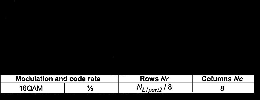
154 - 9 - COM 9 C 59 E 5 Channel bonding cable delivery system descriptor Additional descriptor, which will be located in NIT (Network Information Table), should be defined for receivers to identify the physical layer specification of channel bonding in cable TV network. Table 2 is a proposal of channel bonding cable delivery system descriptor. Table 2 -channel bonding cable delivery system descriptor (T.B.D.) Syntax No. of bits Identifier channel_bonding_cable_delivery_system_descriptor(){ descriptor_tag 8 uimsbf descriptor_length 8 uimsbf for(i=0;i<n;i++){ frequency 32 bslbf reserved_for_future_use 8 frame_type 4 uimsbf FEC_outer 4 bslbf modulation 8 bslbf symbol_rate 28 bslbf FEC_inner 4 bslbf } group_id 8 bslbf } 588
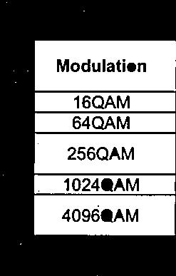
155 COM 9 C 59 E Semantics for channel bonding cable delivery system descriptor Below are the semantics extracted from Cable delivery system descriptor in J.94 Annex C. The frame type is to be revised for use in channel bonding cable TV descriptor. Table C.9/J.94 Frame type (To be revised) frame_type bit 3210 Description 0000 Reserved for future use 0001 (N, M) = (53, 15) a) a) 0010 The waveform is limited for channel bonding use to 1110 Reserved for future use 1111 None indicates that the waveform does not use TSMF The frame type (N, M) is (53,15) for Annex C. It might be determined for other transmission systems. FEC_outer: The FEC_outer is a 4-bit field specifying the outer Forward Error Correction (FEC) scheme used according to Table C.10. Table C.10/J.94 Outer FEC scheme FEC_outer bit 3210 Description 0000 Not defined 0001 No outer FEC coding 0010 RS(204/188) 0011 to 1111 Reserved for future use modulation: This is an 8-bit field. It specifies the modulation scheme used on a cable delivery system according to Table C.11. Table C.11/J.94 Modulation scheme for cable Modulation (hex) 0x00 0x01 0x02 0x03 0x04 0x05 0x06 to 0xFF Description Not defined 16-QAM 32-QAM 64-QAM 128-QAM 256-QAM Reserved for future use 589
156 COM 9 C 59 E symbol_rate: The symbol_rate is a 28-bit field giving the 4-bit BCD values specifying 7 characters of the symbol_rate in Msymbol/s where the decimal point occurs after the third character (e.g ). FEC_inner: The FEC_inner is a 4-bit field specifying the inner FEC scheme used according to Table C.12. Table C.12/J.94 Inner FEC scheme FEC_inner bit 3210 Description 0000 Not defined /2 conv. code rate /3 conv. code rate /4 conv. code rate /6 conv. code rate /8 conv. code rate 1111 No conv. Coding 0110 to 1110 Reserved for future use 590
157 COM 9 C 59 E ATTACHMENT 2 Performance Evaluation of the proposed channel bonding transmission system for UHDTV distribution 1 Experimental setup In order to find out how well our proposed method of transmission works, we evaluated the bit error rate (BER) and the functionality of multiple-channel bonding with our prototype. As shown in Fig. 6, a Mbps MPEG-2 TS is transmitted with five channels, consisting of a 64 QAM and four 256 QAMs. Headend 256 QAM Mod. (ch A) UHDTV MPEG-2 TS Divider Multiplexer 256 QAM Mod. (ch B) 256 QAM Mod. (ch C) 256 QAM Mod. (ch D) 64 QAM Mod. (ch E) Delay AWGN Tuner (ch A) Tuner (ch B) Tuner (ch C) Tuner (ch D) Tuner (ch E) Cable television network Receiver 256 QAM demod. 256 QAM demod. 256 QAM demod. 256 QAM demod. 64 QAM demod. Synchronization and combination Fig. 6 Experimental setup(indoor test). UHDTV MPEG-2 TS BER tester 591
 was added to all the channels. Fig. 7 is a photograph of the experimental setup for UHDTV transmission. Table 3 Parameters of Transmitted Signals.")
158 COM 9 C 59 E Table 3 summarizes the parameters of the transmitted signals. The input power at each tuner of the prototype receiver is 43.7 dbm. Additive white Gaussian noise (AWGN) was added to all the channels. Fig. 7 is a photograph of the experimental setup for UHDTV transmission. Table 3 Parameters of Transmitted Signals. MPEG-2 TS rate Mbps Video coding for UHDTV(8K) MPEG-4 AVC / H.264 Audio coding MPEG-2 AAC Bandwidth per channel 6 MHz Symbol rate Mbaud Bit rate per channel w/o parity bits for FEC 256 QAM : Mbps 64 QAM : Mbps No. of channels Four channels with 256 QAM and a channel with 64 QAM Center frequencies (MHz) 256 QAM: 267 MHz, 273 MHz 279 MHz and 285 MHz, 64 QAM: 291 MHz Fig. 7 Setup for UHDTV transmission. 592
159 2 BER performance COM 9 C 59 E The theoretical BER of 2 n QAM with rotational symmetry and gray coding is calculated as: n 2 n 1 2 BER erfc, (1) n 2 n 2 2 where n is the number of bits per symbol, δ is half the minimum distance between coded symbols, and σ 2 is the variance in AWGN. The BER UHDTV, which is the BER of a restored MPEG-2 TS at a receiver, is derived as: BER UHDTV 1 N 64QAM M256QAM CNR64QAM, i CNR256QAM, i erfc, erfc N QAM M QAM i i where N 64QAM and M 256QAM are the number of 64 QAM carriers and 256 QAM carriers, respectively. CNR 64QAM, i and CNR 256QAM, i are the carrier to noise ratios (CNRs) of the i-th channel of 64 QAM and 256 QAM, respectively. Considering that the 256 QAM channel is less robust than 64 QAM, and the BER of each 256 QAM is dominant degradation factor for the BER UHDTV at higher CNR, Eq. (2) is applied as the theoretical BER UHDTV at a CNR of 28 db or higher. Fig. 8 plots the measured BER of a large capacity MPEG-2 signal for UHDTV. The transmitter and receiver were located with a back-toback connection. The required CNR is theoretically 30 db for the BER of before forward error correction (FEC) to achieve quasi-error free performance using Reed Solomon (204,188) coding. The results demonstrate that the BER of without FEC at the CNR of 30.9 db is measured and original MPEG-2 TS signal could be restored error free at the CNR or higher at the receiver E E E-04 BER UHDTV E E-06 Without RS (204, 188) With RS (204, 188) Theoretical BER E E CNR (db) Fig. 8 BER of UHDTV. 593
160 3 Time Alignment between Channels COM 9 C 59 E The functionality of adjusting delays between multiple channels was evaluated. An optical fiber was applied to a 64 QAM channel transmission as a delay line at the headend as shown in Fig.6. The delay time varies corresponding to the length of the fiber. For example, the length of a 500-km long optical fiber caused a delay of 2.5 msec. The received CNR of the signals was adjusted to a constant value of 31.5 db, independently of the length of the fiber. Fig. 9 plots the BER of signals versus the delay time of a 64 QAM. The experimental results indicated that the measured BER UHDTV was almost constant and our prototype receiver could successfully compensate for delays and synchronize the super frames of multiple QAM carriers. 1.00E E-03 BER UHDTV E E Delay time (msec) Fig. 9 BER of MPEG-2 TS versus delay time of 64 QAM. 594

161 COM 9 C 59 E 4 Field Trial for UHDTV Cable Television Distribution (February 2012) This section describes our first field trial for UHDTV distribution with the schemes that were developed through existing cable television distribution networks in Yamanashi prefecture, Japan. The experiments were conducted in the hybrid fiber and coaxial (HFC) and the fiber to the home (FTTH) networks as shown in Fig. 10. The specifications for the cable television facilities used in the experiments are summarized in Table 4. Fig. 10 Experimental setup (Nihon Network Service co., ltd.,yamanashi prefecture, Japan). Table 4 Specifications for Cable Television Facilities of NNS. Transmission band HFC : 90 MHz-770 MHz FTTH : 90 MHz-2.6 GHz Location for experiment Yamanashi prefecture, Japan The cable television operator's facilities have 53 channels and the occupied bandwidth is 6 MHz per channel in the HFC network. The frequencies on the HFC network ranged from 90 MHz to 770 MHz and that of the FTTH network is from 90 MHz to 2.6 GHz. Eleven satellite reception channels were added to the upper band of the UHF cable channels in the FTTH distribution network to operate digital cable television services plus additional satellite master television services. Table 5 lists the parameters applied to the transmitted signal in a field trial. We carried out a Mbps MPEG-2 TS transmission with five channels on the HFC and FTTH networks. Five QAM carriers to transmit UHDTV were mixed at the cable television headend. The signals were transmitted on the HFC and FTTH networks. Fig. 11 shows the frequency spectrum for the transmission signals at the cable television headend. The transmitted power of each QAM carrier for UHDTV transmission was the same as that of existing cable television operator's channels. 595

162 COM 9 C 59 E Table 5 Parameters for Transmitted Signal in Field Trial. MPEG-2 TS rate Mbps Video coding for UHDTV(8K) MPEG-4 AVC / H.264 Audio coding MPEG-2 AAC Bandwidth per channel 6 MHz Symbol rate Mbaud Bit rate per channel w/o parity bits for FEC 256 QAM : Mbps 64 QAM : Mbps No. of channels Four channels with 256 QAM and one channel with 64 QAM Freq. of multiple QAM channels (center frequency(mhz)) 256 QAM : 695 MHz, 701 MHz, 707 MHz, 713 MHz, 64 QAM : 719 MHz Fig. 11 FDM signals at headend of NNS. 596
163 COM 9 C 59 E 4.1 BER performance We evaluated the BER of the UHDTV signal transmitted with our prototype to confirm whether the proposed method of transmission worked well in existing cable television networks. As AWGN was added to all the channels at the front-end of the prototype receiver, the quality of operational cable television signals for subscribers did not degrade during this experiment. We measured the BER at three measurement sites. Two of them were located in the HFC network and one site was chosen from the FTTH network. Fig. 12 plots the BER without Reed Solomon (204,188) coding at the three measurement sites on the HFC and FTTH networks. The average received CNRs of multiple QAM carriers, without any additional AWGN, was more than 37 db at each measurement site. The difference between the required CNR for quasi-error-free performance and the average measured CNRs without AWGN was 6 db or higher. The results revealed that at least 6 db was permissible for the CNR of the QAM signals to degrade due to further cable distributions at the subscriber's premises. The experimental results revealed that UHDTV distribution with our developed scheme could be achieved on all existing cable television networks having some noise and distortion on the transmission path. 1.00E E E BER UHDTV 1.00E E E HFC (1) HFC (2) FTTH (3) Indoor experiment Theoretical BER Without AWGN 1.00E Margin Average CNR of five carriers (db) Fig. 12 BER in cable television networks. 1.00E
164 COM 9 C 59 E 4.2 Functionality of Multiple Channel Bonding We also measured the BERs of five QAM channels separately to clarify that the functionality of channel bonding did not degrade performance at the receiver. The average of five QAM channels' BERs and measured BER with channel bonding are plotted in Fig. 13. The BER with the five channels bonding was used to compare the average of the five QAM channels' BERs. The average of five QAM channels' BERs was in good agreement with the measured BER with channel bonding at the measurement site of HFC (1). This clearly indicates that the receiver could successfully compensate for delays between multiple channels and synchronize the super frames of multiple QAM carriers. And there is almost no loss in implementation caused by our channel bonding scheme at CNRs of 28 db or higher..00e E E E BER Average of five channels With channel bonding Ch A (695 MHz) Ch B (701 MHz) Ch C (707 MHz) Ch D (713 MHz) Ch E (719 MHz).00E E E CNR (db) Fig. 13 BER vs. CNR. 598
. Fig.")
165 COM 9 C 59 E 4.3 UHDTV (8K) Distribution in NNS network We also transmitted MPEG-2 TS carrying UHDTV that was divided into a 64 QAM channel and four 256 QAM channels on an HFC network. We demonstrated UHDTV cable television distribution that was stably played on the 85 inch LCD display with 22.2-multichannel sound at one of the HFC reception sites (Fig. 14). Fig. 14 Demonstration of Received UHDTV. 599
166 COM 9 C 59 E 5 Field Trial for UHDTV Cable Television Distribution (May 2014) At an open house event of NHK Science and Technology Research Laboratories held in May 2014, we demonstrated UHDTV cable television distribution that was stably played on the 145-inch 8K PDP display through a commercial large-scale cable network in Tokyo. The trial was conducted in the hybrid fiber and coaxial (HFC) network as shown in Fig. 15. Table 6 lists the parameters applied to the transmitted signal of UHDTV. In total, one hundred four channels,including three channels carrying an UHDTV signal, were frequency division multiplexed and transmitted from the headend. Headend Downstream 89 channels 256QAM 2 ch + 64QAM 1ch E/O WDM E/O Optical Fiber O/E Ampilfier (Two way) Coaxial Cable Branch NHK STRL Receiver 145 inch UHDTV display Divider & Mux. Downstream 12 channels Optical fiber Coaxial cable 20 km 1 km MPEG 2 TS (UHDTV) Fig. 15 Experimental setup (Jupiter Telecommunications Co., Ltd.,Tokyo, Japan). Table 6 Parameters for Transmitted Signal. MPEG-2 TS rate 100 Mbps Video coding for UHDTV(8K) MPEG-4 AVC / H.264 Audio coding Bandwidth per channel Symbol rate Bit rate per channel w/o parity bits for FEC No. of channels MPEG-2 AAC 6 MHz Mbaud 256 QAM : Mbps 64 QAM : Mbps Two channels with 256 QAM and one channel with 64 QAM Freq. of multiple QAM channels (center frequency(mhz)) 256 QAM : 273 MHz, 447 MHz 64 QAM : 635 MHz 600
 in our prototype receiver.")
167 5.1 Measurement results COM 9 C 59 E Figure 16 shows the spectrum of FDM signals measured at reception site. Table 7 listed the CNR and BER of three signals carrying UHDTV in this trial. Because the required CNR is 25 db for 64 QAM and 31.5 db for 256 QAM before error correction (BER is around 10-4 ) in our prototype receiver. The received signals had enough margin of CNR to distribute more at subscribers site. As shown in Fig.17, we successfully achieved UHDTV transmission in large scale cable TV network in Tokyo. Fig. 16 FDM signals at reception site (NHK STRL). Table 7 BER performance of three carriers before channel bonding. Center Freq. [MHz] Modulation CNR [db] BER w/o FEC QAM 37.0 db QAM 36.0 db QAM 33.4 db Below
 and Jupiter Telecommunications Co., Ltd.")
168 COM 9 C 59 E Fig. 17 Received UHDTV signal on 145 inch 8K PDP display Acknowledgment NHK would like to thank Nihon Network Service co., ltd.(nns) and Jupiter Telecommunications Co., Ltd. (J:COM) for providing their cable television network facilities for field trial of the UHDTV cable distribution. 602
SERIES H: AUDIOVISUAL AND MULTIMEDIA SYSTEMS Infrastructure of audiovisual services Coding of moving video
 International Telecommunication Union ITU-T H.272 TELECOMMUNICATION STANDARDIZATION SECTOR OF ITU (01/2007) SERIES H: AUDIOVISUAL AND MULTIMEDIA SYSTEMS Infrastructure of audiovisual services Coding of
INTERNATIONAL TELECOMMUNICATION UNION
 INTERNATIONAL TELECOMMUNICATION UNION ITU-T G.975 TELECOMMUNICATION STANDARDIZATION SECTOR OF ITU (10/2000) SERIES G: TRANSMISSION SYSTEMS AND MEDIA, DIGITAL SYSTEMS AND NETWORKS Digital sections and digital
INTERNATIONAL TELECOMMUNICATION UNION
 INTERNATIONAL TELECOMMUNICATION UNION ITU-T TELECOMMUNICATION STANDARDIZATION SECTOR OF ITU G.983.1 Amendment 1 (11/2001) SERIES G: TRANSMISSION SYSTEMS AND MEDIA, DIGITAL SYSTEMS AND NETWORKS Digital
ITU-T Y.4552/Y.2078 (02/2016) Application support models of the Internet of things
 Application support models of the Internet of things") I n t e r n a t i o n a l T e l e c o m m u n i c a t i o n U n i o n ITU-T TELECOMMUNICATION STANDARDIZATION SECTOR OF ITU Y.4552/Y.2078 (02/2016) SERIES Y: GLOBAL INFORMATION INFRASTRUCTURE, INTERNET
I n t e r n a t i o n a l T e l e c o m m u n i c a t i o n U n i o n ITU-T TELECOMMUNICATION STANDARDIZATION SECTOR OF ITU Y.4552/Y.2078 (02/2016) SERIES Y: GLOBAL INFORMATION INFRASTRUCTURE, INTERNET
SERIES J: CABLE NETWORKS AND TRANSMISSION OF TELEVISION, SOUND PROGRAMME AND OTHER MULTIMEDIA SIGNALS Digital transmission of television signals
 International Telecommunication Union ITU-T J.381 TELECOMMUNICATION STANDARDIZATION SECTOR OF ITU (09/2012) SERIES J: CABLE NETWORKS AND TRANSMISSION OF TELEVISION, SOUND PROGRAMME AND OTHER MULTIMEDIA
ITU-T Y Reference architecture for Internet of things network capability exposure
 I n t e r n a t i o n a l T e l e c o m m u n i c a t i o n U n i o n ITU-T Y.4455 TELECOMMUNICATION STANDARDIZATION SECTOR OF ITU (10/2017) SERIES Y: GLOBAL INFORMATION INFRASTRUCTURE, INTERNET PROTOCOL
ITU-T Y Functional framework and capabilities of the Internet of things
 I n t e r n a t i o n a l T e l e c o m m u n i c a t i o n U n i o n ITU-T Y.2068 TELECOMMUNICATION STANDARDIZATION SECTOR OF ITU (03/2015) SERIES Y: GLOBAL INFORMATION INFRASTRUCTURE, INTERNET PROTOCOL
ITU-T. G Amendment 2 (03/2006) Gigabit-capable Passive Optical Networks (G-PON): Transmission convergence layer specification Amendment 2
 Gigabit-capable Passive Optical Networks (G-PON): Transmission convergence layer specification Amendment 2") International Telecommunication Union ITU-T TELECOMMUNICATION STANDARDIZATION SECTOR OF ITU G.984.3 Amendment 2 (03/2006) SERIES G: TRANSMISSION SYSTEMS AND MEDIA, DIGITAL SYSTEMS AND NETWORKS Digital
International Telecommunication Union ITU-T TELECOMMUNICATION STANDARDIZATION SECTOR OF ITU G.984.3 Amendment 2 (03/2006) SERIES G: TRANSMISSION SYSTEMS AND MEDIA, DIGITAL SYSTEMS AND NETWORKS Digital
Reference Parameters for Digital Terrestrial Television Transmissions in the United Kingdom
 Reference Parameters for Digital Terrestrial Television Transmissions in the United Kingdom DRAFT Version 7 Publication date: XX XX 2016 Contents Section Page 1 Introduction 1 2 Reference System 2 Modulation
ISDB-C: Cable Television Transmission for Digital Broadcasting in Japan
 ISDB-C: Cable Television Transmission for Digital Broadcasting in Japan SATOSHI TAGIRI, YOSHIKI YAMAMOTO, AND ASASHI SHIMODAIRA Invited Paper Following the growing digitalization of broadcasting, Integrated
Proposed Standard Revision of ATSC Digital Television Standard Part 5 AC-3 Audio System Characteristics (A/53, Part 5:2007)
") Doc. TSG-859r6 (formerly S6-570r6) 24 May 2010 Proposed Standard Revision of ATSC Digital Television Standard Part 5 AC-3 System Characteristics (A/53, Part 5:2007) Advanced Television Systems Committee
Doc. TSG-859r6 (formerly S6-570r6) 24 May 2010 Proposed Standard Revision of ATSC Digital Television Standard Part 5 AC-3 System Characteristics (A/53, Part 5:2007) Advanced Television Systems Committee
ATSC Standard: 3D-TV Terrestrial Broadcasting, Part 1
 ATSC Standard: 3D-TV Terrestrial Broadcasting, Part 1 Doc. A/104 Part 1 4 August 2014 Advanced Television Systems Committee 1776 K Street, N.W. Washington, D.C. 20006 202-872-9160 1 The Advanced Television
ATSC Digital Television Standard: Part 6 Enhanced AC-3 Audio System Characteristics
 ATSC Digital Television Standard: Part 6 Enhanced AC-3 Audio System Characteristics Document A/53 Part 6:2010, 6 July 2010 Advanced Television Systems Committee, Inc. 1776 K Street, N.W., Suite 200 Washington,
INTERNATIONAL TELECOMMUNICATION UNION. SERIES H: AUDIOVISUAL AND MULTIMEDIA SYSTEMS Coding of moving video
 INTERNATIONAL TELECOMMUNICATION UNION CCITT H.261 THE INTERNATIONAL TELEGRAPH AND TELEPHONE CONSULTATIVE COMMITTEE (11/1988) SERIES H: AUDIOVISUAL AND MULTIMEDIA SYSTEMS Coding of moving video CODEC FOR
Recomm I n t e r n a t i o n a l T e l e c o m m u n i c a t i o n U n i o n
 Recomm I n t e r n a t i o n a l T e l e c o m m u n i c a t i o n U n i o n ITU-T Y.4115 TELECOMMUNICATION STANDARDIZATION SECTOR OF ITU (04/2017) SERIES Y: GLOBAL INFORMATION INFRASTRUCTURE, INTERNET
)454 ( ! &!2 %.$ #!-%2! #/.42/, 02/4/#/, &/2 6)$%/#/.&%2%.#%3 53).' ( 42!.3-)33)/. /&./.4%,%0(/.% 3)'.!,3. )454 Recommendation (
454 ( ! &!2 %.$ #!-%2! #/.42/, 02/4/#/, &/2 6)$%/#/.&%2%.#%3 53).' ( 42!.3-)33)/. /&./.4%,%0(/.% 3)'.!,3. )454 Recommendation (") INTERNATIONAL TELECOMMUNICATION UNION )454 ( TELECOMMUNICATION (11/94) STANDARDIZATION SECTOR OF ITU 42!.3-)33)/. /&./.4%,%0(/.% 3)'.!,3! &!2 %.$ #!-%2! #/.42/, 02/4/#/, &/2 6)$%/#/.&%2%.#%3 53).' ( )454
INTERNATIONAL TELECOMMUNICATION UNION )454 ( TELECOMMUNICATION (11/94) STANDARDIZATION SECTOR OF ITU 42!.3-)33)/. /&./.4%,%0(/.% 3)'.!,3! &!2 %.$ #!-%2! #/.42/, 02/4/#/, &/2 6)$%/#/.&%2%.#%3 53).' ( )454
INTERNATIONAL TELECOMMUNICATION UNION SPECIFICATIONS OF MEASURING EQUIPMENT
 INTERNATIONAL TELECOMMUNICATION UNION CCITT O.150 THE INTERNATIONAL (10/92) TELEGRAPH AND TELEPHONE CONSULTATIVE COMMITTEE SPECIFICATIONS OF MEASURING EQUIPMENT DIGITAL TEST PATTERNS FOR PERFORMANCE MEASUREMENTS
Satellite Digital Broadcasting Systems
 Technologies and Services of Digital Broadcasting (11) Satellite Digital Broadcasting Systems "Technologies and Services of Digital Broadcasting" (in Japanese, ISBN4-339-01162-2) is published by CORONA
INTERNATIONAL STANDARD
 INTERNATIONAL STANDARD IEC 62216-1 First edition 2001-10 Digital terrestrial television receivers for the DVB-T system Part 1: Baseline receiver specification IEC 2001 Copyright - all rights reserved No
Transmission System for ISDB-S
 Transmission System for ISDB-S HISAKAZU KATOH, SENIOR MEMBER, IEEE Invited Paper Broadcasting satellite (BS) digital broadcasting of HDTV in Japan is laid down by the ISDB-S international standard. Since
INTERNATIONAL STANDARD
 INTERNATIONAL STANDARD IEC 61834-2 First edition 1998-08 Recording Helical-scan digital video cassette recording system using 6,35 mm magnetic tape for consumer use (525-60, 625-50, 1125-60 and 1250-50
INTERNATIONAL STANDARD
 INTERNATIONAL STANDARD IEC 60958-3 Second edition 2003-01 Digital audio interface Part 3: Consumer applications Interface audionumérique Partie 3: Applications grand public Reference number IEC 60958-3:2003(E)
ETSI TS V1.1.1 ( ) Technical Specification
 Technical Specification") Technical Specification Access and Terminals, Transmission and Multiplexing (ATTM); Third Generation Transmission Systems for Interactive Cable Television Services - IP Cable Modems; Part 2: Physical Layer
Technical Specification Access and Terminals, Transmission and Multiplexing (ATTM); Third Generation Transmission Systems for Interactive Cable Television Services - IP Cable Modems; Part 2: Physical Layer
SERIES J: CABLE NETWORKS AND TRANSMISSION OF TELEVISION, SOUND PROGRAMME AND OTHER MULTIMEDIA SIGNALS Measurement of the quality of service
 International Telecommunication Union ITU-T J.342 TELECOMMUNICATION STANDARDIZATION SECTOR OF ITU (04/2011) SERIES J: CABLE NETWORKS AND TRANSMISSION OF TELEVISION, SOUND PROGRAMME AND OTHER MULTIMEDIA
EUROPEAN STANDARD Digital Video Broadcasting (DVB); Specification for conveying ITU-R System B Teletext in DVB bitstreams
; Specification for conveying ITU-R System B Teletext in DVB bitstreams") EN 300 472 V1.4.1 (2017-04) EUROPEAN STANDARD Digital Video Broadcasting (DVB); Specification for conveying ITU-R System B Teletext in DVB bitstreams 2 EN 300 472 V1.4.1 (2017-04) Reference REN/JTC-DVB-365
EN 300 472 V1.4.1 (2017-04) EUROPEAN STANDARD Digital Video Broadcasting (DVB); Specification for conveying ITU-R System B Teletext in DVB bitstreams 2 EN 300 472 V1.4.1 (2017-04) Reference REN/JTC-DVB-365
Video System Characteristics of AVC in the ATSC Digital Television System
 A/72 Part 1:2014 Video and Transport Subsystem Characteristics of MVC for 3D-TVError! Reference source not found. ATSC Standard A/72 Part 1 Video System Characteristics of AVC in the ATSC Digital Television
NOTICE. (Formulated under the cognizance of the CTA R4 Video Systems Committee.)
") CTA Bulletin Recommended Practice for ATSC 3.0 Television Sets, Audio June 2017 NOTICE Consumer Technology Association (CTA) Standards, Bulletins and other technical publications are designed to serve
CTA Bulletin Recommended Practice for ATSC 3.0 Television Sets, Audio June 2017 NOTICE Consumer Technology Association (CTA) Standards, Bulletins and other technical publications are designed to serve
ENGINEERING COMMITTEE Digital Video Subcommittee. American National Standard
 ENGINEERING COMMITTEE Digital Video Subcommittee American National Standard ANSI/SCTE 127 2007 Carriage of Vertical Blanking Interval (VBI) Data in North American Digital Television Bitstreams NOTICE
ATSC Standard: 3D-TV Terrestrial Broadcasting, Part 5 Service Compatible 3D-TV using Main and Mobile Hybrid Delivery
 ATSC Standard: 3D-TV Terrestrial Broadcasting, Part 5 Service Compatible 3D-TV using Main and Mobile Hybrid Delivery Doc. A/104 Part 5 29 August 2014 Advanced Television Systems Committee 1776 K Street,
A LOW COST TRANSPORT STREAM (TS) GENERATOR USED IN DIGITAL VIDEO BROADCASTING EQUIPMENT MEASUREMENTS
 GENERATOR USED IN DIGITAL VIDEO BROADCASTING EQUIPMENT MEASUREMENTS") A LOW COST TRANSPORT STREAM (TS) GENERATOR USED IN DIGITAL VIDEO BROADCASTING EQUIPMENT MEASUREMENTS Radu Arsinte Technical University Cluj-Napoca, Faculty of Electronics and Telecommunication, Communication
A LOW COST TRANSPORT STREAM (TS) GENERATOR USED IN DIGITAL VIDEO BROADCASTING EQUIPMENT MEASUREMENTS Radu Arsinte Technical University Cluj-Napoca, Faculty of Electronics and Telecommunication, Communication
ENGINEERING COMMITTEE Digital Video Subcommittee AMERICAN NATIONAL STANDARD. HEVC Video Constraints for Cable Television Part 2- Transport
 * ENGINEERING COMMITTEE Digital Video Subcommittee AMERICAN NATIONAL STANDARD ANSI/SCTE 215-2 2015 HEVC Video Constraints for Cable Television Part 2- Transport TABLE OF CONTENTS 1.0 SCOPE... 1 1.1 BACKGROUND
Digital Video Engineering Professional Certification Competencies
 Digital Video Engineering Professional Certification Competencies I. Engineering Management and Professionalism A. Demonstrate effective problem solving techniques B. Describe processes for ensuring realistic
ITU-T Y Specific requirements and capabilities of the Internet of things for big data
 I n t e r n a t i o n a l T e l e c o m m u n i c a t i o n U n i o n ITU-T Y.4114 TELECOMMUNICATION STANDARDIZATION SECTOR OF ITU (07/2017) SERIES Y: GLOBAL INFORMATION INFRASTRUCTURE, INTERNET PROTOCOL
INTERNATIONAL TELECOMMUNICATION UNION ).4%2.!4)/.!,!.!,/'5% #!22)%2 3934%-3
.4%2.!4)/.!,!.!,/'5% #!22)%2 3934%-3") INTERNATIONAL TELECOMMUNICATION UNION )454 ' TELECOMMUNICATION STANDARDIZATION SECTOR OF ITU ).4%2.!4)/.!,!.!,/'5% #!22)%2 3934%-3 '%.%2!, #(!2!#4%2)34)#3 /& ).4%2.!4)/.!, #!22)%2 4%,%0(/.% 3934%-3 /.
INTERNATIONAL TELECOMMUNICATION UNION )454 ' TELECOMMUNICATION STANDARDIZATION SECTOR OF ITU ).4%2.!4)/.!,!.!,/'5% #!22)%2 3934%-3 '%.%2!, #(!2!#4%2)34)#3 /& ).4%2.!4)/.!, #!22)%2 4%,%0(/.% 3934%-3 /.
SERIES T: TERMINALS FOR TELEMATIC SERVICES Still-image compression JPEG 2000
 I n t e r n a t i o n a l T e l e c o m m u n i c a t i o n U n i o n ITU-T T.800 TELECOMMUNICATION STANDARDIZATION SECTOR OF ITU Amendment 7 (10/2014) SERIES T: TERMINALS FOR TELEMATIC SERVICES Still-image
Multimedia Standards
 Multimedia Standards SS 2012 Lecture 12 Prof. Dr.-Ing. Karlheinz Brandenburg Karlheinz.Brandenburg@tu-ilmenau.de Contact: Dipl.-Inf. Thomas Köllmer Dr.-Ing. Uwe Kühhirt thomas.koellmer@tu-ilmenau.de uwe.kuehhirt@idmt.fraunhofer.de
Publishing Newsletter ARIB SEASON
 April 2014 Publishing Newsletter ARIB SEASON The Association of Radio Industries and Businesses (ARIB) was established to drive research and development of new radio systems, and to serve as a Standards
ATSC Standard: A/342 Part 1, Audio Common Elements
 ATSC Standard: A/342 Part 1, Common Elements Doc. A/342-1:2017 24 January 2017 Advanced Television Systems Committee 1776 K Street, N.W. Washington, DC 20006 202-872-9160 i The Advanced Television Systems
ATSC Standard: Video Watermark Emission (A/335)
") ATSC Standard: Video Watermark Emission (A/335) Doc. A/335:2016 20 September 2016 Advanced Television Systems Committee 1776 K Street, N.W. Washington, D.C. 20006 202-872-9160 i The Advanced Television
ATSC Standard: Video Watermark Emission (A/335) Doc. A/335:2016 20 September 2016 Advanced Television Systems Committee 1776 K Street, N.W. Washington, D.C. 20006 202-872-9160 i The Advanced Television
ETSI EN V1.1.1 ( )
") European Standard (Telecommunications series) Digital Video Broadcasting (DVB); Specification for the carriage of Vertical Blanking Information (VBI) data in DVB bitstreams European Broadcasting Union
European Standard (Telecommunications series) Digital Video Broadcasting (DVB); Specification for the carriage of Vertical Blanking Information (VBI) data in DVB bitstreams European Broadcasting Union
Development of Media Transport Protocol for 8K Super Hi Vision Satellite Broadcasting System Using MMT
 Development of Media Transport Protocol for 8K Super Hi Vision Satellite roadcasting System Using MMT ASTRACT An ultra-high definition display for 8K Super Hi-Vision is able to present much more information
INTERNATIONAL STANDARD
 INTERNATIONAL STANDARD IEC 60958-1 Second edition 2004-03 Digital audio interface Part 1: General Reference number IEC 60958-1:2004(E) Publication numbering As from 1 January 1997 all IEC publications
ATSC Digital Television Standard Part 3 Service Multiplex and Transport Subsystem Characteristics (A/53, Part 3:2007)
") Doc. A/53, Part 3:2007 3 January 2007 ATSC Digital Television Standard Part 3 Service Multiplex and Transport Subsystem Characteristics (A/53, Part 3:2007) Advanced Television Systems Committee 1750 K
Doc. A/53, Part 3:2007 3 January 2007 ATSC Digital Television Standard Part 3 Service Multiplex and Transport Subsystem Characteristics (A/53, Part 3:2007) Advanced Television Systems Committee 1750 K
SMPTE STANDARD Gb/s Signal/Data Serial Interface. Proposed SMPTE Standard for Television SMPTE 424M Date: < > TP Rev 0
 Proposed SMPTE Standard for Television Date: TP Rev 0 SMPTE 424M-2005 SMPTE Technology Committee N 26 on File Management and Networking Technology SMPTE STANDARD- --- 3 Gb/s Signal/Data Serial
ETSI ETR 211 TECHNICAL April 1996 REPORT
 ETSI ETR 211 TECHNICAL April 1996 REPORT Source: EBU/CENELEC/ETSI-JTC Reference: DTR/JTC-DVB-12 ICS: 33.060.20 Key words: broadcasting, digital, video, TV, service, Service Information European Broadcasting
REPORT ITU-R BO DIGITAL MULTIPROGRAMME BROADCASTING BY SATELLITE. (Question ITU-R 217/11)
") Rep. ITU-R BO.2008-1 1 REPORT ITU-R BO.2008-1 DIGITAL MULTIPROGRAMME BROADCASTING BY SATELLITE (Question ITU-R 217/11) (1995-1998) Rep. ITU-R BO.2008-1 1 Introduction In response to Question ITU-R 217/11,
Rep. ITU-R BO.2008-1 1 REPORT ITU-R BO.2008-1 DIGITAL MULTIPROGRAMME BROADCASTING BY SATELLITE (Question ITU-R 217/11) (1995-1998) Rep. ITU-R BO.2008-1 1 Introduction In response to Question ITU-R 217/11,
OPERATIONAL GUIDELINES FOR DIGITAL SATELLITE BROADCASTING. ARIB TR-B15 Version 4.1
 1 ENGLISH TRANSLATION OPERATIONAL GUIDELINES FOR DIGITAL SATELLITE BROADCASTING ARIB TECHNICAL REPORT Version 4.1 (Fascicle 2) Established on October 26th, 1999 Revised on March 29th, 2000 Revised on May
INTERNATIONAL STANDARD
 INTERNATIONAL STANDARD IEC 62087 First edition 2002-03 Methods of measurement for the power consumption of audio, video and related equipment Reference number IEC 62087:2002(E) Publication numbering As
ATSC Candidate Standard: Video Watermark Emission (A/335)
") ATSC Candidate Standard: Video Watermark Emission (A/335) Doc. S33-156r1 30 November 2015 Advanced Television Systems Committee 1776 K Street, N.W. Washington, D.C. 20006 202-872-9160 i The Advanced Television
ATSC Candidate Standard: Video Watermark Emission (A/335) Doc. S33-156r1 30 November 2015 Advanced Television Systems Committee 1776 K Street, N.W. Washington, D.C. 20006 202-872-9160 i The Advanced Television
Rec. ITU-R BT RECOMMENDATION ITU-R BT * WIDE-SCREEN SIGNALLING FOR BROADCASTING
 Rec. ITU-R BT.111-2 1 RECOMMENDATION ITU-R BT.111-2 * WIDE-SCREEN SIGNALLING FOR BROADCASTING (Signalling for wide-screen and other enhanced television parameters) (Question ITU-R 42/11) Rec. ITU-R BT.111-2
INTERNATIONAL STANDARD
 INTERNATIONAL STANDARD IEC 60958-3 Third edition 2006-05 Digital audio interface Part 3: Consumer applications IEC 2006 Copyright - all rights reserved No part of this publication may be reproduced or
INTERNATIONAL STANDARD
 INTERNATIONAL STANDARD IEC 62516-1 Edition 1.0 2009-02 Terrestrial digital multimedia broadcasting (T-DMB) receivers Part 1: Basic requirement INTERNATIONAL ELECTROTECHNICAL COMMISSION PRICE CODE T ICS
TECHNICAL SPECIFICATION
 TECHNICAL SPECIFICATION FOR DIGITAL TERRESTRIAL TELEVISION BROADCASTING SYSTEM (DVB-T2) ISSUED BY BOTSWANA COMMUNICATIONS REGULATORY AUTHORITY Document Number: TS0103 Revision: Original V1 Date: 11 December
ENGINEERING COMMITTEE Digital Video Subcommittee AMERICAN NATIONAL STANDARD ANSI/SCTE
 ENGINEERING COMMITTEE Digital Video Subcommittee AMERICAN NATIONAL STANDARD ANSI/SCTE 43 25 Digital Video Systems Characteristics Standard for Cable Television NOTICE The Society of Cable Telecommunications
ELEC 691X/498X Broadcast Signal Transmission Winter 2018
 ELEC 691X/498X Broadcast Signal Transmission Winter 2018 Instructor: DR. Reza Soleymani, Office: EV 5.125, Telephone: 848 2424 ext.: 4103. Office Hours: Wednesday, Thursday, 14:00 15:00 Slide 1 In this
OPERATIONAL GUIDELINES FOR DIGITAL SATELLITE BROADCASTING. ARIB TR-B15 Version 4.6
 ENGLISH TRANSLATION OPERATIONAL GUIDELINES FOR DIGITAL SATELLITE BROADCASTING ARIB TECHNICAL REPORT ARIB TR-B15 Version 4.6 (Fascicle 3) Established on October 26th, 1999 Revised on March 29th, 2000 Revised
Hands-On Real Time HD and 3D IPTV Encoding and Distribution over RF and Optical Fiber
 Hands-On Encoding and Distribution over RF and Optical Fiber Course Description This course provides systems engineers and integrators with a technical understanding of current state of the art technology
Network Operations Subcommittee SCTE STANDARD
 Network Operations Subcommittee SCTE STANDARD SCTE 154-5 2018 SCTE-HMS-HEADENDIDENT TEXTUAL CONVENTIONS MIB NOTICE The Society of Cable Telecommunications Engineers (SCTE) / International Society of Broadband
INTERNATIONAL STANDARD
 INTERNATIONAL STANDARD IEC 60958-3 Second edition 2003-01 Digital audio interface Part 3: Consumer applications Interface audionumérique Partie 3: Applications grand public IEC 2003 Copyright - all rights
NOTICE. (Formulated under the cognizance of the CTA R4.8 DTV Interface Subcommittee.)
") ANSI/CTA Standard Service Selection Information for Digital Storage Media Interoperability ANSI/CTA-775.2-A R-2013 (Formerly ANSI/ R-2013) August 2008 NOTICE Consumer Technology Association (CTA) Standards,
ANSI/CTA Standard Service Selection Information for Digital Storage Media Interoperability ANSI/CTA-775.2-A R-2013 (Formerly ANSI/ R-2013) August 2008 NOTICE Consumer Technology Association (CTA) Standards,
ITU Workshop on "TV and content delivery on Integrated Broadband Cable Networks" Hangzhou, China, 26 May 2017 ITU-T SG9 OVERVIEW
 ITU Workshop on "TV and content delivery on Integrated Broadband Cable Networks" Hangzhou, China, 26 May 2017 ITU-T SG9 OVERVIEW Satoshi Miyaji Chairman of ITU-T SG9, KDDI, Japan Television and sound transmission
Digital Video Subcommittee SCTE STANDARD SCTE HEVC Video Constraints for Cable Television Part 2- Transport
 Digital Video Subcommittee SCTE STANDARD SCTE 215-2 2018 HEVC Video Constraints for Cable Television Part 2- Transport TABLE OF CONTENTS 1.0 SCOPE... 4 1.1 BACKGROUND (INFORMATIVE)... 4 2.0 NORMATIVE REFERENCES...
Experience the Difference Of Drake Digital
 Experience the Difference Of Drake Digital Options for Cable Delivery of Off-Air Digital Signals QUALITY With the continued increase in the number of digital off-air transmissions as the transition to
CONSOLIDATED VERSION IEC Digital audio interface Part 3: Consumer applications. colour inside. Edition
 CONSOLIDATED VERSION IEC 60958-3 Edition 3.2 2015-06 colour inside Digital audio interface Part 3: Consumer applications INTERNATIONAL ELECTROTECHNICAL COMMISSION ICS 33.160.01 ISBN 978-2-8322-2760-2 Warning!
SDTV 1 DigitalSignal/Data - Serial Digital Interface
 SMPTE 2005 All rights reserved SMPTE Standard for Television Date: 2005-12 08 SMPTE 259M Revision of 259M - 1997 SMPTE Technology Committee N26 on File Management & Networking Technology TP Rev 1 SDTV
A GUIDELINE FOR THE USE OF DVB SPECIFICATIONS AND STANDARDS
 A GUIDELINE FOR THE USE OF DVB SPECIFICATIONS AND STANDARDS DVB DOCUMENT A020 February 1997 Reproduction of the document in whole or in part without prior permission of the DVB Project Office is forbidden.
Module 8 VIDEO CODING STANDARDS. Version 2 ECE IIT, Kharagpur
 Module 8 VIDEO CODING STANDARDS Lesson 24 MPEG-2 Standards Lesson Objectives At the end of this lesson, the students should be able to: 1. State the basic objectives of MPEG-2 standard. 2. Enlist the profiles
This document is a preview generated by EVS
 INTERNATIONAL STANDARD IEC 62375 First edition 2004-02 Video systems (625/50 progressive) Video and accompanied data using the vertical blanking interval Analogue interface Reference number IEC 62375:2004(E)
INTERNATIONAL STANDARD
 INTERNATIONAL STANDARD IEC 61937-3 First edition 2003-05 Digital audio Interface for non-linear PCM encoded audio bitstreams applying IEC 60958 Part 3: Non-linear PCM bitstreams according to the AC-3 format
Interoperability in Multimedia and Data Broadcasting
 IPCableCom / MediaCom 2004 / Interactive Multimedia Workshop ITU, Geneva, 12-15 March 2002 Interoperability in Multimedia and Data Broadcasting A MediaCom 2004 Presentation by Shuji Hirakawa Media & Contents
ENGINEERING COMMITTEE Digital Video Subcommittee AMERICAN NATIONAL STANDARD ANSI/SCTE
 ENGINEERING COMMITTEE Digital Video Subcommittee AMERICAN NATIONAL STANDARD ANSI/SCTE 21 2012 STANDARD FOR CARRIAGE OF VBI DATA IN CABLE DIGITAL TRANSPORT STREAMS 1 NOTICE The Society of Cable Telecommunications
INTERNATIONAL STANDARD
 INTERNATIONAL STANDARD IEC 60728-113 Edition 1.0 2018-07 colour inside Cable networks for television signals, sound signals and interactive services Part 113: Optical systems for broadcast signal transmissions
Network Operations Subcommittee SCTE STANDARD SCTE SCTE-HMS-QAM-MIB
 Network Operations Subcommittee SCTE STANDARD SCTE 154-2 2018 SCTE-HMS-QAM-MIB NOTICE The Society of Cable Telecommunications Engineers (SCTE) / International Society of Broadband Experts (ISBE) Standards
HEVC/H.265 CODEC SYSTEM AND TRANSMISSION EXPERIMENTS AIMED AT 8K BROADCASTING
 HEVC/H.265 CODEC SYSTEM AND TRANSMISSION EXPERIMENTS AIMED AT 8K BROADCASTING Y. Sugito 1, K. Iguchi 1, A. Ichigaya 1, K. Chida 1, S. Sakaida 1, H. Sakate 2, Y. Matsuda 2, Y. Kawahata 2 and N. Motoyama
INTERNATIONAL TELECOMMUNICATION UNION GENERAL ASPECTS OF DIGITAL TRANSMISSION SYSTEMS PULSE CODE MODULATION (PCM) OF VOICE FREQUENCIES
 OF VOICE FREQUENCIES") INTERNATIONAL TELECOMMUNICATION UNION ITU-T G TELECOMMUNICATION STANDARDIZATION SECTOR OF ITU GENERAL ASPECTS OF DIGITAL TRANSMISSION SYSTEMS TERMINAL EQUIPMENTS PULSE CODE MODULATION (PCM) OF VOICE FREQUENCIES
INTERNATIONAL TELECOMMUNICATION UNION ITU-T G TELECOMMUNICATION STANDARDIZATION SECTOR OF ITU GENERAL ASPECTS OF DIGITAL TRANSMISSION SYSTEMS TERMINAL EQUIPMENTS PULSE CODE MODULATION (PCM) OF VOICE FREQUENCIES
Proposed SMPTE Standard SMPTE 425M-2005 SMPTE STANDARD- 3Gb/s Signal/Data Serial Interface Source Image Format Mapping.
 Proposed SMPTE Standard Date: TP Rev 0 SMPTE 425M-2005 SMPTE Technology Committee N 26 on File Management and Networking Technology SMPTE STANDARD- 3Gb/s Signal/Data Serial Interface Source
Real-time serial digital interfaces for UHDTV signals
 Recommendation ITU-R BT.277- (7/25) Real-time serial digital interfaces for UHDTV signals BT Series Broadcasting service (television) ii Rec. ITU-R BT.277- Foreword The role of the Radiocommunication Sector
TECHNICAL SPECIFICATION
 TECHNICAL SPECIFICATION FOR DIGITAL TELEVISION BROADCASTING RECEIVER SYSTEM (DVB-T2) ISSUED BY BOTSWANA COMMUNICATIONS REGULATORY AUTHORITY Document Number: TS0104 Revision: Original V1 Date: 11 December
Audio and Video II. Video signal +Color systems Motion estimation Video compression standards +H.261 +MPEG-1, MPEG-2, MPEG-4, MPEG- 7, and MPEG-21
 Audio and Video II Video signal +Color systems Motion estimation Video compression standards +H.261 +MPEG-1, MPEG-2, MPEG-4, MPEG- 7, and MPEG-21 1 Video signal Video camera scans the image by following
ISO/IEC INTERNATIONAL STANDARD. Information technology Office equipment. Technologies de l'information Équipements de bureau
 INTERNATIONAL STANDARD ISO/IEC 21118 Second edition 2012-12-01 Information technology Office equipment Technologies de l'information Équipements de bureau Reference number ISO/IEC 2012 COPYRIGHT PROTECTED
Digital terrestrial television broadcasting - Security Issues. Conditional access system specifications for digital broadcasting
 Digital terrestrial television broadcasting - Security Issues Televisão digital terrestre Tópicos de segurança Parte 1: Controle de cópias Televisión digital terrestre Topicos de seguranca Parte 1: Controle
Allocation and ordering of audio channels to formats containing 12-, 16- and 32-tracks of audio
 ecommendation ITU- BS.2102-0 (01/2017) Allocation and ordering of audio channels to formats containing 12-, 16- and 32-tracks of audio BS Series Broadcasting service (sound) ii ec. ITU- BS.2102-0 Foreword
DVB-T2 modulator design supporting multiple PLP and auxiliary streams
 > BMSB-2010 - mm2010-86 < 1 DVB-T2 modulator design supporting multiple PLP and auxiliary streams Correia S., Vélez M., Prieto G., Eizmendi I., Berjon-Eriz G., Fernández C., Ordiales J.L. Abstract This
A Programmable, Flexible Headend for Interactive CATV Networks
 A Programmable, Flexible Headend for Interactive CATV Networks Andreas Braun, Joachim Speidel, Heinz Krimmel Institute of Telecommunications, University of Stuttgart, Pfaffenwaldring 47, 70569 Stuttgart,
RF SIGNAL GENERATOR. RF Signal Generator for Digital Broadcasts LG 3810 RF SIGNAL GENERATOR SIGNAL GENERATOR GENERAL FEATURES
 RF SIGNAL for Digital Broadcasts LG 3810 RF SIGNAL GENERAL The LG 3810 is an RF signal generator with optional encoders that can be installed to add support for the standards of a variety of digital broadcast
PREMIUM HEADEND SYSTEM
 B-LINE NEW modules for processing of 8PSK/QPSK, COFDM, QAM, ASI, Analog TV and Audio/Video signals Modular Headend system featuring Hot Swap technology and automatic power supply redundancy Frequency a
News from Rohde&Schwarz Number 195 (2008/I)
") BROADCASTING TV analyzers 45120-2 48 R&S ETL TV Analyzer The all-purpose instrument for all major digital and analog TV standards Transmitter production, installation, and service require measuring equipment
BROADCASTING TV analyzers 45120-2 48 R&S ETL TV Analyzer The all-purpose instrument for all major digital and analog TV standards Transmitter production, installation, and service require measuring equipment
TA Document Enhancements to the AV/C Tape Recorder/Player Subunit Specification Version 2.1
 TA Document 1999011 Enhancements to the AV/C Tape Recorder/Player Subunit Specification Version 2.1 October 5, 1999 Sponsored by: 1394 Trade Association Approved for Release by: 1394 Trade Association
ENGINEERING COMMITTEE Digital Video Subcommittee SCTE
 ENGINEERING COMMITTEE Digital Video Subcommittee SCTE 138 2009 STREAM CONDITIONING FOR SWITCHING OF ADDRESSABLE CONTENT IN DIGITAL TELEVISION RECEIVERS NOTICE The Society of Cable Telecommunications Engineers
ENGINEERING COMMITTEE
 ENGINEERING COMMITTEE Energy Management Subcommittee SCTE STANDARD SCTE 211 2015 Energy Metrics for Cable Operator Access Networks Title Table of Contents Page Number NOTICE 3 1. Scope 4 2. Normative References
ATSC Proposed Standard: A/341 Amendment SL-HDR1
 ATSC Proposed Standard: A/341 Amendment SL-HDR1 Doc. S34-268r4 26 December 2017 Advanced Television Systems Committee 1776 K Street, N.W. Washington, D.C. 20006 202-872-9160 i The Advanced Television Systems
SOUTH AFRICAN NATIONAL STANDARD
 ISBN 978-0-626-31515-3 SOUTH AFRICAN NATIONAL STANDARD Integrated Digital Television (IDTV) for free-to-air digital terrestrial broadcasting WARNING This document references other documents normatively.
P1: OTA/XYZ P2: ABC c01 JWBK457-Richardson March 22, :45 Printer Name: Yet to Come
 1 Introduction 1.1 A change of scene 2000: Most viewers receive analogue television via terrestrial, cable or satellite transmission. VHS video tapes are the principal medium for recording and playing
DVB-UHD in TS
 DVB-UHD in TS 101 154 Virginie Drugeon on behalf of DVB TM-AVC January 18 th 2017, 15:00 CET Standards TS 101 154 Specification for the use of Video and Audio Coding in Broadcasting Applications based
An introduction to MPEG transport streams. all you should know before using TSDuck
 An introduction to MPEG transport streams all you should know before using TSDuck Agenda Transport streams packets, sections, tables, PES, demux DVB SimulCrypt architecture, synchronization, ECM, EMM,
TCF: Hybrid fibre coax systems Online course specification
 TCF: Hybrid fibre coax systems Online course specification Course aim: By the end of this course trainees will be able to describe the operation, components and capabilities of hybrid fibre coax cable
This document is a preview generated by EVS
 CONSOLIDATED VERSION IEC 60958-3 Edition 3.2 2015-06 colour inside Digital audio interface Part 3: Consumer applications IEC 60958-3:2006-05+AMD1:2009-10+AMD2:2015-06 CSV(en) THIS PUBLICATION IS COPYRIGHT
INTERNATIONAL STANDARD
 INTERNATIONAL STANDARD IEC 62216-1 First edition 2001-10 Digital terrestrial television receivers for the DVB-T system Part 1: Baseline receiver specification Reference number IEC 62216-1:2001(E) Publication
Digital Video Broadcasting (DVB); Subtitling Systems. DVB Document A009
; Subtitling Systems. DVB Document A009") Digital Video Broadcasting (DVB); Subtitling Systems DVB Document A009 Nov 2017 This page is left intentionally blank 3 Contents Intellectual Property Rights... 5 Foreword... 5 1 Scope... 6 2 References...
Digital Video Broadcasting (DVB); Subtitling Systems DVB Document A009 Nov 2017 This page is left intentionally blank 3 Contents Intellectual Property Rights... 5 Foreword... 5 1 Scope... 6 2 References...
INTERNATIONAL STANDARD
 INTERNATIONAL STANDARD IEC 62375 First edition 2004-02 Video systems (625/50 progressive) Video and accompanied data using the vertical blanking interval Analogue interface IEC 2004 Copyright - all rights