Installation Checklist
|
|
|
- Samantha May
- 5 years ago
- Views:
Transcription

1 Installation Checklist
2 NavNet TZtouch2 Installation Checklist NavNet TZtouch2 Network Installation Connect all TZtouch2 MFDs to the Ethernet Network. If a HUB101 is used, set the internal HUB DIP switches to OFF (HUB101 DIP switches are OFF by Default). TZtouch2 MFDs do not use power synchronization. Using a generic Ethernet Hub/Switch with TZtouch2 is also acceptable. Connect all TZtouch2 MFDs to a proper NMEA2000 backbone using drop cables (18 feet or less). Note: TZtouch2 MFDs do not have an internal terminal resistor that can be switched ON or OFF. All connections to the NMEA2000 backbone must be drop connections (18 feet or less). If a DRS Radar is included as part of the system, DO NOT connect any NMEA2000 Sensors to the CanBus Port on the DRS. The DRS CanBus port is currently not compatible with TZtouch2 MFDs. If retrofitting a TZtouch2 MFD to an existing DRS, any NMEA2000 sensors directly interfaced to the DRS must be disconnected. If necessary, you may reroute these sensors to the NMEA2000 backbone which is interfaced directly to the NMEA2000 Port on the TZtouch2 MFD. If using an external sounder in addition to the internal RezBoost Sounder, make sure the DFF1, BBDS1, DFF3 and DFF1-UHD are set up for fixed IP addresses (See Appendix 1, 2 and 3 for additional information) If a Radar is part of the network and a PSU012 or PSU013 is installed, connect the Radar Ethernet and Power cable to the PSU, then connect the second Ethernet port of the PSU to the Ethernet Hub/Switch or directly to the TZtouch2 MFD. Make sure a jumper is inserted inside the PSU on J7. This allows the PSU to start without a power synchronization signal. (See Appendix 4 for additional information) Note: It is OK to bypass the Ethernet connections on the PSU and plug the Radar RJ45 connector directly into the Ethernet Hub/Switch if the cable run allows. This will reduce the need for an additional cable. 2
3 Power ON the Ethernet Hub/Switch, PSU, the NMEA2000 backbone and all the sensors, and then Power ON the TZtouch2 MFDs. Furuno recommends at least one TZtouch2 MFD be installed in a location that ensures the MFD can receive a GPS signal, thus providing GPS data to the network. If this is not possible, an external NMEA2000 position source will be required for the network. If you are not sure, continue with the installation and check the position performance to determine whether an external NMEA2000 GPS source will be necessary. Once the TZtouch2 MFDs have completed the boot-up process, press the Home button, then press Settings > Initial Setup > Sensor List on each MFD to confirm you see all of the sensors in the Ethernet and NEA2000 networks. If a DRS Radar sensor is installed and you are missing the Radar, make sure the PSU is ON (Green LED). If the PSU is OFF, make sure jumper J7 is inserted, if using a PSU012 or PSU013. If using a PSU017, jumpers are not necessary. Note: There is no need to restart the TZtouch2 MFDs to have the External Sounder or Radar appear in the menu. As soon as the Radar or Sounder is detected on the network, it will automatically appear in the sensor list. Select the Radar tab in the Settings menu and confirm the Radar Source. Scroll down to the Radar Initial Setup to adjust, at minimum, the following parameters: Heading Alignment Antenna Height Radar Optimization Note: The Radar must be transmitting to press the Radar Optimization button. Repeat this process if multiple DRS Radars are installed on the network. Select the Sounder menu and choose the Sounder Source. Scroll down to the Sounder Initial Setup to adjust, at minimum, the following parameters: Draft Transducer 3
4 If the transducer is listed as being eligible for Enhanced RezBoost mode, please enable Enhanced mode in the Fish Finder Pop-Up menu. Select the preferred data/sensor sources for the network by pressing the Data Source button in the Initial Setup menu. Select the NMEA2000 PGNs that you want to output on the NMEA2000 backbone from the PGN Output button of the Initial Setup menu. Note: The PGN output configuration is a global setting in the network. The PGN output settings are shared among all TZtouch2 MFDs. However, only one MFD will actually output data on the NMEA2000 bus (the MFD that was powered ON first). If that MFD is turned OFF or fails, another TZtouch MFD will automatically replace it and begin outputting the same PGNs onto the NMEA2000 backbone. Pick one TZtouch2 MFD as the Chart Master and select ON in the Chart Master Device setting from the Initial Setup menu. Select the preferred Units from the Units menu. Proceed to the Local Time Offset and adjust the desired time offset in the General menu. Configure the NMEA0183 Output Port for each MFD that has an NMEA0183 interface. Each TZtouch2 MFD has an independent NMEA0183 Output Port. If a SiriusXM BBWX3 Satellite Weather Receiver is installed in the network, set the Weather Data Server to Sirius from the Weather menu, as per customer preference. This setting can be changed at any time and both weather services may be used at will. Any TZtouch MFDs (1 st generation) in the network should be configured according to the original TZtouch Installation Checklist. Note that NMEA2000 PGNs will be a global output for both TZtouch2 and TZtouch MFDs. 4


5 APPENDIX 1 DFF1-UHD MODE Switch Settings Connection to NavNet 3D, TZtouch & TZtouch2 The DFF1-UHD is defaulted to work with NavNet TZtouch and TZtouch2 MFDs. If you are connecting the DFF1-UHD to any TZtouch, TZtouch2, or combined system, you do not need to change the default position of the MODE switches. If the DFF1-UHD will be installed in a network that includes a NavNet 3D MFD (MFD8, MFD12 or MFDBB), the DIP Switches must be changed to the position shown below. Default settings for TZtouch and TZtouch2 Alternate settings for networks that include a NavNet 3D MFD DIP Switches ALL OFF DIP Switches 1 and 2 ON If you have more than one network sounder in the system, please contact Furuno Tech Support for setup information. 5

6 APPENDIX 2 DFF1 MODE Switch Settings Connection to NavNet 1, vx2, 3D, TZtouch & TZtouch2 The DFF1 is defaulted to work with NavNet 3D MFDs. If you are connecting the DFF1 to an original NavNet 1, vx2, TZtouch only, or TZtouch2 network, you need to change the MODE switches as shown below. If the DFF1 will be installed in a network comprised of a NavNet 3D MFD8, MFD12 or MFDBB AND a TZtouch display in a mixed configuration, the DIP Switches must remain in the default settings shown below. Please confirm the dip switch selection for your type of NavNet display. To access the dip switches, remove the rubber cap on the front of the DFF1 unit. Default settings for NavNet 3D Default settings: Alternate settings for NavNet 1, vx2, TZtouch & TZtouch2 This setting is used when connecting the DFF1 directly to a NavNet 3D MFD or to a NavNet 3D network using the HUB101. Alternate settings: This setting is used when connecting the DFF1 to NavNet 1, vx2, TZtouch or TZtouch2. This setting must also be used when connecting to a NavNet 3D network using an Ethernet Hub or Switch, other than the HUB101. If you have more than one network sounder in the system, please contact Furuno Tech Support for setup information. 6


7 APPENDIX 3 DFF3 MODE Switch Settings Connection to NavNet 1, vx2, 3D, TZtouch & TZtouch2 The DFF3 is defaulted to work with NavNet 3D MFDs. If you are connecting the DFF3 to an original NavNet 1, vx2, TZtouch or TZtouch2 only network, you need to change the MODE switches as shown below. If the DFF3 will be installed in a mixed system comprised of a NavNet 3D MFD8, MFD12 or MFDBB and either of the TZtouch displays, the DIP Switches must remain in the default settings shown below. Default settings for NavNet 3D Alternate settings for NavNet 1, vx2, TZtouch & TZtouch2 Only change settings for S2. Do not change settings for S3. If you have more than one network sounder in the system, please contact Furuno Tech Support for setup information. 7
 to J7 on the PWR Board.")
8 APPENDIX 4 PSU012/PSU013 Jumper Location for TZtouch & TZtouch2 Installations When the PSU012 or PSU013 power supply unit is connected to a TZtouch or TZtouch2 MFD, attach the shorting jumper (supplied) to J7 on the PWR Board. (PSU012 = 03P9481) (PSU013: 03P9483) 8
Pg. 2 4: NavNet TZtouch MFD Network Installation (w/o: NN3D) Pg. 5: MIXED NavNet TZtouch MFD and NavNet 3D MFD Network Installation Pg.
 Pg. 5: MIXED NavNet TZtouch MFD and NavNet 3D MFD Network Installation Pg.") Pg. 2 4: NavNet TZtouch MFD Network Installation (w/o: NN3D) Pg. 5: MIXED NavNet TZtouch MFD and NavNet 3D MFD Network Installation Pg. 6: DFF1 Dip Switch Settings Pg. 7: DFF3 Dip Switch Settings Pg. 8:
Pg. 2 4: NavNet TZtouch MFD Network Installation (w/o: NN3D) Pg. 5: MIXED NavNet TZtouch MFD and NavNet 3D MFD Network Installation Pg. 6: DFF1 Dip Switch Settings Pg. 7: DFF3 Dip Switch Settings Pg. 8:
Multi Beam Sonar. Model: DFF3D
 Multi Beam Sonar Model: DFF3D 1 INDEX 1. High Power Multi Beam Sonar 2. Multi Beam Presentation 2.1. Cross Section 2.2. Multi-Sounder 2.3. 3D Sounder History 2.4. Side Scan 3. Practical use of the DFF3D
NavNet 3D (NN3D) FAQ List
 FAQ List") NavNet 3D (NN3D) FAQ List A. NN3D SYSTEM:... 4 Q1-SYS HOW MANY NN3D PROCESSORS ARE ALLOWED IN ONE NN3D NETWORK?... 4 Q2-SYS HOW MANY DIGITAL RADAR SENSORS (DRS) CAN BE INSTALLED IN ONE NETWORK?... 4 Q3-SYS
NavNet 3D (NN3D) FAQ List A. NN3D SYSTEM:... 4 Q1-SYS HOW MANY NN3D PROCESSORS ARE ALLOWED IN ONE NN3D NETWORK?... 4 Q2-SYS HOW MANY DIGITAL RADAR SENSORS (DRS) CAN BE INSTALLED IN ONE NETWORK?... 4 Q3-SYS
Installation Guide v3.0 MFD8/12/BB software v2.01 and later
 Installation Guide v3.0 MFD8/12/BB software v2.01 and later READ ME FIRST! Please read this document before installing and powering ON your NavNet Display INSTALLATION TOOLS YOU WILL NEED: An ordinary
RF Solution for LED Display Screen
 RF Solution for LED Display Screen Introduction RF is a kind of wireless telecommunication technology, now standard IEEE802.11B is much popular. Communication speed between server and terminal can reach
VS-TV. User manual. Virtual Matrix ENGLISH
 ENGLISH VS-TV User manual Virtual Matrix INDEX 1 INTRODUCTION... 2 1.1 FEATURES.... 2 2 INSTALLATION AND SET UP... 3 2.1 UNIT PACKAGE CONTENTS... 3 2.2 INSTALLATION... 3 2.3 UNIT SET UP... 3 3 CONFIGURATION
FS3. Quick Start Guide. Overview. FS3 Control
 FS3 Quick Start Guide Overview The new FS3 combines AJA's industry-proven frame synchronization with high-quality 4K up-conversion technology to seamlessly integrate SD and HD signals into 4K workflows.
DX-10 tm Digital Interface User s Guide
 DX-10 tm Digital Interface User s Guide GPIO Communications Revision B Copyright Component Engineering, All Rights Reserved Table of Contents Foreword... 2 Introduction... 3 What s in the Box... 3 What
RF Mogul. Quick Start. Model: SDC1. Satellite Dish Controller
 RF Mogul Satellite Dish Controller Model: SDC1 Quick Start 29 February 2012 Minimum required hardware to find a Satellite! This Quick Start document is for connecting and operating a General Dynamics C125M
FS4 Quick Start Guide
 FS4 Quick Start Guide Overview FS4 is AJA s flagship frame synchronizer and converter, offering incredible versatility and connectivity in a sleek and compact 1RU frame for all your 4K/ UltraHD/2K/HD/SD
VIDEO GRABBER. DisplayPort. User Manual
 VIDEO GRABBER DisplayPort User Manual Version Date Description Author 1.0 2016.03.02 New document MM 1.1 2016.11.02 Revised to match 1.5 device firmware version MM 1.2 2019.11.28 Drawings changes MM 2
RADIO FREQUENCY SYSTEMS
 RADIO FREQUENCY SYSTEMS Optimizer RT FAQ s Q. What information is require before running the software? The Serial Number of each ACU MUST be recorded with the Model number of the antenna that it is attached
EdgeConnect Module Quick Start Guide ITERIS INNOVATION FOR BETTER MOBILITY
 EdgeConnect Module Quick Start Guide ITERIS INNOVATION FOR BETTER MOBILITY 493456301 Rev B April 2009 Table of Contents Installation... 1 Setup... 2 Operation... 4 Live Video... 4 Video Settings... 5 Network
Getting started with
 Getting started with Electricity consumption monitoring single phase for homes and some smaller light commercial premises OVERVIEW: The OWL Intuition-e electricity monitoring system comprises of three
APM CALIBRATION PROCEDURE Rev. A June 3, 2015
 APM CALIBRATION PROCEDURE Rev. A June 3, 2015 Calibration of the APM allows system parameters such as coupler coupling values, interconnecting cable losses and system feeder losses to be programmed into
Quick Guide Book of Sending and receiving card
 Quick Guide Book of Sending and receiving card ----take K10 card for example 1 Hardware connection diagram Here take one module (32x16 pixels), 1 piece of K10 card, HUB75 for example, please refer to the
INSTALLATION MANUAL. Full Plug n Play kit for installing Sirius Radio in compatible vehicles
 ARC-MFSAT357 ARC-MFSAT357 INSTALLATION MANUAL Full Plug n Play kit for installing Sirius Radio in compatible vehicles Required for Install: 1. Satellite Ready MyFord Vehicle 2. ARC-MFSAT357 Installation
Contents: 1 LANsmart Pro Main Unit 4 Remote Unit: ID1, ID2, ID3, ID4
 LANsmart Pro user manual Introduction LANsmart Pro is a hand-held, multifunction Cable Map Tester and Cable Length Meter. It has an integrated Analog and Digital Tone Generator, Port Finder, and Quick
Network Camera Operating Manual
 Network Camera Operating Manual Model No. WV-NW484S Before attempting to connect or operate this product, please read these instructions carefully and save this manual for future use. Preface About these
CI-218 / CI-303 / CI430
 CI-218 / CI-303 / CI430 Network Camera User Manual English AREC Inc. All Rights Reserved 2017. l www.arec.com All information contained in this document is Proprietary Table of Contents 1. Overview 1.1
Installation Manual Multi Function Display
 Installation Manual Multi Function Display Model MFDBB SAFETY INSTRUCTIONS... i SYSTEM CONFIGURATION... ii EQUIPMENT LISTS...iii 1. MOUNTING...1 1.1 Mounting the Control Unit...1 1.2 Mounting the Processor
More Skills 14 Watch TV in Windows Media Center
 M05_TOWN5764_01_SE_SM5.QXD 11/24/10 1:08 PM Page 1 Chapter 5 Windows 7 More Skills 14 Watch TV in Windows Media Center You can watch and record broadcast TV in Windows Media Center. To watch and record
Audio Design Associates (ADA)
") Manufacturer: Audio Design Associates (ADA) Integration Note Model Number(s): Tune Suite (Quadritune) Core Module Version: Comments: Quadritune v2.2, TFM-1 v2.1, HDM-1 v3.2, XM v2.01, Sirius v1.0 Document
Manufacturer: Audio Design Associates (ADA) Integration Note Model Number(s): Tune Suite (Quadritune) Core Module Version: Comments: Quadritune v2.2, TFM-1 v2.1, HDM-1 v3.2, XM v2.01, Sirius v1.0 Document
FS1-X. Quick Start Guide. Overview. Frame Rate Conversion Option. Two Video Processors. Two Operating Modes
 FS1-X Quick Start Guide Overview Matching up and synchronizing disparate video and audio formats is a critical part of any broadcast, mobile or post-production environment. Within its compact 1RU chassis,
Getting started with
 PART NO. CMA11 3 MADE IN CHINA 1. Measuring CAT II 2. Max. voltage 250V ~ 3. Max. current 71 Amp Getting started with Electricity consumption & Solar PV generation monitoring single phase, for homes fitted
EEG A1452 SCTE-104 Inserter Frame Card
 EEG A1452 SCTE-104 Inserter Frame Card Product Manual EEG Enterprises, Inc. 586 Main Street Farmingdale, New York 11735 TEL: (516) 293-7472 FAX: (516) 293-7417 Copyright EEG Enterprises, Inc. 2017 All
Quick Operation Guide of LTN7700/7600 Series NVR
 Quick Operation Guide of LTN7700/7600 Series NVR UD.6L0202B0042A02 Thank you for purchasing our product. If there is any question or request, please do not hesitate to contact dealer. This manual is applicable
E-MANUAL. Thank you for purchasing this Samsung product. To receive more complete service, please register your product at.
 E-MANUAL Thank you for purchasing this Samsung product. To receive more complete service, please register your product at www.samsung.com/register Model Serial No. Contents Quick Guides Connecting the
4125 system setup and deployment quick start guide
 4125 system setup and deployment quick start guide OPERATION IN AIR Do not operate the system while the tow fish in air for extended periods. The system may be enabled to transmit while in air for test
VIDEO ALARM VERIFICATION UNIT VIVER
 VIDEO ALARM VERIFICATION UNIT VIVER viver_en 09/08 The VIVER module provides remote video alarm verification, based on image sequences transmitted from cameras installed in the protected facility. The
DINOX&Digital&Video&Recorder&
 DINOX&Digital&Video&Recorder& & & & & & & & & & &&&Quick&Operation&Guide& UD.7L0X02B1228B01& Thank you for purchasing our product. If there is any question or request, please do not hesitate to contact
R5 RIC Quickstart R5 RIC. R5 RIC Quickstart. Saab TransponderTech AB. Appendices. Project designation. Document title. Page 1 (25)
") Appendices 1 (25) Project designation R5 RIC Document title CONTENTS 2 (25) 1 References... 4 2 Dimensions... 5 3 Connectors... 6 3.1 Power input... 6 3.2 Video I... 6 3.3 Video Q... 6 3.4 Sync... 6 3.5
Appendices 1 (25) Project designation R5 RIC Document title CONTENTS 2 (25) 1 References... 4 2 Dimensions... 5 3 Connectors... 6 3.1 Power input... 6 3.2 Video I... 6 3.3 Video Q... 6 3.4 Sync... 6 3.5
MXS Strada USER GUIDE
 MXS Strada USER GUIDE AiM TECH Srl. Via Cavalcanti, 8 20063 Cernusco S/N (MI) Italia Tel. (+39) 02.9290571 Made in Italy www.aim-sportline.com MXS Strada 01. INTRODUCTION 02. WHAT IS IN THE KIT 03. LAYOUT
Transmitter Interface Program
 Transmitter Interface Program Operational Manual Version 3.0.4 1 Overview The transmitter interface software allows you to adjust configuration settings of your Max solid state transmitters. The following
Syntor X Flash Memory Module Revision C
 Syntor X Flash Memory Module Revision C The PIEXX SynXFlash memory module, along with the supplied PC software, replaces the original SyntorX code plugs and allows you to easily set modify and update your
E-MANUAL. Thank you for purchasing this Samsung product. To receive more complete service, please register your product at.
 E-MANUAL Thank you for purchasing this Samsung product. To receive more complete service, please register your product at www.samsung.com/register Model Serial No. Contents Quick Guides Connecting the
Weschler AMT Software for the Enhanced Version Transformer Advantage
 Weschler AMT Software for the Enhanced Version Transformer Advantage The Weschler AMT software is used to configure and monitor a Transformer Advantage from a PC. The AMT software also simplifies extraction
Kaleidescape Co-Star for Lumagen
 Kaleidescape Co-Star for Lumagen Installation Guide The Co-Star solution allows a Strato movie player to present a unified onscreen library that includes all of a Kaleidescape customer s movies from DVD
E-MANUAL. Thank you for purchasing this Samsung product. To receive more complete service, please register your product at. Model Serial No.
 E-MANUAL Thank you for purchasing this Samsung product. To receive more complete service, please register your product at www.samsung.com Model Serial No. To directly go to the page that provides instructions
Applications & Features of the SB- SDQM- 2130
 Applications & Features of the SB- SDQM- 2130 Retrofit Existing 12 in 1 Analog Head Ends Into Standard Definition QAM Analog to Digital in one easy step Allows insertion of operators scrambled programming
Satellite Terminal Troubleshooting Guide. Release 2.2
 Satellite Terminal Troubleshooting Guide Release 2.2 Introduction Table of Contents Introduction... 3 1 Installation Issues... 4 1.1 Spot Beam & Outdoor Unit... 4 1.2 Antenna Pointing... 5 1.2.1 No Lock
Electronics Report NMEA 2000
 Electronics Report NMEA 2000 Doug Dawson www.boatingwithdawsons.com 4/7/2009 Electronics have come a long way over just a few decades. Years ago, we d add one piece of electronic equipment at a time and
Single sensor setup with NIVEL210
 Single sensor setup with NIVEL210 Essential Items: 576 198 NIVEL210 RS232 748 335 Cable, Lemo 0 power supply cable Lemo 1 802 902 Cable, Lemo 0 722 409 Power supply plus power cords 802 902 576 198 748
LBS-1 (Lowrance Broadband Sounder)
") Pub. 988-0170-001 LBS-1 (Lowrance Broadband Sounder) Installation Instructions The LBS-1 is a digital sonar optimizer designed to enhance sonar echo clarity. The broadband sounder was created to deliver
Pub. 988-0170-001 LBS-1 (Lowrance Broadband Sounder) Installation Instructions The LBS-1 is a digital sonar optimizer designed to enhance sonar echo clarity. The broadband sounder was created to deliver
Pilot Computer
 RS-232 / NMEA RS-232/NMEA 7 Garmin proprietary Not NMEA 6 Garmin GPS 128 Port 3 GARMIN GPSMAP 3010C (MFD) 5 Garmin GSD20 Depth Module RJ45 cable - Not NMEA COM6 RD COM6 TD USB to 4-Port Serial Converter
E-MANUAL. Thank you for purchasing this Samsung product. To receive more complete service, please register your product at
 E-MANUAL Thank you for purchasing this Samsung product. To receive more complete service, please register your product at www.samsung.com M o d e l S e r i a ln o. To directly go to the page that provides
Receiver Description and Installation
 Receiver Front Panel Smart Card Door Behind this door is a slot for a future smart card. No smart card is included with this receiver. Arrow Buttons Use the ARROW buttons to change channels on the nearby
DataSAT ACU-2 Controller Wiring Configuration - Operation
 DataSAT ACU-2 Controller Wiring Configuration - Operation This manual covers basic wiring, antenna controller configurations, and typical operation. For proper operation, wiring and configuration are very
Dish Diversity Switch
 www.travel-vision.com Dish Diversity Switch INSTALLATION & USER S MANUAL Version 3.1 October 2013 PREFACE The information in this Installation and User s Manual is subject to change in order to improve
DNA-STP-SYNC Synchronization and Screw Terminal Panel. User Manual
 DNA-STP-SYNC Synchronization and Screw Terminal Panel User Manual Accessory Panel for PowerDNA Cube (DNA) Systems February 2009 Edition PN Man-DNA-STP-SYNC-0209 Version 1.2 Copyright 1998-2009 All rights
IxStream Headend. Quick Guide - Begin working with the IxStream headend. IX-Streamer, rev 1.1
 IxStream Headend Quick Guide - Begin working with the IxStream headend IX-Streamer, rev 1.1 Introduction... 3 Example setup... 3 Access the headend... 4 Important Concepts... 5 Push Config... 5 EMM...
US Rev. E, Copyright 1 September 2008 CAUTION:
 The Spectracom NetClock Wireless Clocks are cost-effective facilities clocks that display synchronized time across a campus, within a structure, or in a variety of other installations. A Wireless Clock
Manual. Simrad IS80 Wind Instrument WI80. English
 Manual Simrad IS80 Wind Instrument WI80 English www.simrad-yachting.com A brand by Navico - Leader in Marine Electronics Manual Simrad IS80 Wind Instrument WI80 English Document no: 20223202 Revision:
Gazer VI700A-SYNC2 and VI700W- SYNC2 INSTALLATION MANUAL
 Gazer VI700A-SYNC2 and VI700W- SYNC2 INSTALLATION MANUAL Contents List of compatible cars... 3 Package contents... 4 Special information... 6 Car interior disassembly and connection guide for Ford Focus...
OPERATORS & INSTALLATION MANUAL JOTRON AIS VIEWER WINDOWS PC SOFTWARE
 OPERATORS & INSTALLATION MANUAL JOTRON AIS VIEWER WINDOWS PC SOFTWARE AMENDMENT RECORD AMENDMENT NO. INCORP. BY DATE PAGE(S) VERSION CHANGE NOTE ( EM) 1 ES 06.10.2004 29 A 2 ES 04.03.2005 29 B Included
E-MANUAL. Thank you for purchasing this Samsung product. To receive more complete service, please register your product at. Model Serial No.
 E-MANUAL Thank you for purchasing this Samsung product. To receive more complete service, please register your product at www.samsung.com Model Serial No. To directly go to the page that provides instructions
High Speed Async to Sync Interface Converter
 DECEMBER 1995 IC558A High Speed Async to Sync Interface Converter High Speed Async To Sync Interface Converter CUSTOMER SUPPORT INFORMATION Order toll-free in the U.S. 24 hours, 7 A.M. Monday to midnight
LedSet User s Manual V Official website: 1 /
 LedSet User s Manual V2.6.1 1 / 42 20171123 Contents 1. Interface... 3 1.1. Option Menu... 4 1.1.1. Screen Configuration... 4 1.1.1.1. Instruction to Sender/ Receiver/ Display Connection... 4 1.1.1.2.
Simple Media Platform Quick Installation Guide V1.0-N. Simple Media Platform. Quick Installation Guide
 Simple Media Platform Quick Installation Guide 1. Installation Instruction 1.1 Mounting unit to a 19 rack When selecting the installation site, try to comply with the following: Protective Ground - The
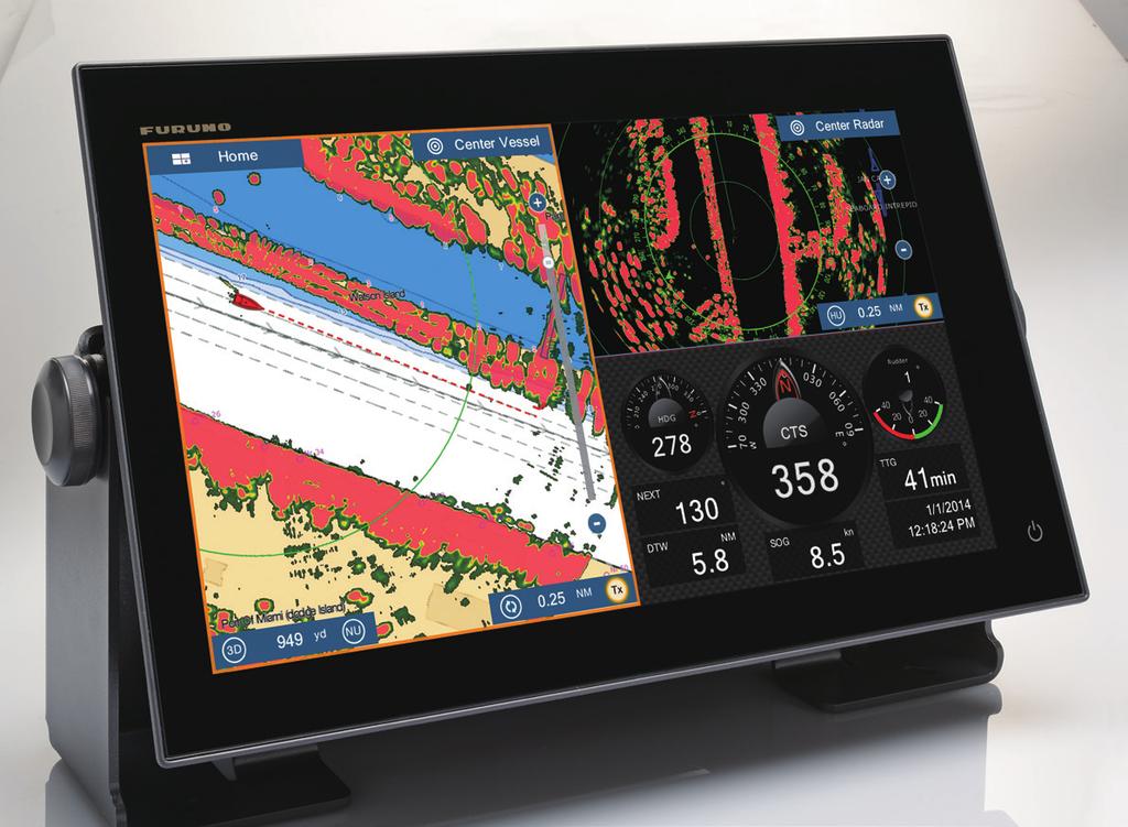
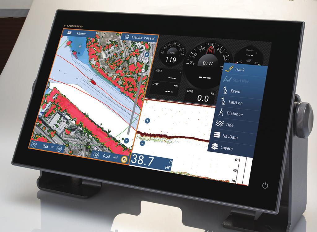
Adding a New Dimension to 3D
 POWERED BY Adding a New Dimension to 3D Onboard vessel navigation has undergone something of a revolution in recent years. Never before has so much information been available to you to improve and enhance
In-Band OAM Gigabit Ethernet to MM LC Fiber Media Converter - 550m, Metal Housing
 In-Band OAM Gigabit Ethernet to MM LC Fiber Media Converter - 550m, Metal Housing ET91000LCOAM *actual product may vary from photos DE: Bedienungsanleitung - de.startech.com FR: Guide de l'utilisateur
SAT IF distribution system
 7. Technical specifications Type cs43 RF input frequency range pr. 50-350 MHz inputs number 4 level pr. 55...88 dbµv 60...93 dbµv symbol rate 3 45 Ms/s return loss/impedance > 0 db/75 Ω LNB powering/control
Video Extender DS128 DSRXL. Instruction Manual. 8-Port Cat5 VGA Digital Signage Broadcaster with RS232 and Audio
 DS128 DSRXL Instruction Manual Video Extender 8-Port Cat5 VGA Digital Signage Broadcaster with RS232 and Audio Cat5 VGA Digital Signage Receiver with RS232 and Audio FCC Compliance Statement This equipment
GV-3D People Counter 3DPCV10-A
 GV-3D People Counter User's Manual Before attempting to connect or operate this product, please read these instructions carefully and save this manual for future use. 3DPCV10-A 2013 GeoVision, Inc. All
DT1-PCM21. for Porsche PCM2.1 navigation systems
 Product features dvblogic DVB-T Tuner for Porsche PCM2.1 navigation systems Full plug and play vehicle-specific dual DVB-T Tuner + USB-AV-Player DVB-T-Tuner MPEG4 compatible (HD) USB-AV-Player for USB-media
COPYRIGHT NOVEMBER-1998
 Application Notes: Interfacing AG-132 GPS with G-858 Magnetometer 25430-AM Rev.A Operation Manual COPYRIGHT NOVEMBER-1998 GEOMETRICS, INC. 2190 Fortune Drive, San Jose, Ca 95131 USA Phone: (408) 954-0522
Installation instructions for Brookhouse NMEA multiplexer model AISC
 Installation instructions for Brookhouse NMEA multiplexer model AISC General This addendum describes connections and features of multiplexer model AISC where they are different from the standard Brookhouse
Gazer VI700A-SYNC/IN and VI700W- SYNC/IN INSTALLATION MANUAL
 Gazer VI700A-SYNC/IN and VI700W- SYNC/IN INSTALLATION MANUAL Contents List of compatible cars... 3 Package contents... 4 Special information... 6 Car interior disassembly and connection guide for Ford
E-MANUAL. Thank you for purchasing this Samsung product. To receive more complete service, please register your product at.
 E-MANUAL Thank you for purchasing this Samsung product. To receive more complete service, please register your product at www.samsung.com/register Model Serial No. Contents Quick Guides Connecting the
DVB-LR10. Compatible with Land Rover touch-screen navigation systems version 2
 dvblogic DVB-T Tuner Compatible with Land Rover touch-screen navigation systems version 2 Product features full plug and play vehicle-specific dual DVB-T Tuner with two active DVB-T glass-mount antennas
SELENA GPS ATOMIC CLOCK ( Option # 725GPS )
") SELENA ATOMIC CLOCK ( Option # ) Rev. GS34 ATOMIC CLOCK WITH ( Optional Feature ) ( option # ) In all Atomic clock with receiver option configurations the functions Fn 70 must be enabled. The Daylight
SELENA ATOMIC CLOCK ( Option # ) Rev. GS34 ATOMIC CLOCK WITH ( Optional Feature ) ( option # ) In all Atomic clock with receiver option configurations the functions Fn 70 must be enabled. The Daylight
2x50 ETHERNET MODULE
 Kokkedal Industripark 4 DK-2980 Kokkedal Denmark info@eilersen.com Tel +45 49 180 100 Fax +45 49 180 200 2x50 ETHERNET MODULE Status and weight transfer using EtherNetIP Applies for: Program no.: ETHERNETIP.121113.1v0
Configuration Vestas VMP3500
 Configuration Vestas VMP3500 1. Table of contents 1. Table of contents... 2 2. Introduction... 3 3. Vestas turbines (RCS)... 4 3.1. VMP 3500 controller... 4 3.2. Communication with the CT3230 current loop
PQ-Box 100 Quick Start Instructions
 PQ-Box 100 Quick Start Instructions These instructions are provided for the purpose on providing a quick start to PQ-Box 100 installation and operation. Please refer to the user handbook for full details.
FS-HDR Quick Start Guide
 FS-HDR Quick Start Guide Overview FS-HDR, a 1RU, rack-mount, universal converter/frame synchronizer, is designed specifically to meet the HDR (High Dynamic Range) and WCG (Wide Color Gamut) needs of broadcast,
C Module Description
 ASI Distribution Amplifier with Signal Inversion C Module Description The is an ASI distribution amplifier with up to 8 outputs in double width or 4 outputs in single width. The input is transformer coupled
Video Server SED-2100R/S. Quick Installation Guide
 Video Server SED-2100R/S Quick Installation Guide Feb.10,2006 1 1 Getting Started 1.1 PACKAGE CONTENTS SED-2100 Warranty Card Software CD Hook up & Screws Terminal Blocks for Power & DI/O Power Adaptor
Manual. Simrad IS80 Heading Repeater HR80. English
 Manual Simrad IS80 Heading Repeater HR80 English www.simrad-yachting.com A brand by Navico - Leader in Marine Electronics Manual Simrad IS80 Heading Repeater HR80 English Document no: 20223194 Revision:
FS-HDR Quick Start Guide
 FS-HDR Quick Start Guide Overview FS-HDR, a 1RU, rack-mount, universal converter/frame synchronizer, is designed specifically to meet the HDR (High Dynamic Range) and WCG (Wide Color Gamut) needs of broadcast,
DVB-C25. Compatible with navigation systems Mercedes Benz Comand 2.5
 dvblogic DVB-T Tuner Compatible with navigation systems Mercedes Benz Comand 2.5 Product features full plug and play vehicle-specific dual DVB-T Tuner with two active DVB-T glass-mount antennas integrated
LWX-1. Satellite Weather Radio Module Installation Instructions A
 LWX-1 Satellite Weather Radio Module Installation Instructions 988-0158-13A Copyright 2009 Navico All rights reserved. No part of this manual may be copied, reproduced, republished, transmitted or distributed
RDS: The RDS, or Radio Data System, is supported in the g! interface where available.
 Manufacturer: Integra Integration Note Model Number(s): Integra 20.3/30.3/40.3/50.3/70.3/80.3 Core Module Version: 5.4 Comments: FW 1.09 (1091-0999-0210-9105) Document Revision Date: 1/15/2013 OVERVIEW
Intellian MIM Serial Number
 Intellian MIM Serial Number This serial number will be required for all troubleshooting or service calls made regarding this product. Notice All Right Reserved Intellian MIM and Intellian are the registered
Digital Video Recorder
 Digital Video Recorder Quick Operation Guide UD.6L0202B0067A02 Thank you for purchasing our product. If there is any question or request, please do not hesitate to contact dealer. This manual is applicable
Design and Use of a DTV Monitoring System consisting of DVQ(M), DVMD/DVRM and DVRG
, DVMD/DVRM and DVRG") Design and Use of a DTV Monitoring System consisting of DVQ(M), DVMD/DVRM and DVRG When monitoring transmission systems it is often necessary to control the monitoring equipment and to check the measurement
Design and Use of a DTV Monitoring System consisting of DVQ(M), DVMD/DVRM and DVRG When monitoring transmission systems it is often necessary to control the monitoring equipment and to check the measurement
PLASMA MONITOR (PT20 UVVis) USER GUIDE
 USER GUIDE") Thin Film Measurement solution Software, sensors, custom development and integration PLASMA MONITOR (PT20 UVVis) USER GUIDE August 2012 Plasma monitor with VFT probe. INTRODUCTION Plasma Monitor includes
Thin Film Measurement solution Software, sensors, custom development and integration PLASMA MONITOR (PT20 UVVis) USER GUIDE August 2012 Plasma monitor with VFT probe. INTRODUCTION Plasma Monitor includes
HDMI Over IP Extender Kit - 4K
 HDMI Over IP Extender Kit - 4K Product ID: ST12MHDLAN4K This HDMI over IP extender gives you the flexibility to locate digital signage displays where you need them. Using your local network to extend a
DS-7200HVI/HFI-SH Series DVR Quick Operation Guide
 DS-7200HVI/HFI-SH Series DVR Quick Operation Guide UD.6L0202B0019A01 Thank you for purchasing our product. If there is any question or request, please do not hesitate to contact dealer. This manual is
C Module Description
 IQMMX -Input Router & ASI Distribution Amplifier C Module Description The IQMMX is an ASI to 1 switch, distribution amplifier and transport stream switcher with up to 8 outputs in double width form or
Mini Micro Pulse Lidar System
 Mini Micro Pulse Lidar System MiniMPL-532-C Sensor Suite Operations Manual Version: June 2016 THIS PAGE INTENTIONALLY LEFT BLANK 2 Table of Contents MINIMPL SENSOR SUITE SYSTEM: RECORD OF PURCHASE... 4
First Time Setup Guide
 First Time Setup Guide www.exhibio.com 1.877.EXHIBIO (394.4246) Exhibio ST-200 Components & Accessories Standing Mount TV Tuner with Input Cable (USB 2.0 only) VESA Mount Over-the-Air Antenna Power Adapter
Technical Notification
 Technical Notification Document number: 95-137279-A Date: November 2012 SAILOR 900 VSAT SkyEdge II Access Modem setup. Subject: This technical note describes the installation and configuration of the SkyEdge
YAMAHA 03D SERIAL AUDIO MIXER
 TECH NOTE Fastrack VS Verion 1.0 and later YAMAHA 03D SERIAL AUDIO MIXER The Fastrack VS hybrid editing system interfaces to the 03D Serial Audio Mixer with a 6-pin DIN to 9-pin RS-422 serial control cable
DT1-NTG2. Compatible with Mercedes Benz Comand APS NTG2 navigation systems
 dvblogic DVB-T Tuner Compatible with Mercedes Benz Comand APS NTG2 navigation systems Product features Full plug and play vehicle-specific dual DVB-T Tuner + USB-AV-Player DVB-T-Tuner MPEG4 compatible
E-MANUAL. Thank you for purchasing this Samsung product. To receive more complete service, please register your product at.
 E-MANUAL Thank you for purchasing this Samsung product. To receive more complete service, please register your product at www.samsung.com/register Model Serial No. Contents Connecting Antenna and External
JAMAR TRAX RD Detector Package Power Requirements Installation Setting Up The Unit
 JAMAR TRAX RD The TRAX RD is an automatic traffic recorder designed and built by JAMAR Technologies, Inc. Since the unit is a Raw Data unit, it records a time stamp of every sensor hit that occurs during
NETWORK COMPASS USER MANUAL CONTENTS
 CONTENTS NETWORK COMPASS USER MANUAL GENERAL INTRODUCTION TO B&G NETWORK...2 INTRODUCTION TO NETWORK COMPASS...3 COMPASS DISPLAY UNIT...4 EXAMPLE SYSTEMS USING NETWORK COMPASS...4 INITIAL POWER-UP...5
CHAPTER 3 EXPERIMENTAL SETUP
 CHAPTER 3 EXPERIMENTAL SETUP In this project, the experimental setup comprised of both hardware and software. Hardware components comprised of Altera Education Kit, capacitor and speaker. While software
MyFlyDream TeleFlyPro V1.04
 MyFlyDream TeleFlyPro V1.04 www.myflydream.com Notes Thank you for purchasing the MyFlyDream TeleFlyPro (hereinafter referred to as TFPro). Please follow this manual to get familiar with the TFPro and
1 Unpack. Taking the TV Out of the Box. Included in this Box. Remote Control. Stand Parts and Cables. Also included
 1 Unpack Taking the TV Out of the Box Warning: Do not touch the TV s screen when you take it out of the box. Hold it by its edges only. If you touch the screen, you can cause the TV panel to crack. Included