LMH0340/LMH0341 SerDes EVK User Guide
|
|
|
- Marylou Walton
- 5 years ago
- Views:
Transcription


1 LMH0340/LMH0341 SerDes EVK User Guide July 1, 2008 Version
2 1... Overview Evaluation Kit (SD3GXLEVK) Contents Hardware Setup ALP100 BOARD (MAIN BOARD) DESCRIPTION SD340EVK BOARD DESCRIPTION SD341EVK BOARD DESCRIPTION LMH0340/LMH0341 SERDES EVK DEFAULT CONNECTIONS (LOOP-BACK) Software Setup SYSTEM REQUIREMENTS INSTALLATION STARTUP Evaluating Hardware TEST SETUPS Loop-back Tests External Tests Pass-through Tests EVALUATING SD/HD/3G SDI Video Pattern Generation: Transmit Data Path Embeded Audio Generation: Transmit Data Path Video Format Detect, Audio Detect, CRC and EDH Check: Receive Data Path Deserializer Re-clocked Loop-through: Receive Data Path Pass-through: Receive, Transmit Data Path EVALUATING USING BIT ERROR RATE TESTER ENGINE Data Pattern Generation: Transmit Data Path Error Injection: Transmit Data Path Data Pattern Verification: Receive Data Path Deserializer Re-clocked Loop-through: Receive Data Path External Clock I/O Documentation SCHEMATICS, BOMS, AND DATA SHEETS REFERENCE FPGA IP Part Numbers Trouble Shooting 19 2
3 1 Overview The LMH0340/LMH0341 SerDes Evaluation Kit (EVK) enables rapid evaluation of the LMH0340/0341 serializer and deserializer in Serial Digital Interface (SDI) applications. All parts in this family can be supported by this EVK. Tables 1 and 2 list the parts in the family and their features. Table 1) Serializers Device SMPTE 424M Support SMPTE 292M Support SMPTE 259M Support DVB-ASI Support SMPTE Compliant Cable Driver LMH0340 LMH0040 LMH0070 LMH0050 Table 2) Deserializers Device SMPTE 424M Support SMPTE 292M Support SMPTE 259M Support DVB-ASI Support Active Loopthrough LMH0341 LMH0041 LMH0071 LMH0051 Examples of firmware are provided for the Standard Definition SMPTE 259M (SD-SDI) interface, the High Definition SMPTE 292M (HD-SDI) interface, the 3G SMPTE 424M (3G-SDI) interface, and general purpose data generator with Bit Error Rate Tester (BERT). A graphical user interface allows managing the FPGA firmware functions and the LMH0340/0341 devices. 2 Evaluation Kit (SD3GXLEVK) Contents The EVK contains the following parts: 5 V 2.5 A AC/DC power supply USB cable LMH0340/LMH0341 SerDes EVK User Guide (See Documentation section for more detail) LMH0340/LMH0341 SerDes EVK board assembly consisting of: o ALP100 Analog LaunchPAD board with a Xilinx Spartan-3E FPGA o SD340EVK serializer board with the LMH0340 serializer IC* o SD341EVK deserializer board with the LMH0344 equalizer IC and LMH0341 deserializer IC* o Mounting plate, spacers, and screws *Note: These boards may be populated with lower speed grade products for HD and SD date rates when specifically requested by a customer. The documentation for operation is the same regardless of the maximum data rate. 3
 to allow daughter boards to be attached.")


4 3 Hardware Setup The LMH0340/LMH0341 SerDes EVK includes 3 printed circuit boards. The main board has 4 multi-pin connectors (J1 J4) to allow daughter boards to be attached. Power, control bus, and LVDS bus signals are supplied to the daughter boards through these connectors. A Xilinx Spartan-3E FPGA is the heart of the main board. It provides the SD/HD/3G SDI and general purpose stacks as well as the control interface to a PC through a USB cable. There are 2 daughter boards that connect to the main board. These are evaluation boards for the LMH0340 serializer and LMH0341 deserializer. They allow inexpensive FPGAs to deliver SD/HD/3G SDI data rates on SDI coax cable. Figure 1) EVK Block Diagram Figure 2) EVK Signal Flow 4


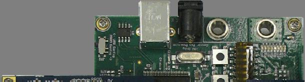
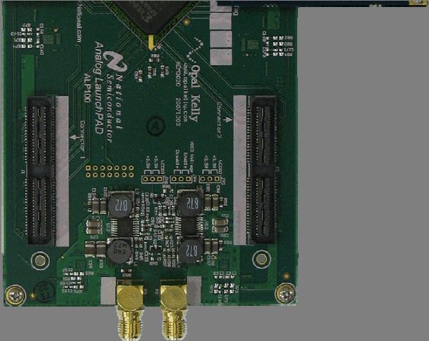
5 3.1 ALP100 Board (Main Board) Description The main board has a Xilinx Spartan-3E FPGA. The FPGA provides the SD/HD/3G SDI and general purpose stacks as well as the control interfaces through the supplied bit image files. Two daughter boards are connected to the main board through 2 of the 4 high speed connectors (J2 and J4). The connectors provide power, control bus, and data bus. In some FPGA configurations the SMA connectors P2 and P3 can be used as the FPGA clock source or output the FPGA clocks used for the serializer and deserializer. The main board communicates to a PC through a USB cable. P2 J4 J2 P3 Figure 3) ALP100 Board 3.2 SD340EVK Board Description The serializer board features the 5:1 LMH0340 serializer IC with integrated cable driver. This device supports SD, HD, or 3G SDI interfaces on a single 75 ohm BNC connector (J1). Board ID: Connector J1 Output Impedance: LMH0340 Serializer Board 75 ohm LMH0340 SDI Out J1 Figure 4) SD340EVK with LMH0340 Serializer 5
. The input signal on J1 is equalized, reclocked, and output on the 75 ohm BNC connector (J2).")
6 3.3 SD341EVK Board Description The deserializer board features the 1:5 LMH0341 deserializer IC and LMH0344 cable equalizer IC. It is capable of receiving SD, HD, or 3G SDI on a single 75 ohm BNC connector (J1). The input signal on J1 is equalized, reclocked, and output on the 75 ohm BNC connector (J2). J2 can be connected to an external analyzer for system evaluation. Board ID: LMH0341 Deserializer Board Connector J1/J2 Input/Output Impedance: 75 ohm LMH0344 SDI In J1 LMH0341 Re-clocked Loop-through Out Figure 5) SD341EVK with LMH0341 Deserializer 3.4 LMH0340/LMH0341 SerDes EVK Default Connections (Loop-back) This connection setup is for the loop-back tests shown in Figure 7, Section The LMH0340/LMH0341 EVK comes assembled with the deserializer board connected to J2 of the main board and the serializer board connected to J4 of the main board. This can be seen in Figure 1 and 2, Section Connect a 75 ohm SDI coax cable from J1 of the serializer board to J1 of the deserializer board. 3. Connect the USB cable between the PC and main board. 4. Set the power supply voltage to 5V. 5. Connect the power supply to the main board. 6. Connect the power supply to a 120 V 60 Hz AC outlet. For additional connections see Section 5 Evaluating Hardware. 6
7 4 Software Setup 4.1 System Requirements Operating System: Windows XP or Vista USB: Installation Download the latest software from Extract the ALPUSBDrive.exe and ALPF_monthdayyear_major version_minor version.exe (ex. ALPF_ _124_0046.exe) files to a temporary location that can be deleted later. Make sure the ALP hardware is not connected to the PC. The following installation instructions are for the Windows XP Operating System. Install the USB driver Execute the USB driver installation program called ALPUSBDrive.exe that was extracted to a temporary location. This will load the driver files onto the PC in the temporary location. There are 3 steps to this: 1. Select the Next button. 2. Select the I agree button. 3. Select the Finish button. Power on the ALP hardware. There should be numerous LEDs turned on. Connect the PC and the ALP hardware together with the USB cable. The Found New Hardware Wizard will open. There are 4 steps to install the USB driver: 1. Select No, not this time then select the Next button. 2. Select Install the software automatically then select the Next button. Windows should find the driver. 3. Select Continue Anyway. 4. Select the Finish button. Install the ALP software Execute the ALP Setup Wizard program called ALPF_monthdayyear_major version_minor version.exe (ex. ALPF_ _124_0046.exe) that was extracted to a temporary location. There are 7 steps to the installation once the setup wizard is started: 1. Select the Next button. 2. Select I accept the agreement and then select the Next button. 3. Select the location to install the ALP software and then select the Next button. 4. Select the location for the start menu shortcut and then select the Next button. 5. There will then be a screen that allows the creation of a desktop and Quick Launch icon. After selecting the desired choices select the Next button. 6. The software will then be installed to the selected location. 7. Select the Finish button. The ALP software will start if Launch Analog LaunchPAD is checked. The software installation is complete. 7
8 4.3 Startup Make sure all the software has been installed and the hardware is powered on and connected to the PC. Execute Analog LaunchPAD from the start menu. The default start menu location is Programs\National Semiconductor Corp\Analog LaunchPAD vx.x.x\analog LaunchPAD. The application should come up in the state shown below. If it does not, see Section 8 Trouble Shooting ; otherwise, proceed to Section 5 Evaluating Hardware. Figure 6) Analog LaunchPAD Opening Screen 8
9 5 Evaluating Hardware The EVK is designed for flexible and accurate evaluation of LMH0340 and LMH0341. Evaluation can be performed using internal or external stimuli and monitoring devices. There is an internal pattern generator implemented in the FPGA that will generate test patterns to verify signal transmission and signal integrity. The pattern generator can generate various types of patterns including standard PRBS patterns, SD/HD/3G SDI static video patterns, and user defined statically repeating patterns. The internal BERT or external test equipment can be used to do a thorough evaluation of the EVK. 5.1 Test Setups Loop-back Tests In loop-back only mode the system performance can be determined by the internal pattern generator, internal BERT and internal wave form monitor. This is done by connecting the serializer board output to the deserializer board input on J1. SD341EVK Up to 3 Gbps Reception ALP100 Spartan 3E SD340EVK Up to 3 Gbps Transmission Figure 7) Loop-back Test Setup 9
10 5.1.2 External Tests The serializer and deserializer can be evaluated in more detail by connecting an external oscilloscope, a waveform monitor such as the Tektronix WFM700M or Omnitek LAB, or a general purpose serial bit error rate test set such as the Agilent N4903A J-BERT or the SyntheSys Research BERTScope. To evaluate the performance of the LMH0340 serializer, connect the output of the serializer board in parallel using an appropriate buffer/splitter. To evaluate the transmission signal integrity and the performance of the LMH0341 deserializer, connect to the deserializer re-clocked loop-through output on J2 of the deserializer board. The loop-back tests can be performed at the same time. SD341EVK Up to 3 Gbps Reception ALP100 Spartan 3E SD340EVK Up to 3 Gbps Transmission Figure 8) External Test Setup Pass-through Tests There are also two pass-through modes. Mode one takes the output of the receiver descrambler and sends the data to the transmitter scrambler. Mode two de-embeds the audio, re-inserts crc and trs values, and embeds up to four audio channels. Mode two will be made available in a future release. Connect the source generator to J1 of the deserializer board and connect the terminating device to J1 of the serializer board. Figure 9) Pass-through Test Setup 10

11 5.2 Evaluating SD/HD/3G SDI The EVK can be evaluated using the internal ALP software only or in conjunction with external test equipment. Section 5 Test Setups has further examples. Select ALP Board 1 in the Devices pull-down menu on the left. This will expose the ALP Board 1 window in the main area. Select the SDI tab in the ALP Board 1 window. Figure 10) Analog LaunchPAD Initial SDI Tab 11

12 ALP Board 1 window can be detached and resized by dragging the ALP Board 1 title bar. Figure 11 below shows the SDI results running. Figure 11) Analog LaunchPAD SDI Tab Running The text in Sections 5.2.1, 5.2.2, 5.2.3, 5.2.4, 5.2.5, and refers to Figure Video Pattern Generation: Transmit Data Path Static video frames can be sent from the serializer at either Standard Definition SMPTE 259M (SD-SDI), High Definition SMPTE 292M (HD-SDI), or 3G SMPTE 424M (3G-SDI) data rates. Dual link 3G is supported when two serializer boards and two deserializer boards are connected to the main board. The video pattern and format is selected in the SMPTE Data Stream Configuration group. Select the desired frame size and frame rate in the Video Standard drop down list. A video standard with a /M at the end means the data rate is divided by of the non- /M standards. Select the desired video pattern in the Video Pattern drop down list. The selected video pattern is shown in the Video Test Pattern group. Video frames are continuously sent to the serializer and all parameter changes will automatically occur. The waveform is output on the serializer board BNC connector J1. 12
13 Clicking the Start button in the SDI Start/Stop Control group will start updates of the status information in the Status group. This button label will change to Initializing and then Running. Click Stop to stop the updates of the status information. Status group shows the following transmit information: Tx Lock Status: green if signal present at input to serializer and serializer is locked to signal Tx Reset Status: green if serializer is not in reset All other information in the Status group is receiver information and is covered in Section Embeded Audio Generation: Transmit Data Path Audio can be embedded in the SMPTE 291M ancillary data. One of four SMPTE 299M audio groups can be embedded at a time. Each group contains four audio tones. 3G audio will be supported when the relevant SMPTE standard is finalized. All audio controls are located in the control labeled Audio Control group. If the Audio Embedding Enabled check box is selected, four tones will be embedded in the group selected in the Audio Group Select drop down list. The frequency of the tones can be changed by clicking the Audio Freq Change button. If a LM49350 board and break out board is connected to J1 of the ALP100, audio can be externally embedded/deembedded by checking the Source:Internal check box. This check box label shows the source of the embedded audio Video Format Detect, Audio Detect, CRC and EDH Check: Receive Data Path The LMH0341 on the deserializer board can receive and deserialize data at SD/HD/3G SDI data rates. The FPGA firmware can detect SMPTE 259M (SD-SDI), SMPTE 292M (HD-SDI), or SMPTE 424M (3G-SDI) video frames as well as SMPTE 299M embedded audio. Connect a standard SD, HD, or 3G SDI video source to the deserializer board BNC connector J1. The Status group contains all the received video and audio information. As mentioned in Section 5.2.1, the Start button in the SDI Start/Stop Control group must show Running or the status information is not updating. Status group shows the receiver information: Rx Lock Status: green if signal present at input to deserializer and deserializer is locked to signal Rx Reset Status: green if deserializer is not in reset Serial Bit Rate: serial bit rate of recovered serial data Lines Per Frame: total number of lines per frame Words Per Active Line: number of video samples per active line Total Active Lines: number of active lines per frame Words Per Total Line: number of samples per line including header, video, and ancillary data Frame Rate: number of frames per second Fields Per Frame: 1 for progressive scanning or 2 for interlaced scanning Frequency Label: SD, HD, HD/M, 3G, or 3G/M (/M indicates divide by 1.001) Format Name: short name for video format (lines per active frame, scanning format, fame rate) CRC Errors: accumulated luma (Y) and chroma (C B and C R ) CRC errors (HD and 3G) EDH Active Picture Errors: accumulated active picture errors (SD) EDH Full Field Errors: accumulated full field errors, includes active picture errors (SD) Audio Group 1 Present: embedded audio group 1 present if value is 1 Audio Group 2 Present: embedded audio group 2 present if value is 1 13
14 Audio Group 3 Present: embedded audio group 3 present if value is 1 Audio Group 4 Present: embedded audio group 4 present if value is Deserializer Re-clocked Loop-through: Receive Data Path The deserializer has a re-clocked loop-through output with cable driver. This is the clock recovered version of the signal present at the input to the deserializer. This feature is useful for sending a clean SDI signal to additional equipment. Enable the deserializer re-clocked loop-through mode by checking the Enable check box in the Loop Through group Pass-through: Receive, Transmit Data Path There is a pass-through mode on the SDI tab. In pass-through mode the signal at the output of the receiver descrambler is sent to the input transmitter scrambler. As long as the deserializer can recover the clock, the signal will be passed through to the output of the serializer even if the signal is not recognized as a standard video format. Enable pass-through mode by checking the Enable check box in the Pass Through group. The FPGA firmware and ALP software still has the capability to analyze the video frames and embedded audio coming from the deserializer. 14
 engine.")
15 5.3 Evaluating Using Bit Error Rate Tester Engine The EVK can be evaluated using the internal ALP software only or in conjunction with external test equipment. Section 5 Test Setups contains further examples. This section describes the usage of the ALP software with the internal Bit Error Rate Tester (BERT) engine. Select ALP Board 1 in the Devices pull-down menu on the left. This will expose the ALP Board 1 window in the main area. Select the BERT tab in the ALP Board 1 window. Figure 12) Analog LaunchPAD Initial BERT Tab 15

16 ALP Board 1 window can be detached and resized by dragging the ALP Board 1 title bar. Figure 13 below shows the BERT running. Figure 13) Analog LaunchPAD BERT Tab Running The text in Sections 5.3.1, 5.3.2, 5.3.3, 5.3.4, and refers to Figure Data Pattern Generation: Transmit Data Path The BERT tab can be used to send test patterns to the serializer at 270 Mbps, 1.5 Gbps or 3 Gbps. Select the desired pattern and whether SMPTE scrambling and NRZI is on in the BERT Pattern Select group. Select the desired data rate in the Serial Bit Rate Configuration group. When using a fixed pattern, the Scramble/NRZI check box may need to be checked in order for the deserializer to recover the clock. Scramble/NRZI should normally be checked. Click the Start button in the BERT Control group to send the selected pattern to the serializer. This button also shows the current status. After clicking the button it will read Init and then Running. The waveform is output on the serializer board BNC connector J1. If any of the settings in the BERT Pattern Select group are changed, click the Stop button and then the Start button for the change to take effect. Device Status group shows the following transmit information: Tx Lock: green if signal present at input to serializer and serializer is locked to signal 16
17 5.3.2 Error Injection: Transmit Data Path Errors can be injected into the transmit data to demonstrate how the link behaves under various conditions. The BERT Control group has three buttons that allow error injection. Clicking the Error button will inject an error once. Clicking the Burst Errors button will inject a burst of errors once. Clicking the Inject Errors will continuously inject bursts of errors. It will make the BERT look as though it is unlocked due to the high number of errors. The Inject Errors button must be clicked again to stop the errors Data Pattern Verification: Receive Data Path There is a BERT implemented in the FPGA on the ALP board. The BERT will try to lock to the pattern matching the settings in the BERT tab. Start the BERT by clicking the Start button in the BERT Control group. If the input signal on J1 of the deserializer board matches the settings in the BERT tab, the counters in the BERT Status group will accumulate. The counters can be cleared by clicking the Clear Counters button in the BERT Control group. There is also a graph that shows the bit errors vs. time in seconds. The plot can be shown by clicking the Plot Errors button. Device Status group and BERT Status group shows the following receiver information: Rx Lock: green if signal present at input to deserializer and deserializer is locked to signal Running: green if BERT is running Locked: green if BERT can lock to input data pattern No Errors: green if no bit errors have accumulated Bit Count: total bits accumulated x 106 (un-errored + errored bits) Errors: errored bits accumulated Ratio: ratio of Errors over Bit Count (bit error rate) Deserializer Re-clocked Loop-through: Receive Data Path The deserializer has a re-clocked loop-through output with cable driver. This is the clock recovered version of the signal present at the input to the deserializer. This feature is useful for sending a clean SDI signal to additional equipment. Enable the deserializer re-clocked loop-through mode by checking the Loop Through check box in the BERT Pattern Select group External Clock I/O The SMA connectors P2 and P3 can be used to drive or monitor the 1x clock of the FPGA serializer data path or monitor the 1x clock of the FPGA deserializer data path. The 1x clock is 1/20 of the serial clock rate. P2 is the clock input connector and P3 is the clock output connector. The function of P2 and P3 is selected by the radio buttons in the External Clock Control group. When switching between the LMK3000C and SMA Conn P2 radio buttons the BERT must be stopped and restarted. 17
18 6 Documentation Additional LMH0340/LMH0341 EVK documentation can be found at Schematics, BOMs, and Data Sheets All of the schematics and BOMs for the LMH0340/LMH0341 EVK can be found at the above URL. The datasheets can be found at There is also information for other SDI parts at this URL. Note: The BOM for the ALP100 board is not available. 6.2 Reference FPGA IP The reference FPGA IP source code and documentation will be made available after signing a Software License Agreement. Please speak to a National Semiconductor representative for more details. 7 Part Numbers Serializer Board: Deserializer Board: Analog LaunchPAD Board: LMH0340/LMH0341 Evaluation Kit: SD340EVK SD341EVK ALP100 SD3GXLEVK 18


19 8 Trouble Shooting If the following window opens after starting the ALP software double check the hardware setup. Figure 14) Analog LaunchPAD No Devices Error It may also be that the USB driver is not installed. Check the device manager. There should be an Opal Kelly XEM3020 device under the Universal Serial Bus Controllers as shown below in Figure 15. Figure 15) Windows XP, Analog LauchPAD USB Driver 19


20 The software should start with only the LMH0340 and LMH0340 in the Devices pull down menu. If there are more devices then the software is most likely in demo mode. When the ALP is operating in demo mode there is a (Demo Mode) indication in the lower left of the application status bar as shown in Figure 16. Figure 16) Analog LaunchPAD in Demo Mode Disable the demo mode by selecting the Preferences pull down menu and unchecking Enable Demo Mode. Figure 17) Analog LaunchPAD Preferences Menu 20
21 After demo mode is disabled, the ALP software will poll the ALP hardware. The ALP software will update and have only the LMH0340 and LMH0341 under the Devices pull down menu. Figure 18) Analog LaunchPAD Screen with Demo Mode Off 21
SDI Development Kit using National Semiconductor s LMH0340 serializer and LMH0341 deserializer
 User Guide: SDALTEVK HSMC SDI ADAPTER BOARD 9-Jul-09 Version 0.06 SDI Development Kit using National Semiconductor s LMH0340 serializer and LMH0341 deserializer Page 1 of 31 1...Overview 3 2...Evaluation
Implementing Audio IP in SDI II on Arria V Development Board
 Implementing Audio IP in SDI II on Arria V Development Board AN-697 Subscribe This document describes a reference design that uses the Audio Embed, Audio Extract, Clocked Audio Input and Clocked Audio
SDI Development Kit using National Semiconductor s LMH0340 serializer and LMH0341 deserializer
 User Guide: SDALTEVK HSMC SDI ADAPTER BOARD 9-Jul-09 Version 0.06 SDI Development Kit using National Semiconductor s LMH0340 serializer and LMH0341 deserializer Page 1 of 31 1...Overview 3 2...Evaluation
APPLICATION NOTE 4254 PRBS Mode Setup for the MAX9257/MAX9258 Evaluation Kit
 Maxim > Design Support > Technical Documents > Application Notes > High-Speed Interconnect > APP 4254 Keywords: PRBS, pseudo-random bit sequence, serializer, deserializer, eye diagram, ECU, bit error rate
LogiCORE IP Spartan-6 FPGA Triple-Rate SDI v1.0
 LogiCORE IP Spartan-6 FPGA Triple-Rate SDI v1.0 DS849 June 22, 2011 Introduction The LogiCORE IP Spartan -6 FPGA Triple-Rate SDI interface solution provides receiver and transmitter interfaces for the
AN 848: Implementing Intel Cyclone 10 GX Triple-Rate SDI II with Nextera FMC Daughter Card Reference Design
 AN 848: Implementing Intel Cyclone 10 GX Triple-Rate SDI II with Nextera FMC Daughter Card Reference Design Updated for Intel Quartus Prime Design Suite: 18.0 Subscribe Send Feedback Latest document on
SERDES Eye/Backplane Demo for the LatticeECP3 Serial Protocol Board User s Guide
 for the LatticeECP3 Serial Protocol Board User s Guide March 2011 UG24_01.4 Introduction This document provides technical information and instructions on using the LatticeECP3 SERDES Eye/Backplane Demo
IP LIVE PRODUCTION UNIT NXL-IP55
 IP LIVE PRODUCTION UNIT NXL-IP55 OPERATION MANUAL 1st Edition (Revised 2) [English] Table of Contents Overview...3 Features... 3 Transmittable Signals... 3 Supported Networks... 3 System Configuration
Model 5240 Digital to Analog Key Converter Data Pack
 Model 5240 Digital to Analog Key Converter Data Pack E NSEMBLE D E S I G N S Revision 2.1 SW v2.0 This data pack provides detailed installation, configuration and operation information for the 5240 Digital
SERDES Eye/Backplane Demo for the LatticeECP3 Versa Evaluation Board User s Guide
 SERDES Eye/Backplane Demo for the LatticeECP3 Versa Evaluation Board User s Guide May 2011 UG44_01.1 Introduction This document provides technical information and instructions on using the LatticeECP3
Rack-Mount Receiver Analyzer 101
 Rack-Mount Receiver Analyzer 101 A Decade s Worth of Innovation No part of this document may be circulated, quoted, or reproduced for distribution without prior written approval from Quasonix, Inc. Copyright
F M2SDI 2 Ch Tx & Rx. HD SDI Fiber Optic Link with RS 485 & Aux. User Manual
 User Manual F M2SDI 2 Ch Tx & Rx HD SDI Fiber Optic Link with RS 485 & Aux User Manual CHAPTER 1. SYSTEM INTRODUCTION 1.1 OVERVIEW 1.2 FEATURE 1.3 APPLICATION CHAPTER 2. F M2SDI ENCLOSURES 2.1 FRONT PANEL
MX/HD-SDI-3G. Transmit HD-SDI-3G signals over Fiber
 MX/HD-SDI-3G Transmit HD-SDI-3G signals over Fiber Key Features Transmit ASI or SDI signal over one single-mode Fiber Support data rate from 19.4Mb/s to 3Gb/s SMPTE 424M, SMPTE 292M, SMPTE 344M and SMPTE
EEG A1452 SCTE-104 Inserter Frame Card
 EEG A1452 SCTE-104 Inserter Frame Card Product Manual EEG Enterprises, Inc. 586 Main Street Farmingdale, New York 11735 TEL: (516) 293-7472 FAX: (516) 293-7417 Copyright EEG Enterprises, Inc. 2017 All
Transmission of High-Speed Serial Signals Over Common Cable Media
 July 008 Introduction Technical Note TN066 Designers are often faced with moving serial data from one location to another, over moderate distances, and in the most efficient manner. Transmitting large
Transmission of High-Speed Serial Signals Over Common Cable Media
 August 00 Introduction Technical Note TN066 Designers are often faced with moving serial data from one location to another, over moderate distances, and in the most efficient manner. Transmitting large
National Semiconductor s Serial Digital Interface (SDI) Smart SerDes
 Smart SerDes") SIGNAL PATH designer Tips, tricks, and techniques from the analog signal-path experts No. 113 Feature Article... 1-5 Sync Separator...4 Crosspoint Switch...7 A 3 Gbps SDI Connectivity Solution Supporting
SIGNAL PATH designer Tips, tricks, and techniques from the analog signal-path experts No. 113 Feature Article... 1-5 Sync Separator...4 Crosspoint Switch...7 A 3 Gbps SDI Connectivity Solution Supporting
C8000. sync interface. External sync auto format sensing : AES, Word Clock, Video Reference
 features Standard sync module for a frame Internal sync @ 44.1 / 48 / 88.2 / 96kHz External sync auto format sensing : AES, Word Clock, Video Reference Video Reference : Black Burst (NTSC or PAL) Composite
Hardware User s Manual
 Hardware User s Manual Megapixel Day & Night Economy Bullet Network Camera English 1 Table of Contents Before You Use This Product... 2 Regulatory Information... 3 Chapter 1 - Package Contents... 4 Chapter
INSTRUCTION MANUAL VF MultiDyne. Harnessing The Power of Light
 INSTRUCTION MANUAL VF-9000 SERIAL DIGITAL FIBER OPTIC TRANSPORT and DISTRIBUTION SYSTEM FOR SMPTE 259, 292, 424, DVB-ASI, with gigabit ethernet with SNMP & Web page monitoring and other protocols MultiDyne
IP LIVE PRODUCTION UNIT NXL-IP55 USO RESTRITO. OPERATION MANUAL 1st Edition (Revised 2) [English]
![IP LIVE PRODUCTION UNIT NXL-IP55 USO RESTRITO. OPERATION MANUAL 1st Edition (Revised 2) [English]](/thumbs/89/99059597.jpg "IP LIVE PRODUCTION UNIT NXL-IP55 USO RESTRITO. OPERATION MANUAL 1st Edition (Revised 2) [English]") IP LIVE PRODUCTIO UIT XL-IP55 USO RESTRITO OPERATIO MAUAL 1st Edition (Revised 2) [English] Table of Contents Overview... 3 Features... 3 Transmittable Signals... 3 Supported etworks... 3 System Configuration
IP LIVE PRODUCTIO UIT XL-IP55 USO RESTRITO OPERATIO MAUAL 1st Edition (Revised 2) [English] Table of Contents Overview... 3 Features... 3 Transmittable Signals... 3 Supported etworks... 3 System Configuration
SERIAL DIGITAL VIDEO FIBER OPTIC TRANSPORT & DISTRIBUTION MODULAR SYSTEM FOR HDTV & SDTV
 INSTRUCTION MANUAL HD-4000 Series OPENGEAR SERIAL DIGITAL VIDEO FIBER OPTIC TRANSPORT & DISTRIBUTION MODULAR SYSTEM FOR HDTV & SDTV MultiDyne Video at Light Speed 191 FOREST AVENUE LOCUST VALLEY, NY 11560-2132
Laboratory 4. Figure 1: Serdes Transceiver
 Laboratory 4 The purpose of this laboratory exercise is to design a digital Serdes In the first part of the lab, you will design all the required subblocks for the digital Serdes and simulate them In part
TECHNICAL MANUAL. Cheetah VIDEO MATRIX ROUTERS 3G VIDEO INPUT CARD WITH AUDIO DE-EMBEDDING AND 3G VIDEO OUTPUT CARD WITH AUDIO EMBEDDING
 TECHNICAL MANUAL Cheetah VIDEO MATRIX ROUTERS 3G VIDEO INPUT CARD WITH AUDIO DE-EMBEDDING AND 3G VIDEO OUTPUT CARD WITH AUDIO EMBEDDING Publication: 81-9059-0658-0, Rev. A August, 2009 Thank You!! for
CobraNet Bundle Assignment Procedure Using CobraNet Discovery
 Summary This procedure will allow Q-Sys to integrate with an existing CobraNet system by providing instructions on setting up CobraNet Assignments for the Q-Sys CCN32 CobraNet Card. NOTE: If the CCN32
SDI-MP1010-GM-60P-M-RA 3G/HD-SDI Output Video Transceiver. SDI-MP1010-GM-60P-M-RA Features. Block Diagram SDI-MP1010-GM-60P-M-RA.
 This is a family of small form factor modules for formatting and converting generic digital video streams to standard compliant formats. Different interface standards are supported from the transmitter
Product Catalog. Route - Transport - Extend - Convert - Scale. Multimedia Products for HDMI and DVI. 3G sdi OCT-2010-C
 Product Catalog Route - Transport - Extend - Convert - Scale Multimedia Products for HDMI and DVI 3G sdi OCT-2010-C Quick Reference Guide RS-232 INPUT 2 INPUT 4 OUTPUT 2 OUTPUT 4 OUTPUT 6 OUTPUT 8 INPUT
White Paper Lower Costs in Broadcasting Applications With Integration Using FPGAs
 Introduction White Paper Lower Costs in Broadcasting Applications With Integration Using FPGAs In broadcasting production and delivery systems, digital video data is transported using one of two serial
SingMai Electronics SM06. Advanced Composite Video Interface: HD-SDI to acvi converter module. User Manual. Revision 0.
 SM06 Advanced Composite Video Interface: HD-SDI to acvi converter module User Manual Revision 0.4 1 st May 2017 Page 1 of 26 Revision History Date Revisions Version 17-07-2016 First Draft. 0.1 28-08-2016
VIODC SDI Demonstration
 VIODC SDI Demonstration User Guide R R Xilinx is disclosing this Document and Intellectual Property (hereinafter the Design ) to you for use in the development of designs to operate on, or interface with
User Instruction Manual IQSDA30/IQSDA32. Intelligent Reclocking High Performance HD-SDI/SD-SDI Distribution Amplifiers. snellgroup.
 User Instruction Manual IQSDA30/IQSDA32 Intelligent Reclocking High Performance HD-SDI/SD-SDI Distribution Amplifiers snellgroup.com IQSDA30/IQSDA32 www.snellgroup.com Information and Notices Information
Intel FPGA SDI II IP Core User Guide
 Intel FPGA SDI II IP Core User Guide Updated for Intel Quartus Prime Design Suite: 17.1 Subscribe Send Feedback Latest document on the web: PDF HTML Contents Contents 1 Intel FPGA SDI II IP Core Quick
Acasual observer would note that there are many different broadcast. SIGNAL PATH designer
 SIGNAL PATH designer Tips, tricks, and techniques from the analog signal-path experts No. 106 Feature Article...1-7 High Performance Video Solutions...2 HD-SDI Signal Path Solutions...4-5 Design Tools...8
GALILEO Timing Receiver
 GALILEO Timing Receiver The Space Technology GALILEO Timing Receiver is a triple carrier single channel high tracking performances Navigation receiver, specialized for Time and Frequency transfer application.
AT780PCI. Digital Video Interfacing Products. Multi-standard DVB-T2/T/C Receiver & Recorder & TS Player DVB-ASI & DVB-SPI outputs
 Digital Video Interfacing Products AT780PCI Multi-standard DVB-T2/T/C Receiver & Recorder & TS Player DVB-ASI & DVB-SPI outputs Standard Features - PCI 2.2, 32 bit, 33/66MHz 3.3V. - Bus Master DMA, Scatter
Using SignalTap II in the Quartus II Software
 White Paper Using SignalTap II in the Quartus II Software Introduction The SignalTap II embedded logic analyzer, available exclusively in the Altera Quartus II software version 2.1, helps reduce verification
Serial Digital Interface II Reference Design for Stratix V Devices
 Serial Digital Interface II Reference Design for Stratix V Devices AN-673 Application Note This document describes the Altera Serial Digital Interface (SDI) II reference design that demonstrates how you
C8491 C8000 1/17. digital audio modular processing system. 3G/HD/SD-SDI DSP 4/8/16 audio channels. features. block diagram
 features 4 / 8 / 16 channel LevelMagic2 SDI-DSP with level or loudness (ITU-BS.1770-1/ ITU-BS.1770-2, EBU R128) control 16 channel 3G/HD/SD-SDI de-embedder 16 in 16 de-embedder matrix 16 channel 3G/HD/SD-SDI
AT720USB. Digital Video Interfacing Products. DVB-C (QAM-B, 8VSB) Input Receiver & Recorder & TS Player DVB-ASI & DVB-SPI outputs
 Input Receiver & Recorder & TS Player DVB-ASI & DVB-SPI outputs") Digital Video Interfacing Products AT720USB DVB-C (QAM-B, 8VSB) Input Receiver & Recorder & TS Player DVB-ASI & DVB-SPI outputs Standard Features - High Speed USB 2.0. - Windows XP, Vista, Win 7 ( 64bit
Digital Video Interfacing Products AT720USB DVB-C (QAM-B, 8VSB) Input Receiver & Recorder & TS Player DVB-ASI & DVB-SPI outputs Standard Features - High Speed USB 2.0. - Windows XP, Vista, Win 7 ( 64bit
Simple Media Platform Quick Installation Guide V1.0-N. Simple Media Platform. Quick Installation Guide
 Simple Media Platform Quick Installation Guide 1. Installation Instruction 1.1 Mounting unit to a 19 rack When selecting the installation site, try to comply with the following: Protective Ground - The
Model 7600 HD/SD Embedder/ Disembedder Data Pack
 Model 7600 HD/SD Embedder/ Disembedder Data Pack E NSEMBLE D E S I G N S Revision 2.1 SW v2.0.1 This data pack provides detailed installation, configuration and operation information for the 7600 HD/SD
CLC011 Serial Digital Video Decoder
 CLC011 Serial Digital Video Decoder General Description National s Comlinear CLC011, Serial Digital Video Decoder, decodes and descrambles SMPTE 259M standard Serial Digital Video datastreams with serial
Model 4455 ASI Serial Digital Protection Switch Data Pack
 Model 4455 ASI Serial Digital Protection Switch Data Pack Revision 1.5 SW v2.2.11 This data pack provides detailed installation, configuration and operation information for the 4455 ASI Serial Digital
Kramer Electronics, Ltd. USER MANUAL VM-20HD. Dual 1:10 HD/SD SDI Distribution Amplifier
 Kramer Electronics, Ltd. USER MANUAL VM-20HD Dual 1:10 HD/SD SDI Distribution Amplifier Contents Contents 1 Introduction 1 2 Getting Started 1 2.1 Quick Start 2 3 Overview 3 4 Your VM-20HD Dual 1:10 HD/SD
PCIe-FRM21. User s Manual
 PCIe-FRM21 User s Manual Windows, Windows2000, Windows NT and Windows XP are trademarks of Microsoft. We acknowledge that the trademarks or service names of all other organizations mentioned in this document
SMPTE 292M EG-1 Color Bar Generation, RP 198 Pathological Generation, Grey Pattern Generation IP Core - AN4088
 SMPTE 292M EG-1 Color Bar Generation, RP 198 Pathological Generation, Grey Pattern Generation IP Core - AN4088 January 18, 2005 Document No. 001-14938 Rev. ** - 1 - 1.0 Introduction...3 2.0 Functional
SingMai Electronics SM06. Advanced Composite Video Interface: DVI/HD-SDI to acvi converter module. User Manual. Revision th December 2016
 SM06 Advanced Composite Video Interface: DVI/HD-SDI to acvi converter module User Manual Revision 0.3 30 th December 2016 Page 1 of 23 Revision History Date Revisions Version 17-07-2016 First Draft. 0.1
C8188 C8000 1/10. digital audio modular processing system. 4 Channel AES/EBU I/O. features. block diagram. 4 balanced AES inputs
 features 4 balanced AES inputs Input Sample Rate Converters (SRC) 4 balanced AES outputs Relay bypass for pairs of I/Os Relay wait time after power up Master mode (clock master for the frame) 25pin Sub-D,
TL8651 3G/HD-SDI Output Video Transceiver. TL8651 Features. Block Diagram TL8651 3G/HD-SDI. 1080p p50
 Thunder Link is a family of small form factor modules for formatting and converting generic digital video streams to standard compliant formats. Different interface standards are supported from the transmitter
FiberLink 3355 Series
 MANUAL Link 3355 Series 3G/HD/SD-SDI to DVI Optical Receiver Installation and Operations Manual WWW.ARTEL.COM Contents Contents Welcome....3 Features....3 Package Contents....3 Technical Specifications
FS3. Quick Start Guide. Overview. FS3 Control
 FS3 Quick Start Guide Overview The new FS3 combines AJA's industry-proven frame synchronization with high-quality 4K up-conversion technology to seamlessly integrate SD and HD signals into 4K workflows.
Omega 4K/UHD Three-Input Switcher. Introduction. Applications. for HDMI and USB-C with HDBaseT and HDMI Outputs
 Introduction The Atlona AT-OME-ST31 is a 3 1 switcher and HDBaseT transmitter with HDMI and USB-C inputs. It features mirrored HDMI and HDBaseT outputs and is HDCP 2.2 compliant. The USB-C input is ideal
EXOSTIV TM. Frédéric Leens, CEO
 EXOSTIV TM Frédéric Leens, CEO A simple case: a video processing platform Headers & controls per frame : 1.024 bits 2.048 pixels 1.024 lines Pixels per frame: 2 21 Pixel encoding : 36 bit Frame rate: 24
Installation & Operational Manual
 Radiant Communications Corporation 5001 Hadley Road South Plainfield NJ 07080 Tel (908) 757-7444 Fax (908) 757-8666 WWW.RCCFIBER.COM QRF5000M MDU ENCODER Installation & Operational Manual Rev.A2 1. Introduction
CHAPTER 3 EXPERIMENTAL SETUP
 CHAPTER 3 EXPERIMENTAL SETUP In this project, the experimental setup comprised of both hardware and software. Hardware components comprised of Altera Education Kit, capacitor and speaker. While software
DIGILINK DLT710 FUNCTION MODULE
 MANUAL DIGILINK DLT710 FUNCTION MODULE Multi-Format Digital Video Generator and Tester Installation and Operations Manual WWW.ARTEL.COM DLT710 Generator/Test Module Multi-Format Digital Video Generator
Design and Implementation of SOC VGA Controller Using Spartan-3E FPGA
 Design and Implementation of SOC VGA Controller Using Spartan-3E FPGA 1 ARJUNA RAO UDATHA, 2 B.SUDHAKARA RAO, 3 SUDHAKAR.B. 1 Dept of ECE, PG Scholar, 2 Dept of ECE, Associate Professor, 3 Electronics,
Modular Matrix Solution. Complete A/V Signal Control in One Expandable System.
 Modular Matrix Solution Complete A/V Signal Control in One Expandable System www.aten.com Overview When video is displayed across multiple screens to maximize marketing, live broadcasting or real-time
F M1SDI 1 Ch Tx & Rx. HD SDI Fiber Optic Link with RS 485. User Manual
 User Manual F M1SDI 1 Ch Tx & Rx HD SDI Fiber Optic Link with RS 485 User Manual 1Introduction 1.1Overview 1.2Features 1.3Application 2 Panel 2.1 Front Panel 2.2 Rear Panel 3Technical Specification Contents
MSP 200PRO Quick Start
 MSP 200PRO Quick Start Touch Screen control Output a range of signal types Set and select from a range of common output formats Audio output test included Genlock Y&HS outputs Input live signals for preview
Quick Start for TrueRTA (v3.5) on Windows XP (and earlier)
 on Windows XP (and earlier)") Skip directly to the section that covers your version of Windows (XP and earlier, Vista or Windows 7) Quick Start for TrueRTA (v3.5) on Windows XP (and earlier) Here are step-by-step instructions to get
Skip directly to the section that covers your version of Windows (XP and earlier, Vista or Windows 7) Quick Start for TrueRTA (v3.5) on Windows XP (and earlier) Here are step-by-step instructions to get
SD/HD/3G-SDI Video + Power + Data RS-485 Transmission over Coax Kit
 User Manual SD/HD/3G-SDI Video + Power + Data RS-485 Transmission over Coax Kit HD-SDE-VDK Tx Camera Side Rx DVR Side HD-SDE-VDT SD-6b SD-6a The power are only for the devices, not for camera. Repeater
AT660PCI. Digital Video Interfacing Products. DVB-S2/S (QPSK) Satellite Receiver & Recorder & TS Player DVB-ASI & DVB-SPI outputs
 Satellite Receiver & Recorder & TS Player DVB-ASI & DVB-SPI outputs") Digital Video Interfacing Products AT660PCI DVB-S2/S (QPSK) Satellite Receiver & Recorder & TS Player DVB-ASI & DVB-SPI outputs Standard Features - PCI 2.2, 32 bit, 33/66MHz 3.3V. - Bus Master DMA, Scatter
Digital Video Interfacing Products AT660PCI DVB-S2/S (QPSK) Satellite Receiver & Recorder & TS Player DVB-ASI & DVB-SPI outputs Standard Features - PCI 2.2, 32 bit, 33/66MHz 3.3V. - Bus Master DMA, Scatter
Serial Digital Interface Reference Design for Stratix IV Devices
 Serial Digital Interface Reference Design for Stratix IV Devices AN-600-1.2 Application Note The Serial Digital Interface (SDI) reference design shows how you can transmit and receive video data using
Quick Reference Manual
 Quick Reference Manual V1.0 1 Contents 1.0 PRODUCT INTRODUCTION...3 2.0 SYSTEM REQUIREMENTS...5 3.0 INSTALLING PDF-D FLEXRAY PROTOCOL ANALYSIS SOFTWARE...5 4.0 CONNECTING TO AN OSCILLOSCOPE...6 5.0 CONFIGURE
QUICK START GUIDE QT ANALOG HD CAMERA & DVR BUNDLE ENGLISH
 QUICK START GUIDE QT ANALOG HD CAMERA & DVR BUNDLE ENGLISH Table of Contents Welcome What s Included...3 Understanding your DVR...4 Get Connected Registration...5 Connect Your Cameras...5 Connect DVR to
Copyright 2013 ACURA Global. UHF860 RFID READER. User s manual. English draft TM970180
 Copyright 03 ACURA Global. UHF860 RFID READER User s manual English draft TM97080 April 0, 03 Copyright 03: without a written approval from ACURA Global Inc, this document is not allowed to be duplicated
V pro8 QUICK START GUIDE
 QUICK START GUIDE Welcome to your V pro8 FIRST STEPS POWERING ON CONNECTING YOUR COMPUTER Thank you for buying the Lawo V pro8, a true high-quality product developed and manufactured in Rastatt, Germany.
3Gb/s, HD, SD quad split to WUXGA converter / multiview building block with timecode input COPYRIGHT 2011 AXON DIGITAL DESIGN BV ALL RIGHTS RESERVED
 GQW-HQW-SQW220 3Gb/s, HD, SD quad split to WUXGA converter / multiview building block with timecode input A Synapse product COPYRIGHT 2011 AXON DIGITAL DESIGN BV ALL RIGHTS RESERVED NO PART OF THIS DOCUMENT
Lab experience 1: Introduction to LabView
 Lab experience 1: Introduction to LabView LabView is software for the real-time acquisition, processing and visualization of measured data. A LabView program is called a Virtual Instrument (VI) because
Tech Data DE-EMBEDDER + AUDIO/VIDEO SPLITTER
 1 Description Audio Press Splitter Individual amplification, monitoring & isolation 3G / HD / SD - SDI Video Press Splitter Signal formats according to standards: Input: o Video: 1 BNC 75 Ω Outputs: o
Synchronization Issues During Encoder / Decoder Tests
 OmniTek PQA Application Note: Synchronization Issues During Encoder / Decoder Tests Revision 1.0 www.omnitek.tv OmniTek Advanced Measurement Technology 1 INTRODUCTION The OmniTek PQA system is very well
Part 2. LV5333 LV5381 LV5382 LV7390 LV7770 LV7330 LV5838 LT4610 LT4600 LT4446 LT4100 LT4110 Accessories
 Part 2 LV5333 LV5381 LV5382 LV7390 LV7770 LV7330 LV5838 LT4610 LT4600 LT4446 LT4100 LT4110 Accessories LT4610SER01 OPTION LTC IN/OUT GPS IN CW IN AES/EBU/OUT SILENCE OUT WCLK OUT ETHERNET GENLOCK
SDI II MegaCore Function User Guide
 SDI II MegaCore Function SDI II MegaCore Function 1 Innovation Drive San Jose, CA 95134 www.altera.com UG-01125-1.0 Document last updated for Altera Complete Design Suite version: Document publication
Manual Version Ver 1.0
 The BG-3 & The BG-7 Multiple Test Pattern Generator with Field Programmable ID Option Manual Version Ver 1.0 BURST ELECTRONICS INC CORRALES, NM 87048 USA (505) 898-1455 VOICE (505) 890-8926 Tech Support
DM-TX-201-C DigitalMedia 8G+ Transmitter. Supplemental Guide Crestron Electronics, Inc.
 DM-TX-201-C DigitalMedia 8G+ Transmitter Supplemental Guide Crestron Electronics, Inc. The product warranty can be found at www.crestron.com/warranty. The specific patents that cover Crestron products
DTE-1000 MPEG2 SD ENCODER
 DTE-1000 MPEG2 SD ENCODER MPEG2 system with IP and ASI output Technical documentation/instruction set/software manual Composed by: Merkl Tamás, Körmendi Ferenc, Gyebnár Zoltán Teletechnika Ltd. 7th Edition
EAN-Performance and Latency
 EAN-Performance and Latency PN: EAN-Performance-and-Latency 6/4/2018 SightLine Applications, Inc. Contact: Web: sightlineapplications.com Sales: sales@sightlineapplications.com Support: support@sightlineapplications.com
Model 7130 HD Downconverter and Distribution Amplifier Data Pack
 Model 7130 HD Downconverter and Distribution Amplifier Data Pack E NSEMBLE D E S I G N S Revision 1.0 SW v1.0 www.ensembledesigns.com 7130-1 Contents MODULE OVERVIEW 3 Audio Handling 3 Control 3 Metadata
SDI-INSERTER SDI-3G-7xx
 SDI-INSERTER SDI-3G-7xx FLYER V2.50 www.albrechtelektronik.com FUNCTION The SDI-Inserter / Databridge SDI-3G-7xx decodes, generates, formats and inserts data into a 3G, HD- or SD-SDI-signal. The Inserter
LedSet User s Manual V Official website: 1 /
 LedSet User s Manual V2.6.1 1 / 42 20171123 Contents 1. Interface... 3 1.1. Option Menu... 4 1.1.1. Screen Configuration... 4 1.1.1.1. Instruction to Sender/ Receiver/ Display Connection... 4 1.1.1.2.
Step What to do Expected result What to do if test fails Component tested 1 Visual inspection. Board is accurately assembled
 Fox Delta Amateur Radio Projects & Kits AAZ-0914A 50MHZ Antenna Analyzer Testing Guide by Tony / I2TZK SWR Analyzer 4 steps for a quick test Step What to do Expected result What to do if test fails Component
3G Multi-Rate Digital Video Optical Transmitter/Receiver/ Transceiver/Repeater. Installation and Operations. Manual
 Manual DigiLink DLC103A Function module 3G Multi-Rate Digital Video Optical Transmitter/Receiver/ Transceiver/Repeater Installation and Operations Manual WWW.ARTEL.COM ii DLC103A Function Module Installation
QUICK START GUIDE. QT Analog HD Camera & DVR Bundle ENGLISH
 QUICK START GUIDE QT Analog HD Camera & DVR Bundle ENGLISH Table of Contents Welcome What s Included...3 Understanding your DVR...4 Get Connected Registration...5 Connect Your Cameras...5 Connect DVR to
LogiCORE IP Spartan-6 FPGA Triple-Rate SDI v1.0
 LogiCORE IP Spartan-6 FPGA Triple-Rate SDI v1.0 User Guide Notice of Disclaimer The information disclosed to you hereunder (the Materials ) is provided solely for the selection and use of Xilinx products.
Wireless Studio. User s Guide Version 5.1x Before using this software, please read this manual thoroughly and retain it for future reference.
 4-743-161-12 (1) Wireless Studio User s Guide Version 5.1x Before using this software, please read this manual thoroughly and retain it for future reference. DWR-R01D/R02D/R02DN/R03D 2018 Sony Corporation
System Troubleshooting for
 Brought to You by Presented by Part 2 of 4 A1 Part 2 of 4 Video Problems No Match for the TERMINATOR When electronic security systems fail or malfunction, more often than not it s something small and relatively
Six-Channel TDM Multiplexers for 3G, HD, SDI, and ASI. Installation and Operations. Manual
 Manual DigiLink DLC156 Function modules Six-Channel TDM Multiplexers for 3G, HD, SDI, and ASI Installation and Operations Manual WWW.ARTEL.COM ii DLC156 Function Modules Installation and Operations Manual
AT70XUSB. Digital Video Interfacing Products
 Digital Video Interfacing Products AT70XUSB DVB-C (QAM-A) Cable TV Input DVB-C to DVB-ASI Converter Receiver, Recorder & Converter Small Handheld size No External Power Supply needed Standard Features
COM-7002 TURBO CODE ERROR CORRECTION ENCODER / DECODER
 TURBO CODE ERROR CORRECTION ENCODER / DECODER Key Features Full duplex turbo code encoder / decoder. Rate: 0.25 to 0.97. Block length: 64 bits to 4 Kbits. Speed up to 11.7 Mbps. Automatic frame synchronization.
3GSDI to HDMI 1.3 Converter
 3GSDI to HDMI 1.3 Converter EXT-3GSDI-2-HDMI1.3 User Manual www.gefen.com ASKING FOR ASSISTANCE Technical Support: Telephone (818) 772-9100 (800) 545-6900 Fax (818) 772-9120 Technical Support Hours: 8:00
USER MANUAL. Kramer Electronics, Ltd. Models:
 Kramer Electronics, Ltd. USER MANUAL Models: VS-88A, 8 x 8 Balanced Audio Matrix Switcher VS-88V, 8 x 8 Video Matrix Switcher SD-7588V, 8 x 8 SDI Matrix Switcher Contents Contents 1 Introduction 1 2 Getting
OPERATION MANUAL. USF-1013DEMUX Digital Audio Demultiplexer. 2 nd Edition. Software Version Higher
 OPERATION MANUAL USF-1013DEMUX Digital Audio Demultiplexer 2 nd Edition Software Version 2.00 - Higher Precautions Important Safety Warnings [Power] Stop [Circuitry Access] Do not place or drop heavy or
Jupiter PixelNet. The distributed display wall system. infocus.com
 Jupiter PixelNet The distributed display wall system infocus.com InFocus Jupiter PixelNet The Distributed Display Wall System PixelNet is a revolutionary new way to capture, distribute, control and display
UTAH 100/UDS Universal Distribution System
 UTAH 100/UDS Universal Distribution System The UTAH-100/UDS is a revolutionary approach to signal distribution, combining the flexibility of a multi-rate digital routing switcher with the economy of simple
Operation and Installation Guide
 Operation and Installation Guide HDS2800 Series Encoder Modulator High Definition (HD) Digital COFDM MPEG2 and H.264 Modulator with IP Multicast. 19 Rack Mount Wall Mount Revision 0.1 Firmware version
DT9834 Series High-Performance Multifunction USB Data Acquisition Modules
 DT9834 Series High-Performance Multifunction USB Data Acquisition Modules DT9834 Series High Performance, Multifunction USB DAQ Key Features: Simultaneous subsystem operation on up to 32 analog input channels,
Operation Guide Version 2.0, December 2016
 Operation Guide Version 2.0, December 2016 Document Revision History Revision Date Description v1.0 January 8, 2016 Initial release of COLR Operation Manual, based on firmware version 1.0.1 CONTENTS Contents...
FS1-X. Quick Start Guide. Overview. Frame Rate Conversion Option. Two Video Processors. Two Operating Modes
 FS1-X Quick Start Guide Overview Matching up and synchronizing disparate video and audio formats is a critical part of any broadcast, mobile or post-production environment. Within its compact 1RU chassis,
DRAFT RELEASE FOR BETA EVALUATION ONLY
 IPM-16 In-Picture Audio Metering User Manual DRAFT RELEASE FOR BETA EVALUATION ONLY Ver 0.2 April 2013 1 Contents Introduction...3 In Picture Audio Meter Displays...4 Installation...7 External Audio Board