M68HC11 Timer. Definition
|
|
|
- Ashley Stafford
- 5 years ago
- Views:
Transcription
1 M68HC Timer March 24 Adam Reich Jacob Brand Bhaskar Saha Definition What is a timer? A timer is a digital sequential circuit that can count at a precise and programmable frequency Built-in timer (like in 68HC) The frequency is linked to the one of the internal clocks/oscillators External timer Larger ranges of frequencies

2 Memory Elements Flip Flop Introduction Flip Flops are the basic building blocks of digital sequential circuits Brief History 99: W. H. Eccles and F. W. Jordan publish the first flip-flop circuit design. TI Type 52 Flip Flop: st production IC in 96. R-S Flip Flop Logic Symbol Set Input Reset Also called: Normal R-S Latch S Q Set-Reset FF FF Complementary R Q Truth Table Wiring Diagram Waveform Diagram Mode of Operation Prohibited Set Reset Input S Input R Q Q Effect Prohibited Do not use For setting Q to Resetting Q to S R Q Set Reset Hold Set Hold Hold Q Q Depends Previous State Q
3 D Flip-Flop Schematic D Flip-Flop Schematic
4 D Flip-Flop Schematic D Flip-Flop Schematic
5 D and J-K Flip Flops The D flip-flop avoids the undefined states in the RSFF truth table by reducing the number of inputs. S Q R Q The JKFF simplifies the RSFF truth table but keeps two inputs. The toggle state is useful in counting circuits. S Q R Q Counters There are several different ways of categorizing counters: binary-coded decimal (BCD) versus binary, one direction versus up/down and asynchronous ripple-through versus synchronous. Q Q Q2 Q Q Q2 3-bit Ripple Counter 3-bit Synchronous Counter
6 You will learn how to: prescale the main timer counter record the time an event occurs take an action at a specific time handle counter overflows use Real-Time Interrupts use the Pulse Accumulator to: count events measure the duration of an event Usage of timers Where can timers be found? EVERYWHERE! Clocks Digital camera Radar Space exploration Anywhere you could think to put one! Anything that could be linked to time
7 Examples - Input Time between two rising edges Radar Compute the time between two successive falling edges Track & Field Timing Pulse width measurement Time delay Time basis Examples - Clocks Rectangle wave generator Use specific registers (see HC specific part) Creating a time delay ms delay to program an EEPROM ms at 2MHz $4E2 cycles (2,)
8 General Description of Main Timer Central element:6-bit free running counter Bit Bit 8 $E TCNT Bit Bit $F At reset counter starts from $ and counts up continuously When $FFFF is reached, counter rolls over to $ May be read at any time using a double-byte instruction like LDD or LDX Cannot be written or reset during operation Timer Prescaler Allows 4 clocking rates of the timer counter E-Clock rate divided by:, 4, 8, 6 At reset the default prescale factor is Must be set during the first 64 E-Clock cycles after reset
9 Changing the Prescaler Trade-off between timer resolution and timer range TOI RTII PAOVI TMSK2 PAII PR PR $ Bus Frequency (E Clock) Prescale Factor Resolution (one count) 5 ns 2 µs 4 µs 8 µs 2 MHz Range (Overflow) ms 3. ms 262. ms ms PR PR Timer Overflow Timer Overflow Timer overflow flag (TOF) status bit is set each time the counter rolls over from $FFFF to $ TOF status bit can generate an automatic interrupt request by setting the timer overflow interrupt (TOI) enable bit Registers associated: TMSK2,TFLG2 b7 TMSK2 TOI $24 TFLG2 TOF $25
10 Timer Flags Clearing timer flags Load an accumulator with a mask that has a one in the bit(s) corresponding to the flag(s) to be cleared Then write this value to TFLG or TFLG2 E.g. LDAA #$8, STAA TFLG2 will clear TOF Or use BCLR instruction to clear the flag, the mask should have zeros in the bit positions corresponding to the flags to be cleared and ones in all other bits. (BCLR read->and with inversed mask->write back) E.g. BCLR TFLG2 #% Caution! Don t use BSET to clear flags because it could inadvertently clear one or more of the other flags in the register BSET: read->or with mask->write back Input Capture Used to measure signal period/frequency (capture successive edges with same polarity) Measure pulse width (capture successive edges with alternate polarity) Used as time reference for output compare
11 Input Capture Registers There are three timer input pins on Port A (Pins PA-PA2) Each input pin has a corresponding input capture register (6-bits each) When an edge is detected at a timer input pin, the current value of the free-running counter is stored in the corresponding input capture register Input Capture Registers (cont) TIC TIC2 TIC Bit 5 - Bit Bit 7 Bit Bit 5 Bit Bit 7 Bit Bit 5 Bit Bit 7 Bit $ $ $2 $3 $4 $5 Can be read at any time as a pair of 8-bit registers using instructions like LDD or LDX Cannot be written by software
12 Input Capture Registers (cont) Operate independently of each other While reading the data in an input capture register, a new input capture to that register will be inhibited for one bus cycle so that the new input capture will not replace the old data before it is read. Inhibited capture will be delayed but will not be lost Both input captures and output compares are referenced from the same counter, so software latencies do not affect the accuracy to time delay Timer Input Capture 4/ 5 Register
13 Input Edge-Detection Logic Used to select which edge of an input is detected TCTL2 EDGB EDGA EDG2B EDG2A EDG3B EDG3A $2 3 2 Configuration Capture Disabled Capture on Rising Edge Only Capture on Falling Edge Only Capture on Any Edge EDGxB EDGxA Interrupt Generation Logic Input capture status flags are automatically set to one each time a selected edge is detected TFLG OCF OC2F OC3F OC4F OC5F ICF IC2F IC3F $23 Input capture interrupt enable bits TMSK OCI OC2I OC3I OC4I OC5I ICI IC2I IC3I $22 3 2
14 Measuring Long/Short Periods Long Periods: Use software to keep track of counter overflows in an 8-bit register Creates a 24-bit counter Stored time values as 3-byte numbers (see Ref. Manual.5) Short Periods: Measure as short as one timer count periods by connecting one signal to two IC pins. Other Uses of Input Capture Pins Can be used as general purpose input pins when the timer functions are not needed Can serve as flexible interrupt input pins Have some advantages over the IRQ pin See Ref. Manual section.5.7
15 Used for outputting waveforms to control actuators or is used to generate time delays for I/O functions Accomplished by comparing the contents of the free-running counter with the compare register. When a match occurs, an output is generated : Basic Concept 6 Bit Register Stores a Number -5 possible Registers to store this number: Register Name TOC TOC2 TOC3 TOC4 TOC5 Address $6 and $7 $8 and $9 $A and $B $C and $D $E and $F Comparator checks number against Free Running Counter (TCNT Register) -Really 5 comparators, one for each register -This is done in hardware, no processor time used When Counter matches TOCx Register, it triggers an event
16 What Event is triggered? Three Possibilities: Change the status of one or several Port A pins Set a Flag in TFLG Register Cause an Interrupt Changing Port A Pin status with s 2 to 5: Each compare controls a SINGLE PIN: PA6 PA5 PA4 PA3
17 Changing Port A Pin status with (cont) s 2 to 5: TCTL Register Controls How Each Pin Changes OM2 OL2 OM3 OL3 OM4 OL4 OM5 OL5 TCTL $2 OMx OLx Configuration OCx Does Not Affect Pin (OC Still May) Toggle Ocx Pin on Successful Clear Ocx Pin on Successful Set Ocx Pin on Successsful Changing Port A Pin status with (cont) : Causes 5 Port A pins to change simultaneously (PA3-PA7) Has priority over OC2-OC5 OCM Register determines which Port A Pins will be Controlled by PA7 PA6 PA5 PA4 PA3 OCM7 OCM6 OCM5 OCM4 OCM3 OCM $C OCD Register sets value to be written to Port A pins selected in OCM OCD7 OCD6 OCD5 OCD4 OCD3 OCD $D
18 Setting a Flag with When is successful it sets the corresponding Flag in TFLG Control Register: OCF OC2F OC3F OC4F OC5F ICF ICF ICF TFLG $ Software must constantly poll TFLG register to check for flags ** bits are cleared using the methods described earlier Causing an Interrupt with compare will cause an interrupt when the corresponding bit in TMSK is set: OCI OC2I OC3I OC4I OC5I ICF ICF ICF TMSK $
19 Forced If you need to change the state of a Port A Pin BEFORE output compare occurs Use Forced software triggers compare to occur and Pin A will change state accordingly Write a to force an output compare. Writing a zero will have no effect Forced output will not cause the status bits to be set, therefore, no interrupt CFORC FOC FOC2 FOC3 FOC4 FOC5 $B Example program (input Capture)
20 Example program (input Capture) Example program (input Capture)
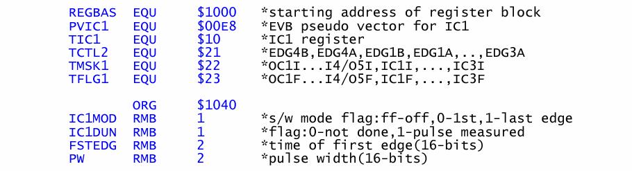
21 Example program (input Capture) Period Measurement Example Code FIRST EQU $D DEFINE A 2-BYTE LOCATION TO STORE FIRST EDGE PERIOD EQU $D2 DEFINE A 2-BYTE LOCATION TO STORE PERIOD ORG $C LDX #$ LDAA #$ STAA $2 EDGE DETECTION FOR IC SET TO RISING EDGES LDAA #$4 STAA $23 CLEARS ANY OLD FLAGS FROM ICF LOOP BRCLR $23,X #$4 LOOP LOOP HERE UNTIL FIRST RISING EDGE IS DETECTED LDD $ READ TIME OF FIRST CAPTURE STD FIRST STORE FIRST CAPTURE VALUE LDAA #$4 STAA $23 CLEAR THE ICF FLAG BEFORE NEXT EDGE LOOP2 BRCLR $23,X #$4 LOOP2 LOOP HERE UNTIL NEXT RISING EDGE IS DETECTED LDD $ READ TIME OF SECOND CAPTURE SUBD FIRST FIND THE TIME DIFFERENCE BEWTEEN EDGES STD PERIOD STORE THE RESULT AS THE PERIOD :
22 Real-Time Interrupt Generates hardware interrupts at a fixed rate Free-running counter cannot be interrupted One of four rates- software selected One flag- set at the user determined rate Flag must be cleared after it is used, especially when using interrupts or a system lock up will occur. RTI Registers TMSK2 $24 Real-Time Interrupt Enable TFLG2 $25 Real-Time Interrupt Flag PACTL $26 Real-Time Interrupt Rate Selects B6 RTII B6 RTIF B RTR B RTR
23 Real-Time Interrupt Rate Selects For 8MHz Crystal Frequency (2MHz E Clock) RTR RTR E/2 3 Divided By Nominal RTI Rate 4. ms ms ms ms RTI Example: Oven Control Example:Using a 33 ms RTI interrupt, the slave board should measure the oven temperature and save the value in a global variable. It should turn the heater on if the oven temperature is below the set point, and turn the heater off if the oven temperature is above the set point.
24 Pulse Accumulator Overview 8-bit Counter Incremented by edge on pin Used to measure duration of pulse number of events Key Things to Know Can be read or written at any time 2 Modes Event Counter Gated Time Accumulation PAI Pin: Port A Pin 7 Registers
25 Pulse Accumulator Associated Registers TMSK2 TOI RTII PAOVI PAII PR PR $24 TFLG2 TOF RTIF PAOVF PAIF $25 PACTL DDRA7 PAEN PAMOD PEDGE DDRA3 I4/O5 RTR RTR $26 b7 b PACNT $27 DDRA7: =input, =output. (normally configured as input when PA is used) PAEN: =PA disabled, =PA enabled PAMOD: =event counter, =gated time accumulation PEDGE event counter: =PA responds to falling edges, = rising edge gated time: =inhibit gate level is zero, =inhibit gate level is one PAOVI, PAOVF: PA overflow interrupt enable and flag PAII, PAIF: PA input edge interrupt enable and flag Pulse Accumulator Event Counting Mode Events must be translated into rising/falling edges on PAI to be counted PAMOD=, counts active edge of PAI Can cause interrupts after N events writing N s 2 s compliment to PACNT Can count more than 256 events by tracking the number of overflows. Example: a work piece counter on an assembly line can be realized using a light emitter/detector pair.
26 Event Counting Mode PAMOD= Counts Active Edge of PAI pin PA7/ PAI/ OC 8-BIT COUNTER PACNT Example: (PACNT=;PAEN=;PEDGE=) PAI PACNT Value Pulse Accumulator Gate Time Accumulation Mode PACNT increments every 64 th E-clock cycle when PAI pin is active. PAMOD=, PEDGE controls the inhibiting PAI pin level Can be used to accumulate the total time the pin was active over a series of pulses A common use is to measure pulse width (easier than using IC) Interrupt function: Overflow interrupt is useful in generating signals longer than the 8- bit counter range PAI edge interrupt is useful for signaling the end of a timing period
27 Gated Time Accumulation Mode PAMOD= Free-running E-clock divided by 64 Subject to PAI pin being active E/64 CLOCK (from Main Timer) Clock PA7/ PAI/ OC AND 8-BIT COUNTER PACNT Gated Time Example PACNT=;PAEN=;PEDGE= PEDGE= means inhibit gate is (inhibit counting when PAI is ) E/64 PAI PACNT Value
28 Pulse Accumulator Example: Generate interrupt at specified time Using gated time accumulation (PAMOD=) to set pulse accumulator to interrupt after 5ms Calculate time for one E/64 cycle Divide delay by time for one E/64 cycle Take 2 s complement and store in PACNT When input goes to active level, counter will increment until overflow Pulse Width Measurement Common use of Gated mode Measure duration of single pulses Easier than with Input Capture Counter is zero before pulse starts Pulse time is directly read after rising edge of pulse (need starting and ending count for input capture)
29 Assembly Code: Initialization to Count Negative Edges LDAA #BIT54HI STAA TFLG2 /*Clear previous interrupts*/ LDAA TMSK2 ORAA #BIT54HI /*Enable pulse accumulator interrupts*/ STAA TMSK2 LDAA PACTL ANDA #BIT7_4LO /*BIT7_4LO = % */ ORAA #BIT6HI STAA PACTL /*Select Event,Falling Edge,DDRA7- Input*/ References. M68HC E Series Technical Data 2. M68HC Reference Manual 3. Introduction to Mechatronics and Measurement Systems David G. Alciatore, Michael b. Histand 4. Software and Hardware Engineering Motorola M68HC Frederick M. Cady Questions?
COSC3215. Input Capture Output Compare
 COSC3215 Input Capture Output Compare Time Base A 16-bit free running counter is used as a time base for the IC/OC system. CLK0 CLK1 4:1 MUX Timer Clock TIMCLK PACK/256 PACK/65536 PACK PCLK CLK1 CLK0 Action
o The 9S12 has a 16-bit free-running counter to determine the time and event happens, and to make an event happen at a particular time
 More on Programming the 9S12 in C Huang Sections 5.2 through 5.4 Introduction to the 9S12 Hardware Subsystems Huang Sections 8.2-8.6 ECT_16B8C Block User Guide A summary of 9S12 hardware subsystems Introduction
Point System (for instructor and TA use only)
") EEL 4744C - Drs. George and Gugel Spring Semester 2002 Final Exam NAME SS# Closed book and closed notes examination to be done in pencil. Calculators are permitted. All work and solutions are to be written
EEL 4744C - Drs. George and Gugel Spring Semester 2002 Final Exam NAME SS# Closed book and closed notes examination to be done in pencil. Calculators are permitted. All work and solutions are to be written
RS flip-flop using NOR gate
 RS flip-flop using NOR gate Triggering and triggering methods Triggering : Applying train of pulses, to set or reset the memory cell is known as Triggering. Triggering methods:- There are basically two
Digital Systems Based on Principles and Applications of Electrical Engineering/Rizzoni (McGraw Hill
 Digital Systems Based on Principles and Applications of Electrical Engineering/Rizzoni (McGraw Hill Objectives: Analyze the operation of sequential logic circuits. Understand the operation of digital counters.
Figure 30.1a Timing diagram of the divide by 60 minutes/seconds counter
 Digital Clock The timing diagram figure 30.1a shows the time interval t 6 to t 11 and t 19 to t 21. At time interval t 9 the units counter counts to 1001 (9) which is the terminal count of the 74x160 decade
Menu. 68HC12 Timer Block Diagram EEL 3744 EEL Input Capture (IC)
") Intro to Input Capture Input Capture Programming Example >Measure the Elapsed time between Events Another Input Capture Programming Example >Detect a Signal Pattern XMEGA Input Capture Menu Look into my...
Intro to Input Capture Input Capture Programming Example >Measure the Elapsed time between Events Another Input Capture Programming Example >Detect a Signal Pattern XMEGA Input Capture Menu Look into my...
EMT 125 Digital Electronic Principles I CHAPTER 6 : FLIP-FLOP
 EMT 125 Digital Electronic Principles I CHAPTER 6 : FLIP-FLOP 1 Chapter Overview Latches Gated Latches Edge-triggered flip-flops Master-slave flip-flops Flip-flop operating characteristics Flip-flop applications
ELE2120 Digital Circuits and Systems. Tutorial Note 8
 ELE2120 Digital Circuits and Systems Tutorial Note 8 Outline 1. Register 2. Counters 3. Synchronous Counter 4. Asynchronous Counter 5. Sequential Circuit Design Overview 1. Register Applications: temporally
EKT 121/4 ELEKTRONIK DIGIT 1
 EKT 2/4 ELEKTRONIK DIGIT Kolej Universiti Kejuruteraan Utara Malaysia Sequential Logic Circuits - COUNTERS - LATCHES (review) S-R R Latch S-R R Latch Active-LOW input INPUTS OUTPUTS S R Q Q COMMENTS Q
Introduction to Sequential Circuits
 Introduction to Sequential Circuits COE 202 Digital Logic Design Dr. Muhamed Mudawar King Fahd University of Petroleum and Minerals Presentation Outline Introduction to Sequential Circuits Synchronous
Decade Counters Mod-5 counter: Decade Counter:
 Decade Counters We can design a decade counter using cascade of mod-5 and mod-2 counters. Mod-2 counter is just a single flip-flop with the two stable states as 0 and 1. Mod-5 counter: A typical mod-5
Digital Fundamentals: A Systems Approach
 Digital Fundamentals: A Systems Approach Counters Chapter 8 A System: Digital Clock Digital Clock: Counter Logic Diagram Digital Clock: Hours Counter & Decoders Finite State Machines Moore machine: One
Chapter 4. Logic Design
 Chapter 4 Logic Design 4.1 Introduction. In previous Chapter we studied gates and combinational circuits, which made by gates (AND, OR, NOT etc.). That can be represented by circuit diagram, truth table
IT T35 Digital system desigm y - ii /s - iii
 UNIT - III Sequential Logic I Sequential circuits: latches flip flops analysis of clocked sequential circuits state reduction and assignments Registers and Counters: Registers shift registers ripple counters
Other Flip-Flops. Lecture 27 1
 Other Flip-Flops Other types of flip-flops can be constructed by using the D flip-flop and external logic. Two flip-flops less widely used in the design of digital systems are the JK and T flip-flops.
CSE Latches and Flip-flops Dr. Izadi. NOR gate property: A B Z Cross coupled NOR gates: S M S R Q M
 CSE-4523 Latches and Flip-flops Dr. Izadi NOR gate property: A B Z A B Z Cross coupled NOR gates: S M S R M R S M R S R S R M S S M R R S ' Gate R Gate S R S G R S R (t+) S G R Flip_flops:. S-R flip-flop
MUHAMMAD NAEEM LATIF MCS 3 RD SEMESTER KHANEWAL
 1. A stage in a shift register consists of (a) a latch (b) a flip-flop (c) a byte of storage (d) from bits of storage 2. To serially shift a byte of data into a shift register, there must be (a) one click
Counters
 Counters A counter is the most versatile and useful subsystems in the digital system. A counter driven by a clock can be used to count the number of clock cycles. Since clock pulses occur at known intervals,
Tutorial Introduction
 Tutorial Introduction PURPOSE - To explain how to configure and use the in common applications OBJECTIVES: - Identify the steps to set up and configure the. - Identify techniques for maximizing the accuracy
Registers and Counters
 Registers and Counters Clocked sequential circuit = F/Fs and combinational gates Register Group of flip-flops (share a common clock and capable of storing one bit of information) Consist of a group of
YEDITEPE UNIVERSITY DEPARTMENT OF COMPUTER ENGINEERING. EXPERIMENT VIII: FLIP-FLOPS, COUNTERS 2014 Fall
 YEDITEPE UNIVERSITY DEPARTMENT OF COMPUTER ENGINEERING EXPERIMENT VIII: FLIP-FLOPS, COUNTERS 2014 Fall Objective: - Dealing with the operation of simple sequential devices. Learning invalid condition in
RS flip-flop using NOR gate
 RS flip-flop using NOR gate Triggering and triggering methods Triggering : Applying train of pulses, to set or reset the memory cell is known as Triggering. Triggering methods:- There are basically two
Experiment 8 Introduction to Latches and Flip-Flops and registers
 Experiment 8 Introduction to Latches and Flip-Flops and registers Introduction: The logic circuits that have been used until now were combinational logic circuits since the output of the device depends
DIGITAL SYSTEM FUNDAMENTALS (ECE421) DIGITAL ELECTRONICS FUNDAMENTAL (ECE422) COUNTERS
 DIGITAL ELECTRONICS FUNDAMENTAL (ECE422) COUNTERS") COURSE / CODE DIGITAL SYSTEM FUNDAMENTALS (ECE421) DIGITAL ELECTRONICS FUNDAMENTAL (ECE422) COUNTERS One common requirement in digital circuits is counting, both forward and backward. Digital clocks and
COURSE / CODE DIGITAL SYSTEM FUNDAMENTALS (ECE421) DIGITAL ELECTRONICS FUNDAMENTAL (ECE422) COUNTERS One common requirement in digital circuits is counting, both forward and backward. Digital clocks and
Counter/timer 2 of the 83C552 microcontroller
 INTODUCTION TO THE 83C552 The 83C552 is an 80C51 derivative with several extended features: 8k OM, 256 bytes AM, 10-bit A/D converter, two PWM channels, two serial I/O channels, six 8-bit I/O ports, and
Experiment # 9. Clock generator circuits & Counters. Digital Design LAB
 Digital Design LAB Islamic University Gaza Engineering Faculty Department of Computer Engineering Fall 2012 ECOM 2112: Digital Design LAB Eng: Ahmed M. Ayash Experiment # 9 Clock generator circuits & Counters
ASYNCHRONOUS COUNTER CIRCUITS
 ASYNCHRONOUS COUNTER CIRCUITS Asynchronous counters do not have a common clock that controls all the Hipflop stages. The control clock is input into the first stage, or the LSB stage of the counter. The
Sequential Digital Design. Laboratory Manual. Experiment #7. Counters
 The Islamic University of Gaza Engineering Faculty Department of Computer Engineering Spring 2018 ECOM 2022 Khaleel I. Shaheen Sequential Digital Design Laboratory Manual Experiment #7 Counters Objectives
Flip-Flops. Because of this the state of the latch may keep changing in circuits with feedback as long as the clock pulse remains active.
 Flip-Flops Objectives The objectives of this lesson are to study: 1. Latches versus Flip-Flops 2. Master-Slave Flip-Flops 3. Timing Analysis of Master-Slave Flip-Flops 4. Different Types of Master-Slave
Digital Logic Design Sequential Circuits. Dr. Basem ElHalawany
 Digital Logic Design Sequential Circuits Dr. Basem ElHalawany Combinational vs Sequential inputs X Combinational Circuits outputs Z A combinational circuit: At any time, outputs depends only on inputs
Microcontrollers. Outline. Class 4: Timer/Counters. March 28, Timer/Counter Introduction. Timers as a Timebase.
 Microcontrollers Class 4: Timer/Counters March 28, 2011 Outline Timer/Counter Introduction Timers as a Timebase Timers for PWM Outline Timer/Counter Introduction Timers as a Timebase Timers for PWM Outline
Lecture 8: Sequential Logic
 Lecture 8: Sequential Logic Last lecture discussed how we can use digital electronics to do combinatorial logic we designed circuits that gave an immediate output when presented with a given set of inputs
LATCHES & FLIP-FLOP. Chapter 7
 LATCHES & FLIP-FLOP Chapter 7 INTRODUCTION Latch and flip flops are categorized as bistable devices which have two stable states,called SET and RESET. They can retain either of this states indefinitely
EKT 121/4 ELEKTRONIK DIGIT 1
 EKT 121/4 ELEKTRONIK DIGIT 1 Kolej Universiti Kejuruteraan Utara Malaysia Bistable Storage Devices and Related Devices Introduction Latches and flip-flops are the basic single-bit memory elements used
Lab #10: Building Output Ports with the 6811
 1 Tiffany Q. Liu April 11, 2011 CSC 270 Lab #10 Lab #10: Building Output Ports with the 6811 Introduction The purpose of this lab was to build a 1-bit as well as a 2-bit output port with the 6811 training
Registers and Counters
 Registers and Counters Clocked sequential circuit = F/Fs and combinational gates Register Group of flip-flops (share a common clock and capable of storing one bit of information) Consist of a group of
2. Counter Stages or Bits output bits least significant bit (LSB) most significant bit (MSB) 3. Frequency Division 4. Asynchronous Counters
 most significant bit (MSB) 3. Frequency Division 4. Asynchronous Counters") 2. Counter Stages or Bits The number of output bits of a counter is equal to the flip-flop stages of the counter. A MOD-2 n counter requires n stages or flip-flops in order to produce a count sequence
2. Counter Stages or Bits The number of output bits of a counter is equal to the flip-flop stages of the counter. A MOD-2 n counter requires n stages or flip-flops in order to produce a count sequence
Chapter. Synchronous Sequential Circuits
 Chapter 5 Synchronous Sequential Circuits Logic Circuits- Review Logic Circuits 2 Combinational Circuits Consists of logic gates whose outputs are determined from the current combination of inputs. Performs
CHAPTER 4: Logic Circuits
 CHAPTER 4: Logic Circuits II. Sequential Circuits Combinational circuits o The outputs depend only on the current input values o It uses only logic gates, decoders, multiplexers, ALUs Sequential circuits
TV Synchronism Generation with PIC Microcontroller
 TV Synchronism Generation with PIC Microcontroller With the widespread conversion of the TV transmission and coding standards, from the early analog (NTSC, PAL, SECAM) systems to the modern digital formats
ECE 263 Digital Systems, Fall 2015
 ECE 263 Digital Systems, Fall 2015 REVIEW: FINALS MEMORY ROM, PROM, EPROM, EEPROM, FLASH RAM, DRAM, SRAM Design of a memory cell 1. Draw circuits and write 2 differences and 2 similarities between DRAM
CHAPTER 4: Logic Circuits
 CHAPTER 4: Logic Circuits II. Sequential Circuits Combinational circuits o The outputs depend only on the current input values o It uses only logic gates, decoders, multiplexers, ALUs Sequential circuits
CHAPTER 6 COUNTERS & REGISTERS
 CHAPTER 6 COUNTERS & REGISTERS 6.1 Asynchronous Counter 6.2 Synchronous Counter 6.3 State Machine 6.4 Basic Shift Register 6.5 Serial In/Serial Out Shift Register 6.6 Serial In/Parallel Out Shift Register
Logic Gates, Timers, Flip-Flops & Counters. Subhasish Chandra Assistant Professor Department of Physics Institute of Forensic Science, Nagpur
 Logic Gates, Timers, Flip-Flops & Counters Subhasish Chandra Assistant Professor Department of Physics Institute of Forensic Science, Nagpur Logic Gates Transistor NOT Gate Let I C be the collector current.
Introduction. NAND Gate Latch. Digital Logic Design 1 FLIP-FLOP. Digital Logic Design 1
 2007 Introduction BK TP.HCM FLIP-FLOP So far we have seen Combinational Logic The output(s) depends only on the current values of the input variables Here we will look at Sequential Logic circuits The
Logic and Computer Design Fundamentals. Chapter 7. Registers and Counters
 Logic and Computer Design Fundamentals Chapter 7 Registers and Counters Registers Register a collection of binary storage elements In theory, a register is sequential logic which can be defined by a state
Analog Input & Output
 EEL 4744C: Microprocessor Applications Lecture 10 Part 1 Analog Input & Output Dr. Tao Li 1 Read Assignment M&M: Chapter 11 Dr. Tao Li 2 To process continuous signals as functions of time Advantages free
Introduction to Mechatronics. Fall Instructor: Professor Charles Ume. Analog to Digital Converter
 ME6405 Introduction to Mechatronics Fall 2006 Instructor: Professor Charles Ume Analog to Digital Converter Analog and Digital Signals Analog signals have infinite states available mercury thermometer
The part chosen for the encoder was the Hamatsu P5587 photoreflector. The device
 Description of Shaft Encoder Construction and Testing Louis Brandy The part chosen for the encoder was the Hamatsu P5587 photoreflector. The device consists of an IR emitter and a phototransistor pair.
Advanced Devices. Registers Counters Multiplexers Decoders Adders. CSC258 Lecture Slides Steve Engels, 2006 Slide 1 of 20
 Advanced Devices Using a combination of gates and flip-flops, we can construct more sophisticated logical devices. These devices, while more complex, are still considered fundamental to basic logic design.
Name Of The Experiment: Sequential circuit design Latch, Flip-flop and Registers
 EEE 304 Experiment No. 07 Name Of The Experiment: Sequential circuit design Latch, Flip-flop and Registers Important: Submit your Prelab at the beginning of the lab. Prelab 1: Construct a S-R Latch and
Logic Design. Flip Flops, Registers and Counters
 Logic Design Flip Flops, Registers and Counters Introduction Combinational circuits: value of each output depends only on the values of inputs Sequential Circuits: values of outputs depend on inputs and
UNIVERSITI TEKNOLOGI MALAYSIA
 SULIT Faculty of Computing UNIVERSITI TEKNOLOGI MALAYSIA FINAL EXAMINATION SEMESTER I, 2016 / 2017 SUBJECT CODE : SUBJECT NAME : SECTION : TIME : DATE/DAY : VENUES : INSTRUCTIONS : Answer all questions
Asynchronous (Ripple) Counters
 Counters") Circuits for counting events are frequently used in computers and other digital systems. Since a counter circuit must remember its past states, it has to possess memory. The chapter about flip-flops introduced
Circuits for counting events are frequently used in computers and other digital systems. Since a counter circuit must remember its past states, it has to possess memory. The chapter about flip-flops introduced
FLIP-FLOPS AND RELATED DEVICES
 C H A P T E R 5 FLIP-FLOPS AND RELATED DEVICES OUTLINE 5- NAND Gate Latch 5-2 NOR Gate Latch 5-3 Troubleshooting Case Study 5-4 Digital Pulses 5-5 Clock Signals and Clocked Flip-Flops 5-6 Clocked S-R Flip-Flop
Flip Flop. S-R Flip Flop. Sequential Circuits. Block diagram. Prepared by:- Anwar Bari
 Sequential Circuits The combinational circuit does not use any memory. Hence the previous state of input does not have any effect on the present state of the circuit. But sequential circuit has memory
Synchronous Sequential Logic
 Synchronous Sequential Logic Ranga Rodrigo August 2, 2009 1 Behavioral Modeling Behavioral modeling represents digital circuits at a functional and algorithmic level. It is used mostly to describe sequential
Rangkaian Sekuensial. Flip-flop
 Rangkaian Sekuensial Rangkaian Sekuensial Flip-flop Combinational versus Sequential Functions Logic functions are categorized as being either combinational (sometimes referred to as combinatorial) or sequential.
Electrical & Computer Engineering ECE 491. Introduction to VLSI. Report 1
 Electrical & Computer Engineering ECE 491 Introduction to VLSI Report 1 Marva` Morrow INTRODUCTION Flip-flops are synchronous bistable devices (multivibrator) that operate as memory elements. A bistable
Last time, we saw how latches can be used as memory in a circuit
 Flip-Flops Last time, we saw how latches can be used as memory in a circuit Latches introduce new problems: We need to know when to enable a latch We also need to quickly disable a latch In other words,
Flip-Flops and Sequential Circuit Design
 Flip-Flops and Sequential Circuit Design ECE 52 Summer 29 Reading ssignment Brown and Vranesic 7 Flip-Flops, Registers, Counters and a Simple Processor 7.5 T Flip-Flop 7.5. Configurable Flip-Flops 7.6
Slide 1. Flip-Flops. Cross-NOR SR flip-flop S R Q Q. hold reset set not used. Cross-NAND SR flip-flop S R Q Q. not used reset set hold 1 Q.
 Slide Flip-Flops Cross-NOR SR flip-flop Reset Set Cross-NAND SR flip-flop Reset Set S R reset set not used S R not used reset set 6.7 Digital ogic Slide 2 Clocked evel-triggered NAND SR Flip-Flop S R SR
CS 110 Computer Architecture. Finite State Machines, Functional Units. Instructor: Sören Schwertfeger.
 CS 110 Computer Architecture Finite State Machines, Functional Units Instructor: Sören Schwertfeger http://shtech.org/courses/ca/ School of Information Science and Technology SIST ShanghaiTech University
SEQUENTIAL LOGIC. Satish Chandra Assistant Professor Department of Physics P P N College, Kanpur
 SEQUENTIAL LOGIC Satish Chandra Assistant Professor Department of Physics P P N College, Kanpur www.satish0402.weebly.com OSCILLATORS Oscillators is an amplifier which derives its input from output. Oscillators
EET2411 DIGITAL ELECTRONICS
 5-8 Clocked D Flip-FlopFlop One data input. The output changes to the value of the input at either the positive going or negative going clock trigger. May be implemented with a J-K FF by tying the J input
Digital Circuits 4: Sequential Circuits
 Digital Circuits 4: Sequential Circuits Created by Dave Astels Last updated on 2018-04-20 07:42:42 PM UTC Guide Contents Guide Contents Overview Sequential Circuits Onward Flip-Flops R-S Flip Flop Level
Chapter 6. Flip-Flops and Simple Flip-Flop Applications
 Chapter 6 Flip-Flops and Simple Flip-Flop Applications Basic bistable element It is a circuit having two stable conditions (states). It can be used to store binary symbols. J. C. Huang, 2004 Digital Logic
NH 67, Karur Trichy Highways, Puliyur C.F, Karur District UNIT-III SEQUENTIAL CIRCUITS
 NH 67, Karur Trichy Highways, Puliyur C.F, 639 114 Karur District DEPARTMENT OF ELETRONICS AND COMMUNICATION ENGINEERING COURSE NOTES SUBJECT: DIGITAL ELECTRONICS CLASS: II YEAR ECE SUBJECT CODE: EC2203
DEPARTMENT OF COMPUTER SCIENCE & ENGINEERING
 DRONACHARYA GROUP OF INSTITUTIONS, GREATER NOIDA Affiliated to Mahamaya Technical University, Noida Approved by AICTE DEPARTMENT OF COMPUTER SCIENCE & ENGINEERING Lab Manual for Computer Organization Lab
CPE 200L LABORATORY 3: SEQUENTIAL LOGIC CIRCUITS UNIVERSITY OF NEVADA, LAS VEGAS GOALS: BACKGROUND: SR FLIP-FLOP/LATCH
 CPE 200L LABORATORY 3: SEUENTIAL LOGIC CIRCUITS DEPARTMENT OF ELECTRICAL AND COMPUTER ENGINEERING UNIVERSITY OF NEVADA, LAS VEGAS GOALS: Learn to use Function Generator and Oscilloscope on the breadboard.
Logic Devices for Interfacing, The 8085 MPU Lecture 4
 Logic Devices for Interfacing, The 8085 MPU Lecture 4 1 Logic Devices for Interfacing Tri-State devices Buffer Bidirectional Buffer Decoder Encoder D Flip Flop :Latch and Clocked 2 Tri-state Logic Outputs
Chapter 8 Sequential Circuits
 Philadelphia University Faculty of Information Technology Department of Computer Science Computer Logic Design By 1 Chapter 8 Sequential Circuits 1 Classification of Combinational Logic 3 Sequential circuits
1. Convert the decimal number to binary, octal, and hexadecimal.
 1. Convert the decimal number 435.64 to binary, octal, and hexadecimal. 2. Part A. Convert the circuit below into NAND gates. Insert or remove inverters as necessary. Part B. What is the propagation delay
Analogue Versus Digital [5 M]
![Analogue Versus Digital [5 M]](/thumbs/93/111640168.jpg "Analogue Versus Digital [5 M]") Q.1 a. Analogue Versus Digital [5 M] There are two basic ways of representing the numerical values of the various physical quantities with which we constantly deal in our day-to-day lives. One of the ways,
Q.1 a. Analogue Versus Digital [5 M] There are two basic ways of representing the numerical values of the various physical quantities with which we constantly deal in our day-to-day lives. One of the ways,
Chapter 5 Flip-Flops and Related Devices
 Chapter 5 Flip-Flops and Related Devices Chapter 5 Objectives Selected areas covered in this chapter: Constructing/analyzing operation of latch flip-flops made from NAND or NOR gates. Differences of synchronous/asynchronous
VTU NOTES QUESTION PAPERS NEWS RESULTS FORUMS Registers
 Registers Registers are a very important digital building block. A data register is used to store binary information appearing at the output of an encoding matrix.shift registers are a type of sequential
Read-only memory (ROM) Digital logic: ALUs Sequential logic circuits. Don't cares. Bus
 Digital logic: ALUs Sequential logic circuits. Don't cares. Bus") Digital logic: ALUs Sequential logic circuits CS207, Fall 2004 October 11, 13, and 15, 2004 1 Read-only memory (ROM) A form of memory Contents fixed when circuit is created n input lines for 2 n addressable
Digital logic: ALUs Sequential logic circuits CS207, Fall 2004 October 11, 13, and 15, 2004 1 Read-only memory (ROM) A form of memory Contents fixed when circuit is created n input lines for 2 n addressable
Review of digital electronics. Storage units Sequential circuits Counters Shifters
 Review of digital electronics Storage units Sequential circuits ounters Shifters ounting in Binary A counter can form the same pattern of 0 s and 1 s with logic levels. The first stage in the counter represents
Chapter 4: One-Shots, Counters, and Clocks
 Chapter 4: One-Shots, Counters, and Clocks I. The Monostable Multivibrator (One-Shot) The timing pulse is one of the most common elements of laboratory electronics. Pulses can control logical sequences
Asynchronous Counter
 Asynchronous Counter Contents: Asynchronous/Ripple Counter Propagation Delay in Ripple Counter MOD Number Synchronous/Parallel Counter 10101010101010101010101010101010101010101010101010101010101010101010101010101010
MODULE 3. Combinational & Sequential logic
 MODULE 3 Combinational & Sequential logic Combinational Logic Introduction Logic circuit may be classified into two categories. Combinational logic circuits 2. Sequential logic circuits A combinational
UNIT-3: SEQUENTIAL LOGIC CIRCUITS
 UNIT-3: SEQUENTIAL LOGIC CIRCUITS STRUCTURE 3. Objectives 3. Introduction 3.2 Sequential Logic Circuits 3.2. NAND Latch 3.2.2 RS Flip-Flop 3.2.3 D Flip-Flop 3.2.4 JK Flip-Flop 3.2.5 Edge Triggered RS Flip-Flop
Long and Fast Up/Down Counters Pushpinder Kaur CHOUHAN 6 th Jan, 2003
 1 Introduction Long and Fast Up/Down Counters Pushpinder Kaur CHOUHAN 6 th Jan, 2003 Circuits for counting both forward and backward events are frequently used in computers and other digital systems. Digital
QUICK GUIDE COMPUTER LOGICAL ORGANIZATION - OVERVIEW
 QUICK GUIDE http://www.tutorialspoint.com/computer_logical_organization/computer_logical_organization_quick_guide.htm COMPUTER LOGICAL ORGANIZATION - OVERVIEW Copyright tutorialspoint.com In the modern
Final Exam review: chapter 4 and 5. Supplement 3 and 4
 Final Exam review: chapter 4 and 5. Supplement 3 and 4 1. A new type of synchronous flip-flop has the following characteristic table. Find the corresponding excitation table with don t cares used as much
Today 3/8/11 Lecture 8 Sequential Logic, Clocks, and Displays
 Today 3/8/ Lecture 8 Sequential Logic, Clocks, and Displays Flip Flops and Ripple Counters One Shots and Timers LED Displays, Decoders, and Drivers Homework XXXX Reading H&H sections on sequential logic
Name: Date: Suggested Reading Chapter 7, Digital Systems, Principals and Applications; Tocci
 Richland College Engineering Technology Rev. 0 B. Donham Rev. 1 (7/2003) J. Horne Rev. 2 (1/2008) J. Bradbury Digital Fundamentals CETT 1425 Lab 7 Asynchronous Ripple Counters Name: Date: Objectives: To
Counter dan Register
 Counter dan Register Introduction Circuits for counting events are frequently used in computers and other digital systems. Since a counter circuit must remember its past states, it has to possess memory.
Sequential Logic and Clocked Circuits
 Sequential Logic and Clocked Circuits Clock or Timing Device Input Variables State or Memory Element Combinational Logic Elements From combinational logic, we move on to sequential logic. Sequential logic
Vignana Bharathi Institute of Technology UNIT 4 DLD
 DLD UNIT IV Synchronous Sequential Circuits, Latches, Flip-flops, analysis of clocked sequential circuits, Registers, Shift registers, Ripple counters, Synchronous counters, other counters. Asynchronous
Digital Circuit And Logic Design I. Lecture 8
 Digital Circuit And Logic Design I Lecture 8 Outline Sequential Logic Design Principles (1) 1. Introduction 2. Latch and Flip-flops 3. Clocked Synchronous State-Machine Analysis Panupong Sornkhom, 2005/2
Digital Circuit And Logic Design I
 Digital Circuit And Logic Design I Lecture 8 Outline Sequential Logic Design Principles (1) 1. Introduction 2. Latch and Flip-flops 3. Clocked Synchronous State-Machine Panupong Sornkhom, 2005/2 2 1 Sequential
Synchronous sequential circuits
 8.6.5 Synchronous sequential Table of content. Combinational circuit design. Elementary combinatorial for data transmission. Memory structures 4. Programmable logic devices 5. Algorithmic minimization
Chapter 2. Digital Circuits
 Chapter 2. Digital Circuits Logic gates Flip-flops FF registers IC registers Data bus Encoders/Decoders Multiplexers Troubleshooting digital circuits Most contents of this chapter were covered in 88-217
Chapter 5 Sequential Circuits
 Logic and Computer Design Fundamentals Chapter 5 Sequential Circuits Part 2 Sequential Circuit Design Charles Kime & Thomas Kaminski 28 Pearson Education, Inc. (Hyperlinks are active in View Show mode)
Latches, Flip-Flops, and Registers. Dr. Ouiem Bchir
 Latches, Flip-Flops, and Registers (Chapter #7) Dr. Ouiem Bchir The slides included herein were taken from the materials accompanying Fundamentals of Logic Design, 6 th Edition, by Roth and Kinney. Sequential
Unit 11. Latches and Flip-Flops
 Unit 11 Latches and Flip-Flops 1 Combinational Circuits A combinational circuit consists of logic gates whose outputs, at any time, are determined by combining the values of the inputs. For n input variables,
Chapter 6 Registers and Counters
 EEA051 - Digital Logic 數位邏輯 Chapter 6 Registers and Counters 吳俊興國立高雄大學資訊工程學系 January 2006 Chapter 6 Registers and Counters 6-1 Registers 6-2 Shift Registers 6-3 Ripple Counters 6-4 Synchronous Counters