R&S RTM Digital Oscilloscope Scope of the art
|
|
|
- Charles Goodman
- 5 years ago
- Views:
Transcription


1 RTM_bro_en_ _v0600.indd 1 Product Brochure Test & Measurement R&S RTM Digital Oscilloscope Scope of the art :16:54

2 R&S RTM Digital Oscilloscope At a glance Ease of use combined with fast and reliable results is precisely what users get with the R&S RTM bench oscilloscope. While other oscilloscopes are still booting up, the R&S RTM is already displaying signals that would otherwise be lost in the noise, and evaluating results. All on one screen with two displays, with lightning fast functions. The R&S RTM models with 200 MHz, 350 MHz, 500 MHz or 1 GHz bandwidth offer a maximum sampling rate of 5 Gsample/s and a maximum memory depth of 20 Msample. As a result, they can display signals accurately, right down to the details, as well as provide high time resolution, even for long sequences. Besides the common measurement and analysis tools, R&S RTM oscilloscopes have special features that help users to achieve the desired results quickly during debugging and signal analysis. At the push of a button, the QuickMeas function graphically displays the key measurement values for the signal that is currently active and updates them continuously. Functions such as mask tests and video triggers are supplied as standard with the R&S RTM. As a true scope of the art, the R&S RTM meets the increased demands on bench oscilloscopes for the development, production and servicing of embedded hardware, providing time, frequency, protocol and logic analysis, plus a digital voltmeter in a single box: Time analysis: high sensitivity of 1 mv/div to detect signals that would otherwise be lost in the noise Frequency analysis: reliable fault detection with integrated FFT and spectrum analysis with spectrogram option Logic analysis: 20 Msample with 5 Gsample/s for detailed analysis of digital signals Protocol analysis: simple triggering and decoding of serial buses Digital voltmeter/frequency counter: key signal parameters at a glance 2 RTM_bro_en_ _v0600.indd :16:55
3 R&S RTM Digital Oscilloscope Benefits and key features Results-oriented: fast and precise Fast time to results: turn on, measure and done Signal details at the push of a button: QuickMeas Settings in seconds: mask test Focus on details: search and navigation Integrated: FFT analysis In focus: digital voltmeter and frequency counter page 4 Accurate: down to the mv 1 mv/div: full measurement bandwidth Frontends: low noise and low crosstalk Deep memory: long sequences at high resolutions To the point: comprehensive triggering capabilities page 8 Usability: smart concepts Easy orientation: color-coded controls Two displays instead of one: VirtualScreen Error-tolerant: undo/redo function Remote control, data exchange: diverse interfaces Multilingual: choice of nine languages Extensible: more application power Logic analysis: fast and precise testing of embedded designs Serial protocols: easy triggering and decoding Segmented memory: 460 Msample with history function Power analysis: current and voltage in detail Spectrum analysis: quickly identifying interactions between time and frequency page 12 Probes: excellent contacting page 22 Accessories: for rack installation and transport page 25 Models Base unit R&S RTM2022 Bandwidth 200 MHz R&S RTM2024 R&S RTM MHz R&S RTM2104 digital (with R&S RTM-B1) Max. sampling rate Max. acquisition memory Mixed signal option (MSO; with R&S RTM-B1 option) 5 Gsample/s 20 Msample, 460 Msample segmented memory (optional) 400 MHz, 5 Gsample/s (max.), 20 Msample (max.) MHz R&S RTM2054 R&S RTM2102 analog 4 R&S RTM2034 R&S RTM2052 Channels GHz 2 4 Rohde & Schwarz R&S RTM Digital Oscilloscope 3 RTM_bro_en_ _v0600.indd :16:55

4 Results-oriented: fast and precise R&S RTM oscilloscopes provide a decisive edge when performing everyday measurement tasks, delivering more comprehensive results, faster. Measurement tools such as QuickMeas, mask test and math functions are supplied as standard. Fast time to results: turn on, measure and done Optimized for fast results, the R&S RTM starts up within only a few seconds. The most important measurement results for an active signal can be obtained at the push of a button (QuickMeas function), enabling fast signal characterization. Signal details at the push of a button: QuickMeas The QuickMeas function offered by the R&S RTM oscilloscopes is unique. At the push of a button, it displays the key measurement values for a currently active signal (see table). The signal is also graphically displayed with continuously updated auxiliary lines and markers. In addition to the QuickMeas results, the oscilloscopes also provide customary automatic measurement functions such as measurement of peak-to-peak voltage and signal frequency. The results are presented in tabular form, with statistical evaluation if desired. QuickMeas: key results at the push of a button Measurement value Display Vp+ positive peak voltage Vp negative peak voltage tr rise time tf fall time Mean mean voltage Vpp peak-to-peak voltage RMS RMS value T time f frequency graphic display directly on the waveform tabular display on the bottom right of the screen QuickMeas: automatic measurement and graphical display at the push of a button. 4 RTM_bro_en_ _v0600.indd :16:55


5 Measurement results in detail: cursor functions Settings in seconds: mask test The R&S RTM offers additional functions beyond the standard horizontal and vertical cursor measurements. Users can easily apply measurements such as mean voltage, RMS value and a pulse counter to a specific section of the signal. At the push of a button, the Set to Wave function automatically assigns the cursors to the corresponding signals, eliminating the need for manual positioning. Mask tests quickly reveal whether a specific signal lies within defined tolerance limits and use statistical pass/fail evaluation to assess the quality and stability of a device under test. Signal anomalies and unexpected results are easy to identify by stopping the measurement if the mask is violated. The mask test function is a standard feature in R&S RTM oscilloscopes. It is easy to use and can be flexibly configured. A new mask can be created from a reference signal with just a few keystrokes. Existing masks can be loaded from the internal memory or from a USB flash drive. If an active mask is violated, various actions can be taken to ensure the optimum response. Mask test functions Evaluation total number of acquired waveforms number of successful and faulty sweeps (absolute/percentage) total test duration Actions acoustic signal stop acquisition screenshot print save waveform output pulse Mask test: mask definition from a reference signal. Special cursor measurement: using three cursors to determine the duty cycle of a pulsed signal. Rohde & Schwarz R&S RTM Digital Oscilloscope 5 RTM_bro_en_ _v0600.indd :16:55

6 Focus on details: search and navigation Integrated: FFT analysis The sampling rate of up to 5 Gsample/s enables R&S RTM oscilloscopes to achieve a high time resolution. The memory depth of up to 20 Msample makes it possible to acquire long signal sequences, e.g. 4 ms at a sampling rate of 5 Gsample/s. The FFT function has a dedicated button and enables users to detect and analyze faults within a signal's spectrum. R&S RTM oscilloscopes simultaneously provide a spectral display of the signal and a time domain window for checking the sampling interval. The Autoset button is extremely convenient: when it is pressed, the instrument automatically selects the amplitude and frequency scaling that optimally matches the measured signal. The search and navigation function helps users to manage even long records, enabling them to detect and mark events within seconds. Users can search for simple signal characteristics such as edge and pulse width, complex bit sequences and decoded serial buses. A table lists the matching events and can be used to navigate from one event to another. Separate from the search function, users can set eight event markers on the signal and easily navigate through them using the Next and Prev buttons on the R&S RTM oscilloscopes. For detailed analysis, the zoom function can be used to enlarge the signal up to :1. The R&S RTM-K18 option (see page 20) turns the R&S RTM into a spectrum analyzer with spectrogram function. Search and navigation Types edge pulse width peak rise time fall time runt clock data pattern protocol contents Display diagram, table Markers up to 32 Navigation marker quick-select button rotary knob in table FFT analysis: fast identification of harmonics at the output voltage of a DC/ DC converter. 6 RTM_bro_en_ _v0600.indd :16:56

7 In focus: digital voltmeter and frequency counter Easy comparisons: four reference waveforms With the R&S RTM-K32 option, any channel can be used as a three-digit digital voltmeter (DVM) and as a seven- digit frequency counter. The measurement is performed regardless of the oscilloscope status, i.e. it will update even if the acquisition was stopped. When analyzing faults, it is useful to compare the waveforms against a reference. The R&S RTM provides up to four reference waveforms that can be generated at the press of a button. The waveforms can be scaled, stored internally or externally and reloaded. More than a calculator: math functions Math functions tailored to everyday problems help solve measurement problems quickly. For example, with just a few keystrokes users can square the voltage waveform and divide it by the resistance in order to directly display power over time. In addition to basic arithmetic operations, advanced functions such as derivatives and digital filters are available. The results can also be used as arguments for other math functions. Digital voltmeter modes AC RMS DC AC + DC RMS Crest factor Peak+ PeakPeak-to-peak Math functions Functions +,, *, / max./min. square (²), square root ( ) absolute value pos./neg. waveform inversion reciprocal log10, ln derivation, integration cycle, frequency pos./neg. duty cycle pos./neg. pulse width Digital filters lowpass/highpass Digital voltmeter and frequency counter. Rohde & Schwarz R&S RTM Digital Oscilloscope 7 RTM_bro_en_ _v0600.indd :16:56

8 Accurate: down to the mv Rohde & Schwarz has many years of experience developing precision test and measurement equipment and has brought this expertise to bear in the R&S RTM oscilloscopes. Users benefit from top accuracy and excellent analysis capabilities thanks to deep memory and a powerful trigger system. 1 mv/div: full measurement bandwidth With their input sensitivity of up to 1 mv/div, R&S RTM oscilloscopes offer high vertical resolution. Other oscilloscopes attain such high input sensitivity only by employing software-based zooming or by limiting the bandwidth. The R&S RTM shows a signal's real sampling points over the full measurement bandwidth, even at 1 mv/div. This high measurement accuracy is particularly beneficial when measuring small signal amplitudes. Frontends: low noise and low crosstalk The accuracy of a signal displayed on the screen greatly depends on the oscilloscope's inherent noise. R&S RTM oscilloscopes have low-noise frontends and A/D converters, enabling them to measure precisely, even at the smallest vertical resolutions. This precision is retained even when additional channels are used. The R&S RTM has an excellent channel-tochannel isolation of > 50 db up to 500 MHz, which ensures that the signal from one channel has the lowest possible influence on signals from the other channels. Acquisition period as a function of sampling rate and memory depth 10 ksample 1 Msample 10 Msample 20 Msample 5 Gsample/s 2 μs 200 μs 2000 μs 4000 μs 2.5 Gsample/s 4 μs 400 μs 4000 μs 8000 μs RMS: µv Vpp: µv Extremely low inherent noise, even for a vertical input sensitivity of 1 mv/div at full bandwidth and full resolution. 8 RTM_bro_en_ _v0600.indd :16:56

9 Deep memory: long sequences at high resolutions Trigger types Edge rising, falling, both LF, RF suppression, lowpass hysteresis: automatic, small, medium, large Pulse time: >, <, =, interval: inside, outside polarity: positive, negative Rise time polarity: rising, falling, both level: upper, lower time: >, <, =, Runt level: upper, lower polarity: positive, negative Video PAL, PAL-M, NTSC, SECAM, SDTV 576i, HDTV 720p, HDTV 1080p, HDTV 1080i signal: positive, negative lines frames: odd, even, all Logic pattern over analog and digital channels The more details an oscilloscope can show, the higher the probability of detecting signal faults and important events. The oscilloscope must have a high time resolution, i.e. a high sampling rate. In addition, many applications require long acquisition periods, for instance for analyzing transients or serial protocols. This is where R&S RTM oscilloscopes excel. They offer a deep memory of 20 Msample at a time resolution of up to 200 ps (5 Gsample/s sampling rate). When combined with the R&S RTM-K15 history and segmented memory option, the memory is expanded to 460 Msample. To the point: comprehensive triggering capabilities Precise triggering ensures a stable signal display on the screen and fast isolation of signal events of interest. R&S RTM oscilloscopes offer many standard trigger capabilities, including pulse width, runt and video triggers. Capabilities include complex trigger conditions with logical linking of analog and digital channels. Serial protocol triggers are optionally available. Dedicated buttons allow fast switching between the Auto and Normal triggers as well as selection of the trigger edge and source. The rotary knob for trigger level offers additional operating convenience: a single press sets the trigger level to 50 % of the signal amplitude. duration: >, <, =, interval: inside, outside, timeout Protocol (optional) content error B trigger edge Complex sequences are found quickly using the pattern trigger. Rohde & Schwarz R&S RTM Digital Oscilloscope 9 RTM_bro_en_ _v0600.indd :16:56

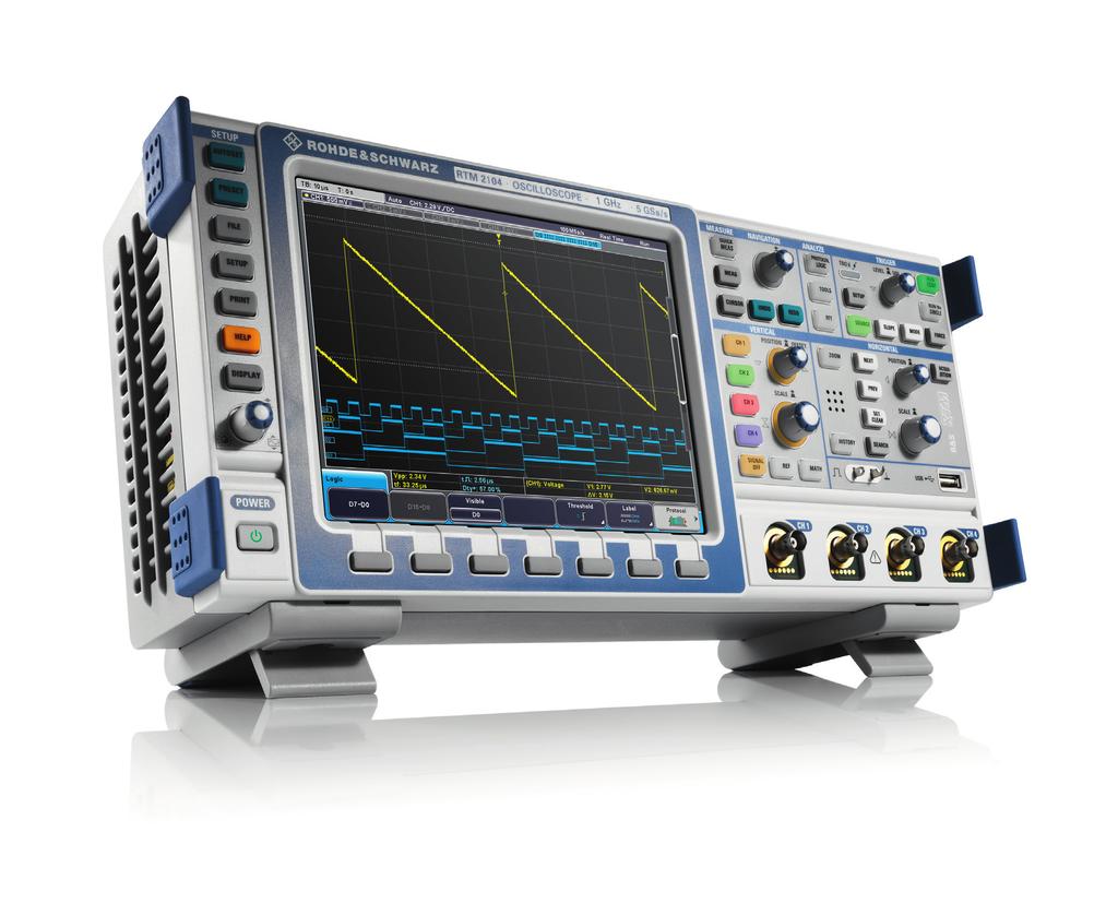
10 Overview of the R&S RTM oscilloscope Control elements LAN interface for remote control or for accessing the instrument via a web browser comes as standard. A GPIB interface is available as an option. The DVI output controls a monitor or a data projector. Extensive cursor-based measurement functions All instruments can be e xtended to 1 GHz Preset to return to default or user-defined settings Brilliant 8.4" XGA color display One-touch documentation: easily save screenshots and measurements Help: context-sensitive and always available Knob for setting the intensity of the waveforms Menus with flat structure for fast access Fluent in different l anguages such as German, English, French, Spanish, Russian, simplified and traditional Chinese, Korean and Japanese Quickly ready for use thanks to fast booting 10 RTM_bro_en_ _v0600.indd :16:57

11 Key measurement results at the push of a button Multilevel undo/redo function to easily restore previous settings Fast access to logic and protocol analysis Direct access to frequently required analysis functions Easy search and navigation between signal events USB port for data exchange, documentation or firmware updates Additional device and USB host ports on the rear side Color-coded controls indicate the currently selected channel Scrollable screen content VirtualScreen extends screen to 20 divisions for straightforward display of all signals History function for analysis of 460 Msample deep segmented memory Probe interface supports all Rohde & Schwarz probes Digital voltmeter and frequency counter can be activated on every channel Spectrum analysis and spectrogram on every channel Rohde & Schwarz R&S RTM Digital Oscilloscope 11 RTM_bro_en_ _v0600.indd :16:58

12 Extensible: more application power Investments in test and measurement equipment are subject to one all-important rule: the equipment must be capable of growing with user requirements. Rohde & Schwarz has optimized the R&S RTM to meet this demand. Availability without interruption: adaptable hardware With R&S RTM oscilloscopes, there is no need to return instruments for upgrades. Hardware options can be enabled with a keycode (e.g. logic analysis) or simply installed on site (e.g. GPIB interface), yielding the following benefits: Quick and easy installation of new options Instrument immediately ready for continued use No additional installation costs No additional expense for alignment or recalibration after installation of options Adaptable: software options on demand The base unit includes the complete functionality of an advanced oscilloscope but is extensible in steps. For example, analysis options are available for serial buses and power electronics. The R&S RTM keeps pace with the challenges that are sure to arise in any company. Simple and free of charge: firmware updates The instrument firmware is updated using a USB storage device. Free updates can be downloaded from the Internet at Higher bandwidth: upgrade including calibration All R&S RTM oscilloscope models can be upgraded to higher bandwidths as needed. The upgrade option includes complete testing and calibration of the instrument by Rohde & Schwarz at one of its service centers. Secure erase The secure erase function protects sensitive data. This central function removes all user data and settings, including device setups and reference waveforms. Options Bandwidth upgrade ple on-site process without shipping back the instrument. R&S RTM-B MHz to 500 MHz R&S RTM-B MHz to 1 GHz R&S RTM-B MHz to 500 MHz R&S RTM-B MHz to 1 GHz R&S RTM-B MHz to 1 GHz R&S RTM-B205 Logic analysis (MSO) R&S RTM-B1 GPIB Interface R&S RTM-B10 Serial triggering and decoding R&S RTM oscilloscopes: prepared for logic analysis. Installation is a sim- 200 MHz to 350 MHz I²C/SPI R&S RTM-K1 UART/RS-232/RS-422/ RS-485 R&S RTM-K2 CAN/LIN R&S RTM-K3 I²S/LJ/RJ/TDM R&S RTM-K5 MIL-STD-1553 R&S RTM-K6 ARINC 429 R&S RTM-K7 History and segmented memory R&S RTM-K15 Spectrum analysis and spectrogram R&S RTM-K18 Power analysis R&S RTM-K31 Digital voltmeter (DVM) R&S RTM-K32 12 RTM_bro_en_ _v0600.indd :17:00

13 Logic analysis: fast and precise testing of embedded designs The R&S RTM-B1 option turns the R&S RTM into an easy-to-use mixed signal oscilloscope (MSO) with 16 digital channels. Precision measurement: up to 5 Gsample/s sampling rate The R&S RTM oscilloscopes' sampling rate of up to 5 Gsample/s makes it possible to accurately measure the timing of logic signals. Since the signals can be precisely time-referenced to one another, timing and clock errors can be detected with greater ease, e.g. on serial or parallel bus signals. R&S RTM oscilloscopes use the high sampling rate over the entire acquisition time, ensuring high time resolution even for long acquisition periods. Deep memory: acquire long signal sequences Logic signals are stored in the R&S RTM with up to 20 Msample, or even up to 460 Msample when combined with the R&S RTM-K15 option. This long acquisition periods in combination with the high sampling rate makes it easy to detect timing errors even far from the trigger point. The different memory depths for the digital and analog channels eliminate the need to restrict the acquisition periods for digital channels. Better overview: VirtualScreen Logic analysis features Channels 16 divided over two logic probes Acquisition memory 10 Msample with two logic probes; 20 Msample with one logic probe Sampling rate 2.5 Gsample/s with two logic probes; 5 Gsample with one logic probe Input impedance 100 kω ± 2 % 4 pf (meas.) at the probe tip Max. input frequency 400 MHz (meas.) Max. input voltage ±40 V (Vp) Min. input signal deviation 500 mv (Vpp) (meas.) Superimposed displays of logic and analog signals are hard to read and make analysis more difficult. The VirtualScreen of the R&S RTM oscilloscopes uses a different approach. It doubles the usable screen area for clear display of the channels with no overlapping. Math, reference and logic signals can be displayed above or below the analog channels. Everything at a glance: activity display The R&S RTM oscilloscopes' activity display provides a clear overview of the current status of all logic channels (high, low, toggle), regardless of the trigger settings. Users can see the status of all logic signals at a glance. Activity display: status information for the digital signals independent of acquisition and instrument settings. Rohde & Schwarz R&S RTM Digital Oscilloscope 13 RTM_bro_en_ _v0600.indd :17:01
 Display as a color-coded message or in table format (ASCII, binary, octal, decimal, hexadecimal) Powerful search and navigation over the")
14 Serial protocols: easy triggering and decoding Hardware-implemented decoding for finding errors fast Direct triggering on protocol contents and error states Simultaneous decoding and display of up to four protocols Deep memory of up to 460 Msample (R&S RTM-K15) Display as a color-coded message or in table format (ASCII, binary, octal, decimal, hexadecimal) Powerful search and navigation over the entire memory Easy configuration using adaptive wizards Tools for protocol analysis: triggering and decoding options Serial bus signals include control, address and clock information in addition to the user data. Consequently, additional software support is typically required for debugging systems that use serial data buses. Isolating protocol- specific events becomes easier if the oscilloscope can trigger on the content of the serial protocol that is being used and display the decoded message. The R&S RTM provides versatile tools for protocol- specific triggering and decoding of serial interfaces. Extensive trigger capabilities help acquire relevant events. Because decoding is hardware-implemented, the R&S RTM enables smooth operation while quickly isolating faults. Decoded hexadecimal I2C message. 14 RTM_bro_en_ _v0600.indd :17:01
15 Everything at a glance: clear display Intuitive: search and navigation Decoded protocols can be displayed in all conventional formats, including hex and ASCII. The different sections of the message (address, data, start, etc.) are color-coded to make analysis easier. Label lists can be loaded to simplify and speed up interpretation. IDs and addresses in the data stream are designated with easily understood aliases such as Engine Speed instead of in hex format. A tabular listing of the decoded data is provided in addition to the usual honeycomb diagram. The different tools for protocol analysis are tightly integrated. The search function can be used to quickly find protocol-specific content segments, making navigation between segments possible. For example, when a row in the decoding table is selected, the corresponding data is also highlighted on the displayed waveform. Complete communications instead of snippets: deep memory The deep memory of the R&S RTM makes it possible to acquire meaningful communications segments and helps users quickly understand the DUT behavior in context. The detailed display of the decoding is adjusted automatically depending on the zoom factor. The decoded data can also be displayed in tabular form, keeping everything clear. Multiple protocols in parallel: not a problem Errors often result from the interaction of multiple influencing factors. The R&S RTM decodes and displays up to four buses in parallel, making it possible to immediately identify unwanted interactions. The R&S RTM VirtualScreen provides a clear overview at all times. Options for triggering and decoding Application Serial standard Option Embedded I2C/SPI R&S RTM-K1 UART/RS-232/RS-422/RS-485 R&S RTM-K2 Automotive CAN/LIN R&S RTM-K3 Audio I S/LJ/RJ/TDM R&S RTM-K5 Aerospace and defense MIL-STD-1553 R&S RTM-K6 ARINC 429 R&S RTM-K7 2 Communicative popup windows: intuitive display of setting options for error states in the MIL-STD-1553 protocol. Rohde & Schwarz R&S RTM Digital Oscilloscope 15 RTM_bro_en_ _v0600.indd :17:01
 Exact timestamp for all acquisitions Long acquisition periods with")
16 Segmented memory: 460 Msample with history function 460 Msample segmented acquisition memory Acquisition of up to individual segments Short blind time: < 5 µs Acquisition of both analog and digital signals as well as serial bus protocols in the segmented memory Access to all analysis tools (e.g. mask test or QuickMeas) Exact timestamp for all acquisitions Long acquisition periods with 460 Msample memory The deep, segmented memory provided by the R&S RTM-K15 option can be used for analyzing signal sequences over a long observation period with no signal-free gaps. For example, protocol-based signals such as I2C or SPI in embedded designs can be acquired over several seconds or minutes. Thanks to the variable segment size from 10 ksample to 20 Msample, the 460 Msample memory is optimally utilized; up to cohesive individual recordings are possible. This feature will be appreciated by physics researchers who are monitoring pulsed lasers as well as developers of pulsed radar systems. When combined with the mixed signal option or serial bus analysis options, the R&S RTM-K15 option is ideal for debugging embedded designs. Easy selection of segment length. 16 RTM_bro_en_ _v0600.indd :17:01

17 Apply all oscilloscope functions to past events No detail missed thanks to minimum blind time By pressing the History key, all previous acquisitions up to the maximum segmented memory depth of 460 Msample are available for further analysis. In the ultra-segmented mode, the minimum blind time is less than 5 µs. Serial protocol and pulse sequences can be recorded practically without interruptions. In history mode, users can easily navigate either manually or automatically through all recorded segments, and reconstruct the history thanks to very exact timestamps. All analysis tools are available in history mode, including mask test, QuickMeas function and FFT analysis. The history function can also be used with the digital channels of the MSO option, and be combined with all serial bus analysis options as well as the R&S RTM-K18 spectrum analysis and spectrogram option. A segmented memory of 460 Msample makes it possible to record and analyze burst signals with up to segments. Rohde & Schwarz R&S RTM Digital Oscilloscope 17 RTM_bro_en_ _v0600.indd :17:02

18 Power analysis: current and voltage in detail Analysis of input and output as well as the transfer function of switched-mode power supplies Measurement wizard for fast results Simple and fast documentation Analysis of harmonic current in line with conventional EN, MIL and RTCA standards Specialized measurement functions for characterizing power electronics Analysis tools support verification and debugging during the development of current and voltage supply circuits. The R&S RTM-K31 power analysis option facilitates the analysis of the turn on/turn off behavior, the internal transfer function of the overall circuit, the safe operating area (SOA), the output signal quality and any loss. Measurement functions of the R&S RTM-K31 option Measurement Measurement functions Input current harmonics EN class A, B, C, D MIL-STD-1399 RTCA DO-160 inrush current power quality power consumption Power converter control modulation analysis slew rate dynamic on-resistance Power path safe operating area (SOA mask editor) turn on/turn off switching loss power efficiency Output output ripple transient response output spectrum The online help facilitates quick and easy testing. 18 RTM_bro_en_ _v0600.indd :17:02

19 Graphical support for error-free operation Easy, clear documentation of power analysis When users select a measurement function, graphics guide them through the test setup. Detailed illustrations show the correct contacting of probes and current probes. The oscilloscope configures itself automatically based on the selected measurement function and delivers quick results. For a detailed analysis or for documentation purposes, the measurement results are available in.csv file format. Each result can be added to the test report simply by pressing a button. The test report documents the current setup and configuration. The R&S Oscilloscope Report Creator available free of charge on the Rohde & Schwarz website is used to generate a report. Users can define the level of detail for the report and customize the layout, for example, by adding a company logo. The output format is.pdf. Standards for limiting the harmonic current Extensive accessories for contacting and delay compensation Depending on the application, different standards for limiting the harmonic current must be met when developing switched-mode power supplies. The R&S RTM-K31 option supports the user during testing of all conventional standards: EN classes A, B, C, D, MIL-STD-1399 and RTCA DO-160. A wide range of passive and active probes permits measurements in common voltage and current ranges. The R&S RT-ZF20 deskew fixture for power measurements can be used to time-synchronize the measurement signals from the current and voltage probes. The R&S RTM-K31 power analysis option automatically deskews the current probe and voltage probe signals at the push of a button. Extensive result documentation. Rohde & Schwarz R&S RTM Digital Oscilloscope 19 RTM_bro_en_ _v0600.indd :17:02
20 Spectrum analysis: quickly identifying interactions between time and frequency From DC to the instrument bandwidth Independent, simultaneous time and frequency analysis High sensitivity and wide dynamic range for reliable detection of interference Development over time in spectrogram Can be combined with history function and 460 Msample segmented memory Automatic and manual peak markers Trace types: normal, mean value, max. hold and min. hold Fast and independent: separate signal paths for time and frequency Difficult-to-find faults often result from the interaction between time and frequency signals. The R&S RTM-K18 spectrum analysis and spectrogram option makes it easy to find such errors quickly. The analysis range is from DC to the instrument bandwidth (max. 1 GHz). Implementation in separate signal paths allows independent setting of time and frequency parameters. Like a spectrum analyzer, parameters such as center frequency and resolution bandwidth can be adapted to the specific measurement task at hand and the optimum time domain settings can be selected. The hardware-implemented digital downconverter (DDC) reduces the spectrum to the components relevant for analysis, ensuring optimum performance and the fastest multi-domain analysis in this oscilloscope class. Parallel operation: correlation between frequency and time Advanced electronics is based on the seamless interaction between protocol-based interfaces, digital, analog and frequency components. Simultaneous analysis of all components, for example with the R&S RTM-K18 option, is a must. The broadband spectrum is obtained from a single recording using fast Fourier transformation (FFT). Time, frequency and protocol information originates from the same recording, and time references can be quickly recognized. Measurement windows help users select specific areas of the recording, simplifying the acquisition of frequency switching operations, for example. Two-path architecture for independent, simultaneous setting of time and spectrum analysis parameters Selected channel Spectrum analysis path MUX Digital downconverter (DDC) Memory Time signal decimation trigger Channels 1 to 4 Time signal path 20 RTM_bro_en_ _v0600.indd :17:02

21 Spectrogram: display of frequency over time A spectrogram displays the frequency over time in addition to the current spectrum. The magnitude can be color-coded for easy interpretation. Thanks to the high FFT rate, even fast frequency changes can be displayed. Together with the R&S RTM-K15 history and segmented memory option, the spectrogram marker shows the time of the acquisition and makes it possible to load the corresponding time and frequency waveforms onto the screen. All R&S RTM tools are available for analyzing the loaded waveforms. Markers: down to the μs Markers can be automatically positioned on the frequency peaks for fast analysis. An adaptable threshold defines the peaks. Parameters such as excursion and maximum peak width can be adjusted for in-depth analysis. Results can be compiled in a table (absolute or relative to a specific reference marker). Selectable delta measurements make it easy to adjust the distances between signal peaks. Test signal from three different perspectives: time domain (top), spectrogram (center) and frequency domain (bottom). Rohde & Schwarz R&S RTM Digital Oscilloscope 21 RTM_bro_en_ _v0600.indd :17:02

22 Probes: excellent contacting High-quality active and passive probes complete the R&S RTM oscilloscopes. They measure with high accuracy, are reliable and easy to use. The R&S RTM probe family Passive probes are suited for general measurements on low-frequency signals with less stringent accuracy requirements. The R&S RTM comes with one R&S RTM ZP10 passive probe (500 MHz bandwidth) per oscilloscope channel. The R&S RT ZH10/-ZH11 passive high-voltage probes are used for voltages over 400 V. Active probes are used whenever the load on the device under test must be low, or when the measurement signal contains high-frequency components that must not be distorted. Even signals in the kilohertz range can contain high-frequency components of well over 100 MHz on their edges. For these applications, Rohde & Schwarz has a family of high-quality active probes. Due to their bandwidth, the R&S RT-ZS10E and R&S RT-ZS10 single-ended probes are suitable for R&S RTM oscilloscopes. The two differ only in the functions they provide. The R&S RT-ZS10E offers solid basic functionality and an attractive price/performance ratio, while the R&S RT-ZS10 has more extensive accessories as well as some useful extras such as an integrated voltmeter and a micro button on the probe tip for instrument control. The R&S RT-ZD10 und R&S RT-ZD20 probes are ideal for differential measurements; they also integrate a voltmeter and a micro button for instrument control. For differential high-voltage measurements (up to 100 MHz), the R&S RT-ZD01 probe is the best choice. Two current probes with external power supply, the R&S RT-ZC10 up to 150 A (RMS) and the R&S RT-ZC20 up to 30 A (RMS) as well as the R&S RT-ZC20B current probe that receives power directly from the oscilloscope are available for current measurements. High signal fidelity due to excellent specifications Besides bandwidth, the crucial parameters for probes are input impedance and dynamic range. With their high input impedance, the active probes put only a minimal load on a signal source. The very large vertical dynamic range prevents signal distortion, especially at high frequencies. Measurements are not interrupted for compensation processes because the probes' offset and gain errors are nearly independent of temperature (e.g. zero drift < 90 μv/ C for the R&S RT-ZS10/-Z10E probes). For more information, see the product brochure: Digital oscilloscopes from Rohde & Schwarz, Probes and accessories (PD ). Practical design: micro button for convenient instrument control. Diverse probe tips and ground cables are included as standard accessories. 22 RTM_bro_en_ _v0600.indd :17:03


23 Micro button for convenient instrument control The situation is all too familiar. The user has carefully positioned the probes on the device under test and now wants to start the measurements but does not have a hand free. The micro button on the active probes from Rohde & Schwarz eliminates this problem. The micro button is situated on the probe tip, and different functions such as Run/Stop, Autoset or Adjust Offset can be assigned to this button. Menu for configuring the micro button. R&S ProbeMeter: integrated voltmeter for precise DC measurements Is the supply voltage correct? Is DC voltage superimposed? These questions from everyday practice are answered by the active probes' integrated voltmeter (R&S ProbeMeter). It always shows the DC value of a measurement signal with the full dynamic range regardless of the other instrument settings. The following advantages simplify everyday measurement tasks: Fast verification of supply voltages and signal levels without changing the oscilloscope settings Automatic compensation of the DC component for AC measurements with optimal dynamic range DC value of a measurement signal as a reference for trigger level setting Significantly higher DC measurement accuracy compared to a traditional oscilloscope channel DC common mode and differential voltage on the R&S RT-ZD10 R&S ProbeMeter: high DC measurement accuracy regardless of instrument settings. R&S RT-ZD01 high-voltage R&S RT-ZC20B current probe differential probe (100 MHz, (100 MHz, 30 A (RMS)). 1 kv (RMS)). Rohde & Schwarz active probes. R&S RT-ZD10/20. R&S RT-ZS10. Rohde & Schwarz R&S RTM Digital Oscilloscope 23 RTM_bro_en_ _v0600.indd :17:07
24 Probe Bandwidth Attenuation factor Input impedance Input capacitance Dynamic range 500 MHz 10:1 10 MΩ 10 pf 400 V (RMS) 10:1 1 MΩ 0.8 pf ±8 V Extras Passive probes R&S RTM-ZP10 Active broadband probes Single-ended R&S RT-ZS10E 1.0 GHz R&S RT-ZS GHz R&S RT-ZS GHz R&S ProbeMeter and micro button for instrument control Differential R&S RT-ZD GHz 10:1/100:1 1 MΩ 0.6 pf/1.3 pf R&S RT-ZD GHz 10:1 1 MΩ 0.6 pf ±5 V/70 V DC, 46 V AC (peak) ±5 V 50 MΩ 7.5 pf 1 kv (RMS) 8 MΩ 3.5 pf ±140 V/±1400 V R&S ProbeMeter and micro button for instrument control High-voltage probes Single-ended R&S RT-ZH MHz 100:1 R&S RT-ZH MHz 1000:1 R&S RT-ZD MHz 100:1/1000:1 Probe Bandwidth Max. current Rise time (RMS/peak) Sensitivity error Max. input voltage Extras R&S RT-ZC05B 2 MHz 500 A/±700 A 175 ns ±1 % up to 500 A (RMS) 600 V (CAT II), 300 V (CAT III) R&S RT-ZC10 10 MHz 150 A/±300 A 35 ns ±1 % up to 150 A (RMS) 600 V (CAT II), 300 V (CAT III) 100 MHz 30 A/±50 A 3.5 ns ±1 % up to 30 A (RMS) 300 V (CAT I) power supply via Rohde & Schwarz probe interface external power supply required, e.g. R&S RT-ZA13 power supply via Rohde & Schwarz probe interface external power supply required, e.g. R&S RT-ZA13 Rohde & Schwarz probe interface for probe detection and power supply Differential Current probes R&S RT-ZC10B R&S RT-ZC20 R&S RT-ZC20B EMC near-field probes R&S HZ-14 9 khz to 1 GHz R&S HZ MHz to 3 GHz passive and active E and H near-field probe for EMC debugging E and H near-field probe for EMC debugging, 20 db gain with R&S HZ RTM_bro_en_ _v0600.indd :17:07

25 Accessories: for rack installation and transport Safely stowed away Thanks to an extensive selection of storage and transportation accessories, the R&S RTM is always fully protected and easy to transport. The R&S RTM-Z3 soft carrying bag provides ample space for the oscilloscope, probes and cables. Easy integration The R&S ZZA-RTM rackmount kit permits easy installation in only four height units, e.g. for testing directly on the production line. Accessories Front cover R&S RTM-Z1 Soft carrying bag R&S RTM-Z3 Transit case R&S RTM-Z4 Rackmount kit R&S ZZA-RTM Rohde & Schwarz R&S RTM Digital Oscilloscope 25 RTM_bro_en_ _v0600.indd :17:09

26 Universal: numerous functions for many applications A bench oscilloscope should be fast and easy to use and deliver reliable results. It should handle diverse applications from time analysis to FFT, from logic analysis to protocol analysis. This is where the R&S RTM excels. Electronics development Oscilloscopes are used for a variety of tasks in the development of embedded designs, ranging from putting hardware into operation to QM acceptance testing, certification and servicing. All these tasks require an oscilloscope with intelligent measurement functions that can deliver precise results based on intuitive operation. The R&S RTM oscilloscopes were developed to perform these tasks and fulfill the related requirements. For example, the QuickMeas function yields first results only a few seconds after power-on. Logic and protocol analysis enable more in-depth signal analysis for debugging embedded designs. Production Quality testing of electrical signals should be based on a tolerance test with pass/fail results. The mask test is the tool of choice for this application. The tester only needs to connect the device under test to the oscilloscope and record the measurement result. Since the mask test is integrated into the R&S RTM, no additional costs are incurred. Education To successfully teach students the theoretical and practical aspects of working with oscilloscopes, an ease-of-use concept combined with state-of-the-art technology is highly beneficial. The R&S RTM oscilloscopes are perfect for everyday use at universities and colleges due to the diverse manual settings and rugged design. The password-protected education mode can be used to disable automatic functions such as Autoset. Data and programming interfaces are already included, for instance for seamless MATLAB integration. In addition, a complete portfolio of software and hardware options and probes is available for measuring signals in research labs. Service Service technicians must rapidly identify faulty modules. The R&S RTM oscilloscopes support them with comprehensive measurement functions and straightforward operation. Their lightweight, compact design facilitates work at customer sites, for instance in a switching cabinet. R&S RTM oscilloscopes: suitable for all tests and measurements. 26 RTM_bro_en_ _v0600.indd :17:10
27 Specifications in brief Specifications in brief Vertical system Number of channels Bandwidth ( 3 db) at 50 Ω Rise time (calculated) R&S RTM2022/2032/2052/ R&S RTM2022/2024, R&S RTM2032/2034, R&S RTM2052/2054, R&S RTM2102/2104 R&S RTM2032/2034, R&S RTM2022/2024, R&S RTM2052/2054, R&S RTM2102/ MHz, 350 MHz, 500 MHz, 1 GHz Input impedance input sensitivity DC gain accuracy 2 R&S RTM2024/2034/2054/ ns, 1,75 ns, 700 ps, 350 ps 50 Ω ± 1.5 %, 1 MΩ ± 1 % max. bandwidth in all ranges 50 Ω: 1 mv/div to 2 V/div, 1 MΩ: 1 mv/div to 10 V/div offset and position = 0, maximum operating temperature change of ±5 C after self-alignment input sensitivity > 5 mv/div ±1.5 % input sensitivity 5 mv/div ±2 % Resolution 8 bit, up to 16 bit with high resolution decimation Acquisition system Maximum realtime sampling rate 2.5 Gsample/s; 5 Gsample/s, interleaved Acquisition memory 10 Msample; 20 Msample, interleaved; with R&S RTM-K15 option: 460 Msample segmented memory sample, peak detect, high resolution Decimation algorithms combination of decimation mode and waveform arithmetics possible Waveform arithmetics off, envelope, average, smooth, filter Horizontal system Timebase range R&S RTM202x/RTM203x/RTM205x selectable between 1 ns/div and 500 s/div R&S RTM210x selectable between 0.5 ns/div and 500 s/div Timebase accuracy ±3.5 ppm Channel deskew ±100 ns Trigger system Trigger types edge, width, video (PAL, SECAM, PAL-M, SDTV, HDTV), pattern, runt, slew rate, B trigger; optional: I2C, SPI, UART/RS-232/RS-422/RS-485, CAN/LIN, MIL-STD-1553, ARINC 429 ±10 div from center of screen Trigger level Analysis and measurement functions QuickMeas Automated measurements at the push of a button, internal measurement peak-to-peak voltage, pos. peak, neg. peak, rise values are written directly onto the waveform and time, fall time, mean value, RMS value, time, updated continuously frequency 31 measurement functions Cursor measurements 14 measurement functions Waveform mathematics 20 measurement functions MSO option Digital channels 16 (2 logic probes) Input impedance 100 kω 4 pf Sampling rate 2 logic probes connected, 1 logic probe connected 2 logic probes connected, 1 logic probe connected 2.5 Gsample/s per channel, 5 Gsample/s per channel 10 Msample per channel, 20 Msample per channel W H D Weight 403 mm 189 mm 142 mm (15.87 in 7.44 in 5.59 in) 4.1 kg (9.04 lb) Screen 8.4" XGA TFT color display ( pixel) Interfaces 2 USB host, USB device, LAN, GPIB (optional), DVI-D for external monitor Acquisition memory General data Dimensions For data sheet, see PD and Rohde & Schwarz R&S RTM Digital Oscilloscope 27 RTM_bro_en_ _v0600.indd :17:10
28 Ordering information Designation Type Order No Base unit (including standard accessories: per channel: 500 MHz passive probe (10:1), compact manual, CD-ROM (with operating and service manual), power cord) Digital Oscilloscope Digital Oscilloscope, 200 MHz, 2 channels R&S RTM Digital Oscilloscope, 200 MHz, 4 channels R&S RTM Digital Oscilloscope, 350 MHz, 2 channels R&S RTM Digital Oscilloscope, 350 MHz, 4 channels R&S RTM Digital Oscilloscope, 500 MHz, 2 channels R&S RTM Digital Oscilloscope, 500 MHz, 4 channels R&S RTM Digital Oscilloscope, 1 GHz, 2 channels R&S RTM Digital Oscilloscope, 1 GHz, 4 channels R&S RTM Mixed Signal Option, 400 MHz R&S RTM-B GPIB Interface R&S RTM-B Bandwidth Upgrade from 200 MHz to 350 MHz R&S RTM-B Bandwidth Upgrade from 200 MHz to 500 MHz R&S RTM-B Bandwidth Upgrade from 350 MHz to 500 MHz R&S RTM-B Bandwidth Upgrade from 200 MHz to 1 GHz R&S RTM-B Bandwidth Upgrade from 350 MHz to 1 GHz R&S RTM-B Bandwidth Upgrade from 500 MHz to 1 GHz R&S RTM-B Application Package (-K1, -K2, -K3, -K5, -K6, -K7, -K15, -K31, -K32) R&S RTM-PK I C/SPI Serial Triggering and Decoding R&S RTM-K UART/RS-232/RS-422/RS-485 Serial Triggering and Decoding R&S RTM-K CAN/LIN Serial Triggering and Decoding R&S RTM-K I2S/LJ/RJ/TDM Serial Triggering and Decoding R&S RTM-K MIL-STD-1553 Serial Triggering and Decoding R&S RTM-K ARINC 429 Serial Triggering and Decoding R&S RTM-K History and Segmented Memory R&S RTM-K Spectrum Analysis and Spectrogram R&S RTM-K Power Analysis R&S RTM-K Digital Voltmeter (DVM) R&S RTM-K MHz, passive, 10:1, 10 MΩ 9.5 pf, max. 400 V R&S RTM-ZP MHz, passive, high-voltage, 100:1, 50 MΩ 7.5 pf, 1 kv (RMS) R&S RT-ZH MHz, passive, high-voltage, 1000:1, 50 MΩ 7.5 pf, 1 kv (RMS) R&S RT-ZH GHz, active, 1 MΩ 0.8 pf R&S RT-ZS10E GHz, active, 1 MΩ 0.8 pf, R&S ProbeMeter, micro button R&S RT-ZS GHz, active, 1 MΩ 0.8 pf, R&S ProbeMeter, micro button Hardware options Bandwidth upgrade 1) Software options 2 Probes R&S RT-ZS MHz, high-voltage, active, differential, 8 MΩ 3.5 pf, 1 kv (RMS) (CAT III) R&S RT-ZD GHz, active, differential, 1 MΩ 0.6 pf, R&S ProbeMeter, micro button, including 10:1 external attenuator, 1.3 pf, 70 V DC, 46 V AC (peak) 1.5 GHz, active, differential, 1 MΩ 0.6 pf, R&S ProbeMeter, micro button R&S RT-ZD R&S RT-ZD MHz, current, AC/DC, 0.01 V/A, 500 A (RMS) R&S RT-ZC05B MHz, current, AC/DC, 0.01 V/A, 150 A (RMS), BNC R&S RT-ZC MHz, current, AC/DC, 0.01 V/A, 150 A (RMS), Rohde & Schwarz probe interface 100 MHz, current, AC/DC, 0.1 V/A, 30 A (RMS), BNC R&S RT-ZC10B R&S RT-ZC MHz, current, AC/DC, 0.1 V/A, 30 A (RMS), Rohde & Schwarz probe interface Probe Set for E and H Near-Field Measurements, 9 khz to 1 GHz R&S RT-ZC20B R&S HZ Compact Probe Set for E and H Near-Field Measurements, 30 MHz to 3 GHz R&S HZ RTM_bro_en_ _v0600.indd :17:10
29 Designation Type Order No Accessory Set for R&S RTM-ZP10 passive probe R&S RT-ZA Spare Accessory Set for R&S RT-ZS10/10E R&S RT-ZA Pin Set for R&S RT-ZS10/10E R&S RT-ZA Mini Clips R&S RT-ZA Micro Clips R&S RT-ZA Lead Set R&S RT-ZA Pin Set for R&S RT-ZD20 R&S RT-ZA N-Type Adapter for R&S RT-Zxx oscilloscope probes R&S RT-ZA Power Supply for R&S RT-ZC10/20 probes R&S RT-ZA External Attenuator, 10:1, 2.0 GHz, 70 V DC, 46 V AC (peak) R&S RT-ZA Deskew Fixture for power measurements R&S RT-ZF Preamplifier 3 GHz, 20 db, Power Adapter 100 V to 230 V, for R&S HZ-15 R&S HZ Front Cover R&S RTM-Z Soft Carrying Bag for R&S RTM oscilloscopes and accessories R&S RTM-Z Transit Case R&S RTM-Z Rackmount Kit R&S ZZA-RTM Probe accessories Accessories 1) The bandwidth upgrade is performed at a Rohde & Schwarz service center, where the oscilloscope will also be calibrated. Service options Extended Warranty, one year R&S WE1 Extended Warranty, two years R&S WE2 Extended Warranty, three years R&S WE3 Extended Warranty, four years R&S WE4 Extended Warranty with Calibration Coverage, one year R&S CW1 Extended Warranty with Calibration Coverage, two years R&S CW2 Extended Warranty with Calibration Coverage, three years R&S CW3 Extended Warranty with Calibration Coverage, four years R&S CW4 Please contact your local Rohde & Schwarz sales representative. Your local Rohde & Schwarz expert will help you determine the optimum solution for your requirements. To find your nearest Rohde & Schwarz representative, visit Rohde & Schwarz R&S RTM Digital Oscilloscope 29 RTM_bro_en_ _v0600.indd :17:10
30 From 50 MHz to 4 GHz Powerful portfolio R&S RTO: Analyze faster. See more. Highest dynamic range of up to 4 GHz at 1 million waveforms per second. R&S RTE: Easy. Powerful. More confidence in your measurements, more tools and fast results. R&S RTM: Turn on. Measure. Done. Start measuring while others are still booting up. R&S HMO3000: Your everyday oscilloscope. Take advantage of segmented memory. R&S HMO Compact: Accurate. Compact. Powerful. Space-saving. R&S HMO1002: Impressive. Generator and voltmeter included. R&S Scope Rider: 2 minutes to be sure. Lab performance in a rugged and portable design. Series R&S RTO1000 R&S RTE1000 R&S RTM2000 Bandwidth 4 GHz 2 GHz 1 GHz 600 MHz 1 GHz 500 MHz 350 MHz 200 MHz Max. sampling rate 20 Gsample/s 2 GHz 1.5 GHz 1 GHz 500 MHz 350 MHz 200 MHz 5 Gsample/s Max. memory 800 Msample 200 Msample Segmented memory standard standard Display 10.4" pixel touchscreen 400 MHz bandwidth 16 channels 5 Gsample/s 200 Msample 10.4" pixel touchscreen 400 MHz bandwidth 16 channels 5 Gsample/s 100 Msample Mixed signal option 5 Gsample/s 20 Msample 460 Msample (optional) option 8.4" pixel 400 MHz bandwidth 16 channels 2.5 Gsample/s 20 Msample Analysis function Standard spectrum analysis/fft FFT mask test history Options serial triggering and decoding power analysis HD history I/Q spectrum analysis jitter compliance 30 RTM_bro_en_ _v0600.indd :17:11

31 R&S HMO3000 R&S HMO Compact R&S HMO1002 R&S Scope Rider 500 MHz 400 MHz 300 MHz 200 MHz 150 MHz 100 MHz 70 MHz 100 MHz 70 MHz 50 MHz 500 MHz 350 MHz 200 MHz 100 MHz 60 MHz 4 Gsample/s 2 Gsample/s 1 Gsample/s 5 Gsample/s 8 Msample 2 Msample 1 Msample 500 ksample option option 6.5" pixel 6.5" pixel 6.5" pixel 350 MHz bandwidth 16 channels 1 Gsample/s 2 Msample 350 MHz bandwidth 8 channels 1 Gsample/s 1 Msample 350 MHz bandwidth 8 channels 500 Msample/s 500 ksample 7" pixel touchscreen 250 MHz bandwidth 8 channels 1.25 Gsample/s 125 ksample al) Rohde & Schwarz R&S RTM Digital Oscilloscope 31 RTM_bro_en_ _v0600.indd :17:14
Max. sampling rate (realtime) channel. interleaved. 1 Gsample/s. interleaved. 2.5 Gsample/s per channel 5 Gsample/s. 5 Gsample/s per channel
 channel. interleaved. 1 Gsample/s. interleaved. 2.5 Gsample/s per channel 5 Gsample/s. 5 Gsample/s per channel") /designation Bandwidth ( db) Number of s Max. sampling rate (realtime) Memory depth Input sensitivity R&S HMO1002 digital oscilloscope 50 MHz 70 MHz 100 MHz 2 s 512 Msample/s per 1 Gsample/s 512 ksample
/designation Bandwidth ( db) Number of s Max. sampling rate (realtime) Memory depth Input sensitivity R&S HMO1002 digital oscilloscope 50 MHz 70 MHz 100 MHz 2 s 512 Msample/s per 1 Gsample/s 512 ksample
Oscilloscope innovation. Measurement confidence.
 Oscilloscope innovation. Measurement confidence. www.rohde-schwarz.com/oscilloscopes Applications Signal integrity The R&S RTP oscilloscopes offer various analysis and measurement tools for analyzing the
Oscilloscope innovation. Measurement confidence.
 Oscilloscope innovation. Measurement confidence. www.rohde-schwarz.com/oscilloscopes Applications Power analysis Analysis tools help developers verify and debug current and voltage supply circuits. The
R&S RTE Digital Oscilloscope Scope of the art
 Test & Measurement Product Brochure 04.00 R&S RTE Digital Oscilloscope Scope of the art R&S RTE Digital Oscilloscope At a glance Truly uncompromised in performance and impressively user-friendly that s
R&S RTE Digital Oscilloscope Scope of the art
 RTE_bro_en_3606-9033-12.indd 1 Product Brochure 01.00 Test & Measurement R&S RTE Digital Oscilloscope Scope of the art 03.03.2014 08:57:33 R&S RTE Digital Oscilloscope At a glance Besides the cursor functions
R&S RT-Zxx High-Bandwidth Probes Specifications
 R&S RT-Zxx High-Bandwidth Probes Specifications Test & Measurement Data Sheet 14.00 CONTENTS Definitions... 3 Probe/oscilloscope chart... 4 R&S RT-ZZ80 transmission line probe... 5 R&S RT-ZS10/-ZS10E/-ZS20/-ZS30
Portable Performance for Debug and Validation
 WaveJet 300A Oscilloscopes 100 MHz 500 MHz Portable Performance for Debug and Validation A UNIQUE TOOLSET FOR PORTABLE OSCILLOSCOPES Key Features 100 MHz, 200 MHz, 350 MHz and 500 MHz bandwidths Sample
Meeting your needs R&S RTO2000 Digital Oscilloscope
 Meeting your needs R&S RTO2000 Digital Oscilloscope Multi Domain 3607.2684.32 03.00 PDP 1 en Turn your signals into success. RTO2000_fly_en_3607-2684-32_v0300.indd 3 01.02.2017 11:35:10 Best oscilloscope
Digital Storage Oscilloscopes 2550 Series
 Data Sheet Digital Storage Oscilloscopes 2550 Series The 2550 series digital storage oscilloscopes provide high performance and value in 2-channel and 4-channel configurations. With bandwidth from 70 MHz
R&S RTC1000 Oscilloscope Great value
 R&S RTC1000 Oscilloscope Great value 50 MHz to 300 MHz Two channels Product Brochure Version 0.00 year RTC1000_bro_en_3607-87-1_v000.indd 1 10.01.018 1:5:16 R&S RTC1000 Oscilloscope At a glance High sensitivity,
R&S RTO Digital Oscilloscope Scope of the art
 Test & Measurement Product Brochure 05.00 R&S RTO Digital Oscilloscope Scope of the art R&S RTO Digital Oscilloscope At a glance The R&S RTO oscilloscopes combine excellent signal fidelity, high acquisition
R&S RTO Digital Oscilloscopes Scope of the art
 R&S RTO Digital Oscilloscopes Scope of the art Test & Measurement Product Brochure 01.00 R&S RTO Digital Oscilloscopes At a glance The R&S RTO oscilloscopes combine excellent signal fidelity, high acquisition
R&S RTB2000 Digital Oscilloscope Power of ten
 Product Brochure Version 03.00 R&S RTB2000 Digital Oscilloscope Power of ten 70 MHz to 300 MHz 10-bit ADC 10 Msample standard memory 10.1" capacitive touchscreen year R&S RTB2000 Digital Oscilloscope At
R&S RTA4000 Oscilloscope Power of ten
 R&S RTA4000 Oscilloscope Power of ten 200 MHz to 1 GHz 10-bit ADC 1 Gsample standard memory Product Brochure Version 01.01 year RTA4000_bro_en_5215-1776-12_v0101.indd 1 19.12.2017 13:49:04 R&S RTA4000
WAVEJET 300 SERIES OSCILLOSCOPES. Unmatched Performance, Portability, and Value
 WAVEJET 300 SERIES OSCILLOSCOPES Unmatched Performance, Portability, and Value 1 WAVEJET 300 SERIES Unique Capabilities in a Low Bandwidth Oscilloscope The WaveJet 300 Series features unmatched performance
R&S RTB2000 Digital Oscilloscope Power of ten
 R&S RTB2000 Digital Oscilloscope Power of ten 70 MHz to 300 MHz 10-bit ADC 10 Msample standard memory 10.1" capacitive touchscreen Product Brochure Version 04.00 year RTB2000_bro_en_3607-4270-12_v0400.indd
R&S RTM3000 Oscilloscope Power of ten
 R&S RTM3000 Oscilloscope Power of ten 100 MHz to 1 GHz 10-bit ADC 80 Msample standard memory 10.1" capacitive touchscreen Product Brochure Version 03.00 year RTM3000_bro_en_5214-9144-12_v0300.indd 1 30.11.2017
R&S RTO Digital Oscilloscope Scope of the art
 RTO_bro_en_5214-2327-12.indd 1 Product Brochure 15.00 Test & Measurement R&S RTO Digital Oscilloscope Scope of the art 05.11.2014 13:20:21 R&S RTO Digital Oscilloscope At a glance The R&S RTO oscilloscopes
WAVEJET 300 SERIES OSCILLOSCOPES. New Cover to Come. Unmatched Performance, Portability, and Value
 WAVEJET 300 SERIES OSCILLOSCOPES New Cover to Come Unmatched Performance, Portability, and Value ALL THE TOOLS YOU NEED Automatic Measurements Save time making measurements on your signals by using the
R&S RT-Zxx High-Voltage and Current Probes Specifications
 R&S RT-Zxx High-Voltage and Current Probes Specifications Test & Measurement Data Sheet 14.00 CONTENTS Definitions... 3 Probe/oscilloscope chart... 4 R&S RT-ZH10/-ZH11 high-voltage probes... 5 R&S RT-ZD01
R&S RTB2000 Digital Oscilloscope Power of ten
 Product Brochure Version 03.00 R&S RTB2000 Digital Oscilloscope Power of ten 70 MHz to 300 MHz 10-bit ADC 10 Msample standard memory 10.1" capacitive touchscreen year R&S RTB2000 Digital Oscilloscope At
Expect to Make Waves.
 Expect to Make Waves. The New Oscilloscope Large 10.4" LCD touch screen Long capture time Extensive communication capabilities www.lecroy.com The New Oscillos From its large 10.4" LCD touch screen to its
R&S RTC1000 Oscilloscope Great value
 R&S RTC1000 Oscilloscope Great value 50 MHz to 300 MHz Two channels Product Brochure Version 05.00 year RTC1000_bro_en_3607-287-12_v0500.indd 1 01.10.2018 10:59:31 R&S RTC1000 Oscilloscope At a glance
R&S RTM3000 Oscilloscope Power of ten
 R&S RTM3000 Oscilloscope Power of ten 100 MHz to 1 GHz 10-bit ADC 80 Msample standard memory 10.1" capacitive touchscreen Product Brochure Version 04.02 year RTM3000_bro_en_5214-9144-12_v0402.indd 1 01.03.2018
R&S RTM3000 Oscilloscope Power of ten
 R&S RTM3000 Oscilloscope Power of ten 100 MHz to 1 GHz 10-bit ADC 80 Msample standard memory 10.1" capacitive touchscreen Product Brochure Version 04.00 year RTM3000_bro_en_5214-9144-12_v0400.indd 1 11.01.2018
Probes and accessories Rohde & Schwarz digital oscilloscopes
 Product Brochure Version 10.00 Probes and accessories Rohde & Schwarz digital oscilloscopes Probes_accessories_digital_oscilloscopes_bro_en_3606-8866-12_v1000.indd 1 20.06.2017 12:18:35 Digital oscilloscopes
MSO-28 Oscilloscope, Logic Analyzer, Spectrum Analyzer
 Link Instruments Innovative Test & Measurement solutions since 1986 Store Support Oscilloscopes Logic Analyzers Pattern Generators Accessories MSO-28 Oscilloscope, Logic Analyzer, Spectrum Analyzer $ The
R&S RTM3000 Oscilloscope Power of ten
 100 MHz to 1 GHz 10-bit ADC 80 Msample standard memory 10.1" capacitive touchscreen year Product Brochure Version 03.00 R&S RTM3000 Oscilloscope Power of ten R&S RTM3000 Oscilloscope At a glance Designed
R&S RTM Digital Oscilloscope Specifications
 Test & Measurement Data Sheet 03.00 R&S RTM Digital Oscilloscope Specifications CONTENTS Definitions... 3 Base unit... 4 Vertical system...4 Horizontal system...4 Acquisition system...5 Trigger system...5
Benefits of the R&S RTO Oscilloscope's Digital Trigger. <Application Note> Products: R&S RTO Digital Oscilloscope
 Benefits of the R&S RTO Oscilloscope's Digital Trigger Application Note Products: R&S RTO Digital Oscilloscope The trigger is a key element of an oscilloscope. It captures specific signal events for detailed
RIGOL. Data Sheet. DS1000B Series Digital Oscilloscopes DS1074B, DS1104B, DS1204B. Product Overview. Easy to Use Design. Applications.
 RIGOL Data Sheet Product Overview DS1000B series oscilloscopes are designed with four analog channels and 1 external trigger channel, which can capture multi-channel signal simultaneously and meet industrial
R&S RT-Zxx Oscilloscope Adapters Specifications. Data Sheet V23.00
 R&S RT-Zxx Oscilloscope Adapters Specifications Data Sheet V23.00 CONTENTS Definitions... 3 Probe/adapter chart... 4 R&S RT-Z2T probe interface adapter... 7 R&S RT-ZA9 probe box to N/USB adapter... 9 Ordering
HAMEG. Oscilloscopes. Innovation right from the start. Oscilloscopes
 HAMEG Oscilloscopes Innovation right from the start Without doubt, the oscilloscope is the most important measuring instrument for the characterization of signals in the time domain. HAMEG Instruments
SDS1000C Specifications
 SDS1000C Specifications File Version V1.2 Siglent technology Co., Ltd CHARACTERISTIC: The highest Single real-time sampling rate can be up to 500MHzsa/s; Equivalent sampling rate is up to 10GSa/s. Memory
R&S RT-ZF20 Power Deskew Fixture User Manual
 R&S RT-ZF20 Power Deskew Fixture User Manual (B00X2) User Manual Test & Measurement 1800.0040.02 04 This manual describes the following R&S RT-ZF models: R&S RT-ZF20 (1800.0004.01) 2016 Rohde & Schwarz
R&S RT-Zxx Standard Probes Specifications
 R&S RT-Zxx Standard Probes Specifications Test & Measurement Data Sheet 16.00 CONTENTS Definitions... 3 Probe/oscilloscope chart... 4 R&S RT-ZP03 passive probe... 5 R&S RT-ZP05(S) passive probe... 8 R&S
R&S RTM3000 Oscilloscope Specifications
 R&S RTM3000 Oscilloscope Specifications year Data Sheet Version 05.00 CONTENTS Definitions... 3 Base unit... 4 Vertical system... 4 Horizontal system... 5 Acquisition system... 6 Trigger system... 6 Waveform
Oscilloscope Guide Tektronix TDS3034B & TDS3052B
 Tektronix TDS3034B & TDS3052B Version 2008-Jan-1 Dept. of Electrical & Computer Engineering Portland State University Copyright 2008 Portland State University 1 Basic Information This guide provides basic
Spectrum Analyzer 1.6 GHz 3 GHz R&S HMS-X
 HMS-X_bro_de-en_3607-0181-3X_v0200.indd 1 Product Brochure 02.00 Test & Measurement Spectrum Analyzer 1.6 GHz 3 GHz R&S HMS-X 15.03.2016 15:24:06 1 Basic Unit + 3 Options Key facts Frequency range: 100
PicoScope 6407 Digitizer
 YE AR PicoScope 6407 Digitizer HIGH PERFORMANCE USB DIGITIZER Programmable and Powerful 1 GHz bandwidth 1 GS buffer size 5 GS/s real-time sampling Advanced digital triggers Built-in function generator
Scope of the art Scope Rider Handheld digital oscilloscope
 Scope of the art Scope Rider Handheld digital oscilloscope Lab performance in a rugged and portable design 60 MHz to 500 MHz Isolated, CAT IV Invest 2 minutes and you ll never look back. Scope Rider Experience
PicoScope 6407 Digitizer
 YE AR HIGH PERFORMANCE USB DIGITIZER Programmable and Powerful 1 GHz bandwidth 1 GS buffer size 5 GS/s real-time sampling Advanced digital triggers Built-in function generator USB-connected Signals Analysis
Probes and accessories for Rohde & Schwarz oscilloscopes
 Product Brochure Version 13.01 Probes and accessories for Rohde & Schwarz oscilloscopes Probes_and_accessories_bro_en_3606-8866-12_v1301.indd 1 16.07.2018 16:25:43 Probes and accessories for Rohde & Schwarz
2016 RIGOL TECHNOLOGIES, INC.
 RIGOL Data Sheet Product Overview DS1000B series oscilloscopes are designed with four analog channels and 1 external trigger channel, which can capture multi-channel signal simultaneously and meet industrial
MSO/DPO Series Oscilloscopes. Feature-rich tools for debugging mixed signal designs
 MSO/DPO Series Oscilloscopes Feature-rich tools for debugging mixed signal designs MSO/DPO Series Oscilloscopes Analyze Analog and Digital Signals with a Single Instrument 4000 Series 3000 Series 2000
Scope of the art R&S Scope Rider Handheld digital oscilloscope
 Lab performance in a rugged and portable design Invest 2 minutes and you ll never look back. RTH_Scope_Rider_bro_en_3607-0517-62_v0701.indd 1 60 MHz to 500 MHz Isolated, CAT IV year Product Brochure Version
WaveSurfer MXs. The Specs You Want The Features You Need 200 MHz to 1 GHz
 WaveSurfer MXs The Specs You Want The Features You Need 200 MHz to 1 GHz The Essential Tools for Efficient Validation and Debug Leading Features Bandwidths from 200 MHz to 1 GHz Up to 5 GS/s Long Capture
R&S HMO1002, R&S HMO1202 Two-channel digital oscilloscopes 50 MHz to 300 MHz bandwidth. Test & Measurement Product Brochure 02.01
 R&S HMO1002, R&S HMO1202 Two-channel digital oscilloscopes 50 MHz to 300 MHz bandwidth Test & Measurement Product Brochure 02.01 Bandwidth 50 MHz, 70 MHz, 100 MHz, 200 MHz or 300 MHz Sampling rate 1 Gsample
Model 7330 Signal Source Analyzer Dedicated Phase Noise Test System V1.02
 Model 7330 Signal Source Analyzer Dedicated Phase Noise Test System V1.02 A fully integrated high-performance cross-correlation signal source analyzer from 5 MHz to 33+ GHz Key Features Complete broadband
R&S ZVA110 Vector Network Analyzer Specifications
 ZVA110_dat-sw_en_5214-4813-22_cover.indd 1 Data Sheet 04.00 Test & Measurement R&S ZVA110 Vector Network Analyzer Specifications 15.11.2013 14:42:28 CONTENTS Definitions... 3 Specifications... 4 Overview...
PRELIMINARY INFORMATION. Professional Signal Generation and Monitoring Options for RIFEforLIFE Research Equipment
 Integrated Component Options Professional Signal Generation and Monitoring Options for RIFEforLIFE Research Equipment PRELIMINARY INFORMATION SquareGENpro is the latest and most versatile of the frequency
R&S RTA4000 Oscilloscope Specifications
 R&S RTA4000 Oscilloscope Specifications year Data Sheet Version 03.02 CONTENTS Definitions... 3 Base unit... 4 Vertical system... 4 Horizontal system... 5 Acquisition system... 6 Trigger system... 6 Waveform
R&S RTM Digital Oscilloscope Specifications
 RTM_dat-sw_en_3606-8066-22_Cover.indd 1 Data Sheet 05.00 Test & Measurement R&S RTM Digital Oscilloscope Specifications 26.08.2014 17:35:42 CONTENTS Definitions... 3 Base unit... 4 Vertical system... 4
Troubleshooting Your Design with Tektronix MSO and DPO Series Oscilloscopes
 Troubleshooting Your Design with Tektronix MSO and DPO Series Oscilloscopes Our thanks to Tektronix for allowing us to reprint the following article. Today s engineers and technicians face increasingly
Analog Dual-Standard Waveform Monitor
 Test Equipment Depot - 800.517.8431-99 Washington Street Melrose, MA 02176 - TestEquipmentDepot.com Analog Dual-Standard Waveform Monitor 1741C Datasheet Additional Analysis Features Timing Display for
R&S HMO3000 Series Mixed Signal Oscilloscopes 300/400/500 MHz Bandwidth
 R&S HMO3000 Series Mixed Signal Oscilloscopes 300/400/500 MHz Bandwidth Test & Measurement Product Brochure 02.00 2014 Product of the Year HMO3000 Winner in category Test & Measurement Precise signal analysis
Reference. TDS7000 Series Digital Phosphor Oscilloscopes
 Reference TDS7000 Series Digital Phosphor Oscilloscopes 07-070-00 0707000 To Use the Front Panel You can use the dedicated, front-panel knobs and buttons to do the most common operations. Turn INTENSITY
7000 Series Signal Source Analyzer & Dedicated Phase Noise Test System
 7000 Series Signal Source Analyzer & Dedicated Phase Noise Test System A fully integrated high-performance cross-correlation signal source analyzer with platforms from 5MHz to 7GHz, 26GHz, and 40GHz Key
Measuring with digital storage oscilloscopes
 Markus Reil, Rainer Wagner 2.2016 1MAA265-1e Educational note Measuring with digital storage oscilloscopes Educational note Products: ı R&S HMO1002 This educational note covers the theory and practice
Product Brochure Version R&S RSC Step Attenuator Where precise signal levels count
 Product Brochure Version 02.00 Step Attenuator Where precise signal levels count RSC_bro_en_5214-4413-12_v0200.indd 1 07.09.2018 10:36:40 Step Attenuator At a glance The is a switchable, mechanical step
Agilent Technologies 54522A
 Agilent Technologies 54522A Data Sheet Product Specifications General Specifications Maximum Sample Rate 54522A 2 GSa/s Number of Channels (all are simultaneous acquisition) 54522A: 2 Record Length 32,768
R&S RTB2000 Digital Oscilloscope Specifications
 R&S RTB2000 Digital Oscilloscope Specifications year Data Sheet Version 04.02 CONTENTS Definitions... 3 Base unit... 4 Vertical system... 4 Horizontal system... 4 Acquisition system... 5 Trigger system...
SELECTION GUIDE Series of RF and Universal Frequency Counter/Timers
 SELECTION GUIDE 53200 Series of RF and Universal Frequency Counter/Timers With the Keysight Technologies, Inc. 53200 RF and Universal Frequency Counters/Timers, You Get: More bandwidth 350 MHz baseband
Digital Oscilloscope Waveform Generator DC Power Supply Digital Multimeter Spectrum Analyzer Handheld Oscilloscope Probes & Accessories
 Digital Oscilloscope Waveform Generator DC Power Supply Digital Multimeter Spectrum Analyzer Handheld Oscilloscope Probes & Accessories SIGLENT TECHNOLOGIES 产品手册 PRODUCT CATALOG SIGLENT TECHNOLOGIES CO.,
2 MHz Lock-In Amplifier
 2 MHz Lock-In Amplifier SR865 2 MHz dual phase lock-in amplifier SR865 2 MHz Lock-In Amplifier 1 mhz to 2 MHz frequency range Dual reference mode Low-noise current and voltage inputs Touchscreen data display
Oscilloscopes. the new hmo 3000 SerieS 300 Mhz 400 Mhz 500 Mhz
 Oscilloscopes the new hmo 3000 SerieS 300 Mhz 400 Mhz 500 Mhz HMO 3004 SERIES, 500 MHz with 4 Channels Intelligent User Interface To optimize the screen display, the instrument shows and hides menus FFT
R&S HMO1002, R&S HMO1202 Two-channel digital oscilloscopes 50 MHz to 300 MHz bandwidth
 R&S HMO1002, R&S HMO1202 Two-channel digital oscilloscopes 50 MHz to 300 MHz bandwidth Test & Measurement Product Brochure 01.10 Bandwidth 50 MHz, 70 MHz, 100 MHz, 200 MHz or 300 MHz Sampling rate 1 Gsample
WAVESURFER XS SERIES. The Everyday Oscilloscope that s Easy to Use
 WAVESURFER XS SERIES The Everyday Oscilloscope that s Easy to Use The New WaveSurfer Xs Oscilloscope for Effortless Everyday Testing In today s busy test and measurement environment, there s now a refreshing
Choosing an Oscilloscope
 Choosing an Oscilloscope By Alan Lowne CEO Saelig Company (www.saelig.com) Post comments on this article at www.nutsvolts.com/ magazine/article/october2016_choosing-oscilloscopes. All sorts of questions
Dynamic re-referencing Microvolt-level measurements with the R&S RTO oscilloscopes
 RTO_app-bro_3607-2855-92_v0100.indd 1 Microvolt-level measurements with the R&S RTO Test & Measurement Application Brochure 01.00 Dynamic re-referencing Microvolt-level measurements with the R&S RTO oscilloscopes
R&S RTC1000 Oscilloscope Great value
 R&S RTC1000 Oscilloscope Great value 50 MHz to 300 MHz Two channels Product Brochure Version 03.01 year RTC1000_bro_en_3607-4287-12_v0301.indd 1 29.11.2017 13:50:33 R&S RTC1000 Oscilloscope At a glance
Great Value in Test & Measurement. Mixed Signal Oscilloscopes HMO 3000 SerieS 300 MHz 400 MHz 500 MHz
 Great Value in Test & Measurement Mixed Signal Oscilloscopes HMO 3000 SerieS 300 MHz 400 MHz 500 MHz Precise signal analysis 4 GSamples/s sampling rate 8 MPoints memory Intelligent user interface To optimize
ScopeMeter 190 Series Specifications
 Seite 1 von 7 ScopeMeter 190 Series Specifications Product Home Features Specifications Models, Options & Accessories Oscilloscope Mode Meter Mode Recorder Mode General Specifications Oscilloscope Mode
R&S RT-ZVCxx Multi-Channel Power Probe Specifications
 R&S RT-ZVCxx Multi-Channel Power Probe Specifications year Data Sheet Version 03.00 CONTENTS Definitions... 3 Probe characteristics... 4 Voltmeter... 4 Amperemeter... 5 Digital backend... 7 R&S CMWrun
Digital Delay / Pulse Generator DG535 Digital delay and pulse generator (4-channel)
") Digital Delay / Pulse Generator Digital delay and pulse generator (4-channel) Digital Delay/Pulse Generator Four independent delay channels Two fully defined pulse channels 5 ps delay resolution 50 ps
Digital Delay / Pulse Generator Digital delay and pulse generator (4-channel) Digital Delay/Pulse Generator Four independent delay channels Two fully defined pulse channels 5 ps delay resolution 50 ps
R&S HMO Compact Series Mixed Signal Oscilloscopes 70/100/150/200 MHz Bandwidth
 R&S HMO Compact Series Mixed Signal Oscilloscopes 70/100/150/200 MHz Bandwidth Test & Measurement Product Brochure 02.00 Serial bus analysis Hardware-based triggering and decoding (optional) Precise signal
The Measurement Tools and What They Do
 2 The Measurement Tools The Measurement Tools and What They Do JITTERWIZARD The JitterWizard is a unique capability of the JitterPro package that performs the requisite scope setup chores while simplifying
SMART Trigger modes like Glitch, Window and Dropout allow you to capture precisely the events of interest.
 9310A Family Digital Oscilloscopes 400 MHz Bandwidth, 100 MS/s Main Features Two and Four Channel Versions 50k, 200k and 1M Point Records DOS Compatible Floppy Disk, PCMCIA portable hard drive and Memory
Microwave Counter, Power Meter and DVM in One Portable Package
 Agilent 53140 Series Microwave Counter, Power Meter and DVM in One Portable Package Product Overview Everything you need for the installation and maintenance of microwave links: A choice of frequency counter
R&S HMO1002 Digital Oscilloscope 50/70/100 MHz Bandwidth
 R&S HMO1002 Digital Oscilloscope 50/70/100 MHz Bandwidth Test & Measurement Product Brochure 01.00 Bandwidth 50 MHz, 70 MHz or 100 MHz Sampling Rate 1 Gsample, 512 Msample per channel Memory Depth 1 Msample,
LeCroy Digital Oscilloscopes
 LeCroy Digital Oscilloscopes Get the Complete Picture Quick Reference Guide QUICKSTART TO SIGNAL VIEWING Quickly display a signal View with Analog Persistence 1. Connect your signal. When you use a probe,
Meeting Embedded Design Challenges with Mixed Signal Oscilloscopes
 Meeting Embedded Design Challenges with Mixed Signal Oscilloscopes Introduction Embedded design and especially design work utilizing low speed serial signaling is one of the fastest growing areas of digital
R&S RSC Step Attenuator Where precise signal levels count
 Test & Measurement Product Brochure 01.00 Step Attenuator Where precise signal levels count Step Attenuator At a glance The is a switchable, mechanical step attenuator. It is available in various models
R&S HMO3000 Series Mixed Signal Oscilloscopes 300/400/500 MHz Bandwidth
 HMO3000_bro_de-en_3607-0146-3X_v0300.indd 1 Product Brochure 03.00 Test & Measurement R&S HMO3000 Series Mixed Signal Oscilloscopes 300/400/500 MHz Bandwidth 30.11.2016 14:27:05 Precise signal analysis
R&S RTO Digital Oscilloscope Specifications
 R&S RTO Digital Oscilloscope Specifications Test & Measurement Data Sheet 08.00 CONTENTS Definitions... 3 Base unit... 4 Vertical system... 4 Horizontal system... 5 Acquisition system... 6 Trigger system...
Broadcast Television Measurements
 Broadcast Television Measurements Data Sheet Broadcast Transmitter Testing with the Agilent 85724A and 8590E-Series Spectrum Analyzers RF and Video Measurements... at the Touch of a Button Installing,
DataSheet. SDS1000DL Series Digital Oscilloscope
 DataSheet SDS1000DL Series Digital Oscilloscope CHARACTERISTIC: The highest Single real-time sampling rate can be up to 500MHzsa/s; Equivalent sampling rate is up to 50GSa/s. Memory Depth: 32Kpts Trigger
100MHz 2[4] Channel Digital Oscilloscope HMO1022 [HMO1024]
![100MHz 2[4] Channel Digital Oscilloscope HMO1022 [HMO1024]](/thumbs/78/77359920.jpg "100MHz 2[4] Channel Digital Oscilloscope HMO1022 [HMO1024]") 100MHz 2[4] Channel Digital Oscilloscope HMO1022 [HMO1024] HMO1024 Carrying Case HZO90 Component Tester/Bus Signal Ethernet/USB Dual-Interface HO730 (Option) R 2 GSa/s Real Time, Low Noise Flash A/D Converter
100MHz 2[4] Channel Digital Oscilloscope HMO1022 [HMO1024] HMO1024 Carrying Case HZO90 Component Tester/Bus Signal Ethernet/USB Dual-Interface HO730 (Option) R 2 GSa/s Real Time, Low Noise Flash A/D Converter
R&S FSW-B512R Real-Time Spectrum Analyzer 512 MHz Specifications
 R&S FSW-B512R Real-Time Spectrum Analyzer 512 MHz Specifications Data Sheet Version 02.00 CONTENTS Definitions... 3 Specifications... 4 Level... 5 Result display... 6 Trigger... 7 Ordering information...
Spectrum Analyzer 1.6 GHz 3 GHz HMS-X
 Spectrum Analyzer 1.6 GHz 3 GHz 1 Basic Unit + 3 Options Your Spectrum Analyzer Key facts Frequency range: 100 khz to 1.6 GHz/3 GHz* 1 Spectral purity greater than -100 dbc/hz (at 100 khz) SWEEP from 20
Agilent 5345A Universal Counter, 500 MHz
 Agilent 5345A Universal Counter, 500 MHz Data Sheet Product Specifications Input Specifications (pulse and CW mode) 5356C Frequency Range 1.5-40 GHz Sensitivity (0-50 deg. C): 0.4-1.5 GHz -- 1.5-12.4 GHz
 Over 5000 VXI cards and mainframes in stock. 1000's of pieces of Test Equipment in stock. Looking for Test Equipment? Visit us on the web at www.recycledequipment.com Recycled Equipment buys, sells, and
R&S RTC1000 Oscilloscope Specifications
 R&S RTC1000 Oscilloscope Specifications year Data Sheet Version 05.00 CONTENTS Definitions... 3 Base unit... 4 Vertical system... 4 Horizontal system... 4 Acquisition system... 4 Trigger system... 5 Waveform
HMO3000 Series Mixed Signal Oscilloscopes 300/400/500 MHz Bandwidth
 HMO3000 Series Mixed Signal Oscilloscopes 300/400/500 MHz Bandwidth Test & Measurement Product Brochure 01.10 Precise signal analysis Intelligent user interface FFT Quick view 4 Gsamples/s sampling rate
Two Channel PC Oscilloscopes with Arbitrary Waveform Generator OMSP-2000 Series
 Two Channel PC Oscilloscopes with Arbitrary Waveform Generator OMSP-2000 Series U 10 to 25 MHz Bandwidths U Up to 200 MS/s Sampling Rate U Advanced Digital Triggers U Persistence Display Modes U Mask Limit
Scope of the art Scope Rider Handheld digital oscilloscope
 Scope of the art Scope Rider Handheld digital oscilloscope Lab performance in a rugged and portable design 60 MHz to 500 MHz Isolated, CAT IV Invest 2 minutes and you ll never look back. Scope Rider Experience
R&S RTH1002 R&S RTH1004 Scope Rider Specifications
 Test & Measurement Data Sheet 06.00 R&S RTH1002 R&S RTH1004 Scope Rider Specifications CONTENTS Definitions... 3 Base unit... 4 Vertical system... 4 Horizontal system... 5 Acquisition system... 5 Trigger
The Impact of Digital Oscilloscope Blind Time on Your Measurements Application Note
 The Impact of Digital Oscilloscope Blind Time on Your Measurements Application Note Products: R&S RTO1012 R&S RTO1014 R&S RTO1022 R&S RTO1024 All digital oscilloscopes are temporarily blind. During this
R&S FPC1000 Spectrum Analyzer Specifications
 R&S FPC1000 Spectrum Analyzer Specifications year Data Sheet Version 01.00 CONTENTS Definitions... 3 Specifications... 4 Frequency... 4 Sweep time... 4 Bandwidth... 4 Level... 5 Trigger functions... 6
Operating Instructions
 Operating Instructions HAEFELY TEST AG KIT Measurement Software Version 1.0 KIT / En Date Version Responsable Changes / Reasons February 2015 1.0 Initial version WARNING Introduction i Before operating