Galilean Moons. dual amplitude transmutator. DIY ASSEMBLY MANUAL v1.02
|
|
|
- Franklin Kelly
- 5 years ago
- Views:
Transcription


1 Galilean Moons dual amplitude transmutator DIY ASSEMBLY MANUAL v1.02
2 Contents Contents... 2 Introduction... 3 Eurorack Kit Assembly... 4 Resistors... 4 IC Sockets... 5 Ceramic/Film Capacitors... 5 Transistors and Trim Potentiometers... 6 Headers + Voltage Regulator... 7 Inter-board Headers... 7 Logic Board Stacking... 8 Control Board Stacking... 9 Control Board Assembly Jack Ground Pins Install ICs Assemble the PCB Stack Install the Panel and Knobs Universal Wiring Guide Step 1: Controls Step 2: Power/Ground
3 Introduction Thank you for your interest in/purchase of a hexinverter.net Galilean Moons DIY project! It is my hope that you find this module design a fun addition to your modular synthesizer. This assembly manual will show you how to build your Galilean Moons module in eurorack or how to wire it up for other formats. If you are looking for usage and module specifications, please see the User Manual which can be downloaded from the hex.net project site. Assembling this module in eurorack form requires basic electronics knowledge and soldering ability. If you do not yet have these skills, go practice on some easier projects first! I link to some excellent soldering tutorials in the DIY learning resources section of my project site. A huge thank you to Hannes Pasqualini of papernoise.net for his excellent graphics design and artwork used for this project! ( As always, please me with any tech support or questions you may need answered. I can be reached directly via at hex[at]hexinverter.net Please read on! --Stacy Gaudreau hexinverter.net Electronics 3

4 Eurorack Kit Assembly I recommend following the steps outlined here if you haven t built many modules before. If you are an experienced builder, you could probably just give a read through these steps to catch any possible traps ahead of time. I recommend saving your component lead clippings from the resistors and capacitors to reuse as jack wires in the later steps! Resistors Install the resistors. If you are building a kit with 1% resistors from hex.net, the colour codes are as follows: 100R BROWN BLACK BLACK BLACK BROWN 1k BROWN BLACK BLACK BROWN BROWN 4.7k YELLOW PURPLE BLACK BROWN BROWN 6.8k BLUE GREY BLACK BROWN BROWN 10k BROWN BLACK BLACK RED BROWN 33k ORANGE ORANGE BLACK RED BROWN 47k YELLOW PURPLE BLACK RED BROWN 100k BROWN BLACK BLACK ORANGE BROWN 1M BROWN BLACK BLACK YELLOW BROWN 4
5 IC Sockets Install the IC sockets, being careful to orient them correctly. I find it easiest to put a book or something else flat on them once they re installed, then flip the board over for soldering. Ceramic/Film Capacitors Install the ceramic/film capacitors. If you are building a hex.net kit, they will be marked as: Capacitor Value Case Marking 100pF pF nF nF 18nF 12n 18n 0.1uF (100nF) 104 5


6 Transistors and Trim Potentiometers Install the 2N3904 and 2N3906 transistors, being careful not to overheat. Also install the 4x 100k trim pots. 6
 if you plan on upgrading firmware in the future.")
7 Headers + Voltage Regulator Install the power header (if building eurorack) and the XPAND header if you are planning to expand a Jupiter Storm module. The headers supplied with the kits may look different than pictured. Install the two 6pin ICSP headers too (bottom right) if you plan on upgrading firmware in the future. Inter-board Headers Prepare the headers that connect the stack of PCBs together. Break the male sections off of the longer 40pin sections with a pair of pliers or clippers. 7


8 Logic Board Stacking Connect the logic boards together using the header assemblies you just made. Look at the control board as well before soldering anything to make sure you re doing it right. Only four of the headers need to be the long pin kind and reach through to the control board as well. Begin soldering by tacking only one or two pins in place and spending some time inspecting to ensure that everything is lined up nicely. You don t want to screw this up! If you can t get them aligned nice and straight with your eyes, you can stick the screws through the holes and use them to help line everything up right while you solder. Keep everything lined up nice and straight! 8
9 Flip the assembly over and solder the long pins, too. When all is said and done it should look something like this from the bottom: Control Board Stacking Push the female headers into place on the long pins for the eurorack control PCB to solder onto. 9
10 Take the eurorack control board and set it in place over the female header pins sticking up. Begin soldering only a pin or two, checking to make sure it s still lined up straight. When satisfied, solder all of the pins. You re now ready to start the control board assembly! If you ve been at it awhile, maybe take a break for a bit and come back to it with a fresh mind. This next part is arguably the most difficult and sensitive part of the assembly. You don t want to mess it up! 10
11 Control Board Assembly Carefully remove the control board from the rest of the PCB stack you made earlier. Pull it off a bit at a time so as to not damage any pins! Be very careful. Begin the control board assembly by inserting all of the control board parts loosely into the PCB. Screw a nut onto each toggle switch. Place a washer onto each potentiometer. The jacks don t need their nuts on yet. 11

12 Remove the protective covering from the panel and install it on the loose-fitting control board components. Screw on the nuts for the potentiometers only. DO NOT SOLDER ANYTHING YET! The potentiometers set the height the panel is at. All the other components follow the height of the potentiometers. This means you have to align and solder the potentiometers first. Make sure everything is sitting nice and flat on the PCB and especially that the pots are seated flat. Once you are happy, flip the assembly over and solder one leg of each pot. Then inspect and reheat any pots that aren t perfectly flat, pushing them down flat on the PCB with your finger while you reheat the one leg you soldered. Once all of the potentiometers are tacked in place and flush with the PCB, you can go to the next step 12

13 Now that the pots are holding the PCB at the right distance from the panel, you can adjust the jacks and switches to the height of the panel. Do so by installing the jack and switch nuts, and finger tightening them to the point that they raise up and sit flush with the panel. Don t fully tighten the nuts yet! You re going to need to undo them again shortly. As shown in the image below, the jacks and switches will be raised up off the panel when properly adjusted to the potentiometer height: Make absolutely sure that everything is positioned nicely, then go ahead and start soldering the control components in place! I recommend periodically checking to make sure everything is still seated correctly while you re soldering. Adjust anything that seems to be seated wrong. 13


14 Jack Ground Pins You did save your resistor and capacitor lead clippings like I suggested at the beginning, right? Well, now it s time to put them to use! The Kobiconn jacks require you to run a ground connection for each of them. These are the best and most suitable jacks for the price and this minor inconvenience is well worth it! I bend a little hook shape in each pin and then drop it through the jack pin and into the PCB for each jack. Then you can simply solder them all from the top: and then flip the board over and solder them all from the bottom. Easy, right?! 14

15 Install ICs Almost there! Now it s time to install the ICs in their sockets. Bend each row of IC legs in by bending lightly on a flat tabletop. Make sure to orient them all correctly! Now you are done the actual electronics assembly! I highly recommend going over all of the backs of the PCBs now and making sure there are no shorts or missed soldering points. Once you put the PCB stack together and the panel on, it s pretty daunting to have to take it all apart again to fix a mistake. So, do it right the first time by checking your work over now! 15

16 Assemble the PCB Stack Once you re satisfied that you put everything together properly, you can assemble the PCB stack with the 4x machine screws, 8x standoffs and 4x nuts. It will look something like this when all is done: 16

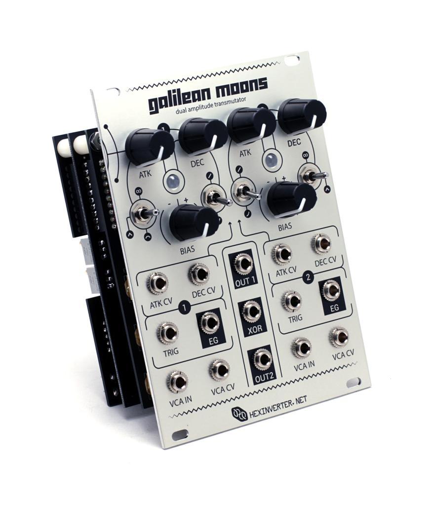
17 Install the Panel and Knobs Finally, install the panel. Test the module to make sure it s all working properly, then install the knobs as a final step! You may need to tune the LEDs before they work as expected. See the User Manual for calibration procedures. Here s what it will look like when done: 17

18 Universal Wiring Guide Step 1: Controls 18
19 Step 2: Power/Ground 19
MAIN PCB (The small one) OPEN MAIN BOARD BAG A
 OPEN MAIN BOARD BAG A") THANKS FOR CHOOSING ONE OF OUR KITS! This manual has been written taking into account the common issues that we often find people experience in our workshops. The order in which the components are placed
THANKS FOR CHOOSING ONE OF OUR KITS! This manual has been written taking into account the common issues that we often find people experience in our workshops. The order in which the components are placed
Mal-2 assembly guide v1.0
 Mal-2 assembly guide v.0 SONIC POTIONS Schematic and BOM The BOM can be found on Google Docs Prepare the PCB Separate the PCBs using some pliers. PCB We start with the lower PCB and assemble it beginning
ANTUMBRA FADE MANUAL
 ANTUMBRA FADE MANUAL TABLE OF CONTENTS 01. INSTALLATION 4 02. BACK 5 03. FRONT 6 04. USE 7 05. LINK 8 06. BILL OF MATERIALS 9 07. BUILD NOTES 10 08. BACK 11 09. FRONT 14 10. MODIFICATION 15 11. FINISHED
Main PCB (The small one)
") Thanks for choosing our kits! This manual is written taking with the problems that we usually find in our workshops in mind. Also the order is meant to make assembly as easy as possible. Some steps are
Thanks for choosing our kits! This manual is written taking with the problems that we usually find in our workshops in mind. Also the order is meant to make assembly as easy as possible. Some steps are
Tube Cricket Build Guide
 Tube Cricket Build Guide The Tube Cricket is a small-wattage amp that puts out about 1 watt of audio power. With a 12AU7 tube-preamp and a JRC386 power amp, the Tube Cricket gives you great tone in a compact
VU-1 VU Meter Kit Volume Unit Meter
 VU-1 VU Meter Kit Volume Unit Meter Simplicity Counts, Detail Matters. No part of this document may be reproduced, either mechanically or electronically, posted online on the Internet, in whole or in part,
While the parts are already inventoried at the factory, please verify the inventory check as you go:
 Thank you for purchasing the kit for building the WJ9J DTMF controller. After building, you should read the document on operation (WJ9JDTMFControllerV5.pdf) in order to use. This is also in the link in
Atari PICO Composite Mod Board Installation Instructions:
 Atari PICO Composite Mod Board Installation Instructions: Installation Guide 6 Switch Atari 2600 6 Switch Video Mod Installation Guide Disclaimer: I am not responsible for any damage done to your Atari.
Documentation VFD clock 8 a clock
 Documentation VFD clock 8 a clock This documentation is protected by our copyright. It must not be used for commercial purposes. Congratulations on your purchase of your VFD clock. To guarantee success
Introduction 1. Green status LED, controlled by output signal ST. Sounder, controlled by output signal Q6. Push switch on input D6
 Introduction 1 Welcome to the GENIE microcontroller system! The activity kit allows you to experiment with a wide variety of inputs and outputs... so why not try reading sensors, controlling lights or
Parts Checklist - Please note there is no resistor R3. Diodes, LED and transistors are polarized see construction stages
 Xtal Check Kit build Read me first! -------- UPDATED GUIDE------ September 12, 2018--------- The following steps are designed to get your Xtal check kit built and operational. This is a good beginner s
GUIDE TO ASSEMBLY OF ERICA SYNTHS DELAY MODULE
 If you are reading this, most probably, you are about to build Erica Synths DIY DELAY module. The module is 4mm deep, skiff friendly, has solid mechanical construction and doesn t require wiring. Erica
Pixie Construction Notes
 Pixie Construction Notes PCB V2a February 4 th 2015 Please note that this document is still currently under revision and we apologise for any errors or omissions. Readers should feel free to e-mail any
MAKE AN RGB CONTROL KNOB.
 MAKE AN RGB CONTROL KNOB. This is a knob based colour changing controller that uses a custom programmed microcontroller to pack a lot of features into a small affordable kit. The module can drive up to
NewScope-7A Operating Manual
 2016 SIMMCONN Labs, LLC All rights reserved NewScope-7A Operating Manual Preliminary May 13, 2017 NewScope-7A Operating Manual 1 Introduction... 3 1.1 Kit compatibility... 3 2 Initial Inspection... 3 3
DIY KIT MHZ 8-DIGIT FREQUENCY METER
 This kit is a stand-alone frequency meter capable of measuring repetitive signals up to a frequency of 50MHz. It has two frequency ranges (15 and 50 MHz) as well as two sampling rates (0.1 and 1 second).
SN-Class Nixie Clock Kits
 Assembly Instructions And User Guide SN-Class Nixie Clock Kits - 1 - REVISION HISTORY Issue Date Reason for Issue Number 1 20 November 2017 New document - 2 - 1. INTRODUCTION 1.1 About the How can the
RF Nomad Semi-SMT. SDIY Kit Assembly Manual
 RF Nomad Semi-SMT Introduction Thanks for purchasing the RF Nomad SDIY kit from Evaton Technologies! The RF Nomad SDIY kit is a voltage-controlled shortwave radio receiver in Eurorack format. The RF Nomad
Fixed Audio Output for the K2 Don Wilhelm (W3FPR) & Tom Hammond (NØSS) v August 2009
 & Tom Hammond (NØSS) v August 2009") Fixed Audio Output for the K2 Don Wilhelm (W3FPR) & Tom Hammond (NØSS) v. 2.1 06 August 2009 I have had several requests to provide a fixed audio output from the K2. After looking at the circuits that
Fixed Audio Output for the K2 Don Wilhelm (W3FPR) & Tom Hammond (NØSS) v. 2.1 06 August 2009 I have had several requests to provide a fixed audio output from the K2. After looking at the circuits that
N3ZI Digital Dial Manual For kit with Serial LCD Rev 3.04 Aug 2012
 N3ZI Digital Dial Manual For kit with Serial LCD Rev 3.04 Aug 2012 Kit properly assembled and configured for Standard Serial LCD (LCD Not yet connected) Kit Components Item Qty Designator Part Color/Marking
Assembly Instructions And User Guide. Nixie FunKlock. FunKlock Issue 4 (1 February 2017)
") Assembly Instructions And User Guide Nixie FunKlock - 1 - Issue Number Date REVISION HISTORY 4 1 February 2017 New diode for D2 3 27 December 2013 C7 / C8 error page 15 2 7 November 2013 Errors corrected
Assembly Instructions And User Guide Nixie FunKlock - 1 - Issue Number Date REVISION HISTORY 4 1 February 2017 New diode for D2 3 27 December 2013 C7 / C8 error page 15 2 7 November 2013 Errors corrected
TKEY-K16. Touch CW automatic electronic keyer. (No moving parts no contacts) Assembly manual. Last review: March 15, 2018
 Assembly manual. Last review: March 15, 2018") TKEY-K16 Touch CW automatic electronic keyer (No moving parts no contacts) Assembly manual Last review: March 15, 2018 Commands and use manual of the K16 and Updates and news: www.ea3gcy.com Thanks for
TKEY-K16 Touch CW automatic electronic keyer (No moving parts no contacts) Assembly manual Last review: March 15, 2018 Commands and use manual of the K16 and Updates and news: www.ea3gcy.com Thanks for
Nixie Clock Type Frank 2 Z570M
 Assembly Instructions And User Guide Nixie Clock Type Frank 2 Z570M Software version: 7R PCB Revision: 11 April 09-1 - 1. INTRODUCTION 1.1 About the clock Nixie clock type Frank 2 is a compact design with
Lab 7: Soldering - Traffic Light Controller ReadMeFirst
 Lab 7: Soldering - Traffic Light Controller ReadMeFirst Lab Summary The two-way traffic light controller provides you with a quick project to learn basic soldering skills. Grading for the project has been
Nixie Clock Kit IN-12B color LED backlit Operation Manual Nixie Clock Kit IN-12B V6.0 ( All Right Reserved 2015 )
") Nixie Clock Kit IN-B color LED backlit Operation Manual Nixie Clock Kit IN-B V. ( All Right Reserved ) - - Operation Manual IN-B Nixie Clock Power for your Nixie Clock The clock does not include a wall
Nixie Clock Kit IN-B color LED backlit Operation Manual Nixie Clock Kit IN-B V. ( All Right Reserved ) - - Operation Manual IN-B Nixie Clock Power for your Nixie Clock The clock does not include a wall
UAV Ultimate Atari Video A7800
 UAV Ultimate Atari Video A7800 Basic Install guide because this is really easy mod to do! The UAV is a wonderful piece of tech for what it can do. To summarize, the UAV is a replacement video encoder and
MONO AMPLIFIER KIT ESSENTIAL INFORMATION. Version 2.2 CREATE YOUR OWN SPEAKER DOCK WITH THIS
 ESSENTIAL INFORMATION BUILD INSTRUCTIONS CHECKING YOUR PCB & FAULT-FINDING MECHANICAL DETAILS HOW THE KIT WORKS CREATE YOUR OWN SPEAKER DOCK WITH THIS MONO AMPLIFIER KIT Version 2.2 Build Instructions
Total solder points: 123 Difficulty level: beginner 1. advanced AUDIO ANALYZER K8098. audio gea Give your. . high-tech ILLUSTRATED ASSEMBLY MANUAL
 Total solder points: 123 Difficulty level: beginner 1 2 3 4 5 advanced AUDIO ANALYZER K8098 ra audio gea Give your. look high-tech ILLUSTRATED ASSEMBLY MANUAL H8098IP-1 Features & Specifications Features
DL-1A. RF dummy load - 50Ω 20W. Assembly manual. Last update: May 1, Thank you for constructing the DL-1A dummy load kit
 DL-1A RF dummy load - 50Ω 20W Assembly manual Last update: May 1, 2016 ea3gcy@gmail.com Updates and news at: www.qsl.net/ea3gcy Thank you for constructing the DL-1A dummy load kit Have fun assembling it
Part (A) Controlling 7-Segment Displays with Pushbuttons. Part (B) Controlling 7-Segment Displays with the PIC
 Controlling 7-Segment Displays with Pushbuttons. Part (B) Controlling 7-Segment Displays with the PIC") Name Name ME430 Mechatronic Systems: Lab 6: Preparing for the Line Following Robot The lab team has demonstrated the following tasks: Part (A) Controlling 7-Segment Displays with Pushbuttons Part (B) Controlling
Name Name ME430 Mechatronic Systems: Lab 6: Preparing for the Line Following Robot The lab team has demonstrated the following tasks: Part (A) Controlling 7-Segment Displays with Pushbuttons Part (B) Controlling
8 PIN PIC PROGRAMMABLE BOARD (DEVELOPMENT BOARD & PROJECT BOARD)
") ESSENTIAL INFORMATION BUILD INSTRUCTIONS CHECKING YOUR PCB & FAULT-FINDING MECHANICAL DETAILS HOW THE KIT WORKS LEARN ABOUT PROGRAMMING WITH THIS 8 PIN PIC PROGRAMMABLE BOARD (DEVELOPMENT BOARD & PROJECT
ESSENTIAL INFORMATION BUILD INSTRUCTIONS CHECKING YOUR PCB & FAULT-FINDING MECHANICAL DETAILS HOW THE KIT WORKS LEARN ABOUT PROGRAMMING WITH THIS 8 PIN PIC PROGRAMMABLE BOARD (DEVELOPMENT BOARD & PROJECT
Nixie Clock Type Frank 3
 Assembly Instructions And User Guide Nixie Clock Type Frank 3 Software version: 7R PCB Version: 11 April 09-1 - 1. INTRODUCTION 1.1 About the clock Nixie clock type Frank 3 is a compact design with all
Lab 7: Soldering - Traffic Light Controller ReadMeFirst
 Lab 7: Soldering - Traffic Light Controller ReadMeFirst Lab Summary The two way traffic light controller provides you with a quick project to learn basic soldering skills. Grading for the project has been
ASM-2 Manual Appendix A
 ASM-2 Manual Appendix A Assembly Guidelines June 30 th, 2005 Please note that this document is still currently under revision and we apologise for any errors or omissions. Readers should feel free to e-mail
COLOUR CHANGING USB LAMP KIT
 TEACHING RESOURCES SCHEMES OF WORK DEVELOPING A SPECIFICATION COMPONENT FACTSHEETS HOW TO SOLDER GUIDE SEE AMAZING LIGHTING EFFECTS WITH THIS COLOUR CHANGING USB LAMP KIT Version 2.1 Index of Sheets TEACHING
TECHNOLOGY WILL SAVE US: THE LUMIPHONE
 TECHNOLOGY WILL SAVE US: THE LUMIPHONE This is a step-by-step guide to soldering your own Lumiphone. The equipment you should have at your station: goggles, soldering mat, soldering Iron, solder and side
Build Your Own Clone Super 8 Kit Instructions
 Build Your Own Clone Super 8 Kit Instructions Warranty: BYOC, Inc. guarantees that your kit will be complete and that all parts and components will arrive as described, functioning and free of defect.
PR-101 STEREO PREAMPLIFIER Phono Preamp ASSEMBLY MANUAL
 PR-101 STEREO PREAMPLIFIER Phono Preamp ASSEMBLY MANUAL 2016 AkitikA LLC All rights reserved Revision 1p18 March 12, 2016 Page 1 of 24 Table of Contents Table of Contents... 2 Table of Figures... 2 Section
DIY Guide - Building Franky v1.1, the SEGA Audio and Videocard for MSX
 DIY Guide - Building Franky v1.1, the SEGA Audio and Videocard for MSX 2015 FRS & MSXpró. Translation by FRS and Supersoniqs. Table of Contents Introduction... 3 Materials needed... 3 Audio volume boost...
N3ZI Digital Dial Manual For kit with Backlit LCD Rev 4.00 Jan 2013 PCB
 N3ZI Digital Dial Manual For kit with Backlit LCD Rev 4.00 Jan 2013 PCB Kit Components Item Qty Designator Part Color/Marking PCB 1 LCD Display 1 LCD 1602 Volt Regulator 1 U1 78L05, Black TO-92 Prescaler
Introduction 1. Green status LED, controlled by output signal ST
 Introduction 1 Welcome to the magical world of GENIE! The project board is ideal when you want to add intelligence to other design or electronics projects. Simply wire up your inputs and outputs and away
ELECTRONIC GAME KIT ESSENTIAL INFORMATION. Version 2.0 BUILD YOUR OWN MEMORY & REACTIONS
 ESSENTIAL INFORMATION BUILD INSTRUCTIONS CHECKING YOUR PCB & FAULT-FINDING MECHANICAL DETAILS HOW THE KIT WORKS BUILD YOUR OWN MEMORY & REACTIONS ELECTRONIC GAME KIT Version 2.0 Build Instructions Before
Introduction 1. Digital inputs D6 and D7. Battery connects here (red wire to +V, black wire to 0V )
") Introduction 1 Welcome to the magical world of GENIE! The project board is ideal when you want to add intelligence to other design or electronics projects. Simply wire up your inputs and outputs and away
Introduction 1 Welcome to the magical world of GENIE! The project board is ideal when you want to add intelligence to other design or electronics projects. Simply wire up your inputs and outputs and away
Christmas LED Snowflake Project
 Christmas LED Snowflake Project Version 1.1 (01/12/2008) The snowflake is a follow-on from my Christmas star project from a few years ago. This year I decided to make a display using only white LEDs, shaped
ELECTRONIC GAME KIT TEACHING RESOURCES. Version 2.0 BUILD YOUR OWN MEMORY & REACTIONS
 TEACHING RESOURCES SCHEMES OF WORK DEVELOPING A SPECIFICATION COMPONENT FACTSHEETS HOW TO SOLDER GUIDE BUILD YOUR OWN MEMORY & REACTIONS ELECTRONIC GAME KIT Version 2.0 Index of Sheets TEACHING RESOURCES
Nixie Tube Clock Type Marsden
 Assembly Instructions And User Guide Nixie Tube Clock Type Marsden Software version: RTC-1.3 PCB Revision: 16 Aug 10-1 - 1. INTRODUCTION 1.1 About the clock Nixie clock type Marsden is a compact design
Bill of Materials: Super Simple Water Level Control PART NO
 Super Simple Water Level Control PART NO. 2169109 Design a simple water controller in which electrodes are required to sense high and low water levels in a tank. Whenever the water level falls below the
FSM User Guide Page 1 of 28
 FSM User Guide Page 1 of 28 Field Strength Meter User Guide and Kit Assembly Instructions PCB V1.1 Important: Always use or print this document in colour as there are references to the colours of components.
RSL MusicPower Plug-In Installation Manual For Naim NAC 72 Preamp
 RSL MusicPower Plug-In Installation Manual For Naim NAC 72 Preamp (Updated to reflect the adjustable gain output boards Z200V) www.ryansoundlab.com RSL MusicPower Plug-In Installation Manual for Naim NAC
ADD AN AUDIO MESSAGE TO YOUR PRODUCT WITH THIS RECORD & PLAYBACK KIT
 ADD AN AUDIO MESSAGE TO YOUR PRODUCT WITH THIS RECORD & PLAYBACK KIT BUILD INSTRUCTIONS Before you start take a look at the Printed Circuit Board (PCB). The components go in the side with the writing on
Etherwave Plus Field Upgrade Instructions
 Etherwave Plus Field Upgrade Instructions The Etherwave Plus Field Upgrade is an advanced project for upgrading a standard Moog Music Etherwave theremin to the Etherwave Plus. The new features of the Etherwave
Hamcrafters K44 CW Keyboard/Reader Kit Assembly Guide Revision A.0
 Introduction Figure 1 Assembled K44 This document will describe how to assemble and test a K44 Kit. The assembly requires reasonably good soldering skill. Before you start working, gather the following
What is the E560? Connecting to the power supply
 PAGE 1 E560 Deflector Shield DIY Kit www.synthtech.com/euro/e560 What is the E560? The Synthesis Technology E560 is a combination frequency shifter, phaser and ring modulator. The audio is mono in, and
AT-AUTO (tm) QRO Keyline Upgrade Kit Installation Manual
 QRO Keyline Upgrade Kit Installation Manual") AT-AUTO (tm) QRO Keyline Upgrade Kit Installation Manual P.O. Box 341543 Beavercreek, Ohio 45434 5 September, 2015 Copyright 2015 ii Contents 1 Introduction 2 1.1 General Description and Purpose........................
AT-AUTO (tm) QRO Keyline Upgrade Kit Installation Manual P.O. Box 341543 Beavercreek, Ohio 45434 5 September, 2015 Copyright 2015 ii Contents 1 Introduction 2 1.1 General Description and Purpose........................
Building a MidiBox LCD Cable
 Building a MidiBox LCD Cable By Jim Henry, 3-Apr-2004 An LCD panel may be connected to the Core module by a 16 conductor flat ribbon cable. A 16 pin insulation displacement connector (IDC) terminates one
Analog Style LED Clock
 Analog Style LED Clock Operation and Assembly Manual For use with PCB Rev 2.1 Copyright 2018 All Rights Reserved. Manual version 2.1c, for use with PCB revision 2.1, Software version 2.0.0. The electronic
LP-PAN Preamp Kit Assembly Manual
 LP-PAN Preamp Kit Assembly Manual December 2010 TelePost Incorporated Rev. A9 1 Table of Contents Introduction... 2 Specifications... 3 Parts List... 4 Assembly... 5 Checkout / Schematic... 9 Introduction
Commissioning Guide. firepickdelta. Commissioning Guide. Written By: Neil Jansen firepickdelta.dozuki.com Page 1 of 22
 firepickdelta Commissioning Guide Written By: Neil Jansen 2017 firepickdelta.dozuki.com Page 1 of 22 Step 1 Pre-Requisites Before commissioning, please make sure ALL of the following steps have been completed,
Multi-Key v2.4 Multi-Function Amplifier Keying Interface
 Multi-Key v2.4 Multi-Function Amplifier Keying Interface ASSEMBLY & OPERATION INSTRUCTIONS INTRODUCTION The Harbach Electronics, LLC Multi-Key is a multi-function external device designed for the safe
Theremino pulsometer
 Theremino System Theremino pulsometer Optical sensor for the arrhythmia detection theremino System - Pulsometer - December 8, 2017 - Page 1 Sensors of all types On the Internet there are many ideas to
Installing The PK-AM keyer and. from Jackson Harbor Press Operating: A Morse code keyer chip with pot speed control
 Installing The PK-AM keyer and from Jackson Harbor Press Operating: A Morse code keyer chip with pot speed control The PK-AM keyer is a modification for the PK-AM kit, it changes the AM transmitter to
And there are countless others. It s probably best to study these before you continue..
 Prerequisites Soldering iron (nothing too special, any cheap-ass iron will do) Soldering tin Dupont wire (to hook up panel mount connectors) Diagonal cutters for cutting away all the legs of soldered components
DDS VFO CONSTRUCTION MANUAL. DDS VFO Construction Manual Issue 1.1 Page 1
 DDS VFO CONSTRUCTION MANUAL DDS VFO Construction Manual Issue 1.1 Page 1 Important Please read before starting assembly STATIC PRECAUTION The DDS VFO kit contains the following components which can be
ENGR 40M Project 3a: Building an LED Cube
 ENGR 40M Project 3a: Building an LED Cube Lab due before your section, October 31 November 3 1 Introduction In this lab, you ll build a cube of light-emitting diodes (LEDs). The cube is wired to an Arduino,
DEM 9ULNACK 3.4 GHz. PHEMT LNA amplifier complete kit assembly guide
 DEM 9ULNACK 3.4 GHz. PHEMT LNA amplifier complete kit assembly guide SPECIFICATIONS Noise Figure: < 0.8 db Gain: > 15 db Frequency Range: 3400-3500 MHz Input Voltage: 7-16 VDC Description: The 9ULNACK
7 SEGMENT LED DISPLAY KIT
 ESSENTIAL INFORMATION BUILD INSTRUCTIONS CHECKING YOUR PCB & FAULT-FINDING MECHANICAL DETAILS HOW THE KIT WORKS CREATE YOUR OWN SCORE BOARD WITH THIS 7 SEGMENT LED DISPLAY KIT Version 2.0 Which pages of
QUIZ BUZZER KIT TEACHING RESOURCES. Version 2.0 WHO ANSWERED FIRST? FIND OUT WITH THIS
 TEACHING RESOURCES SCHEMES OF WORK DEVELOPING A SPECIFICATION COMPONENT FACTSHEETS HOW TO SOLDER GUIDE WHO ANSWERED FIRST? FIND OUT WITH THIS QUIZ BUZZER KIT Version 2.0 Index of Sheets TEACHING RESOURCES
Assembly and Operating Instructions for HiViz.com Kits
 information and inspiration for students, teachers and hobbyists About Tools Products Activities Galleries Projects FAQ Links Contact Assembly and Operating Instructions for HiViz.com Kits For best results
Nixie Clock Type Quattro'
 Assembly Instructions And User Guide Nixie Clock Type Quattro' - 1 - Issue Number Date REVISION HISTORY 2 8 Sept 2012 Errors corrected 1 27 July 2012 New document Reason for Issue - 2 - 1.1 Nixie Quattro
Audio Interface II Manual. Audio Interface II. Eurorack <-> Line Level Audio Interface. Manual Revision: 1.0
 Audio Interface II Eurorack Line Level Audio Interface Manual Revision: 1.0 Overview The Audio Interface II allows you to interface your Eurorack modular system to the pro balanced line level world
"shell" digital storage oscilloscope (Beta)
") "shell" digital storage oscilloscope (Beta) 1. Main board: solder the element as the picture shows: 2. 1) Check the main board is normal or not Supply 9V power supply through the connector J7 (Note: The
"shell" digital storage oscilloscope (Beta) 1. Main board: solder the element as the picture shows: 2. 1) Check the main board is normal or not Supply 9V power supply through the connector J7 (Note: The
XTAL Bank DDS Version 0.02 Sept Preliminary, highly likely to contain numerous errors
 XTAL Bank DDS Version 002 Sept 7 2012 Preliminary, highly likely to contain numerous errors The photo above shows the fully assembled Xtal Bank DDS with 2 DDS modules installed (The kit is normally only
Industrial Monitor Update Kit
 Industrial Monitor Update Kit (Bulletin Number 6157) Installation Instructions 2 Table of Contents Table of Contents Industrial Monitor Update Kit... 3 Overview... 3 Part 1 - Initial Preparation... 5 Part
Color Organ Triple Deluxe II.
 http://wwwinstructablescom/id/color-organ-triple-deluxe-ii/ Food Living Outside Play Technology Workshop Color Organ Triple Deluxe II by ledartist on January 13, 2013 Table of Contents Color Organ Triple
TR-Plus T/R Switch Assembly and Operation Manual. Introduction
 TR-Plus T/R Switch Assembly and Operation Manual Revised: 7 February 2015 2015 Tucson Amateur Packet Radio Corporation Introduction The TAPR TR-Plus is a transmit/receive ( T/R ) switch that connects a
MACH3 LaserAce Installation Manual Revision 1. MACH3 LaserAce Installation Manual
 WWW.LASERARCADE.COM MACH3 LaserAce Installation Manual Revision 1 MACH3 LaserAce Installation Manual Table of Contents Introduction...1 Parts supplied with MACH3 FNI...1 Why the MACH3 FNI is required...2
Build A Video Switcher
 Build A Video Switcher VIDEOSISTEMAS serviciotecnico@videosistemas.com www.videosistemas.com Reprinted with permission from Electronics Now Magazine September 1997 issue Copyright Gernsback Publications,
How To Build Megavolt s Small Buffered JTAG v1.2
 How To Build Megavolt s Small Buffered JTAG v1.2 Abstract A JTAG cable should be considered mandatory equipment for any serious tester. It provides a means to backup the information in the receiver and
MOD028 GLOCKENSPIEL TECHNO-MUSIC-OLOGY
 MOD028 GLOCKENSPIEL TECHNO-MUSIC-OLOGY MOD028 - Techno-music-ology Kit Contents Motor Controller PCBs 14 220R (red red brown gold) resistors 2 330R (orange orange brown gold) resistors 16 1N4001 diodes
Audio Interface II Manual. Audio Interface II. Eurorack <-> Line Level Audio Interface. Manual Revision:
 Audio Interface II Eurorack Line Level Audio Interface Manual Revision: 2018.09.13 Table of Contents Table of Contents Compliance Installation Installing Your Module Overview Features Front Panel Controls
INteractive LED Panel Kits
 INteractive LED Panel Kits A DIY Electronics Project designed by Evil Mad Scientist Laboratories Making the World a Better Place,One Evil Mad Scientist at a Time Support: http://www.evilmadscientist.com/forum/
Phoenix digital Board, formally known as Shruthi is 100% compatible, in fact it is the same board, same dimensions but with another name.
 Phoenix digital Board, formally known as Shruthi is 00% compatible, in fact it is the same board, same dimensions but with another name. Phoenix control board assembly instructions Schematics and PCB The
COMPONENT PREPARATION AND MANUAL INSERTION TRAINING CERTIFICATION TEST (DVD-44C) v.2
 v.2") This test consists of fifteen multiple-choice questions. All questions are from the video: Component Preparation and Manual Insertion (DVD-44C). Each question has only one most correct answer. Circle the
This test consists of fifteen multiple-choice questions. All questions are from the video: Component Preparation and Manual Insertion (DVD-44C). Each question has only one most correct answer. Circle the
Bas Gialopsos Atari PureVideo Encoder Module 2600VECr5.2
 Bas Gialopsos 2014 Atari PureVideo Encoder Module 2600VECr5.2 Table of Contents Description Disclaimer Technical and Signal Identification Installation Instructions Tools Required Caution Installation
Nixie Clock Type IN-8 & NL840 Nixie'
 Assembly Instructions And User Guide Nixie Clock Type IN-8 & NL840 Nixie' - 1 - REVISION HISTORY Issue Number Date 4 15 December 2016 New diode for D2 3 30 August 2014 Typos 2 25 June 2014 Added NL840
Ten-Tec (865) Service Department:(865)
 Service Department:(865)") Ten-Tec (865) 453-7172 Service Department:(865) 428-0364 Installation Instructions for Ten-Tec Jupiter AT538K Tuner Kit The installation of the AT538K is divided into two steps. The first step is to reprogram
Ten-Tec (865) 453-7172 Service Department:(865) 428-0364 Installation Instructions for Ten-Tec Jupiter AT538K Tuner Kit The installation of the AT538K is divided into two steps. The first step is to reprogram
RECORD & PLAYBACK KIT
 TEACHING RESOURCES SCHEMES OF WORK DEVELOPING A SPECIFICATION COMPONENT FACTSHEETS HOW TO SOLDER GUIDE ADD AN AUDIO MESSAGE TO YOUR PRODUCT WITH THIS RECORD & PLAYBACK KIT Version 2.1 Index of Sheets TEACHING
These are the illustrated step-by-step guidelines for upgrading your Quad 34 with the Dada Electronics upgrade-kit.
 Quad 34 DIY illustrated guidelines version 2.12 These are the illustrated step-by-step guidelines for upgrading your Quad 34 with the Dada Electronics upgrade-kit. The Quad 34 is a very good preamplifier,
Nixie Clock Type Frank 3'
 Assembly Instructions And User Guide Nixie Clock Type Frank 3' - 1 - REVISION HISTORY Issue Number Date Reason for Issue 4 16 December 2016 New diode for D2 3 12 November 2012 Improved first clock test
Mini-Yack Iambic Keyer
 Mini-Yack Iambic Keyer Assembly Instructions Mini-Yack is a "bare bones" Iambic keyer for embedding into QRP and home brew equipment. The keyer has the following features: Keying from 1-50WPM YACK memory
STROBOSCOPE LIGHT EFFECT KIT
 STROBOSCOPE LIGHT EFFECT KIT Easy to build stroboscope for general applications Flash frequency: 5 to 15 flashes per second Power supply: 110VAC Power consumption: 13W max. PCB dimensions: 50 x 75mm modifications
2000 Series Weather Stations Analog Temperature / RH Sensor Upgrade Kit PRODUCT MANUAL KIT # 3613WDU
 2000 Series Weather Stations Analog Temperature / RH Sensor Upgrade Kit PRODUCT MANUAL KIT # 3613WDU 1 The 3613WDU Analog Temperature / RH Sensor Upgrade Kit is used to upgrade Watchdog 2000 Series Weather
Shifty Manual v1.00. Shifty. Voice Allocator / Hocketing Controller / Analog Shift Register
 Shifty Manual v1.00 Shifty Voice Allocator / Hocketing Controller / Analog Shift Register Table of Contents Table of Contents Overview Features Installation Before Your Start Installing Your Module Front
Prototyping & Engineering Electronics Kits Magic Mandala Kit Guide
 Prototyping & Engineering Electronics Kits Magic Mandala Kit Guide odysseyboard.com Please refer to www.odysseyboard.com for a PDF updated version of this guide. Magic Mandala Guide version 1.0, February,
Constructing My VK5JST Aerial (Antenna) Analyser Kit July 2009 (ver. 22) By Andrew Cornwall / VE1COR
 Analyser Kit July 2009 (ver. 22) By Andrew Cornwall / VE1COR") Constructing My VK5JST Aerial (Antenna) Analyser Kit July 2009 (ver. 22) By Andrew Cornwall / VE1COR HAPPY ENDING FOR MY MISPLACED ANTENNA ANALYZER My wife and I are Snowbirds, which means we head south
Constructing My VK5JST Aerial (Antenna) Analyser Kit July 2009 (ver. 22) By Andrew Cornwall / VE1COR HAPPY ENDING FOR MY MISPLACED ANTENNA ANALYZER My wife and I are Snowbirds, which means we head south
A BBD replacement and adjustment procedure
 A-188-1 BBD replacement and adjustment procedure The following steps have to be carried out with the unpowered A-188-1 module (i.e. the module is not connected to the A-100 bus board or the module is connected
The video-signals on 128K ZX Spectrum models
 The video-signals on 128K ZX Spectrum models This document describes some fairly easy video-enhancements that should result in perfectly clear and crisp pictures from your ZX Spectrum! (Document version:
imac Intel 20" EMC 2133 and 2210 LCD Backlights (CCFL) Replacement
 Replacement") imac Intel 20" EMC 2133 and 2210 LCD Backlights (CCFL) Replacement The CCFL back lights are replaceable. I have pulled mine apart and documented my method. '''NOTE''' This is not for the feint hearted!
imac Intel 20" EMC 2133 and 2210 LCD Backlights (CCFL) Replacement The CCFL back lights are replaceable. I have pulled mine apart and documented my method. '''NOTE''' This is not for the feint hearted!
Dual Comparator and Gate Delay CV and Audio Processor
 Oakley - Modular Dual Comparator and Gate Delay CV and Audio Processor PCB Issue 1 User s Guide V1.2 Tony Allgood B.Eng PGCE Oakley Sound Systems PENRITH CA10 1HR United Kingdom Introduction This is an
nonlinearcircuits cellf action build guide & BOM VERS. 1
 nonlinearcircuits cellf action build guide & BOM VERS. 1 Please read thru before soldering anything, there are some component values that need to be changed or decided upon before starting. If you spot