DRAFT RELEASE FOR BETA EVALUATION ONLY
|
|
|
- Kelly Hensley
- 5 years ago
- Views:
Transcription

1 IPM-16 In-Picture Audio Metering User Manual DRAFT RELEASE FOR BETA EVALUATION ONLY Ver 0.2 April
2 Contents Introduction...3 In Picture Audio Meter Displays...4 Installation...7 External Audio Board Switches External Audio Input Connector Pins Configuration...9 General Settings Main Page...9 Video Resolution Control Page...11 Level Meters General Page...12 Size and Position Page...14 Transition Points Page...15 EBU Loudness General Page...16 Size and Position Page...18 Transition Points...19 Audio Channel Names Page Audio Phase Correlation Meters Page System Alarms Alarm Status Page...22 Audio Loss Page...24 Audio Over Page...26 Phase Correlation...27 Audio Carrier Loss Page...28 Video Page...29 Audio In / Out Page Update Firmware...32 Specifications
3 Introduction The IPM-16 is an audio monitoring solution with video-in-picture audio metering and alarms. This flexible solution supports the metering of SDI embedded audio, external AES or analogue audio, or a mixture of these. Up to 4 groups of meters may be displayed simultaneously, allowing up to 16 channels to be metered. Another two EBU R128 compliant loudness meters may be displayed, with each one allowing up to 5 channels to contribute to the loudness levels. It provides an effective alarm system for both audio and video errors. Two channels of analogue audio monitor outputs may be derived from any input, as well as up to 8 audio channels on the HDMI output. The IPM-16 is configured by attaching it to a PC via USB. The control program used for doing this can also be used for monitoring alarms. Up to 16 sets of configurations can be stored on the IPM-16 and quickly selected by a switch on the box. The features of the IPM-16 are: Auto SD/HD/3G SDI video input. SD/HD/3G SDI output (same format as input, no standards conversion). HDMI video and audio output Each group of audio channels metered consists of 4 channels. Up to 4 groups (total of 16 channels) of SDI embedded audio may be displayed. With the external audio card present, up to 8 AES audio pairs or 16 analogue channels can be metered. The metering can be any mixture of the embedded audio, AES audio or analogue audio inputs. Assignable meters DIN PPM, BBC PPM, Nordic PPM, VU, Extended VU, ARD+9, AES/EBU. Each group can be assigned a different meter type. Two additional EBU Mode Loudness meters are available. 4 assignable phase correlation bars. Each bar can be assigned to a pair of matching channels. Video alarms: video sync loss, black (loss of luminance), freeze frame. Audio alarms: embedded audio/aes audio carrier loss, audio loss (low-level), audio over level, out of phase. All alarms can be turned on/off for individual channels (or pairs where applicable). Fully configurable with a PC. 2 channels of analogue audio monitoring outputs. Powered by a separate 12VDC 2.5A adaptor. 3

4 In Picture Audio Meter Displays The image above shows a typical display with two peak meter groups showing 4 audio levels, and an EBU R128 loudness meter with numeric readings. Two phase correlation bars are turned on at the top of the image. 4

5 Level meters available 5

6 EBU R128 Loudness meters available 6
7 Installation Connect the 12VDC adaptor to the box and power it up. Provide an SDI video input to the input BNC. Connect a coaxial cable from either the SDI output BNC to an SDI monitor, or an HDMI cable to a monitor (or both). The image on the input should now appear on the monitor, possibly with some audio meters if the IPM-16 has previously been configured to display them. Note that is can take about 10 seconds from power up until the IPM-16 provides a valid SDI or HDMI output. External Audio Board Switches If the unit contains and EXT (external audio board) then there are some miniature DIP switches that need to be configured to ensure the audio signal is correctly terminated, depending on the type of audio to be fed in. These are switches 1 to 4. In the table below, the -n notation refers to the numbering on the DIP switch itself e.g. SW3-2 means the switch labelled 2 on SW3. Input 1 & 2 Input 3 & 4 Input 5 & 6 Input 7 & 8 Input 9 & 10 Input 11 & 12 Input 13 & 14 Input 15 & 16 Analogue In SW1-3 Off, SW1-4 Off SW1-1 Off, SW1-2 Off SW2-3 Off, SW2-4 Off SW2-1 Off, SW2-2 Off SW3-3 Off, SW3-4 Off SW3-1 Off, SW3-2 Off SW4-3 Off, SW4-4 Off SW4-1 Off, SW4-2 Off Balanced Digital In SW1-3 Off, SW1-4 On SW1-1 Off, SW1-2 On SW2-3 Off, SW2-4 On SW2-1 Off, SW2-2 On SW3-3 Off, SW3-4 On SW3-1 Off, SW3-2 On SW4-3 Off, SW4-4 On SW4-1 Off, SW4-2 On Unbalanced Digital In SW1-3 On, SW1-4 On SW1-1 On, SW1-2 On SW2-3 On, SW2-4 On SW2-1 On, SW2-2 On SW3-3 On, SW3-4 On SW3-1 On, SW3-2 On SW4-3 On, SW4-4 On SW4-1 On, SW4-2 On 7
8 External Audio Input Connector Pins The external audio comes in on a 37-pin D female connector. The pinout for both analogue and AES/EBU digital is listed below. Pin Analogue Signal Digital Signal GND 1, 10, 19, 24, 33 8

9 Configuration 16 sets of configurations are stored on the IPM-16 and selected by the hex switch on the box. To access the settings of these configurations and alter them, the MCOIPM utility needs to be installed on a PC. The IPM-16 then needs to be attached to the PC using a USB-A male to USB-Micro-B male cable (supplied). Once the IPM-16 is connected and powered up the MCOIPM utility should automatically detect it, display the General Main tab, as depicted below. As settings are changed within this utility, they immediately get updated and saved to the current configuration selected by the switch on the IPM-16. If a new configuration is selected by changing the position of the switch while running the MCOIPM utility then a warning message will appear, indicating that the new settings are being loaded. Shortly afterwards, the new settings will appear in the utility. General Settings Main Page 9
10 Settings Management User Settings 16 sets of User Settings are available. These correspond to the 16position switch on the box. The current position of this switch is displayed in this field. Whenever a change is made to any of the settings they get saved to the one currently selected by the switch immediately. Settings Name The name that has been assigned to the current setting is displayed here, and can also be edited. Restore Defaults This restores the default values to all fields in the current User Settings being used. Display Settings Use the same settings for all User Settings If this is ticked then all the settings in this Display Settings group will remain unchanged when a different set of User Settings is selected. The Display Settings fields can still be modified. If not ticked then then each set of User Settings has its own set of Display Settings. 10
11 Display Settings OSD Fade Level This sets the transparency of the metering display over the background video. 0 is completely off, 100 is fully keyed in. Display OSD on Blank Ticking this will force the background video to never be shown the Background meters will be displayed on a uniform blank background. Blank Background Colour This sets the background colour for the display when the video input signal is lost or when the blank background is forced on. Output on Video Loss This sets the video output standard to be generated when there is no video input present. (Note: If Display OSD on Blank Background is ticked and there is still video present on the input then the output format will be the same as the video input format). Scale font size based on The standard font sizes used are optimised for HD video resolution. video resolution If this box is not ticked then the fonts remain the same size in pixel units regardless of the video resolution. Therefore, when the video is SD they will be much larger proportionally to the rest of the graphics in comparison with HD. If this box is ticked then the fonts get scaled down for SD video, and they become approximately the same size proportionally to the meters as they appear in HD. The advantage of ticking this box is that the meter size to screen size ratio remains almost constant regardless of the input video format. The disadvantage is that the font is small for SD and may not be readable on some monitors. Audio Reference Levels Analogue 0dB reference This sets the analogue audio reference level. For example, if set to +4dBu then a +4dBu input signal will read 0dB on the meters. Digital reference level This sets the digital audio reference level. For example, if set to -18dBfs then a -18dBfs input signal will read 0dB on the relative meters. 11

12 Video Resolution Control Page This allows a set of User Settings to be automatically loaded when the video input resolution changes. When the Load new settings when resolution changes field is ticked, the settings that are currently loaded will always be dependent on the video input resolution and the settings assigned to this resolution. The switch on the box has no affect. 12

13 Level Meters General Page Audio Level Meters General On Each meter can be individually turned on or off. Channel x On Turns individual channels within a meter on or off using this control. Audio Source Selects the SDI embedded audio group or a group of 4 external audio channels to display in the associated meter. Scale Type Selects the type of scale to use with the associated meter. Display Type Each meter can display either normal audio level metering or sum and difference levels. Scale Position Selects the position to display the scale units labelling left, right, both sides or off. 13
14 Audio Level Meters General Scale Colour Selects the colour of the scale units labelling. Background Colour Sets the background colour of the meter. Peak Hold Time If this is set to off then no peak hold indicators are displayed. Otherwise this sets the time that the indicators maintain their peak hold levels. Peak Hold Reading The peak hold indicators can either display quasi peak or true peak levels. Quasi peak is the peak level reached when restrained by the integration time of the meter in use. True peak is the peak level of the oversampled audio without any integration applied. The audio is up-sampled to 192kHz to determine the true peak level. Peak Hold Colour Sets the colour of the peak hold indicators on each meter. Labels Labels can either be numeric or text. When numeric the channel number is displayed below each meter e.g. the number 5 will be displayed below a meter showing SDI embedded input group 2 channel 1. When set to text the channel names setup elsewhere for each input channel will be displayed below each channel on the meter. Mini Phase Bars This turns the mini phase correlation bars on or off. These get displayed above each pair of matching channels on the meter. Alarm Indicators This turns the alarm indicators on or off. These get displayed above each channel on the meter, indicating audio loss, audio over, out of phase, or carrier loss. While no alarms are present they remain dormant. When an alarm is activated the indicator will start flashing. 14

15 Size and Position Page Audio Level Meters Size and Position Horizontal Position, Vertical Position Each meter can be moved to any position on the screen. Height Each meter can be adjusted from 10% to 100% of the screen height. Bar Width Sets the width of all bar-graphs in a meter. Bar Spacing Sets the gap between the bar-graphs in a meter. 15

16 Transition Points Page Audio Level Meters Transition Points Upper-over transition, Each meter has 3 regions that can be set to different colours the lower Lower-upper transition region, upper region, and over region. This sets the transition levels dividing these regions. The levels are in relative db values, so for example if the lower-upper transition is set to -20dB and the AES absolute scale of dbfs is used then the lower-upper transition point will occur 20 db below the digital reference level (e.g. -38dBfs if the digital reference is -18dBfs). Bar Colours: Lower, Upper, Over Each region on each bar-graph in each meter can be set to its own colour. 16

17 EBU Loudness General Page EBU Loudness General On Enables the display of each loudness meter. L, R, C, Ls, Rs Source Select the source for each channel in the loudness meter. Not all 5 channels have to be present, however the assignment of a source to a particular channel in the loudness meter is significant because of the different weighting applied to Ls and Rs. Bar-graph Reading The single meter shown in the loudness display can be any of the three types of loudness measurements momentary, short term or integrated. Loudness Scale Sets the scale type. Available scales are EBU +9 relative, EBU +18 relative, EBU +9 absolute, or EBU +18 absolute. 17
18 EBU Loudness General Loudness Target This sets the loudness target in LUFS. This is only significant when a relative scale is being used, in which case the 0LU point on the scale is the loudness target (normalised audio reference level). For EBU mode this should be set to -23 LUFS. Numeric Reading: Momentary Loudness Short-term Loudness Integrated Loudness Integrated Duration Loudness Range Select any combination of these to display the desired numeric loudness measurements to the right of the loudness bar-graph. The integrated duration displays the time passed (hh:mm:ss) since the integrated loudness has started its measurement. Reset Resets the Integrated Loudness and Loudness Range measurements. The capturing of data for calculating these measurements starts again, as does the duration indicator. 18

19 Size and Position Page EBU Loudness Size and Position Horizontal Position, Vertical Position Each meter can be moved to any position on the screen. Height Each meter can be adjusted from 10% to 100% of the screen height. Bar Width Sets the width of all bar-graphs in a meter. 19

20 Transition Points EBU Loudness Transition Points Over-range threshold, Under-range threshold The loudness meter bar-graph has three regions that can be set to different colours. These two settings determine the levels of the boundaries between the regions. The levels are relative to 0LU on a relative scale or the target loudness level on an absolute scale. Under-range colour, Normal-range colour, Over-range colour Sets the three colours for the three regions. 20

21 Audio Channel Names Page - Each channel can be given a name up to 8 characters long. This is the text that will be used beneath a bar-graph in an audio meter if the channel labelling is set to text. 21
22 Audio Phase Correlation Meters Page - Phase Correlation On Turns each phase bar on or off. Audio Source Selects the two channels that are shown in the phase correlation bar. Horizontal Position, Vertical Position Sets the position of the phase bar. It can be positioned anywhere on screen. Width Sets the horizontal size of the complete phase bar. It can range from 10% of the screen width to 100%. 22

23 System Alarms Alarm Status Page Alarm Status Alarm Auto Reset Timeout This sets the auto reset timeout for all alarms. If an alarm is triggered and then its condition disappears then the alarm will automatically reset when this timeout period expires. If this is set to Off then the alarm can only be reset manually. Reset All Alarms This immediately clears any alarms that have triggered. If the condition of an alarm is still present then it will trigger again when the trigger timeout expires. 23
24 Alarm Status Audio Loss, Audio Over, Phase Correlation, Carrier Loss This shows the current status of each audio alarm type. If no alarm condition exists for each type then a green indicator appears next to the label and the status reports OK. If an alarm condition occurs on an audio channel that has its alarm enabled then the indicator goes red and the channel will be listed in the status field. Video Loss If there has been no video signal present for the timeout interval set in the Video tab, and the Video Loss alarm is enabled then this will have a red indicator and report the condition. Video Black If the luminance level of the complete picture remains below approximately 7% of white for the timeout interval set in the Video Alarm tab, and the Video Black alarm is enabled then this will have a red indicator and report the condition. Freeze Frame If the video remains digitally frozen for the timeout interval set in the Video Alarm tab, and the Freeze Frame alarm is enabled then this will have a red indicator and report the condition. Digitally frozen means no change whatsoever from frame to frame. Reset Buttons Each alarm type can be individually reset with its assigned reset button. 24
25 Audio Loss Page Audio Loss All Channels: Threshold Sets the audio loss threshold. This is relative to the audio reference level and is therefore dependent on whether the source is analogue or digital. For an analogue source it is relative to the analogue reference level e.g. if the threshold is -30dB and the audio reference level is +4dBu then the input level needs to remain continuously below -26dBu for the timeout interval before the alarm will trigger. For a digital source it is relative to the digital reference level e.g. if the threshold is -30dB and the audio reference level is -18dBfs then the input level needs to remain continuously below -48dBfs for the timeout interval before the alarm will trigger. All Channels: Enabled Switches on/off the detection of audio loss for all channels 25
26 Audio Loss All Channels: Timeout The duration that the audio loss condition must continuously persist for before the alarm will trigger. All Channels: Show Error Shows an error message on screen if an alarm exists Channel 1..16: Enable Enables/disables audio loss detection for individual channels. 26
27 Audio Over Page The controls here are the same as the audio loss ones. Refer to the description of the audio loss controls above. 27

28 Phase Correlation Phase Correlation Alarm Settings Threshold This sets the threshold for the phase correlation alarm. It can range from 0 to means that the left and right channels have very little to no correlation with each other, or if they are the same waveform then there is a 90 degree shift between them. -1 means that the left and right channels have the same signal on them but they are out of phase (one of the channels is inverted). The rest of the phase correlation controls are the same as the audio loss ones, except they are grouped by pairs of channels, not individual channels. Refer to the description of the audio loss controls above. 28
29 Audio Carrier Loss Page Carrier loss alarms relate to digital audio only (SDI embedded audio or external AES audio). It relates to the loss of the signal carrying the audio as opposed to audio silence where there is a carrier present. The carrier loss controls are the same as the audio loss ones, except they are grouped by pairs of channels, not individual channels. Refer to the description of the audio loss controls above. 29

30 Video Page Phase Correlation Alarm Settings Enable Enables/disables the detection of the associated video alarm. Timeout Sets the amount of time that the video condition must persist before the alarm is triggered. Show Error Shows an error message on screen if the associated alarm exists. 30

31 Audio In / Out Page - External Audio Input Setup Input Pair n If an external audio board is included in the system then the selection of analogue or digital inputs is configured here. The input type for each pair can be Auto, Analogue or AES/EBU. In Auto mode it detects whether the source is AES/EBU audio and if so decodes this, otherwise assumes that the source is analogue. The Detected Type field will display the current input type when Auto mode is selected, otherwise it will say Not Applicable. If there is no external audio card present then the Input Type fields will be blank and the Detected Type fields will display Card not present. In addition to selecting the external audio input type here, there are some miniature DIP switches on the external audio board that need to be set according to the audio input type. Refer to the Installation section regarding these. 31
32 Audio Output Setup Stereo Output Source This selects the audio input pair source to route to the stereo output. HDMI Audio Output This selects the 4 pairs of audio input to route to the HDMI audio outputs. 32

33 Video Measurements Video Measurements 33


34 Update Firmware From time to time, new features may become available and a firmware update will be required to take advantage of these features. To update the firmware, the latest ipm16.hex file is required. This needs to be uploaded to the IPM-16 by the MCOIPM USB utility by pressing the Update Firmware button that is located on the About tab. This will then open a Open new firmware hex file dialogue, and from here the location of the ipm16.hex on the PC must be selected. Once it is selected and the Open button is pressed the updating of firmware shall proceed. It takes about 5 minutes for firmware to be updated, and a progress bar will be displayed in the MCOIPM utility to indicate the status. The LED on the IPM-16 will also flash green while an update is occurring. Once the firmware has been updated, the version can be checked in the About tab of the MCOIPM utility. There are 2 modules that get updated the software and the hardware (FPGA). If only one of these was successful in updating then a mismatch will be reported in the About pane the FPGA Revision will report that it still needs updating. The update should be attempted again, should this occur. 34
35 Specifications Video In SDI-SDI (SMPTE259M 525/59.94, 625/50) HD-SDI (SMPTE274M, SMPTE292M, SMPTE424M Level A 720p60, 720p59.94, 720p50, 720p30, 720p29.97, 720p25, 720p24, 720p23.97, 1080i60, 1080i59.94, 1080i50, 1080p50, 1080p29.97, 1080p25, 1080p24, 1080p23.97, 1080p60, 1080p50) Video Out SDI (SMPTE259M, SMPTE274M, SMPTE424M all standards as stated above in the Video In Specifications). HDMI 1.4 CEA861D versions of the SMPTE input standards (480i60, 576i50,720p60/59.94/50, 1080i60/59.94/50, 1080p60/59.94/50) Audio In Embedded audio on SDI in Optional 16 channels of AES/EBU (32kHz to 192kHz sample rate), or 16 analogue channels, or combination of the two. Maximum analogue input input level: +24dBu peak Analogue reference level: -12dBu to +12dBu adjustable Digital reference level: -30dBfs to -6dBfs adjustable Audio Out 1 stereo pair of analogue out, selected from any audio input source 8 stereo pairs of HDMI embedded out, selected from any audio input sources Audio Processing True peak meter processing: audio up-sampled to 192kHz for peak level Loudness metering: ITU-R BS multichannel loudness algorithm Audio Meters / Ballistics Up to 4 groups of level meters, each containing up to 4 channels Up to 2 loudness meters, each one assigned up to 5 input channels (L, R, C, Ls, Rs with appropriate weightings according to ITU-R BS ) Peak hold: Select from either true-peak or quasi-peak AES/EBU (IEC ): Dynamic Range: 60dB (0 to -60dBfs) Attack Time: <5ms Decay Time: 1.5s per 20dB DIN PPM (IEC Type I): Dynamic Range: 55dB (+5 to -50dB) Attack Time: 10ms 35
36 Decay Time: 1.7s per 20dB BBC PPM (IEC Type IIa): Dynamic Range: 24dB + 3dB down from Mark 1 (+12 to -12dB) Attack Time: 10ms Decay Time: 2.8s per 20dB Nordic (IEC Type I): Dynamic Range: 54dB (+12 to -42dB) Attack Time: 10ms Decay Time: 1.7s per 20dB VU (IEC ): Dynamic Range: 23dB (+3 to -20dB) Attack Time: 300ms Decay Time: 300ms per 20dB VU EXTENDED: Dynamic Range: 60dB (+10 to -50dB) Attack Time: 300ms Decay Time: 300ms per 20dB ARD 9 (IEC Type I): Dynamic Range: 59dB (+9 to -50dB) Attack Time: 10ms Decay Time: 1.7s per 20dB Loudness (EBU R128, ITU-R BS ): Scales: EBU +9 Relative, EBU +18 Relative, EBU +9 Absolute, EBU +18 Absolute Meter Readings: Momentary, Short-term, Integrated Loudness Numeric Readings: Momentary, Short-term, Integrated Loudness, Integrated Duration, Loudness Range. Phase Correlation Up to 4 phase correlation meters Attack / decay time: 0.4s (centre to +/-1 deviation) Minimum input level: -45dBu / -60dBfs Power 12V, 2A adaptor Environmental Temperature 0 C to 30 C, Humidity 70% maximum 36
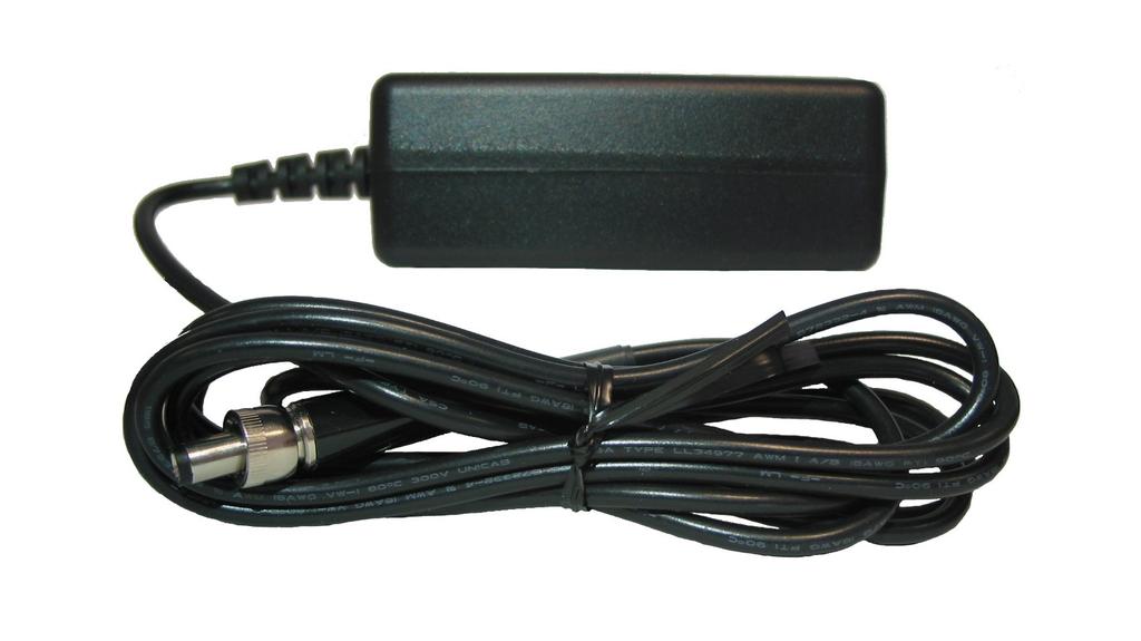
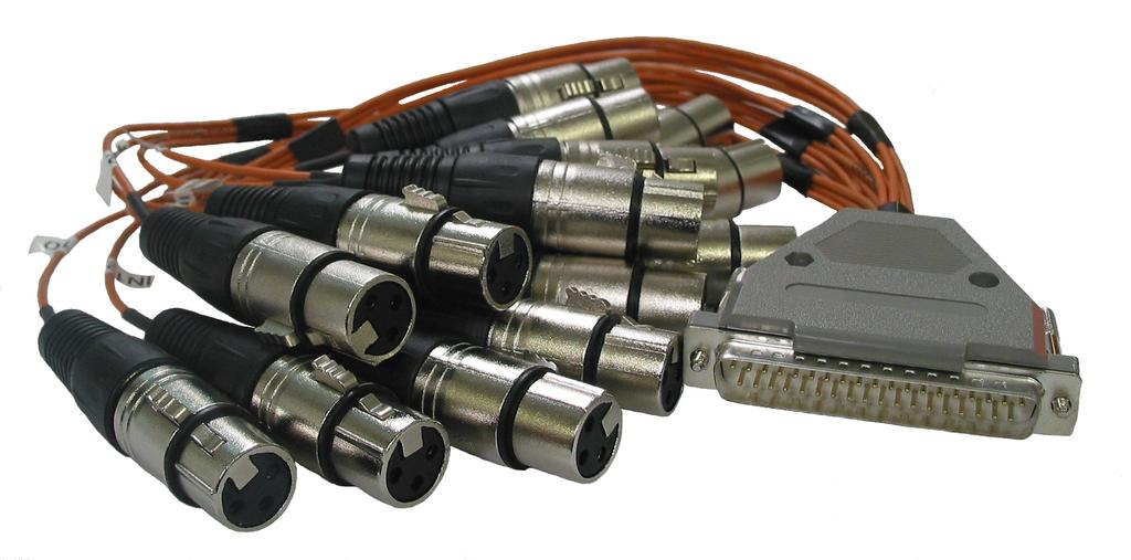
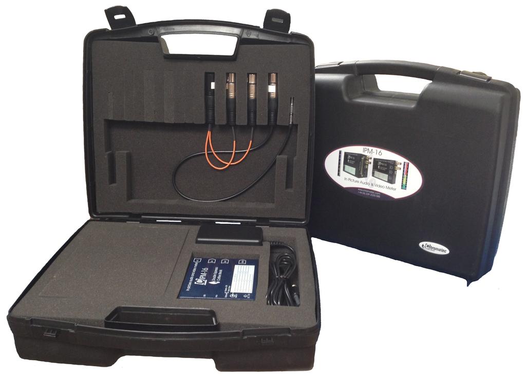
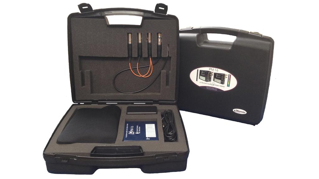
37 Contents This should just be a list of the order codes of the items that can be ordered and should match the website. Order Code Contents IPM-16 Pack 1 1 x IPM-16 1 x PSU-12V-15W-LOCK 16 channel in-picture audio and video meter. IPM-16 Pack 2 1 x IPM-16 Full accessories required for use with 1 x PSU-12V-15W-LOCK the IPM-16, excluding foam filled carry 1 x IPM-16-AUD-BRK-CAB case. 1 x IPM-16-ADAPTOR-CAB IPM-16 Pack 3 1 x IPM-16 Full accessories required for use with 1 x PSU-12V-15W-LOCK the IPM-16, including foam filled carry 1 x IPM-16-CASE case. 1 x IPM-16-AUD-BRK-CAB 1 x IPM-16-ADAPTOR-CAB IPM-16-EXT Pack 1 1 x IPM-16-EXT 1 x PSU-12V-15W-LOCK IPM-16-EXT Pack 2 1 x IPM-16-EXT Full accessories required for use with 1 x PSU-12V-15W-LOCK the IPM-16-EXT, excluding foam filled 1 x IPM-16-EXT-DXLR carry case. 1 x IPM-16-AUD-BRK-CAB 1 x IPM-16-ADAPTOR-CAB IPM-16-EXT Pack 3 1 x IPM-16-EXT Full accessories required for use with 1 x PSU-12V-15W-LOCK the IPM-16-EXT, including foam filled 1 x IPM-16-EXT-CASE carry case. 1 x IPM-16-EXT-DXLR 1 x IPM-16-AUD-BRK-CAB 1 x IPM-16-ADAPTOR-CAB PSU-12V-15W-LOCK 1 x PSU-12V-15W-LOCK Power supply for both units. IPM-16-CASE 1 x IPM-16-CASE Hard plastic, foam filled carry case for the IPM-16. IPM-16-EXT-CASE 1 x IPM-16-EXT-CASE Hard plastic, foam filled carry case for the IPM-16-EXT. As IPM-16 with additional AES and analogue input. IPM-16-AUD-BRK-CAB 1 x IPM-16-AUD-BRK-CAB Audio breakout cable to 2 x 3 way XLR plugs. IPM-16-ADAPTOR-CAB 1 x IPM-16-ADAPTOR-CAB 6 way mini XLR plug to 6 way XLR socket. IPM-16-EXT-DXLR 1 x IPM-16-EXT-DXLR 16 channel analogue or 8 channel AES input cable assembly. 37


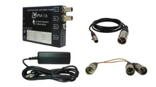
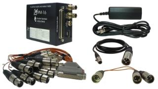
38 IPM-16 IPM-16-EXT IPM-16 Pack 2 IPM-16-EXT Pack 2 IPM-16 Pack 3 IPM-16-EXT Pack 3 PSU-12V-15W-LOCK IPM-16-EXT-DXLR 38
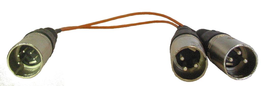
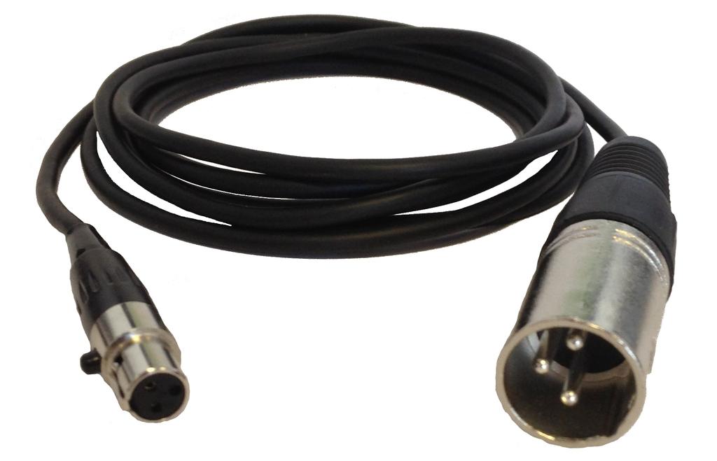
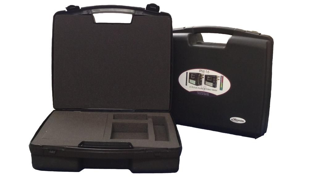
39 IPM-16-AUD-BRK-CAB IPM-16-ADAPTOR-CAB IPM-16-CASE IPM-16-EXT-CASE 39
AVMU2-BHD+/3G Audio monitoring Unit
 AVMU2-BHD+/3G Audio monitoring Unit Handbook Television Systems Limited. Vanwall Road, Maidenhead, Berkshire, SL6 4UB Telephone +44 (0)1628 676200, FAX +44 (0)1628 676299 AVMU2-BHD+/3G 1 ISSUE 3 SAFETY
BM-A1-E16SHD V2.2. Manual BM-A1-E16SHD. 16 Channel Digital Audio Monitor. User s Guide. Page 1
 BM-A1-E16SHD V2.2 Manual BM-A1-E16SHD 16 Channel Digital Audio Monitor User s Guide Page 1 BEL (Digital Audio) Ltd., has made every effort to ensure the accuracy of information contained within this document,
AMU1-BHD+ Audio monitoring Unit
 AMU1-BHD+ Audio monitoring Unit Handbook TSL Vanwall Road, Maidenhead, Berkshire, SL6 4UB Telephone +44 (0)1628 676200, FAX +44 (0)1628 676299 AMU1-BHD+-6 1 ISSUE 6 SAFETY Installation. Unless otherwise
C8491 C8000 1/17. digital audio modular processing system. 3G/HD/SD-SDI DSP 4/8/16 audio channels. features. block diagram
 features 4 / 8 / 16 channel LevelMagic2 SDI-DSP with level or loudness (ITU-BS.1770-1/ ITU-BS.1770-2, EBU R128) control 16 channel 3G/HD/SD-SDI de-embedder 16 in 16 de-embedder matrix 16 channel 3G/HD/SD-SDI
BM- AV1- E16SHD Manual BM-AV1-E16SHD. 16 Channel Digital Audio Monitor. User s Guide. Version /01/2013. Version 2.
 Manual BM-AV1-E16SHD 16 Channel Digital Audio Monitor User s Guide Version 2.1 14/01/2013 Version 2.1 Page 1 BEL (Digital Audio) Ltd., has made every effort to ensure the accuracy of information contained
AMU2-2MHD+ Audio monitoring Unit
 AMU2-2MHD+ Audio monitoring Unit Handbook TSL Vanwall Road, Maidenhead, Berkshire, SL6 4UB Telephone +44 (0)1628 676200, FAX +44 (0)1628 676299 AMU2-2MHD+-6 1 ISSUE 5 SAFETY Installation. Unless otherwise
Sound Measurement. V2: 10 Nov 2011 WHITE PAPER. IMAGE PROCESSING TECHNIQUES
 www.omnitek.tv IMAGE PROCESSING TECHNIQUES Sound Measurement An important element in the assessment of video for broadcast is the assessment of its audio content. This audio can be delivered in a range
User s Guide Version /01/2012
 BM- A2-16SHD 2012 BM-A2-16SHD 16 Channel Digital Audio Monitor User s Guide Version 1.0 01/01/2012 Version 1.0 Page 1 BEL (Digital Audio) Ltd., has made every effort to ensure the accuracy of information
DK Meter Audio & Loudness Metering Complete. Safe & Sound
 DK Meter Audio & Metering Complete Safe & Sound DK Meter at a glance Complete Audio & one-box metering Hassle-free Flexibility plug, preset and play High Quality Tools, yet outstanding value for money
Data Sheet SurroundMonitor Series
 Data Sheet Series 1 Overview 2 1 1 2 Remote Display 30010 (optional) 8-channel Multistandard PPM Surround Sound Analyzer Loudness Loudness Leq LRA PPM Dialnorm Vectorscope Correlator RtA Downmix AeS3 Status
BM-A2-4SHD MKII. Ver Channel Digital Audio Monitor. User s Guide. Page 1
 BM-A2-4SHD MKII BM-A2-4SHD MKII 4 Channel Digital Audio Monitor User s Guide Page 1 BEL (Digital Audio) Ltd., has made every effort to ensure the accuracy of information contained within this document,
BM-A1-2SHD MKII. Ver1.1 BM-A1-2SHD MKII. 2 Channel Digital Audio Monitor. User s Guide. Page 1
 BM-A1-2SHD MKII BM-A1-2SHD MKII 2 Channel Digital Audio Monitor User s Guide Page 1 BEL (Digital Audio) Ltd., has made every effort to ensure the accuracy of information contained within this document,
Table of Contents FCC COMPLIANCE STATEMENT... 4 WARNINGS AND PRECAUTIONS... 4 WARRANTY... 5 STANDARD WARRANTY... 5 TWO YEAR WARRANTY... 5 DISPOSAL...
 1 Table of Contents FCC COMPLIANCE STATEMENT... 4 WARNINGS AND PRECAUTIONS... 4 WARRANTY... 5 STANDARD WARRANTY... 5 TWO YEAR WARRANTY... 5 DISPOSAL... 6 1. INTRODUCTION... 7 FEATURES... 7 2. CONNECTIONS
S7H-DK S7H 7" High Bright Monitor Deluxe Kit
 S7H-DK S7H 7" High Bright Monitor Deluxe Kit QUICKSTART GUIDE What s Included 1 x S7H Monitor 1 x Camera Shoe Mount 1 x Neoprene Sleeve 1 x Mini-XLR to P-TAP Cable 2 x DV Battery Plate 1 x DV Battery 1
AMU2-8HD+ & 3G Audio Monitoring Units Handbook TSL Vanwall Road, Maidenhead, Berkshire, SL6 4UB
 AMU2-8HD+ & 3G Audio Monitoring Units Handbook TSL Vanwall Road, Maidenhead, Berkshire, SL6 4UB Telephone +44 (0)1628 676200, FAX +44 (0)1628 676299 AMU2-8HD+/3G 1 Issue 1 SAFETY Installation. Unless otherwise
SingMai Electronics SM06. Advanced Composite Video Interface: HD-SDI to acvi converter module. User Manual. Revision 0.
 SM06 Advanced Composite Video Interface: HD-SDI to acvi converter module User Manual Revision 0.4 1 st May 2017 Page 1 of 26 Revision History Date Revisions Version 17-07-2016 First Draft. 0.1 28-08-2016
NAB 2013 PRODUCT CATALOGUE
 NAB 2013 PRODUCT CATALOGUE QUAD-SPLIT / MULTI-VIEWERS DOWN UP CROSS CONVERTERS AUDIO MONITORING TEST PATTERN GENERATORS AES VU VU EXTENDED BBC EBU DIN NORDIC ABOUT US Comming Soon DECIMATOR DESIGN (aka
AM-4 Audio Monitor. Videoquip Research Limited 595 Middlefield Road, Unit #4 Scarborough, Ontario, Canada. MIV 3S2
 AM-4 Audio Monitor Videoquip Research Limited 595 Middlefield Road, Unit #4 Scarborough, Ontario, Canada. MIV 3S2 (416) 293-1042 1-888-293-1071 www.videoquip.com AM-4 4 channel Analog, AES3 Digital, SDI
Part 2. LV5333 LV5381 LV5382 LV7390 LV7770 LV7330 LV5838 LT4610 LT4600 LT4446 LT4100 LT4110 Accessories
 Part 2 LV5333 LV5381 LV5382 LV7390 LV7770 LV7330 LV5838 LT4610 LT4600 LT4446 LT4100 LT4110 Accessories LT4610SER01 OPTION LTC IN/OUT GPS IN CW IN AES/EBU/OUT SILENCE OUT WCLK OUT ETHERNET GENLOCK
Model 7600 HD/SD Embedder/ Disembedder Data Pack
 Model 7600 HD/SD Embedder/ Disembedder Data Pack E NSEMBLE D E S I G N S Revision 2.1 SW v2.0.1 This data pack provides detailed installation, configuration and operation information for the 7600 HD/SD
Model 7130 HD Downconverter and Distribution Amplifier Data Pack
 Model 7130 HD Downconverter and Distribution Amplifier Data Pack E NSEMBLE D E S I G N S Revision 1.0 SW v1.0 www.ensembledesigns.com 7130-1 Contents MODULE OVERVIEW 3 Audio Handling 3 Control 3 Metadata
SX7. Saga 7" Super Bright HDMI/3G-SDI Field Monitor with 3D-LUTs. Quick Start Guide. What s Included CHECKED BY
 SX7 Quick Start Guide Saga 7" Super Bright HDMI/3G-SDI Field Monitor with 3D-LUTs What s Included 1 x Saga X7 Monitor 1 x V-Mount Plate (Attached) 1 x Mini-XLR to P-TAP Cable 1 x Dual Sony L Battery Adapter
IQDEC01. Composite Decoder, Synchronizer, Audio Embedder with Noise Reduction - 12 bit. Does this module suit your application?
 The IQDEC01 provides a complete analog front-end with 12-bit composite decoding, synchronization and analog audio ingest in one compact module. It is ideal for providing the bridge between analog legacy
C8000. switch over & ducking
 features Automatic or manual Switch Over or Fail Over in case of input level loss. Ducking of a main stereo or surround sound signal by a line level microphone or by a pre recorded announcement / ad input.
SDI2SDI-S. With Genlock User Guide. Rev1.1. JMC Systems Engineering AB
 SDI2SDI-S With Genlock User Guide info@jmc.se Rev1.1 Content Feature... 3 Front Panel... 4 Rear Panel... 4 DipSwitch/LED Control... 5 Genlock Mode... 8 Installation... 9 Package Contents... 9 Specifications...
Manual Version Ver 1.0
 The BG-3 & The BG-7 Multiple Test Pattern Generator with Field Programmable ID Option Manual Version Ver 1.0 BURST ELECTRONICS INC CORRALES, NM 87048 USA (505) 898-1455 VOICE (505) 890-8926 Tech Support
CEDAR Series. To learn more about Ogden CEDAR series signal processing platform and modular products, please visit
 CEDAR Series The CEDAR platform has been designed to address the requirements of numerous signal processing modules. Easily-installed components simplify maintenance and upgrade. To learn more about Ogden
VXF7 QUICKSTART GUIDE. 7" 4K Full HD HDMI/3G-SDI On-Camera Monitor
 VXF7 QUICKSTART GUIDE 7" K Full HD HDMI/G-SDI On-Camera Monitor What s Included x VXF7 Monitor x AC Adapter x Camera Shoe Mount (SM-0) x Screen Cleaning Wipe x Screen Protector x Sunhood x Canon E6 Battery
DH7-DK QUICKSTART GUIDE. DH7 4K Support HDMI On-Camera Field Monitor Deluxe Kit
 DH7-DK QUICKSTART GUIDE DH7 4K Support HDMI On-Camera Field Monitor Deluxe Kit What s Included 1 x DH7 Monitor 1 x AC Adapter 1 x Camera Shoe Mount 1 x Screen Cleaning Wipe 1 x Screen Protection Film 1
SingMai Electronics SM06. Advanced Composite Video Interface: DVI/HD-SDI to acvi converter module. User Manual. Revision th December 2016
 SM06 Advanced Composite Video Interface: DVI/HD-SDI to acvi converter module User Manual Revision 0.3 30 th December 2016 Page 1 of 23 Revision History Date Revisions Version 17-07-2016 First Draft. 0.1
IQBSFR AES/EBU Digital Audio ReMapper with Stereo Combiner and Gain Control
 IQBSFR AES/EBU Digital Audio ReMapper with Stereo Combiner and Gain Control C Module Description The IQBSFR accepts two isosynchronous AES/EBU inputs (4 input subframes). Digital audio sample rates of
3G/HD/SD dual channel audio embedder/de-embedder
 3G/ dual channel audio embedder/de-embedder Dual channel audio embedder/de-embedder, with two independent video channels Being dual channel makes the audio embedder/de-embedder perfect for those pricesensitive
HDB
 GDB990-950-900-550-500 HDB990-950-900-550-500 3Gb/s, HD, SD digital or analog audio de-embedder with TWINS dual A Synapse product COPYRIGHT 2012 AXON DIGITAL DESIGN BV ALL RIGHTS RESERVED NO PART OF THIS
MD DUCC FIRMWARE VERSION 1.7 SETTINGS
 MD DUCC FIRMWARE VERSION 1.7 SETTINGS The latest USB Control Software and Specifications for this product can be downloaded at: www.decimator.com/specs POWER LED Green = Menu Value are displayed on LED
HDX6811N/HDX6812N High-definition Digital Audio De-embedder USER MANUAL
 HDX6811N/HDX6812N High-definition Digital Audio De-embedder USER MANUAL Product Information Model: HDX6811N/HDX6812N High-definition Digital Audio De-embedder Version: V010001 Release Date: May 22th, 2012
C / C / C Scaling with Speed and Agility
 C2-2855 / / Scaling with Speed and Agility A new generation of Scalers tvone s evolutionary development of our renowned CORIO 2 scaler technology continues to provide commercial integrators with unsurpassed
3Gb/s, HD, SD 16ch digital audio embedder with embedded domain audio shuffler, mixer and framesync COPYRIGHT 2018 AXON DIGITAL DESIGN BV
 3Gb/s, HD, SD 16ch digital audio embedder with embedded domain audio shuffler, mixer and framesync A Synapse product COPYRIGHT 2018 AXON DIGITAL DESIGN BV ALL RIGHTS RESERVED NO PART OF THIS DOCUMENT MAY
USER MANUAL. VP-435 Component / UXGA HDMI Scaler MODEL: P/N: Rev 13
 KRAMER ELECTRONICS LTD. USER MANUAL MODEL: VP-435 Component / UXGA HDMI Scaler P/N: 2900-000262 Rev 13 Contents 1 Introduction 1 2 Getting Started 2 2.1 Achieving the Best Performance 2 2.2 Safety Instructions
Simple all-in-one design style with front stereo speakers and natural ventilation system
 LMD-B170 17-inch cost-effective, lightweight basic grade Full HD LCD monitor for versatile use Overview Lightweight and slim Full HD (1920 x 1080) LMD-B Series monitor with an excellent cost-performance
AM-xx. In-Picture Audio Meter and Alarm System
 AM-xx In-Picture Audio Meter and Alarm System User s Guide Version 0.9BB 07/01/2009 Chromatec AM-xx Michael Stevens & Partners Ltd. has made every effort to ensure the accuracy of information contained
AX20. Atlas 19.5" 3G-SDI/HDMI Field and Studio Monitor with 3D LUTs & Scopes. Quick Start Guide. What s Included CHECKED BY
 AX20 Quick Start Guide Atlas 19.5" 3G-SDI/HDMI Field and Studio Monitor with 3D LUTs & Scopes What s Included 1 x Atlas 19.5" Monitor 1 x AC Adapter 1 x Sunhood CHECKED BY AX20 FRONT 1920 x 1080 19.5 inch
TECHNICAL MEDIA SPECIFICATION ON THE FILE BASED SUBMISSION OF MATERIALS TO BE AIRED
 TECHNICAL MEDIA SPECIFICATION ON THE FILE BASED SUBMISSION OF MATERIALS TO BE AIRED 2015.12.11 Contents 1. Introduction... 3 2. Material File Format... 4 3. Video properties... 6 4. Audio properties...
SAFETY. Unless otherwise stated TSL equipment may be installed at any angle or position within an operating temperature range of 5-30 C.
 SAFETY Installation. Unless otherwise stated TSL equipment may be installed at any angle or position within an operating temperature range of 5-30 C. All TSL equipment conforms to the EC Low Voltage Directive:
C8000. sync interface. External sync auto format sensing : AES, Word Clock, Video Reference
 features Standard sync module for a frame Internal sync @ 44.1 / 48 / 88.2 / 96kHz External sync auto format sensing : AES, Word Clock, Video Reference Video Reference : Black Burst (NTSC or PAL) Composite
Data Sheet SurroundControl Series
 Data Sheet SurroundControl 00 Series Overview Remote Control 000 SurroundControl 00 Remote Display 000 (optional) -ch. Monitoring Controller Surround Sound Analyzer Loudness Loudness Leq LRA PPM Dialnorm
Kaleido-Alto Kaleido-Quad Multi-Image Display Processor
 Kaleido-Alto Kaleido-Quad Multi-Image Display Processor Installation Manual M791-4200-104 21 Jan 2008 Miranda Technologies Inc. 3499 Douglas-B.-Floreani St-Laurent, Québec, Canada H4S 1Y6 Tel. 514-333-1772
3G/HD/SD audio embedder/de-embedder
 3G/ audio embedder/de-embedder is a very powerful embedding/ de-embedding product: working with 3Gb/s, HD and SD sources and providing flexible embedding and de-embedding of external audio. Using piggybacks
HD/SD-SDI TO VGA CONVERTER. DAC-60 Quick Start Guide.
 HD/SD-SDI TO VGA CONVERTER DAC-60 Quick Start Guide www.datavideo.com Warranty Standard Warranty Datavideo equipment is guaranteed against any manufacturing defects for one year from the date of purchase.
SE GPI 27 SE-2200
 Contents Warranty... 3 Disposal... 3 Packing List... 4 Connection of SE-2200... 4 Main Unit Front Panel... 5 Main Unit - Rear Panel... 5 Rear Panel Connections... 6 Control Panel... 8 Keyboard Controls...
7 3G -SDI Monitor w/ Signal Conversion QUICKSTART GUIDE
 What s included x Monitor x AC Adapter x Camera Shoe Mount (SM-0) x DV Battery Plate (Check one) Checked by DV BATTERY PLATES -: Canon 900, Sony L, Panasonic D Battery Plates VX7 c-: Canon E6, Nikon EL,
SDI-HDSDXPRO. USER MANUAL Version 1.1
 USER MANUAL Version 1.1 Index Description... 3 Features... 3 Connection Diagram... 4 Front Panel... 5 Rear Panel... 5 Dip Switch... 6 EDID Leaning... 7 Specifications... 8 Firmware Upload... 9 Update List...
RB-DSD8. 8 Channel Silence Switcher. Catalogue
 RB-DSD8 8 Channel Silence Switcher 2016 Catalogue RB-DSD8 8 Channel Silence Switcher Category: Synchronisers, Delays & Silence Detectors. Product Function: A multi channel (4 stereo) silence detector which
Operating Instructions
 Broadcast A/V Division Model No. M-LYNX-702W Dual 7 High Resolution Rack Mount Display with Waveform Operating Instructions V.1.0 Table of Contents 1. PRODUCT DESCRIPTION... 3 2. MENU SETTING... 6 3. SPECIFICATIONS...
MADI-xx. MADI converter and router networkable multi-channel audio monitoring system
 MADI-xx MADI converter and router networkable multi-channel audio monitoring system User s Guide Version 0.8 07/01/2009 Chromatec MADI-xx Michael Stevens & Partners Ltd. has made every effort to ensure
There is a button to select either the AES/EBU or S/PDIF input for the D/A converter, which is located on the rear panel.
 4 RB-DAC1 Digital to Analogue Converter Introduction Fig 4-1: RB-DAC1 Front Panel Using 24 bit, 96kHz capable devices, the RB-DAC1 Digital to Analogue Converter is a 1U rack-mount which produces a stereo
Broadcast A/V Division M-LYNX-702 V.3. Dual 7 LCD Display. User Manual
 Broadcast A/V Division M-LYNX-702 V.3 Dual 7 LCD Display User Manual 1. Package Includes Table of Contents 1. Package Includes Table of Contents 01 02 One M-LYNX-702 Monitor One universal AC power adapter
Models 5360 and 5365 Four Channel Analog to Digital Video Converters and Embedders Data Pack
 Models 5360 and 5365 Four Channel Analog to Digital Video Converters and Embedders Data Pack E NSEMBLE D E S I G N S Revision 1.3 SW v2.2.1 This data pack provides detailed installation, configuration
Broadcast A / V Division M-LYNX-702 V.3. Dual 7 LCD Display. User Manual
 Broadcast A / V Division M-LYNX-702 V.3 Dual 7 LCD Display User Manual Table of Contents Table of Contents 1. Package Includes 2. Product Description 2.1 Front Panel 2.2 Rear Panel Connections 3. On-Screen
CORIO master C3-540 Series
 Key Features Manage up to 4 independent video walls Uses CORIOgrapher; simple, powerful software interface Universal DVI Inputs/Outputs: (HDMI/CV/YC/RGB/YPbPr) SDI Inputs/Outputs: SD/HD-SDI/3G-SDI to 1080p60
HD/SD-SDI TO VGA CONVERTER. DAC-60 Quick Start Guide.
 HD/SD-SDI TO VGA CONVERTER DAC-60 Quick Start Guide www.datavideo.com Warranty Standard Warranty Datavideo equipment is guaranteed against any manufacturing defects for one year from the date of purchase.
DH5e-V2. Delta 5 On-Camera 4K HDMI Monitor with 3D LUTs. Quick Start Guide. What s Included
 DH5e-V2 Quick Start Guide Delta 5 On-Camera 4K Monitor with 3D LUTs What s Included 1 x DH5e-V2 Monitor 1 x L Series Battery Plate 1 x AC Adapter 1 x Screen Cleaning Wipe 1 x Screen Protection Film 1 x
AC182A 8 Input x 8 Output S-Video Matrix Switch with Audio
 Heading AC180A 8 Input x 8 Output Composite Video Matrix Switch with Audio MARCH 2005 AC180A AC182A AC182A 8 Input x 8 Output S-Video Matrix Switch with Audio CUSTOMER SUPPORT INFORMATION Order toll-free
COZI TV: Commercials: commercial instructions for COZI TV to: Diane Hernandez-Feliciano Phone:
 COZI TV: Commercials: Email commercial instructions for COZI TV to: cozi_tv_traffic@nbcuni.com Diane Hernandez-Feliciano Phone: 212-664-5347 Joseph Gill Phone: 212-664-7089 Billboards: Logo formats: jpeg,
Model 7940 SD Aspect Ratio Converter Data Pack
 Model 7940 SD Aspect Ratio Converter Data Pack E NSEMBLE D E S I G N S Revision 1.3 SW v2.3.3 This data pack provides detailed installation, configuration and operation information for the 7940 SD Aspect
OPERATING GUIDE. HIGHlite 660 series. High Brightness Digital Video Projector 16:9 widescreen display. Rev A June A
 OPERATING GUIDE HIGHlite 660 series High Brightness Digital Video Projector 16:9 widescreen display 111-9714A Digital Projection HIGHlite 660 series CONTENTS Operating Guide CONTENTS About this Guide...
AES-402 Automatic Digital Audio Switcher/DA/Digital to Analog Converter
 Broadcast Devices, Inc. AES-402 Automatic Digital Audio Switcher/DA/Digital to Analog Converter Technical Reference Manual Broadcast Devices, Inc. Tel. (914) 737-5032 Fax. (914) 736-6916 World Wide Web:
Routing Swichers 248
 Routing Swichers 248 BVG-1500...248 TIME CODE READER BVG-1600...250 TIME CODE GENERATOR BVX-10/10P...252 COMPONENT COLOR CORRECTOR BVX-D10...254 DIGITAL COLOR CORRECTOR BVR-D10/D11...256 REMOTE CONTROL
DK METER User Manual. DK METER Audio & Loudness Metering Complete
 DK METER User Manual DK METER Audio & Loudness Metering Complete 1 INTRODUCTION... 4 BEFORE YOU BEGIN... 4 ABOUT THIS MANUAL... 4 OTHER IMPORTANT NOTES... 5 QUICK GUIDE... 6 IF YOU JUST WANT TO GET GOING...
yellobrik Reference Manual P MV G/HD/SD Quad Split Multiviewer Revision 1.1 March 2016 Broadcast Television Equipment
 yellobrik Reference Manual P MV 1841 3G/HD/SD Quad Split Multiviewer Revision 1.1 March 2016 LYNXTechnik AG Broadcast Television Equipment This Manual Supports Device Revisions: P MV 1841 Firmware Revision
C8188 C8000 1/10. digital audio modular processing system. 4 Channel AES/EBU I/O. features. block diagram. 4 balanced AES inputs
 features 4 balanced AES inputs Input Sample Rate Converters (SRC) 4 balanced AES outputs Relay bypass for pairs of I/Os Relay wait time after power up Master mode (clock master for the frame) 25pin Sub-D,
Model 6010 Four Channel 20-Bit Audio ADC Data Pack
 Model 6010 Four Channel 20-Bit Audio ADC Data Pack Revision 3.1 SW v1.0.0 This data pack provides detailed installation, configuration and operation information for the Model 6010 Four Channel 20-bit Audio
CORIO master C3-540 Series CORIO 3 Technology C3-540 CORIO master offers a new, more efficient approach to building video systems.
 C3-540 CORIO master offers a new, more efficient approach to building video systems. Using TV One s Remotely latest CORIO controlled 3 technology, version it gives the user access to new levels of video
DH5e QUICKSTART GUIDE. 5" 4K Support HDMI On-Camera Field Monitor w/ Touch Screen
 DH5e QUICKSTART GUIDE 5" 4K Support On-Camera Field Monitor w/ Touch Screen What s Included 1 x DH5e Monitor 1 x AC Adapter 1 x Camera Shoe Mount 1 x Screen Cleaning Wipe 1 x Screen Protection Film 1 x
HD/SD 12-CHANNEL PORTABLE VIDEO STUDIO HS-2850 ( 8 / 12 CHANNEL ) Instruction manual
 Instruction manual") HD/SD 12-CHANNEL PORTABLE VIDEO STUDIO HS-2850 ( 8 / 12 CHANNEL ) Instruction manual Table of Contents WARNINGS AND PRECAUTIONS... 4 WARRANTY... 5 STANDARD WARRANTY... 5 THREE YEAR WARRANTY... 5 DISPOSAL...
HD/SD 12-CHANNEL PORTABLE VIDEO STUDIO HS-2850 ( 8 / 12 CHANNEL ) Instruction manual Table of Contents WARNINGS AND PRECAUTIONS... 4 WARRANTY... 5 STANDARD WARRANTY... 5 THREE YEAR WARRANTY... 5 DISPOSAL...
C / C / C Scaling with Speed and Agility
 / / Scaling with Speed and Agility A new generation of Scalers tvone s evolutionary development of our renowned CORIO 2 scaler technology continues to provide commercial integrators with unsurpassed image
User Manual AES-MUX. Multichannel digital audio to fibre.
 User Manual AES-MUX Multichannel digital audio to fibre. Network Electronics ASA Thorøya Sandefjord, Norway Phone: +47 33 48 99 99 Fax: +47 33 48 99 98 e-mail: support@network-electronics.com www.network-electronics.com
RMS 8424S Quick Start
 VIEWSIZE THE WORLD RMS 8424S Quick Start Standard 4 unit rack mount size 8 inch LCD 2 1024 3 (RGB) 600 16:9 / 4:3 adjustable SDI/HDMI embedded audio output via 3.5mm earphone socket Support SDI/DVI audio
C8000. LevelMagic2 SDI-DSP (international standards selectable) loudness control
 loudness control") Features LevelMagic2 SDI-DSP (international standards selectable) loudness control 4 optional 8 or 16 audio channels Optional surround processing Fail over and surround upmix 16 channel 3G/HD/SD-SDI de-embedder
Features LevelMagic2 SDI-DSP (international standards selectable) loudness control 4 optional 8 or 16 audio channels Optional surround processing Fail over and surround upmix 16 channel 3G/HD/SD-SDI de-embedder
VC100XUSB-Pro Installation Guide
 http://www.ems-imaging.com VC100XUSB-Pro Installation Guide Please contrast parts list and parts in package to confirm that there is no lack of any parts. Parts List Parts Number VC100XUSB-Pro capture
YSC -HD-AK1 HDMI / HD-SDI
 Remote Head Kamera 1/2.7 CMOS 2.14 Megapixel Sensor image memory Video Output 1 HDMI Video Output 2 HD-SDI Video Output 3 HD-SDI signal system 1080p/30fps YSC-HD-AK1 HDMI / HD-SDI POWER HDMI HD-SDI USB
Kramer Electronics, Ltd. USER MANUAL. Model: VS x 1 Sequential Video Audio Switcher
 Kramer Electronics, Ltd. USER MANUAL Model: VS-120 20 x 1 Sequential Video Audio Switcher Contents Contents 1 Introduction 1 2 Getting Started 1 2.1 Quick Start 2 3 Overview 3 4 Installing the VS-120 in
HD/SD 12-CHANNEL PORTABLE VIDEO STUDIO HS-2850 ( 8 / 12 CHANNEL ) Instruction manual
 Instruction manual") HD/SD 12-CHANNEL PORTABLE VIDEO STUDIO HS-2850 ( 8 / 12 CHANNEL ) Instruction manual Table of Contents WARNINGS AND PRECAUTIONS... 4 WARRANTY... 5 STANDARD WARRANTY... 5 THREE YEAR WARRANTY... 5 DISPOSAL...
HD/SD 12-CHANNEL PORTABLE VIDEO STUDIO HS-2850 ( 8 / 12 CHANNEL ) Instruction manual Table of Contents WARNINGS AND PRECAUTIONS... 4 WARRANTY... 5 STANDARD WARRANTY... 5 THREE YEAR WARRANTY... 5 DISPOSAL...
Kramer Electronics, Ltd. USER MANUAL. Models: VS-162AV, 16x16 Audio-Video Matrix Switcher VS-162AVRCA, 16x16 Audio-Video Matrix Switcher
 Kramer Electronics, Ltd. USER MANUAL Models: VS-162AV, 16x16 Audio-Video Matrix Switcher VS-162AVRCA, 16x16 Audio-Video Matrix Switcher Contents Contents 1 Introduction 1 2 Getting Started 1 3 Overview
W-2x2 2x2, 1x3 or 1x4 Video Wall. Low Resolution. Monitor Output. CATx Extender Output) Low Resolution. Monitor Output (HDMI, DVI
 Low Resolution. Monitor Output (HDMI, DVI") WALL Video Walls Plug and play - no software required for operation Color temperature adjustments Pure hardware architecture, not a PC Can be configured in a x mode to be used with a x 4K monitor Can be
WALL Video Walls Plug and play - no software required for operation Color temperature adjustments Pure hardware architecture, not a PC Can be configured in a x mode to be used with a x 4K monitor Can be
DSA-1. The Prism Sound DSA-1 is a hand-held AES/EBU Signal Analyzer and Generator.
 DSA-1 The Prism Sound DSA-1 is a hand-held AES/EBU Signal Analyzer and Generator. The DSA-1 is an invaluable trouble-shooting tool for digital audio equipment and installations. It is unique as a handportable,
Model 4455 ASI Serial Digital Protection Switch Data Pack
 Model 4455 ASI Serial Digital Protection Switch Data Pack Revision 1.5 SW v2.2.11 This data pack provides detailed installation, configuration and operation information for the 4455 ASI Serial Digital
Operating Instructions
 Marshall Electronics Broadcast A/V Division Model No. VSW-2200 4-Input Seamless SDI A/V Switcher Operating Instructions Table of Contents 1. Overview... 2. Features.... Package Contents... 4. Specifications...
OWNERS MANUAL LUNATEC V3 MICROPHONE PREAMPLIFIER AND A/D CONVERTER
 OWNERS MANUAL LUNATEC V3 MICROPHONE PREAMPLIFIER AND A/D CONVERTER LUNATEC 35 +48 35 +48 30 40 30 40 0 25 45 25 45 3 192 1 1 6 176.4 20 50 20 50 9 96 12 PEAK 88.2 55 55 RESET 48 10 60 2 10 60 2 21 44.1
OPERATION MANUAL. USF-402AADC Audio Analog Digital Converter. 1 st Edition
 OPERATION MANUAL USF-402AADC Audio Analog Digital Converter 1 st Edition Precautions Important Safety Warnings [Operation] Hazard [Transportation] Hazard [Circuitry Access] Do not operate the unit under
55-inch Class FULL HD LCD Display TH-55SF1HW
 Product specification (design and specification subject to change without notice) DISPLAY PANEL Screen Size (Diagonal) 54.6-inch (1387 mm) Panel type IPS / Edge-LED Aspect ratio 16:9 Effective Display
USER MANUAL. VP-426 HDMI-PC Scaler MODEL: P/N: Rev 4.
 USER MANUAL MODEL: VP-426 HDMI-PC Scaler P/N: 2900-300277 Rev 4 www.kramerav.com Contents 1 Introduction 1 2 Getting Started 2 2.1 Achieving the Best Performance 2 2.2 Safety Instructions 2 2.3 Recycling
DLM471S-5.1 MULTICHANNEL AUDIO LEVEL MASTER OPERATION MANUAL IB B. (Mounted in RMS400 Rack Mount & Power Supply) (One of 4 Typical Cards)
 (One of 4 Typical Cards)") DLM471S-5.1 (Mounted in RMS400 Rack Mount & Power Supply) MULTICHANNEL AUDIO LEVEL MASTER (One of 4 Typical Cards) OPERATION MANUAL IB6432-02B TABLE OF CONTENTS PAGE 1.0 GENERAL DESCRIPTION 2 2.0 INSTALLATION
DLM471S-5.1 (Mounted in RMS400 Rack Mount & Power Supply) MULTICHANNEL AUDIO LEVEL MASTER (One of 4 Typical Cards) OPERATION MANUAL IB6432-02B TABLE OF CONTENTS PAGE 1.0 GENERAL DESCRIPTION 2 2.0 INSTALLATION
VIDEO 101 LCD MONITOR OVERVIEW
 VIDEO 101 LCD MONITOR OVERVIEW This provides an overview of the monitor nomenclature and specifications as they relate to TRU-Vu industrial monitors. This is an ever changing industry and as such all specifications
MD-QUAD VERSION 3 1 to 4 Channel (3G/HD/SD)-SDI Multi-Viewer / Quad-Split with SDI and HDMI outputs Operating Manual for Firmware Version 2.
-SDI Multi-Viewer / Quad-Split with SDI and HDMI outputs Operating Manual for Firmware Version 2.") MD-QUAD VERSION 3 1 to 4 Channel (3G/HD/SD)-SDI Multi-Viewer / Quad-Split with SDI and HDMI outputs Operating Manual for Firmware Version 2.0 MD QUAD 3 FIRMWARE VERSION 2.0 SETTINGS Please note: MD QUAD
MD-QUAD VERSION 3 1 to 4 Channel (3G/HD/SD)-SDI Multi-Viewer / Quad-Split with SDI and HDMI outputs Operating Manual for Firmware Version 2.0 MD QUAD 3 FIRMWARE VERSION 2.0 SETTINGS Please note: MD QUAD
Headphones Boxes Sample rate converter Auto level takers Interboxes Digital Tone generator Digital headphones
 BLACK BOXES INDEX PAGE 2 3,4 5,6 7,8 9,10 11,12 TITLE Headphones Boxes Sample rate converter Auto level takers Interboxes Digital Tone generator Digital headphones The BCD Audio Black-box range provides
Cablecast Server. Setup Guide. c Tightrope Media Systems For Cablecast version Build 74
 Cablecast Server Setup Guide c Tightrope Media Systems For Cablecast version 6.1.2 Build 74 Printed July 22, 2016 1 Cablecast Server Setup 1.1 Prerequisites 1.2 Overview of Setup Thank you for purchasing
LCD Racks Monitor PRM-483A MULTI-CHANNEL LCD MONITOR
 LCD Racks Monitor PRM-483A MULTI-CHANNEL LCD MONITOR Contents PRM-483A Warnings... 3 Features... 4 Name & Function of Each Part... 5 OSD Menu Organization & Adjustment... 7 Other Functions... 14 System
Table of Contents FCC COMPLIANCE STATEMENT... 4 WARNINGS AND PRECAUTIONS... 4 WARRANTY... 5 DISPOSAL... 5 CHAPTER 1 INTRODUCTION...
 1 Table of Contents FCC COMPLIANCE STATEMENT... 4 WARNINGS AND PRECAUTIONS... 4 WARRANTY... 5 STANDARD WARRANTY... 5 TWO YEAR WARRANTY... 5 DISPOSAL... 5 CHAPTER 1 INTRODUCTION... 7 1.1 FEATURES... 7 1.2
User Manual. TCU/RCU RF Head Control Units. TCU/RCU Analogue 11/6/
 11/6/2009 www.elber.com elber@elber.it TCU/RCU RF Head Control Units User Manual Elber s.r.l.- Via Pontevecchio, 42W Phone +39-0185.35.13.33 16042 Carasco (GE) Italy Fax +39-0185.35.13.00 1 Sommario 2
VSG-401. Compact Video and Audio Signal Generator FEATURES
 Compact Video and Audio Signal Generator The new Videotek is a ½RU-wide, dual-link, 3G/HD/SD signal and sync generator. Part of the Videotek Compact Monitor Series, the unit is small in size and light