TRAFFIC SIGNAL DESIGN GUIDELINES
|
|
|
- Isabel Carpenter
- 5 years ago
- Views:
Transcription
1 TRAFFIC SIGNAL DESIGN GUIDELINES January, 2006
2 INDEX PLAN APPROVAL PROCESS 1 1. Designer Prequalification 1 2. Items Available from the County 1 3. Plan Submittals 1 4. Final Submittal 1 5. Checklist for Traffic Signal Plan Submittals 3 DESIGN GUIDELINES 4 1. Electric Service Installation 4 2. Traffic Signal Heads 4 3. Traffic Signal Head Placement 4 4. Pedestrian Signal Heads 5 5. Pedestrian Push-Buttons 5 6. Video Detection System (Complete Intersection) 5 7. Remote-Controlled Video System 6 8. Video Transmission System 6 9. Layer III (Network) Switch Layer II (Data Link) Switch Video Communications Cabinet Inductive Loop Detection Emergency Vehicle Preemption Detection Controllers Signal Posts Mast Arm Assemblies and Poles Handholes 9
3 18. Conduit in Ground Conduit Estimation Procedure Electrical Cables Electrical Cable Slack Foundations Temporary Traffic Signals Mast Arm Mounted Street Name Signs Pavement Marking Sidewalk Maintenance Vehicle Landing Space Street Lighting Traffic Control & Protection System Grounding of Traffic Signal Equipment Traffic Signal Interconnect Systems Railroad Coordination/Preemption Unique LCDOT Coded Pay Items 18 PLAN FORMAT General Cover Sheet Summary of Quantities Sheet Temporary Traffic Signal Plan Temporary Cable Plan Traffic Signal Installation/Modification/Modernization Plan Cable Plan, Schedule of Quantities & Phase Designation Diagram Interconnect Plan Interconnect Schematic and Schedule of Quantities 21
4 10. Other Sheets Specifications and Traffic Control and Protection Estimate of Cost 22 APPENDIX A - LEGENDS LCDOT Notes for Temporary Traffic Signals LCDOT Remove Existing Traffic Signal Equipment Notes LCDOT Existing Equipment to be Removed Legend LCDOT Temporary Traffic Signal Legend LCDOT Temporary Cable Plan Legend LCDOT Traffic Signal Legend LCDOT Cable Plan Legend LCDOT Interconnect Plan Legend LCDOT Interconnect Schematic Legend LCDOT Wattage Calculation Table APPENDIX B INTERSECTION DESIGN EXAMPLES Temporary Signal Plan #1 Temporary Signal Plan #2 Signal Plan #1: General Guidelines Signal Plan #2: T Intersection w/o Pedestrian Crossings Phase Diagrams #2: T Intersection w/o Pedestrian Crossings Signal Plan #3: T Intersection with Pedestrian Crossings Phase Diagrams #3: T Intersection with Pedestrian Crossings Signal Plan #4: Four-legged Intersection w/o Pedestrian Crossings Phase Diagrams #4: Four-legged Intersection w/o Pedestrian Crossings
5 Signal Plan #5: Four-legged Intersection with Pedestrian Crossings Phase Diagrams #5: Four-legged Intersection with Pedestrian Crossings APPENDIX C SAMPLE ESTIMATE OF COST, SIGNAL PLANS, AND DETAIL SHEETS Estimate of Cost Federally Funded Project Cover Sheet County Funded Project/Private Developer Cover Sheet Summary of Quantities Traffic Signal Modernization Plan (for intersection without a temporary signal) Cable Plan (for intersection without a temporary signal) Temporary Traffic Signal Installation Temporary Cable Plan Traffic Signal Modernization Plan Sheet 1 of 2 Traffic Signal Modernization Plan Sheet 2 of 2 Cable Plan Sequence of Operations Interconnect Plan Interconnect Schematic Mast Arm Mounted Street Name Signs Video System Schematic LCDOT Standard Traffic Signal Design Detail Sheets Typical Pavement Markings for County Highways Sheets IDOT District I Standard Traffic Signal Design Detail Sheets
6 PLAN APPROVAL PROCESS 1. Designer Prequalification The firm supplying plans to the Lake County Division of Transportation (LCDOT or County) must be prequalified with the Illinois Department of Transportation in Special Plans - Traffic Signals, and its signal design staff shall be familiar with the latest traffic signal design procedures used by the County. The firm s signal designer may schedule a preliminary meeting with the County Traffic Engineer to discuss project specific issues on projects involving complex designs. If requested by the County, the signal designer shall provide copies of their most recent traffic signal installation design and/or modification projects completed for projects in the County. Interaction between a traffic signal design firm and the County must be on a shared benefit basis. If, in the opinion of the County, the firm is attempting to design plans beyond the level of competence of its staff, the County may refuse further review until qualified assistance is acquired and approved. The firm is expected to provide interpretive assistance and revisions to their work up to and through the construction phase of the project. 2. Items AvailabIe from the County The following items are available in either electronic or hard copy format from the County upon request for use in the design process: LCDOT Traffic Signal Specifications. LCDOT Mast Arm Mounted Street Name Sign Sheet. LCDOT Standard Traffic Signal Design Detail Sheets. Typical Pavement Markings for County Highways Sheets. Existing Traffic Signal Plans or Samples. 3. Plan Submittals Two full-size sets of plans, specifications and cost estimate should be submitted along with the Checklist for Traffic Signal Plan Submittals (shown on page 3). After the first submittal, all subsequent submittals should include a letter with responses to review comments and the marked-up plans and specifications from the previous review. 4. Final Submittal Upon final plan approval, the County will request the final plan submittal be made by the Consultant. The final plan submittal should include the following items: 1
7 Checklist for Traffic Signal Plan Submittals (next page). One full-size reproducible (mylar) plan set, signed and sealed. Four full-size paper plan sets, signed and sealed. Four sets of specifications. Four copies of the Estimate of Cost, signed and sealed. CD containing MicroStation files for entire project. The names of the MicroStation files should include both of the street names at the intersection and the file type, for example: Cover Sheet Summary of Quantities Temporary Traffic Signal Plan Temporary Cable Plan Traffic Signal Installation Plan Traffic Signal Modification Plan Cable Plan Sequence of Operation Interconnect Plan Interconnect Schematic Mast Arm Mounted Street Name Signs Video Transmission System Schematic 01_Delany&Sunset to Grove_CVR 02_Delany&Sunset to Grove_SUM 03_Delany&Ryan_TMP 04_Delany&Ryan_TCB 05_Delany&Ryan_TSI 05_Delany&Ryan_MOD 06_Delany&Ryan_CAB 07_Delany&Ryan_SEQ 08_Delany&Sunset to Grove_INT 09_Delany&Sunset to Grove_SCM 10_Delany&Sunset to Grove_STN 11_Delany&Sunset to Grove_VID 5. Checklist The Checklist on the following page should be completed and submitted with each plan submittal. 2
8 CHECKLIST FOR TRAFFIC SIGNAL PLAN SUBMITTALS SUBMITTED TO: SUBMITTAL DATE: JOB: PERMIT / COUNTY / FEDERAL MAIN ROUTE: CROSS STREET: LIMITS OF DESCRIPTION: PROJECT: THIS IS THE: 1st 2nd 3rd 4th 5th or Final SUBMITTAL OF THIS PLANSET. SIGNAL PROJECT/PLANSET IS: Stand Alone Part of Roadway Improvement Planset Separate from Roadway Improvement Planset DESIGN FIRM FOR TRAFFIC SIGNAL PLANS: Designed by: Drawn by: Checked by: DESIGN FIRM FOR ROADWAY IMPROVEMENT PLANS: THE FOLLOWING ITEMS ARE INCLUDED WITH THIS SUBMITTAL: Roadway Improvement Plans Signed and Sealed Cover Sheet Signed and Sealed Cost Estimate Summary of Quantities Sheet Mast Arm Mounted Street Name Signs Traffic Signal Specifications Marked-up Plans from Previous Review Mylar Plans IDOT District 1 Standard Traffic Signal Design Detail Sheets LCDOT Standard Traffic Signal Design Detail Sheets LCDOT Typical Pavement Markings for County Highways Sheets Letter Responding to Previous Review Comments CD Containing MicroStation Files for Entire Project Yes No -- An Intersection Design Study has been completed for this intersection. Yes No -- These Plans are being submitted to IDOT for review and comment. Yes No -- Temporary Traffic Signals are required for these improvements. Yes No -- The Municipalities have been contacted regarding EVP equipment installation. Yes No LCDOT has received a copy of this correspondence. Yes No -- Electric Company has been contacted regarding Service Installation. Yes No LCDOT has received a copy of this correspondence. Yes No -- Telephone Company has been contacted regarding Phone Service. Yes No LCDOT has received a copy of this correspondence. OTHER:
9 DESIGN GUIDELINES 1. Electric Service Installation The designer shall contact the electric utility company regarding the electric service installation requirements or charges for the project. The County shall be copied on all written correspondence with the electric utility company. The name and phone number of the electric utility company representative shall be listed on the Cable Plan in the Wattage Calculation Table. If a new electric service location is required for the project, the designer should meet with the representative of the electric utility company in the field to verify the proposed location for the electrical service. If the total wattage for an existing traffic signal installation will be changing because of signal modifications, a copy of the new Wattage Calculation Table shall be sent to the electric utility company representative. The cable for the electric service shall be brought into the cabinet foundation using a 2 conduit. Either a Pole Mounted or a Ground Mounted Service Installation shall be specified for each new traffic signal. 2. Traffic Signal Heads All new or modernized traffic signal installations shall utilize Light Emitting Diode (LED) signal heads. All traffic signal heads used in permanent signal installations shall be either bracket mounted or mast arm mounted and the material type shall not be specified. All traffic signal sections shall have 12 lenses. All existing 8 lenses shall be removed and replaced. All mast arm mounted signal heads require louvered backplates. 3. Traffic Signal Head Placement A minimum of three signal heads for through traffic shall be provided on the far side of the intersection. At least one, and preferably two, of the signal faces required on the far side shall be located between two lines intersecting with the center of the approach lanes at the stop bar, one making an angle of approximately 20 degrees to the right of the center of the approach extended and the other making an angle of approximately 20 degrees to the left of center of the approach extended. If Mast Arms are proposed, two of the signal heads shall be mounted on the mast arm. If more than one through-lane exists for an approach, each mast arm mounted signal head shall be mounted in the center of the corresponding through-lane. 4
10 See Appendix B for additional guidance on traffic signal head placement for various lane configurations. 4. Pedestrian Signal Heads All new pedestrian signal heads shall display the international symbol for walk (walking person) and the international symbol for don t walk (raised paim) on the top section, and a countdown timer on the bottom section. Existing pedestrian signal heads that utilize text ( Don t Walk / Walk ) shall be removed and replaced. All pedestrian signal heads shall be bracket mounted. 5. Pedestrian Push-Buttons Pedestrian push-buttons shall be placed next to sidewalks or at locations convenient to crosswalks, according to current Americans with Disabilities Act (ADA) standards. Each push-button shall be shown on the Plan on the side of the mast arm or post where it is to be installed. Each pushbutton should be accompanied by a 5 x 7 sign, and the sign and its location shall also be shown on the Plan. See the General Example in Appendix B for proper pushbutton and sign placement. Two pushbuttons per corner shall be provided when two walk phases are available at that corner. The pushbuttons shall be mounted on separate posts/mast arms, and shall be a minimum of 10 feet apart. 6. Video Detection System (Complete Intersection) The Video Detection System (Complete Intersection) shall be called for in the plans on all new traffic signal installations and on some traffic signal modernizations, except when State or Federal funding is involved. The use of video detection in these cases shall be determined by the County Traffic Engineer. Video detection cameras should be shown on all County temporary traffic signals, and the cost of the Video Detection System shall be incidental to the cost of the temporary traffic signal. When installed on a permanent traffic signal installation, combination mast arms shall be used, and the video detection camera shall be located on the luminaire arm of the combination mast arm assembly. When installed on a temporary traffic signal installation, the camera shall be located on the wood pole. Detection zones should be shown on the plans when video detection cameras are used. The detection zone should be nearly as wide as the lane that it is in, and about 35 long, when located just behind the stop bar. When located at far-back detection areas, the zone should cover nearly the entire travel-way for the oncoming lanes and be about 12 long. If pavement marking for a turn-lane (arrow and ONLY ) is located within a proposed detection zone, the pavement marking should be removed and relocated to 50 behind the stop bar. 5
11 7. Remote-Controlled Video System The Remote-Controlled Video System (PTZ Camera) shall be called for in the plans on all new traffic signal installations and on some traffic signal modernizations, except when State or Federal funding is involved. The use of the PTZ Camera in these cases shall be determined by the County Traffic Engineer. The PTZ Camera shall be shown on all County temporary traffic signals, unless otherwise directed by the County Traffic Engineer, and the cost of the Remote-Controlled Video System shall be incidental to the cost of the temporary traffic signal. The PTZ Camera shall be installed on the pole of the combination mast arm assembly and pole, and should be located in the intersection quadrant that will provide the most visibility for both of the intersecting streets. The designer should field check the lines-of-sight to determine the best location for the PTZ Camera. 8. Video Transmission System The Video Transmission System allows the County to control the video detection cameras and PTZ camera(s) at an intersection or in a system via an ISDN connection. Either the Video Transmission System or the Layer III Switch shall be called for in the plans when video detection is used. The designer should assume the Layer III Switch will be used, unless otherwise directed by the County Traffic Engineer. Only one Video Transmission System is necessary for each interconnected traffic signal system. The Video Transmission System should be located at the same location as the Master Controller, and an ISDN phone line should be provided in addition to the regular phone line for the master controller. Besides the ISDN phone line, there is no other plan symbology for the Video Transmission System. In some instances, the County may wish to install the Video Transmission System in a cabinet other than the intersection traffic signal cabinet. When directed by the County Traffic Engineer, the Video Transmission System should be located in a Video Communications Cabinet. The Video Communications Cabinet should be shown on the plans next to the intersection traffic signal cabinet. 9. Layer III (Network) Switch The Layer III Switch allows the County to control the video detection cameras and PTZ camera(s) at an intersection or in a system via fiber optic interconnect cable. Either the Layer III Switch or the Video Transmission System shall be called for in the plans when video detection is used. The designer should assume the Layer III Switch will be used, unless otherwise directed by the County Traffic Engineer. One Layer III Switch can support up to seven Layer II Switches. If a system will have more than seven Layer II Switches, a second Layer III Switch should be considered for that system. The Layer III Switch and the Terminal Server should be located at the same intersection. 6
12 The Layer III Switch shall always be installed in a Video Communications Cabinet. The Video Communications Cabinet should be shown on the plans next to the intersection traffic signal cabinet. There is no plan symbology for the Layer III Switch, but there is for the Video Communications Cabinet. 10. Layer II (Data Link) Switch The Layer II Switch allows the County to control the video detection cameras and/or PTZ camera at an intersection via the Layer III Switch and fiber optic interconnect cable. The Layer II Switch shall be called for at all intersections in a traffic signal system in which a Layer III Switch is called for, unless otherwise directed by the County Traffic Engineer. The intersection where the Layer III Switch is located does not need a Layer II Switch. At stand-alone intersections, the use of a Layer II Switch shall be determined by the feasibility of installing fiber optic interconnect cable to that intersection from the nearest Layer III Switch. This shall be determined by the County Traffic Engineer on a case-by-case basis. There is no plan symbology for the Layer II Switch. The Layer II Switch shall be installed in the intersection traffic signal cabinet, which may be Type IV or Type V, unless otherwise directed by the County Traffic Engineer. 11. Video Communications Cabinet The Video Communications Cabinet shall be called for in the plans to house the Layer III Switch, and, in some instances, to house the Video Transmission System. The Video Communications Cabinet should be located next to the intersection cabinet in a manner that permits the doors of both cabinets to open completely. 12. Inductive Loop Detection On projects involving State or Federal funding, inductive loop detectors may be required. Please refer to IDOT District One s Traffic Signal Design Guidelines for guidance on inductive loop detector design. On County projects where existing loop detectors are being replaced with video detection, the far back loops on each approach may be retained as sampling loops and shall be combined on one lead-in cable. 13. Emergency Vehicle Preemption Detection Emergency Vehicle Preemption shall be installed for all new intersections, unless otherwise directed by the local agency. Under most conditions, a bi-directional light detector assembly will be adequate. Where mast arms are present, the detector shall be placed on the mast arm two feet to the right of the far left mast arm mounted signal. On intersection approaches which do not have mast arms, the designer shall field check the line-of-sight to determine the best location. Emergency vehicle light detectors must be mounted on 18-foot posts where mast arm mounting is not available. At larger intersections with dual left turn lanes, wide 7
13 medians, and/or three through-lanes, the detectors should be split. A separate light detector will be required for each approach. Confirmation beacons must be provided for each direction of emergency vehicle detection. The designer shall ensure that appropriate pay items are included in the plans (i.e., LIGHT DETECTOR, LIGHT DETECTOR AMPLIFIER). The pay item LIGHT DETECTOR AMPLIFIER shall be paid for on a basis of one each per intersection controller and shall provide operation for all movements required in the preemption phase sequence. 14. Controllers Actuated solid state digital controllers meeting the latest NEMA standards housed in a Type IV or Type V cabinet shall be specified for all new intersections, and where appropriate for modernized or modified intersections. The pay item FULL-ACTUATED CONTROLLER AND TYPE IV ( or V) CABINET shall be specified for these intersections. The pay item FULL-ACTUATED CONTROLLER AND TYPE V CABINET shall be specified for all intersections that include a local controller and master controller. The designer will be responsible for ensuring controller and master controller compatibility with existing equipment in the vicinity of the proposed design. In addition, the designer will be responsible for keeping abreast of the District s approved signal system manufacturers and their limitations (i.e., maximum number of system loops per master, maximum number of system loops per local, maximum number of controllers per master, maximum number of system loops per local, maximum number of controllers per master, special telemetry requirements for large systems, etc.) 15. Signal Posts Traffic signal posts shall be galvanized steel. All traffic signal posts should be placed a minimum of four feet behind the back of a barrier curb, or, If barrier curb does not exist, the post should be placed a minimum of ten feet behind the edge of pavement or two feet behind the edge of shoulder, whichever distance is greater. The following post heights should be used with bracket mounted traffic signal heads and other post mounted equipment: 3-Section Head 16 post. 4-Section Head 16 post. 5-Section Head 16 post. Emergency Vehicle Preemption Light Detector 18 post. Optically Programmed Signal Head 18 post. Pedestrian Signal Head or Pushbutton only 10 post. For new installations, decorative posts shall be used. The County has special pay item numbers assigned for the decorative posts. See page 18. 8
14 16. Mast Arm Assemblies and Poles Combination Mast Arm Assemblies and Poles shall be used at installations when video detection cameras are being installed. All mast arm poles shall be located at a minimum of six feet behind the back of barrier curb, or, if barrier curb does not exist, the mast arm poles shall be located at a minimum of ten feet behind the edge of pavement or two feet behind the edge of shoulder, whichever distance is greater. Steel mast arm poles shall be located to utilize a fourteen to fifty-five foot mast arm assembly. The mast arm lengths shall be in two foot, even increments up to fifty-four feet (i.e. 14, 16,... 52, 54, 55 ). The outer traffic signal head on a steel mast arm assembly is to be placed two feet in from end of the mast arm. For new installations, decorative mast arms shall be used. The County has special pay item numbers assigned for the decorative posts. See page Handholes All handholes shall be cast in place utilizing IDOT Standards and A double handhole shall be specified when eighteen or more cables enter a handhole and next to each controller cabinet. A handhole is required when there is a change in direction of any conduit run that is 90 or more. Conduit runs with a change in direction of 90 or less, but that occur over a long distance (i.e., large radii) may not require a handhole. Heavy-duty handholes shall be specified at all locations where vehicles could potentially drive over them, such as in the pavement or adjacent to shoulders. Heavy-duty handholes shall only be designed in the pavement when it is necessary to service inside lane loops. Up to two lanes of detection can be serviced from a handhole outside the pavement area, and this is preferred to placing a heavy-duty handhole in the pavement. Heavy-duty double handholes are not allowed. Interconnect handholes should be located as close to the right-of-way line as possible. Cross sections must be analyzed to ensure proper placement of interconnect handholes (i.e. outside drainage ditches). The maximum spacing for interconnect handholes is 300 feet when copper conductor cable is used and 600 feet when fiber optic cable is used. 18. Conduit in Ground All conduit shall be specified as conduit in ground, meaning it is not specified as pushed or trenched. All conduit shall be galvanized steel with the exception of the low voltage detector raceway located between the pavement and adjacent handholes, which should utilize plastic unit duct. 9
15 The telephone service cable shall have its own conduit entering the controller foundation directly. If the telephone service cable will be routed through the double handhole adjacent to the controller foundation, it shall be installed in a one inch unit duct through the double handhole to reduce electrical interference from the electrical cables in the handhole. The electrical service cable shall have its own conduit entering the controller foundation directly. The following conduit sizes shall be used: LOCATION SIZE Entering a Combination Mast Arm Assembly and Pole 3 Entering a regular Mast Arm 2 ½ Entering a Signal Post 2 ½ Telephone Service 2 Electrical Service 2 From Controller to Double Handhole (2) 4 Crossing four or more lanes of roadway 4 19 or more cables (2) 4 Ending at a Heavy-Duty Handhole servicing inside lane loops 2 Entering the railroad cabinet 2 Housing Interconnect cables only 2 Unit duct 1 10
16 CONDUIT ESTIMATION PROCEDURE 1. Find cable factor for each cable in conduit for which size is to be determined: CABLE FACTOR #14, 2C 1.00 #14, 3C 1.08 #14, 5C 1.64 #14, 7C 1.80 Fiber Optic Cable, No. 62.5/125 24F 1.80 Fiber Optic Cable, No. 62.5/125 36F 2.00 #2, 2C 4.00 #4, 2C 3.00 #6, 2C Pair, # Pair, # #20, 3C 0.50 #14, 1C 0.60 #10, 1C 0.50 #6, 1C C, # #16, 5 ½ Pair 1.80 #14, 3C, Railroad 1.08 Coaxial Cable Add together the factors for all cable in the conduit. 3. Add 1.00 to the sum from Step 2 to get the Total. 4. Using the Total found in Step 3, find the conduit size using the chart below: TOTAL CONDUIT SIZE New Signal Add Pedestrian Or Modify or Preemption 40% Full 50% Full < ¼ < ½ < < ½ < < ½ < < Check conduit size found in Step 4 with the minimum sizes to be used for particular conditions and change to minimum size if size found in Step 4 is smaller. CONDUIT MINIMUM SIZE Service Installation, Controller to RR Cabinet, Pedestrian Signal Post & Interconnect 2 Signal Post or Regular Mast Arm Foundation 2 ½ Combination Mast Arm Foundation 3 Handhole to Controller & Main Conduit Crossings 4 11
17 20. Electrical Cables The following electrical cables shall be used: ITEM 3-Section Signal Head 5-Section Signal Head Pedestrian Signal Head Pedestrian Pushbutton Video Detection Camera PTZ Camera CABLE No. 14, 5C No. 14, 7C No. 14, 3C No. 14, 2C No. 16, 6 Pair No. 14, 3C, No. 20, 3C & Coaxial Cable Luminaire 600V (EPR-Type RHW) 2-1/C No. 10 Detector Loop No. 14, 1 Pair Electric Service No. 6, 2C EVP Light Detector No. 20, 3C, Twisted, Shielded Confirmation Beacon No. 14, 3C L.E.D. Street Name Sign No. 14, 2C L.E.D. Blankout Sign No. 14, 3C Microwave Detector No. 14, 2C Railroad Interconnect No. 14, 3C Interconnect 24 Fiber or 36 Fiber Tracer Cable No. 14, 1C Video Communications Cabinet (for Video Transmission System) Video Communications Cabinet (for Layer III Switch) 24 Fiber or 36 Fiber, No. 6, 2C & Coaxial Cable 24 Fiber or 36 Fiber & Ethernet Cable 22. Electrical Cable Slack The following slack and vertical lengths shall be used when calculating cable lengths: ITEM SLACK Handhole 6.5 Double Handhole 13 ITEM VERTICAL Foundations 3.5 Mast Arm Mounted Item 20 + length on arm Bracket Mounted Traffic or Pedestrian Signal Head 13 L.E.D. Blankout Sign on Signal Post 18 EVP on Signal Post 18 Pedestrian Pushbutton 4 Electric Service 13.5 Luminaire 45 Video Detection Camera 45 PTZ Camera 40 12
18 23. Foundations The following foundation types and depths shall be used for concrete foundations: ITEM TYPE DEPTH Signal Posts Type A 4 Controller Cabinet and Video Communications Cabinet Type D 4 Controller Cabinet with UPS attached Type D (Special) 4 Non-combination mast arms less than 40 long Type E (30 ) 15 All other mast arms and combination mast arms Type E (36 ) Temporary Traffic Signals The installation of temporary traffic signals at locations with existing traffic signals is required in most cases where the existing signal equipment is being disrupted by construction or where the staging of traffic reduces visibility of the existing signals. These are not the only two cases where temporary signals may be required, though. When existing traffic signal equipment is being only minimally disrupted and the designer feels that modifications to these signals can be accomplished without the use of temporary signals, the designer must first obtain approval from the County Traffic Engineer to proceed with a design that does not utilize temporary traffic signals. The temporary traffic signal shall be designed to mimic the operation and phasing of the existing traffic signal, when present. When designing temporary pole layout, the designer shall take into consideration existing and proposed geometrics, R.O.W. limits, construction staging, ground contours and drainage. A minimum of three signal heads shall face traffic on each approach. One of these heads shall be a near right signal head. When protected only left-turn phasing is required, a minimum of five signal heads are required for that approach. Two signal heads shall be for the left turn movement, displaying red, yellow, and green left-turn arrows, and a LEFT ON GREEN ARROW ONLY sign shall be placed between these heads. When temporary signals are being installed where there is an existing interconnect system, the designer shall ensure that this system is maintained during operation of the temporary signal. Video Detection should be used for most temporary signals. The use of PTZ Cameras will be decided by the County Traffic Engineer on a case-by-case basis. Video detection cameras and PTZ cameras, when used, may be relocated from the existing traffic signal installation to the temporary traffic signal installation, or from the temporary traffic signal installation to the permanent traffic signal installation. When relocating cameras from the temporary traffic signal installation to the permanent signal installation, the designer shall ensure that the cameras meet the minimum requirements of the latest County specifications. If Video Detection is not used, Microwave Detection should be used. The use of Microwave Detection will be directed by the County Traffic Engineer. 13
19 Controllers and Master Controllers may also be relocated from existing to temporary to permanent signals, but shall be decided by the County on a case-by-case basis. EVP equipment shall not be relocated to or from the temporary signal. EVP equipment may be relocated from the existing signal to the permanent signal, however. Construction staging and associated traffic staging may require two or more temporary traffic signal designs. Two separate temporary signal designs (on two separate sheets) shall be required when different phasing, signal displays, and number of signal heads are required for each stage of construction. If temporary pedestrian signal heads will be used, push-buttons shall be required. 25. Mast Arm Mounted Street Name Signs All new traffic signals shall include LED Mast Arm Mounted Street Name Signs. Signs for street names should be provided on all mast arm poles. If a street has different names on each side of the intersection, two street name signs for each street name shall be provided. Each pair of signs, with the same name, shall be mounted back to back on the mast arm on the same side as the respective street names. All street name sign designs shall be shown on the Mast Arm Mounted Street Name Sign sheet shown in Appendix C. The first letter of each street name shall be 8-inch upper case, and each subsequent letter shall be 6-inch lower case. If the abbreviations for United States (US) or Illinois (ILL) are used, all letters for these shall be 8-inch upper case. The spacing between the words should be 6 inches, if possible, but may be reduced to 5 inches when spacing is critical. A minimum of 2½ inches shall be included between the word and the right and left edges of the sign. LED signs shall be 4, 6 or 8 in length. Regular street name sign lengths are in 6-inch increments. For LED street name signs, the preferred method for the sign design is to use Series D lettering for the street name on a one-line sign. If Series D lettering for the street name does not fit on a one-line sign, then Series C lettering should be used on a one-line sign. If Series C lettering for the street name does not fit on a one-line sign, a two-line sign can be used. The crossroad designation as to Street, Avenue, etc., should be spelled out on the second line, if there is space available. The following abbreviations and lengths shall be used: ABBREVIATION SERIES D SERIES C Av (Avenue) 12 4/8 10 0/8 Blvd (Boulevard) 19 3/8 18 0/8 Ct (Court) 10 1/8 8 4/8 Cir (Circle) 14 3/8 12 4/8 Dr (Drive) 10 6/8 9 1/8 Hwy (Highway) 20 5/8 17 1/8 Ln (Lane) 11 0/8 9 3/8 Pkwy (Parkway) 26 7/8 21 0/8 Pl (Place) 8 1/8 7 0/8 14
20 Rd (Road) 11 2/8 9 4/8 St (Street) 10 1/8 8 4/8 Ter (Terrace) 15 4/8 13 2/8 Tr (Trail) 10 0/8 8 4/8 US (United States) 12 2/8 10 1/8 ILL (Illinois) 14 2/8 12 1/8 26. Pavement Marking All designers shall adhere to the LCDOT Typical Pavement Marking Details included in Appendix C. Thermoplastic pavement marking shall be specified for all bituminous pavement. Pre-formed plastic pavement marking shall be specified for all concrete pavement. 27. Sidewalk All sidewalks removed for construction purposes shall be replaced. Sidewalk landings and depressed curb ramps accessible to the disabled shall be placed at crosswalk locations in conformance with ADA Standards and should be shown on the Traffic Signal Installation/Modification sheet. 28. Maintenance Vehicle Landing Space A landing space shall be provided for County vehicles in all new traffic signal installations. The landing space shall be located next to the traffic signal controller cabinet, shall be easily accessible from the roadway, and shall measure 10 x 14. The landing space shall be shown and dimensioned on the plans. Ten feet of depressed curb shall also be provided adjacent to the landing space for easy vehicle access. 29. Street Lighting Luminaires shall be installed for all new traffic signal installations and for some temporary traffic signals, to be determined by the County on a case-by-case basis. If federal or state funding is involved in the project, luminaires may not be required. This shall be decided on a case-by-case basis by the County Traffic Engineer. The pay items and plan symbology used by the County for street lighting are shown in Appendix C. 30. Traffic Control & Protection Pay items for Traffic Control and Protection shall be included in every project. The designer shall be responsible for reviewing the traffic control and protection standards developed by IDOT for typical applications, and only those standards that are applicable to the project should be used. On roadway design projects, the traffic signal designer shall coordinate with the roadway designer with respect to the traffic control and protection pay items and standards that are specified for the project. 15
21 31. System Grounding of Traffic Signal Equipment New permanent traffic signal installations shall include grounding. Traffic signal modifications or modernizations shall have grounding installed for any new post, mast arm or controller foundation, so long as the controller foundation is grounded. A continuous equipment grounding conductor (NO. 6 1C) shall be installed in all conduits that contain traffic signal cabling, except conduits that contain only detector loop lead-in cable or only interconnect cable. The equipment grounding conductor is paid for Electric Cable in Conduit, Grounding NO. 6 1C. The equipment grounding conductor and associated ground rods shall be shown on the Cable Plan. Ground rods are required for all post, controller, and mast arm foundations. The ground rods are included in the cost of the foundation. 32. Traffic Signal Interconnect Systems All new or modernized closed loop traffic signal systems shall utilize 24 fiber optic cable, 12 fibers shall be multimode and 12 fibers shall be single mode. At some locations, the use of 36 fiber optic cable may be desired. 24 fibers shall be multimode and 12 fibers shall be single mode. A separate transceiver is required for each new controller that is being installed in an interconnected system. For existing systems that are being expanded or modernized, the designer shall determine if the existing master controller is capable of accommodating the additional intersection(s). Depending on the size and configuration of the existing signal system, it may be necessary to provide an additional telemetry channel(s) in the master controller. A tracer cable, No. 14 1C, shall be installed with the fiber optic interconnect cable. For existing systems which utilize twisted pair cable that require modification, either 3 pair or 6 pair, NO. 18, communication cable shall be utilized for the interconnect. This type of interconnect is often referred to as a copper interconnect. 33. Railroad Coordination/Preemption The designer should always contact LCDOT and request a meeting prior to beginning a design involving a railroad crossing within 200 feet of a traffic signal and/or when the existing or projected vehicular queue will extend beyond the crossing. Consideration must first be given to whether railroad preemption is required. This determination shall be made based on current County traffic signal design criteria, guidelines contained in the Institute of Transportation Engineers (ITE) publication Preemption of Traffic Signals at or Near Railroad Grade Crossings with Active Warning Devices, and Illinois Commerce Commission (ICC) recommendations. An evaluation must be made of the probability of vehicles queuing onto the tracks during normal signal operation. Based on the distance between the railroad tracks and the cross street, pre-signals may be required. The preferred mounting location for the pre-signals is on the railroad cantilever, if 16
22 present. The structural adequacy of the cantilever must be evaluated to determine if the cantilever is capable of accommodating the pre-signal. The design shall incorporate internally illuminated LED left-turn and right-turn restriction signs. Two signs that display the international turn restriction shall be included for each turning movement to be restricted. If the signs are mounted on a post, the posts shall be at least one foot tall. These signs are not required for protected only left turn movements. A phone drop must be included to the traffic signal controller cabinet unless the traffic signal installation is part of a signal system. When a project involves work adjacent to a railroad, pay items for Railroad Protective Liability Insurance and Right of Entry Permit shall be included in the plans. Please refer to IDOT District One s Traffic Signal Design Guidelines for further guidance on the design of traffic signals in close proximity to railroad grade crossings. 17
23 UNIQUE LCDOT CODED PAY ITEMS CODE NO. ITEM UNIT CONDUIT IN GROUND, 2" DIA., GALVANIZED STEEL FOOT CONDUIT IN GROUND, 2 1/2" DIA., GALVANIZED STEEL FOOT CONDUIT IN GROUND, 3" DIA., GALVANIZED STEEL FOOT CONDUIT IN GROUND, 4" DIA., GALVANIZED STEEL FOOT CONDUIT IN GROUND, 5" DIA., GALVANIZED STEEL FOOT LC ENGINEER'S FIELD OFFICE, TYPE A (MODIFIED) CAL MO LC TRAFFIC CONTROL AND PROTECTION L SUM LC L.E.D. INTERNALLY ILLUMINATED STREET NAME SIGN EACH LC SIGNAL HEAD, L.E.D., 2-FACE, 5-SECTION, BRACKET MOUNTED EACH LC PEDESTRIAN SIGNAL HEAD, L.E.D., 1-FACE, BRACKET MOUNTED WITH COUNTDOWN TIMER LC PEDESTRIAN SIGNAL HEAD, L.E.D., 2-FACE, BRACKET MOUNTED WITH COUNTDOWN TIMER EACH EACH LC VIDEO DETECTION SYSTEM, (COMPLETE INTERSECTION) EACH LC REMOTE-CONTROLLED VIDEO SYSTEM EACH LC VIDEO TRANSMISSION SYSTEM EACH LC ELECTRIC CABLE IN CONDUIT, COMMUNICATION NO. 16, 5 1/2 PAIR FOOT LC TRAFFIC SIGNAL POST 10 FT. (SPECIAL) EACH LC TRAFFIC SIGNAL POST 16 FT. (SPECIAL) EACH LC TRAFFIC SIGNAL POST 18 FT. (SPECIAL) EACH LC RELOCATE EXISTING VIDEO DETECTION SYSTEM (COMPLETE INTERSECTION) EACH LC RIGHT OF ENTRY PERMIT L SUM LC TERMINATE FIBER IN CABINET EACH LC SPLICE FIBER OPTIC CABLE IN CABINET EACH LC LAYER II (DATA LINK) SWITCH EACH LC LAYER III (NETWORK) SWITCH EACH LC VIDEO COMMUNICATIONS CABINET EACH LC RELOCATE EXISTING REMOTE-CONTROLLED VIDEO SYSTEM EACH LC RELOCATE EXISTING SWITCH EACH OBSCURE IDOT CODED PAY ITEMS USED BY LCDOT ELECTRIC CABLE IN CONDUIT, 600V (EPR-TYPE RHW) 2-1/C NO. 10 FOOT LUMINAIRE, SODIUM VAPOR, HORIZONTAL MOUNT, PHOTO-CELL CONTROL, 250 WATT EACH STEEL COMBINATION MAST ARM ASSEMBLY AND POLE FT. (SPECIAL) EACH XX X ELECTRIC CABLE IN CONDUIT, COAXIAL UNINTERRUPTIBLE POWER SUPPLY FOOT EACH X CAMERA MOUNTING ASSEMBLY EACH X FIBER OPTIC PATCH PANEL EACH 18
24 PLAN FORMAT 1. General Each sheet in the plans shall include and/or shall follow the following: Border. Design firm s name, address, telephone number and fax number. Sheet number block. Title block (except cover sheet). Sheet size shall be 24 high by 36 wide. North arrows, which should be oriented consistently throughout the plans, should be pointed up or to the right. Match lines shall be used when segments of roadway must be broken up on the plan sheets (break lines are not allowed). Minimum lettering size may be as small as 0.10 inches if capital letters are used. Titles and Phase Designation Diagrams must have 0.15 inch or larger lettering. The designer shall have a thorough understanding of Chapter 63 of IDOT s Bureau of Design and Environment Manual. All plan-sets shall be submitted with sheets in the following order: Cover Sheet. Summary of Quantities. Temporary Traffic Signal Plan (If required). Temporary Cable Plan (If required). Traffic Signal Installation or Modification Plan. Cable Plan, Schedule of Quantities & Phase Designation Diagram. Normal Sequence of Operation, Railroad Preemption Sequence of Operation & Emergency Vehicle Preemption Sequence of Operation (If required). Interconnect Plan. Interconnect Schematic & Schedule of Quantities. Mast Arm Mounted Street Name Signs. Video Transmission System Schematic. LCDOT Standard Traffic Signal Design Detail Sheets. Typical Pavement Markings for County Highways Sheets. District One Standard Signal Design Detail Sheets. (See Appendix C for examples.) 2. Cover Sheet A Cover Sheet is required for all projects, and shall include: Designer name and phone number in the left side margin. Sheet number block. Index of Sheets. Location map. 19
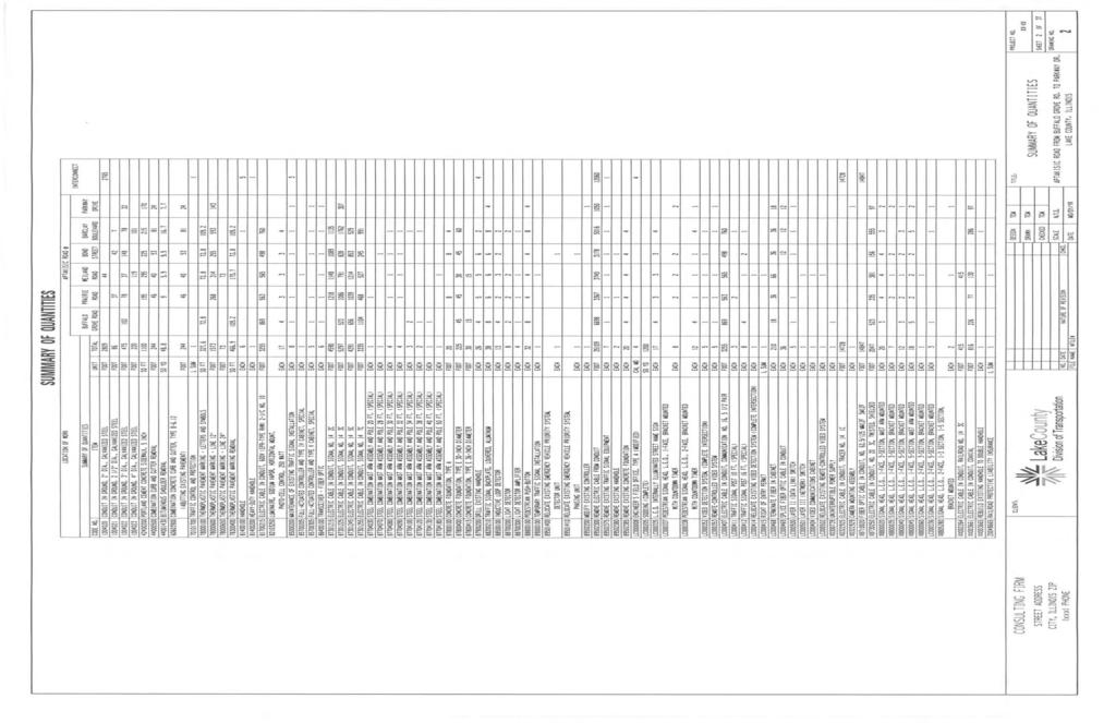
25 Signature block for Engineer s seal. 3. Summary of Quantities A Summary of Quantities is required for all improvement projects, and shall include: The Summary of Quantities sheet shall list items in pay item Code Number sequence, with the full pay code item description. Each item shall be broken into sub-quantities per location and function. The amount of sub-quantity to be paid for by each participating Agency shall be listed. The total quantity shall match the balance of the sub-quantities. The body of the quantities should be in capital letters and include: CODE NUMBER, UNIT, ITEM, and QUANTITY. Items shall be in exactly the same Code Number order as on the Estimate of Cost pages or schedule. 4. Temporary Traffic Signal Plan When temporary traffic signals are required, the Temporary Traffic Signal Plan shall include: North arrow and scale of 1 = 20. Notes for Temporary Traffic Signals. Temporary Traffic Signal Legend. Existing Equipment to be Removed Legend. Remove Existing Traffic Signal Equipment Notes. Existing and proposed geometrics. Existing traffic signal equipment. Temporary traffic signal equipment. Traffic Signal Equipment Data. Dimensioned pole locations. Pole guy wire locations. Lane width dimensions and ROW dimensioned from centerline of roadway. Construction Notes (if necessary). 5. Temporary Cable Plan When temporary traffic signals are required, the Temporary Cable Plan shall include: North arrow. Temporary Cable Plan. Temporary Phase Designation Diagram. Temporary Emergency Vehicle Preemption Sequence. Temporary Cable Plan Legend. Wattage Calculation Table. 6. Traffic Signal Installation or Modification Plan The Traffic Signal Installation or Modification Plan shall include: 20
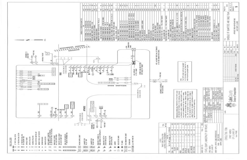
26 North arrow and scale of 1 = 20. Proposed geometrics. Proposed and existing (if applicable) traffic signal equipment and callouts. Construction Notes (if necessary). Traffic Signal Legend. Remove Existing Traffic Signal Equipment Notes (if no temporary traffic signal plans). Traffic Signal Equipment Data. Lane width dimensions and ROW dimensioned from centerline. Pedestrian sign types and locations. 7. Cable Plan, Schedule of Quantities & Phase Designation Diagram The Cable Plan shall include: North arrow. Cable Plan. Phase Designation Diagram. Emergency Vehicle Preemption Sequence. Cable Plan Legend. Wattage Calculation Table. Schedule of Intersection Quantities. 8. Interconnect Plan The Interconnect Plan shall include: North arrow and scale of 1 =50. Proposed geometrics. Proposed and existing (if applicable) traffic signal equipment and callouts. Construction Notes (if necessary). Interconnect Plan Legend. Traffic Signal Equipment Data. ROW dimensioned from centerline. 9. Interconnect Schematic and Schedule of Quantities The Interconnect Schematic shall include: North arrow. Interconnect Schematic Legend. Schedule of Interconnect Quantities. Construction Notes (if necessary). 10. Other Sheets Mast Arm Mounted Street Name Signs Shall be included on every project that involves new mast arms. 21
27 Video Transmission System Schematic Shall be included on every project that involves proposed or existing video detection. LCDOT Standard Traffic Signal Design Details Shall be included on every project. Typical Pavement Markings for County Highways Sheets Shall be included on every project that involves proposed pavement markings. District One Standard Signal Design Details Shall be included on every project. 11. Specifications and Traffic Control and Protection The most recent version of the LCDOT Traffic Signal Specifications, including Traffic Control and Protection, shall be included with every submittal. Any additions to the Specifications must be approved by the County Traffic Engineer before approval of the plans is given. 12. Estimate of Cost An Engineer s Estimate of Cost shall be included with every submittal. The Estimate should be printed on 8 ½ x 11 sized paper. Estimate should include Coded Pay Item Number, Item Description, Unit Price and Total Price for each pay item shown on the Summary of Quantities. The total cost of the project should be shown at the end of the Estimate. Final Estimate should be signed and sealed by the Consulting Engineer. See Appendix C for example. 22
28 APPENDIX A LEGENDS
29
30
31
32
33
34
35
36
37
38
39 APPENDIX B INTERSECTION DESIGN EXAMPLES
40
41
42
43
44
45
46
47
48
49
50
51 APPENDIX C SAMPLE ESTIMATE OF COST, SIGNAL PLANS AND DETAIL SHEETS
52 ENGINEER'S OPINION OF PROBABLE CONSTRUCTION COST CONSULTING FIRM NAME ADDRESS APTAKISIC ROAD TRAFFIC SIGNAL IMPROVEMENTS CITY, IL ZIP LAKE COUNTY, ILLINOIS SHEET 1 OF 2 UNIT CODE NO. ITEM UNIT QTY PRICE TOTAL CONDUIT IN GROUND, 2" DIA., GALVANIZED STEEL FOOT 2809 $10.00 $28, CONDUIT IN GROUND, 2 1/2" DIA., GALVANIZED STEEL FOOT 86 $12.00 $1, CONDUIT IN GROUND, 3" DIA., GALVANIZED STEEL FOOT 475 $16.00 $7, CONDUIT IN GROUND, 4" DIA., GALVANIZED STEEL FOOT 220 $21.00 $4, PORTLAND CEMENT CONCRETE SIDEWALK, 5 INCH SQ FT 1100 $3.25 $3, COMBINATION CURB AND GUTTER REMOVAL FOOT 244 $3.80 $ BITUMINOUS SHOULDER REMOVAL SQ YD 48.8 $20.00 $ COMBINATION CONCRETE CURB AND GUTTER, TYPE B-6.12 (ABUTTING EXISTING PAVEMENT) FOOT 244 $10.00 $2, TRAFFIC CONTROL AND PROTECTION L SUM 1 $51, $51, THERMOPLASTIC PAVEMENT MARKING - LETTERS AND SYMBOLS SQ FT $2.50 $ THERMOPLASTIC PAVEMENT MARKING - LINE 12" FOOT 1573 $1.30 $2, THERMOPLASTIC PAVEMENT MARKING - LINE 24" FOOT 73 $2.75 $ THERMOPLASTIC PAVEMENT MARKING REMOVAL SQ FT $2.00 $ HANDHOLE EACH 6 $1, $6, HEAVY-DUTY HANDHOLE EACH 1 $1, $1, ELECTRIC CABLE IN CONDUIT, 600V (EPR-TYPE RHW) 2-1/C NO. 10 FOOT 3255 $2.00 $6, LUMINAIRE, SODIUM VAPOR, HORIZONTAL MOUNT, PHOTO-CELL CONTROL, 250 WATT EACH 17 $ $6, MAINTENANCE OF EXISTING TRAFFIC SIGNAL INSTALLATION EACH 8 $ $6, FULL-ACTUATED CONTROLLER AND TYPE IV CABINET, SPECIAL EACH 1 $11, $11, FULL-ACTUATED CONTROLLER AND TYPE V CABINET, SPECIAL EACH 5 $12, $62, TRANSCEIVER - FIBER OPTIC EACH 6 $1, $11, ELECTRIC CABLE IN CONDUIT, SIGNAL NO. 14 2C FOOT 4590 $0.80 $3, ELECTRIC CABLE IN CONDUIT, SIGNAL NO. 14 3C FOOT 5297 $0.95 $5, ELECTRIC CABLE IN CONDUIT, SIGNAL NO. 14 5C FOOT 4291 $1.05 $4, ELECTRIC CABLE IN CONDUIT, SIGNAL NO. 14 7C FOOT 3335 $1.10 $3, STEEL COMBINATION MAST ARM ASSEMBLY AND POLE 20 FT. (SPL) EACH 1 $13, $13, STEEL COMBINATION MAST ARM ASSEMBLY AND POLE 28 FT. (SPL) EACH 1 $13, $13, STEEL COMBINATION MAST ARM ASSEMBLY AND POLE 30 FT. (SPL) EACH 4 $13, $55, STEEL COMBINATION MAST ARM ASSEMBLY AND POLE 32 FT. (SPL) EACH 4 $13, $55, STEEL COMBINATION MAST ARM ASSEMBLY AND POLE 34 FT. (SPL) EACH 3 $13, $41, STEEL COMBINATION MAST ARM ASSEMBLY AND POLE 38 FT. (SPL) EACH 2 $14, $28, STEEL COMBINATION MAST ARM ASSEMBLY AND POLE 40 FT. (SPL) EACH 1 $14, $14, STEEL COMBINATION MAST ARM ASSEMBLY AND POLE 50 FT. (SPL) EACH 1 $14, $14, CONCRETE FOUNDATION, TYPE A FOOT 20 $ $2, CONCRETE FOUNDATION, TYPE E 30-INCH DIAMETER FOOT 225 $ $29, CONCRETE FOUNDATION, TYPE E 36-INCH DIAMETER FOOT 30 $ $4, DRILL EXISTING HANDHOLE EACH 26 $ $4, TRAFFIC SIGNAL BACKPLATE, LOUVERED, ALUMINUM EACH 38 $ $4, INDUCTIVE LOOP DETECTOR EACH 13 $ $1, Design Engineer APPROVED LAKE COUNTY DIVISION OF TRANSPORTATION DATE 20 COUNTY ENGINEER CONTINUED ON NEXT PAGE
53 APTAKISIC ROAD TRAFFIC SIGNAL IMPROVEMENTS LAKE COUNTY, ILLINOIS SHEET 2 OF 2 UNIT CODE NO. ITEM UNIT QTY PRICE TOTAL LIGHT DETECTOR EACH 8 $ $6, LIGHT DETECTOR AMPLIFIER EACH 4 $1, $6, PEDESTRIAN PUSH-BUTTON EACH 32 $ $5, TEMPORARY TRAFFIC SIGNAL INSTALLATION EACH 1 $35, $35, RELOCATE EXISTING EMERGENCY VEHICLE PRIORITY SYSTEM, DETECTOR UNIT EACH 1 $ $ RELOCATE EXISTING EMERGENCY VEHICLE PRIORITY SYSTEM, PHASING UNIT EACH 1 $1, $1, MODIFY EXISTING CONTROLLER EACH 1 $2, $2, REMOVE ELECTRIC CABLE FROM CONDUIT FOOT $0.50 $17, REMOVE EXISTING TRAFFIC SIGNAL EQUIPMENT EACH 7 $1, $8, REMOVE EXISTING HANDHOLE EACH 2 $ $ REMOVE EXISTING CONCRETE FOUNDATION EACH 20 $ $5, LC ENGINEER'S FIELD OFFICE, TYPE A (MODIFIED) CAL MO 4 $1, $6, LC SODDING (COMPLETE) SQ YD 1200 $30.00 $36, LC PEDESTRIAN SIGNAL HEAD, L.E.D., 1-FACE, BRACKET MOUNTED WITH COUNTDOWN TIMER EACH 8 $1, $10, LC PEDESTRIAN SIGNAL HEAD, L.E.D., 2-FACE, BRACKET MOUNTED WITH COUNTDOWN TIMER EACH 12 $1, $22, LC L.E.D. INTERNALLY ILLUMINATED STREET NAME SIGN EACH 17 $2, $34, LC VIDEO DETECTION SYSTEM, (COMPLETE INTERSECTION) EACH 5 $33, $165, LC REMOTE-CONTROLLED VIDEO SYSTEM EACH 5 $2, $13, LC ELECTRIC CABLE IN CONDUIT, COMMUNICATION NO. 16, 5 1/2 PAIR FOOT 3255 $1.50 $4, LC TRAFFIC SIGNAL POST 10 FT. (SPECIAL) EACH 3 $3, $9, LC TRAFFIC SIGNAL POST 16 FT. (SPECIAL) EACH 8 $3, $28, LC RELOCATE EXISTING VIDEO DETECTION SYSTEM (COMPLETE INTERSEC EACH 1 $1, $1, LC RIGHT OF ENTRY PERMIT L SUM 1 $1, $1, LC TERMINATE FIBER IN CABINET EACH 210 $50.00 $10, LC SPLICE FIBER OPTIC CABLE IN CABINET EACH 36 $50.00 $1, LC LAYER II (DATA LINK) SWITCH EACH 5 $5, $27, LC LAYER III (NETWORK) SWITCH EACH 1 $8, $8, LC VIDEO COMMUNICATIONS CABINET EACH 1 $21, $21, LC RELOCATE EXISTING REMOTE-CONTROLLED VIDEO SYSTEM EACH 1 $ $ X UNINTERRUPTIBLE POWER SUPPLY EACH 1 $6, $6, X ELECTRIC CABLE IN CONDUIT, TRACER NO. 14 1C FOOT $1.15 $16, X CAMERA MOUNTING ASSEMBLY EACH 1 $1, $1, X FIBER OPTIC CABLE IN CONDUIT, NO. 62.5/125 MM12F SM12F FOOT $3.00 $44, X ELECTRIC CABLE IN CONDUIT, NO. 20 3C, TWISTED, SHIELDED FOOT 2047 $1.25 $2, X SIGNAL HEAD, L.E.D., 1-FACE, 3-SECTION, MAST ARM MOUNTED EACH 20 $ $19, X SIGNAL HEAD, L.E.D., 1-FACE, 3-SECTION, BRACKET MOUNTED EACH 7 $ $6, X SIGNAL HEAD, L.E.D., 1-FACE, 5-SECTION, BRACKET MOUNTED EACH 12 $1, $16, X SIGNAL HEAD, L.E.D., 1-FACE, 5-SECTION, MAST ARM MOUNTED EACH 18 $1, $26, X SIGNAL HEAD, L.E.D., 2-FACE, 3-SECTION, BRACKET MOUNTED EACH 1 $1, $1, LC SIGNAL HEAD, L.E.D., 2-FACE, 5-SECTION, BRACKET MOUNTED EACH 3 $2, $8, X SIGNAL HEAD, L.E.D., 2-FACE, 1-3 SECTION, 1-5 SECTION, BRACKET MOUNTED EACH 2 $2, $5, XX ELECTRIC CABLE IN CONDUIT, RAILROAD NO. 14 3C FOOT 415 $2.15 $ XX ELECTRIC CABLE IN CONDUIT, COAXIAL FOOT 816 $1.60 $1, XX REBUILD EXISTING HANDHOLE TO DOUBLE HANDHOLE EACH 1 $2, $2, Z RAILROAD PROTECTIVE LIABILITY INSURANCE L SUM 1 $7, $7, SUB-TOTAL $1,174, % CONTINGENCY $117, TOTAL $1,291,596.52
54
55
56
57

58
59
60
61
62
63
SECTION 5900 TRAFFIC SIGNALS CITY OF LEE S SUMMIT, MISSOURI DESIGN CRITERIA
 SECTION 5900 TRAFFIC SIGNALS CITY OF LEE S SUMMIT, MISSOURI DESIGN CRITERIA TABLE OF CONTENTS Section Title Page 5901 GENERAL... 2 5902 DESIGN CRITERIA... 2 5902.1 Codes and Standards... 2 5902.2 Signal
Office of Traffic Operations Signal Design Reference Packet
 Office of Traffic Operations Signal Design Reference Packet Rev-2 04/17/2015 Contents The purpose of this packet is to provide guidance on designing and reviewing traffic signal plans. The format, legends,
CHAPTER 14 WIRING SIGNALS AND LIGHTING FIELD GUIDE Wiring Requirements WIRING
 WIRING CHAPTER 14 WIRING The installation of all wiring, including electrical cables and conductors, must conform to the National Electrical Code (NEC). The Code represents the minimum required standard.
CONSTRUCTION SPECIFICATION FOR TRAFFIC SIGNAL EQUIPMENT
 ONTARIO PROVINCIAL STANDARD SPECIFICATION METRIC OPSS.PROV 620 APRIL 2017 CONSTRUCTION SPECIFICATION FOR TRAFFIC SIGNAL EQUIPMENT TABLE OF CONTENTS 620.01 SCOPE 620.02 REFERENCES 620.03 DEFINITIONS 620.04
BILOXI PUBLIC SCHOOL DISTRICT. Biloxi Junior High School
 BILOXI PUBLIC SCHOOL DISTRICT Biloxi Junior High School Request for Proposals E-Rate 2014-2015 - Internal Connections Submit Proposals To: Purchasing Department Attn: Traci Barnett 160 St. Peter Street
Work Type Definition and Submittal Requirements. Work Type Definition: Traffic Signal Design
 The first section, Work Type Definition, provides a detailed explanation of the work type. The second section, Work Type Submittal Requirements, identifies the requirements a firm must meet to become pre-qualified
Public Works Division Lighting District Fiber Optic Specifications April 2009
 Public Works Division Lighting District Fiber Optic Specifications April 2009 7000 Florida Street Punta Gorda, Florida 33950 Tele: 941.575.3600 Fax : 941.637.9265 www.charlottecountyfl.com/publicworks
TEO Signal Committee Meeting Minutes Meeting Date: 05/19/2009 Waters Edge Conference Rm 176 Meeting Time: 9:00am - Noon
 TEO Signal Committee Meeting Minutes Meeting Date: 05/19/2009 Waters Edge Conference Rm 176 Meeting Time: 9:00am - Noon Meeting Attendees: Kile Holm Sue Zarling Curt Krohn Mike Schroeder Tim Bangsund Jeff
IndyGo Facility Upgrades Project 35671EE
 SECTION 260553 IDENTIFICATION FOR ELECTRICAL SYSTEMS PART 1 - GENERAL 1.1 SUMMARY A. Section Includes: 1. Identification for raceways. 2. Identification of power and control cables. 3. Identification for
SECTION MEDIUM VOLTAGE CABLE INSTALLATION. 1. Section Underground Ducts and Manholes.
 SECTION 33 71 49.23 MEDIUM VOLTAGE CABLE INSTALLATION PART 1 GENERAL 1.1 SCOPE A. Work included in this Section: Medium Voltage Cable (4 kv and 12 kv) Installation and Termination. Removal and return of
All Dielectric Self Supporting (ADSS) Fiber Optic Cable Installation
 Fiber Optic Cable Installation") All Dielectric Self Supporting (ADSS) Fiber Optic Cable Installation Underground Installation M P - 1012 Issue #3 March 2011 DISCLAIMER OF WARRANTIES AND LIMITATION OF LIABILITIES The practices contained
All Dielectric Self Supporting (ADSS) Fiber Optic Cable Installation Underground Installation M P - 1012 Issue #3 March 2011 DISCLAIMER OF WARRANTIES AND LIMITATION OF LIABILITIES The practices contained
Special Provision Fiber Optic Cable Section 643. The Contractor shall install fiber optic cable in conduit where shown on the plan sheets.
 Special Provision Fiber Optic Cable Section 643 The Contractor shall install fiber optic cable in conduit where shown on the plan sheets. ATRC Fiber Optic Specifications: To ensure compatibility and proper
Aerial Cable Installation Best Practices
 Aerial Cable Installation Best Practices Panduit Corp. 2007 BEST PRACTICES Table of Contents 1.0 General... 3 2.0 Introduction... 3 3.0 Precautions... 4 4.0 Pre-survey... 5 5.0 Materials and Equipment...
SECTION FIBER OPTIC STATION CABLES
 PART 1 GENERAL 1.01 DESCRIPTION A. The work covered by this section of the Specifications shall include all labor necessary to perform and complete such construction, all materials and equipment incorporated
1.0 DESCRIPTION. This specification covers roll-up signs to be used in temporary traffic control zones.
 (Page 1 of 10) ROLL-UP SIGNS (MGS-04-01O) 1.0 DESCRIPTION. This specification covers roll-up signs to be used in temporary traffic control zones. 2.0 MATERIAL. 2.1 SIGNS AND OVERLAYS. 2.1.1 SUBSTRATES.
U-verse Outside Plant Cabinets AT&T Knowledge Ventures. All rights reserved. AT&T and the AT&T logo are trademarks of AT&T Knowledge Ventures.
 U-verse Outside Plant s U-verse Outside Plant (OSP) Certifications AT&T certifies that Lightspeed cabinets, wiring and equipment have been inspected for and are compliant to the following industry standards:
VISSIM TUTORIALS This document includes tutorials that provide help in using VISSIM to accomplish the six tasks listed in the table below.
 VISSIM TUTORIALS This document includes tutorials that provide help in using VISSIM to accomplish the six tasks listed in the table below. Number Title Page Number 1 Adding actuated signal control to an
STATE OF OHIO DEPARTMENT OF TRANSPORTATION SUPPLEMENTAL SPECIFICATION 872 LIGHT EMITTING DIODE TRAFFIC SIGNAL LAMP UNITS JULY 19, 2002
 STATE OF OHIO DEPARTMENT OF TRANSPORTATION SUPPLEMENTAL SPECIFICATION 872 LIGHT EMITTING DIODE TRAFFIC SIGNAL LAMP UNITS JULY 19, 02 872.01 Description 872.02 Prequalification 872.03 Material Requirements
SECTION FIVE COBB COUNTY TRAFFIC SIGNAL SPECIFICATIONS
 SECTION FIVE COBB COUNTY TRAFFIC SIGNAL SPECIFICATIONS COBB COUNTY DOT TRAFFIC SIGNAL SPECIFICATIONS OCTOBER 2017 Table of Contents Section 647 Traffic Signal Installation 4 Section 687 Signal Timing 35
September 28, 2018 CITY OF BERKELEY JOHN MUIR SCHOOL CROSSING IMPROVEMENTS SPECIFICATION NO C ADDENDUM NO. 2
 Department of Public Works Transportation Division September 28, 2018 CITY OF BERKELEY JOHN MUIR SCHOOL CROSSING IMPROVEMENTS ADDENDUM NO. 2 Dear Bidder: The following amendments are hereby made to the
400 TRAFFIC SIGNALS Traffic Engineering Manual
 TABLE OF CONTENTS Part 4 - SIGNALS 400 GENERAL... 4-9 400-1 Introduction... 4-9 400-2 Construction Projects... 4-9 400-3 Force Account (ODOT Operations) Work... 4-9 401 TRAFFIC CONTROL SIGNALS - GENERAL...
STRUCTURED CABLE SYSTEM (SCS)
") PART 1 GENERAL 1.01 DESCRIPTION A. The work covered by this section of the Specifications includes all labor necessary to perform and complete such construction, all materials and equipment incorporated
PART 1 GENERAL 1.01 DESCRIPTION A. The work covered by this section of the Specifications includes all labor necessary to perform and complete such construction, all materials and equipment incorporated
California Polytechnic State University ITS Telecommunications PART 1 GENERAL SECTION AUDIO VISUAL STATION CABLES 1.
 PART 1 GENERAL 1.01 DESCRIPTION A. The work covered by this section of the Specifications includes all labor necessary to perform and complete such construction, all materials and equipment incorporated
MILITARY SPECIFICATION SHEET
 INCH POUND MIL-S-22885/100A 16 May 2003 SUPERSEDING MIL-S-22885/100 (USAF) 27 August 1982 MILITARY SPECIFICATION SHEET SWITCH, PUSH BUTTON, ILLUMINATED, 4-LAMP, SPDT AND DPDT, 7.5 AMPERES, SILVER CONTACTS,
Coastal Carolina University RE-BID WILLIAMS BRICE RENOVATION AND REPAIR October 19, 2018 Construction Documents
 PART 1 - GENERAL 1.1 SUMMARY SECTION 271500 COMMUNICATIONS HORIZONTAL CABLING A. Section Includes: 1. UTP cabling. 2. Telecommunications outlet/connectors. 3. Cabling system identification products. 1.2
Village of Glenview Appearance Commission
 Village of Glenview Appearance Commission STAFF REPORT February 6, 2013 TO: Chairman and Appearance Commissioners FROM: Planning & Economic Development Department CASE MANAGER: Michelle House, Planner
Special Specification 6293 Adaptive Traffic Signal Control System
 Special Specification Adaptive Traffic Signal Control System 1. DESCRIPTION 2. MATERIALS Furnish, install, relocate, or remove adaptive traffic signal control (ATSC) system software and equipment at locations
Minimum qualifications for the Telecommunications Engineer are: A. Texas Licensed Profession Engineer (PE)
") PART 1: GENERAL 1.01 Telecommunications Engineer Minimum qualifications for the Telecommunications Engineer are: A. Texas Licensed Profession Engineer (PE) B. Registered Communications Distribution Designer
PART 1: GENERAL 1.01 Telecommunications Engineer Minimum qualifications for the Telecommunications Engineer are: A. Texas Licensed Profession Engineer (PE) B. Registered Communications Distribution Designer
TruePlate Structural Plate
 TruePlate Structural Plate Galvanized Steel and Aluminum Alloy Sizes, Shapes and Height of Cover Tables TrueNorthSteel.com info@truenorthsteel.com 866-82-511 TruePlate Structural Plate Many drainage and
ACADEMIC SUCCESS CENTER THE COLLEGE AT BROCKPORT STATE UNIVERSITY OF NEW YORK PROJECT NO
 SECTION 270536 - CABLE TRAYS FOR COMMUNICATIONS SYSTEMS PART 1 - GENERAL 1.1 RELATED DOCUMENTS A. Drawings and general provisions of the Contract, including General and Supplementary Conditions and Division
SPECIAL SPECIFICATION 8540 Telecommunication Cable
 2004 Specifications CSJ 0914-00-307 & CSJ 0914-25-003 SPECIAL SPECIFICATION 8540 Telecommunication Cable 1. Description. This specification governs the materials, installation, termination, splicing, testing,
1. The contractor shall ensure that: c) Contractor or sub-contractor has at least 5 years experience
 Contractor or sub-contractor has at least 5 years experience") Black text from standard FAA spec Strikeout text deletions from FAA standard spec Blue text additions to FAA standard spec Red text notes to the Engineer/won t appear in spec I. DESCRIPTION A. GENERAL
Black text from standard FAA spec Strikeout text deletions from FAA standard spec Blue text additions to FAA standard spec Red text notes to the Engineer/won t appear in spec I. DESCRIPTION A. GENERAL
REPORT TO THE PLANNING COMMISSION
 REPORT TO THE PLANNING COMMISSION Meeting Date: May 13, 2015 Application: Design Review PDR15-0006 Location / APN: Near 19700 Prospect Road / 386-35-070 Owner / Applicant: Staff Planner: City of Saratoga
SECTION COMMUNICATIONS HORIZONTAL CABLING
 SECTION 271500 COMMUNICATIONS HORIZONTAL CABLING PART 1 - GENERAL 1.1 SUMMARY A. Section Includes: 1. UTP cabling. 2. Telecommunications outlet/connectors including patch panels. 3. Cabling identification
Michigan State University Construction Standards EXTERIOR FIBER OPTIC CABLE SYSTEM PAGE
 PAGE 271800-1 SECTION 271800 PART 1 - GENERAL 1.1 RELATED DOCUMENTS A. Drawings and general provisions of the Contract, including General and Supplementary Conditions and Division 01 Specification Sections,
SECTION 7 -- CROSS-CONNECT SYSTEMS
 DETAIL ENGINEERING REQUIREMENTS AT&T March, 2016 Section 7, ATT-TP-76400 Revised NA SECTION 7 -- CROSS-CONNECT SYSTEMS CONTENTS PAGE 1. GENERAL... 7-2 1.1. Introduction... 7-2 1.2. Cable Holes... 7-2 1.3.
UNIFIED FACILITIES GUIDE SPECIFICATIONS
 USACE / NAVFAC / AFCEC / NASA UFGS-27 05 14.00 10 (April 2006) -------------------------------- Preparing Activity: USACE Superseding UFGS-27 05 14.00 10 (April 2004) UNIFIED FACILITIES GUIDE SPECIFICATIONS
SPECIAL SPECIFICATION 6559 Telecommunication Cable
 2004 Specifications CSJ 0015-09-147, etc. SPECIAL SPECIFICATION 6559 Telecommunication Cable 1. Description. This specification governs the materials, installation, termination, splicing, testing, training,
Azatrax Model Railroad Track Signal Control - Single Track
 Installation Guide Azatrax Model Railroad Track Signal Control - Single Track TS2 What it is: The TS2 operates one or two trackside block signals (one in each direction) on one track to simulate the block
Old Business. TEO Signal Committee Meeting Minutes Waters Edge Conf. Room C September 16, 2004
 Attendees: Jerry Kotzenmacher Ray Star Mike Wolf Marlin Reinardy Kevin Schwartz Greg Gruber Roger Sowder Mike Gerbenski Jim Deans Tom Dumont Kile Holm Ben Osemenam Old Business TEO Signal Committee Meeting
Primex Wireless, Inc. July, Wells Street Lake Geneva, WI
 Division 0 0 0 0 Primex Wireless, Inc. July, 00 Wells Street Lake Geneva, WI 00--0 www.primexwireless.com Product Guide Specification Specifier Note: This product specification is written according to
GS122-2L. About the speakers:
 Dan Leighton DL Consulting Andrea Bell GS122-2L A growing number of utilities are adapting Autodesk Utility Design (AUD) as their primary design tool for electrical utilities. You will learn the basics
RENEWAL OF PREVIOUSLY APPROVED OUTDOOR MARKETING GRAPHIC DISPLAY PERMIT FEE: $25.00
 Borough of Haddonfield Outdoor Marketing Graphic Display Permit PLEASE COMPLETE ENTIRE PACKET Insurance form is required for all permit applications! An application is required PRIOR to displaying an Outdoor
SPECIAL SPECIFICATION 6911 Fiber Optic Video Data Transmission Equipment
 2004 Specifications CSJ 3256-02-079 & 3256-03-082 SPECIAL SPECIFICATION 6911 Fiber Optic Video Data Transmission Equipment 1. Description. Furnish and install Fiber Optic Video Data Transmission Equipment
Identification - electrical services
 Identification - electrical services Aesthetic All live phase cable sheathing to be brown coloured and neutral phase cable sheathing to be blue coloured, all labelled L1, L2, L3 & N respectively in accordance
SITE All work shall be performed at Center Park Substation (1895 Kernan Blvd, Jacksonville, Fl ). DATE: 04/03/2018
. DATE: 04/03/2018") DATE: 04/03/2018 TO: The Contractor FROM: System Protection & Control Projects 20413 SUBJECT: Technical Specifications for Center Park APSTF Project PROJECT OVERVIEW This is a general specification that
DATE: 04/03/2018 TO: The Contractor FROM: System Protection & Control Projects 20413 SUBJECT: Technical Specifications for Center Park APSTF Project PROJECT OVERVIEW This is a general specification that
A449-6S 70 CENTIMETER FM YAGI ANTENNA MHz
 ASSEMBLY AND INSTALLATION A449-6S 70 CENTIMETER FM YAGI ANTENNA 440-450 MHz COMMUNICATIONS ANTENNAS 951425 (7/93) WARNING THIS ANTENNA IS AN ELECTRICAL CONDUCTOR. CONTACT WITH POWER LINES CAN RESULT IN
Sign Program for Temporary Real Estate Signs Revision #2
 Pacifica San Juan Sign Program for Temporary Real Estate Signs Revision # Prepared For: City of San Juan Capistrano Prepared By: Pacific Point Development Partners LCC January 017 Introduction In August
VISSIM Tutorial. Starting VISSIM and Opening a File CE 474 8/31/06
 VISSIM Tutorial Starting VISSIM and Opening a File Click on the Windows START button, go to the All Programs menu and find the PTV_Vision directory. Start VISSIM by selecting the executable file. The following
In the proposed amendment below, text shown with underline is proposed to be added and text shown with strikethrough is proposed to be removed.
 ZOA-13-07 AN ORDINANCE TO AMEND, REENACT AND RECODIFY ARTICLES 13 AND 18 OF THE ARLINGTON COUNTY ZONING ORDINANCE TO DEFINE LARGE MEDIA SCREENS AS AUTOMATIC CHANGEABLE COPY SIGNS LARGER THAN 12 SQUARE
Mediacom Upgrade/Splicing Procedures (based on original document from Corporate dated 4/16/98)
") Mediacom Upgrade/Splicing Procedures (based on original document from Corporate dated 4/16/98) 1. Splicing specifications are provided by Mediacom, but due to resplice conditions, many locations become
Mediacom Upgrade/Splicing Procedures (based on original document from Corporate dated 4/16/98) 1. Splicing specifications are provided by Mediacom, but due to resplice conditions, many locations become
Colour Explosion Proof Video Camera USER MANUAL VID-C
 Colour Explosion Proof Video Camera USER MANUAL VID-C Part Number: MAN-0036-00 Rev 4 Copyright 2002 Net Safety Monitoring Inc. Printed in Canada This manual is provided for informational purposes only.
Special Specification 6002 Video Imaging Vehicle Detection System
 6002 Special Specification 6002 Video Imaging Vehicle Detection System 1. DESCRIPTION 2. DEFINITIONS Install a Video Imaging Vehicle Detection System (VIVDS) that monitors vehicles on a roadway via processing
Bravo AV s Structured or Whole-House Wiring Approach
 Custom Audio & Video Systems: Design and Installation Bravo AV s Structured or Whole-House Wiring Approach THE QUALITY OF THE CABLE YOU USE IS CRITICALLY IMPORT TO THE PERFORMANCE OF YOUR SYSTEM Introduction
EXHIBIT BASIS OF DESIGN REPORT. Space Type: Space Usage: Off-center of room to match side screen. Location
 AV Basis of Design Illinois Project #: Space Location: Date of Creation: Latest Revision: General Information Space Type: Space Usage: Other Notes: Project Name: Room Types Presentation Room Room Numbers
SECTION 686 VIDEO DECODER DESCRIPTION
 686 SECTION 686 VIDEO DECODER DESCRIPTION 686.01.01 GENERAL A. This specification describes the functional, performance, environmental, submittal, documentation, and warranty requirements, as well as the
SPECIAL SPECIFICATION 1291 Fiber Optic Video Data Transmission Equipment
 1993 Specifications CSJ 0500-01-117 SPECIAL SPECIFICATION 1291 Fiber Optic Video Data Transmission Equipment 1. Description. This Item shall govern for the furnishing and installation of Fiber Optic Video
Axle Assembly Poke-Yoke
 Indiana University Purdue University Fort Wayne Opus: Research & Creativity at IPFW Manufacturing & Construction Engineering Technology and Interior Design Senior Design Projects School of Engineering,
University Center AV Integration Construction Documents February 8, 2012
 SECTION 27 41 30 AUDIOVISUAL ARCHITECTURAL SPACES PART 1 GENERAL 1.01 SUMMARY A. This Section defines the Audiovisual System requirements for Audiovisual Systems within Architectural Spaces. 1.02 RELATED
EVALUATION OF PERFORMANCE OF SOLAR POWERED FLASHING BEACONS AT ROOM TEMPERATURE CONDITIONS
 CIVIL ENGINEERING STUDIES Illinois Center for Transportation Series No. 10-069 UILU-ENG-2010-2010 ISSN: 0197-9191 EVALUATION OF PERFORMANCE OF SOLAR POWERED FLASHING BEACONS AT ROOM TEMPERATURE CONDITIONS
NORTHWESTERN UNIVERSITY PROJECT NAME JOB # ISSUED: 03/29/2017
 SECTION 26 0553 - IDENTIFICATION FOR ELECTRICAL SYSTEMS PART 1 - GENERAL 1.1 RELATED DOCUMENTS A. Drawings and general provisions of the Contract, including General and Supplementary Conditions and Division
Preparing a home for TransACT fibre-to-the-premise (FTTP) services
 services") Preparing a home for TransACT fibre-to-the-premise (FTTP) services A guide for builders, telecommunications cablers and home owners transact.com.au For more information call TransACT s FTTP Sales Manager,
Preparing a home for TransACT fibre-to-the-premise (FTTP) services A guide for builders, telecommunications cablers and home owners transact.com.au For more information call TransACT s FTTP Sales Manager,
Lineside Signals, Indicators and Layout of Signals
 Lineside Signals, Indicators and Layout of Signals Synopsis This document defines the format, presentation and layout of lineside signalling equipment that is used to display movement authority information
Structural Plate Design Guide. 5 th Edition MULTI-PLATE. Aluminum Structural Plate. Aluminum Box Culvert SUPER-SPAN SUPER-PLATE.
 ENGINEERED SOLUTIONS Structural Plate Design Guide 5 th Edition MULTI-PLATE Aluminum Structural Plate SUPER-SPAN SUPER-PLATE BridgeCor Table of Contents Steel and Aluminum Structural Plate design guide.
Site Installation Model MP-8433
 Site Installation Model MP- Rev. //0 SCOREBOARD SITE INSTALLATION INSTRUCTIONS CAUTION: All American Scoreboards (AAS) recommends the sign be installed by a licensed contractor, and must meet all local
Follow The Leader In Shielded Technology
 1970s Vampire Tap 1990s Shielded Modular Jack 190s 4 Position Data Connector Follow The Leader In Shielded Technology The new AMP-TWIST Jack is our latest shielded product evolution. It can be terminated
SPECIAL SPECIFICATION 6740 Video Imaging Vehicle Detection System
 1995 Metric CSJ s 0918-45-344 & 0008-08-059 SPECIAL SPECIFICATION 6740 Video Imaging Vehicle Detection System 1. Description. Install a Video Imaging Vehicle Detection System (VIVDS) that monitors vehicles
Roadway/Structure Widening Project MP A30.30 to MP A Lansdale Montgomery County, PA NOISE ANALYSIS REPORT FINAL. August 2006.
 Roadway/Structure Widening Project Lansdale Montgomery County, PA NOISE ANALYSIS REPORT Prepared for: Pennsylvania Turnpike Commission P.O. Box 67676 Harrisburg, PA 17106-7676 August 2006 FINAL EXECUTIVE
Tab 10 - The NESC and Underground Applications. Restricted Siemens Industry, Inc All rights reserved.
 Tab 10 - The NESC and Underground Applications Restricted Siemens Industry, Inc. 2017 All rights reserved. siemens.com/poweracademy The National Electric Safety Code (NESC) The NESC provides guidelines
SPECIAL SPECIFICATION 2344 TMC Support Equipment
 2004 Specifications CSJ 0912-00-488 SPECIAL SPECIFICATION 2344 TMC Support Equipment 1. Description. Furnish Traffic Management Center (TMC) support equipment in the City of Missouri City TMC location
Implementation of LED Roadway Lighting
 Implementation of LED Roadway Lighting Ken Taillon, Principal Investigator Short Elliot Hendrickson, Inc. (SEH ) May 2016 Research Project Final Report 2016-17 To request this document in an alternative
SPECIAL SPECIFICATION 6735 Video Optical Transceiver
 2004 Specifications CSJ 0924-06-244 SPECIAL SPECIFICATION 6735 Video Optical Transceiver 1. Description. This Item governs the furnishing and installation of Video optical transceiver (VOTR) in field location(s)
Request for Proposals Fiber Optic Network Backbone Upgrades
 Introduction Request for Proposals Fiber Optic Network Backbone Upgrades RFP Released on February 18, 2015 The Dexter R-11 Public School District is seeking proposals from qualified service providers to
DESIGN STANDARD FOR AUDIOVISUAL SYSTEMS
 DESIGN STANDARD FOR AUDIOVISUAL SYSTEMS General: The SCC is intent on moving to 21 st century unified communications and data systems, consistent with industry standards and best practices as they evolve.
EXHIBIT BASIS OF DESIGN REPORT. Space Type: Space Usage: Approx. 2,000 BTU each. Off-center of room to match side screen.
 AV Basis of Design Illinois Project #: Space : Date of Creation: Latest Revision: General Information Space : Space Usage: Other Notes: Project Name: Room s Presentation Room Room Numbers 1 System AV Presentation
BRIGHT BRIGHTER BRIGHTEST ONE ILLUMINATOR DESIGN THREE LIGHT SOURCES. featuring the EvenVue Reflector System
 BRIGHT BRIGHTER BRIGHTEST ONE ILLUMINATOR DESIGN THREE LIGHT SOURCES featuring the EvenVue Reflector System DVC (DIAGNOSTIC VIEWING CENTER) The features and benefits of the TECHLINE can be combined with
UNIVERSITY of NORTH DAKOTA LOW VOLTAGE COMMUNICATIONS STANDARDS FOR CABLING, PATHWAYS, AND SPACE
 UNIVERSITY of NORTH DAKOTA LOW VOLTAGE COMMUNICATIONS STANDARDS FOR CABLING, PATHWAYS, AND SPACE Prepared in cooperation and approval from BICSI Building Industry Consulting Services International and
Site Installation Model MP-8424
 Site Installation Model MP- Rev. //0 SCOREBOARD SITE INSTALLATION INSTRUCTIONS CAUTION: All American Scoreboards (AAS) recommends the sign be installed by a licensed contractor, and must meet all local
Pre-bid Supplement #01 Communications Specifications and Additional Scope Project Bid: CM Date: 05/26/2017
 Pre-bid Supplement #01 Communications Specifications and Additional Scope Project Bid: CM-2017-2 Date: 05/26/2017 Additional specification information for data communication to cameras and between Library
MILWAUKEE AVENUE CORRIDOR COMMITTEE FEBRUARY 12, 2015 MEETING SUMMARY
 MILWAUKEE AVENUE CORRIDOR COMMITTEE FEBRUARY 12, 2015 MEETING SUMMARY CALL TO ORDER The meeting was called to order by Co Chair Jekot at 8:00 a.m. ATTENDANCE The following Committee members were in attendance:
SECTION TESTING, IDENTIFICATION AND ADMINISTRATION
 PART 1 - GENERAL 1.1 SUMMARY SCOPE SECTION 25170 TESTING, IDENTIFICATION AND ADMINISTRATION 1. This section includes the minimum requirements for the testing, certification administration and identification
MPCE Monitoring, Machine Test Signal. Guard Mode, Remote Reset. Eact Channel Select and Floating Blanking. Adjustable mounting brackets
 MicroSafe MCF4700 C US File No. LR90200 MicroSafe Flexible MCF4700-12, MCF4700-20, MCF4700-30 12 mm, 20 mm and 30 mm resolution versions Compact segmented light curtain 1.02 inch (26 mm) x 1.1 inch (28
United States Patent (19) Gartner et al.
 Gartner et al.") United States Patent (19) Gartner et al. 54) LED TRAFFIC LIGHT AND METHOD MANUFACTURE AND USE THEREOF 76 Inventors: William J. Gartner, 6342 E. Alta Hacienda Dr., Scottsdale, Ariz. 851; Christopher R.
United States Patent (19) Gartner et al. 54) LED TRAFFIC LIGHT AND METHOD MANUFACTURE AND USE THEREOF 76 Inventors: William J. Gartner, 6342 E. Alta Hacienda Dr., Scottsdale, Ariz. 851; Christopher R.
THE CITY OF WINNIPEG BY-LAW NO. 36/2013
 THE CITY OF WINNIPEG BY-LAW NO. 36/2013 A By-law of The City of Winnipeg to amend Winnipeg Zoning By-law No. 200/2006 with respect to digital signs and billboards. THE CITY OF WINNIPEG, in Council assembled,
Room Recommendations for the Cisco TelePresence System 3210
 CHAPTER 2 Room Recommendations for the Cisco TelePresence System 3210 Revised: February 20, 2012, This chapter provides you with general room recommendations for the Cisco TelePresence System 3210 (CTS
Illustrated Feature. Options
 Applications Enclosed and gasketed fixtures for use where vapors, moisture, dirt or corrosive atmospheres are encountered. For use in hazardous locations defined by the NEC as Class I, Division 2. Groups
A CENTIMETER FM YAGI ANTENNA MHz
 ASSEMBLY AND INSTALLATION A449-70 CENTIMETER FM YAGI ANTENNA 440-450 MHz COMMUNICATIONS ANTENNAS 951424 (10/91) WARNING THIS ANTENNA IS AN ELECTRICAL CONDUCTOR. CONTACT WITH POWER LINES CAN RESULT IN DEATH
DESIGN STANDARD FOR AUDIOVISUAL SYSTEMS
 DESIGN STANDARD FOR AUDIOVISUAL SYSTEMS General: Solano Community College (SCC) is intent on moving to 21 st century unified communications and data systems, consistent with industry standards and best
TITLE: FIBER OPTIC SHOCK FIXTURES
 ENGINEERING PRACTICE STUDY TITLE: FIBER OPTIC SHOCK FIXTURES 18 January 2007 STUDY PROJECT 60GP-2006-019 FINAL REPORT Study Conducted By Dave Leight DSCC-VAT Fiber Optic Group Prepared by: Dave Leight
Request for Quote E- Rate Eligible Services Scope of Work - Wireless LAN and Cabling for Access Points
 Request for Quote E- Rate Eligible Services Scope of Work - Wireless LAN and Cabling for Access Points Due Date: Allowable Contract Date from Posted 470 The Palo Verde Elementary School District is requesting
APPENDIX D TECHNOLOGY. This Appendix describes the technologies included in the assessment
 APPENDIX D TECHNOLOGY This Appendix describes the technologies included in the assessment and comments upon some of the economic factors governing their use. The technologies described are: coaxial cable
Lineside Signals, Indicators and Layout of Signals
 To be part superseded by GKRT0045 Iss 4, GKRT0057 Iss 1 and GKRT0058 Iss 1 published on 06/12/2014 Lineside Signals, Indicators and Layout of Signals Synopsis This document defines the format, presentation
Section Communications Optical Fiber Backbone Cabling
 Part 1 1.1 Related Documents 1.1.1 Drawings and general provisions of the Contract, including General and Supplementary Conditions and Division 01 Specifications Sections apply to this Section. 1.2 Related
A. Section Includes: Division 1 applies to this section. Provide GPS wireless clock system, complete.
 SPECIFICATIONS GPS Wireless Clock System Section 16730 TIME SYSTEM PART 1 - GENERAL 1.01 SUMMARY A. Section Includes: Division 1 applies to this section. Provide GPS wireless clock system, complete. B.
TEST REPORT CHOMERICS R&D. PREMIER EMI Shielding Thermoplastic Face Plate Shielding Effectiveness 84 DRAGON COURT WOBURN, MA 01801
 TEST REPORT CHOMERICS PREMIER EMI Shielding Thermoplastic Face Plate Shielding Effectiveness Prepared by: CHOMERICS R&D 84 DRAGON COURT WOBURN, MA 01801 Date: May 2006 Test Report Number: TR 1011 EN05/06
DLP ANTENNA INSTRUCTION MANUAL. Dielectric LLC 22 Tower Road Raymond, Maine Phone:
 DLP ANTENNA INSTRUCTION MANUAL Dielectric LLC 22 Tower Road Raymond, Maine 04071 Phone: 800-341-9678 TABLE OF CONTENTS Section Title Page Warnings 1 Return Policy. 1 Factory Tests... 1 Antenna Description....
Target Interface / Construction Compliance Inspection Checklist
 A. Targets Quantities meet DD, applicable TC -, and CEHNC Design Guide 0-- (Standard is single UTOs and Double UTOs) B. Roads-Service, Lanes Adequate access is provided to the and AAR D. Testing Results-provided
Request for Quote E- Rate Eligible Services Scope of Work Network Infrastructure and Structured Cabling
 Request for Quote E- Rate Eligible Services Scope of Work Network Infrastructure and Structured Cabling Due Date: Allowable Contract Date from Posted 470 The Clarkdale- Jerome School District is requesting
INTERIM ADVICE NOTE 109/08. Advice Regarding the Motorway Signal Mark 4 (MS4)
") INTERIM ADVICE NOTE 109/08 Advice Regarding the Motorway Signal Mark 4 (MS4) Summary This document provides advice on usage of MS4 signal and when they can be used to replace MS3 signals. Instructions
INTERIM ADVICE NOTE 109/08 Advice Regarding the Motorway Signal Mark 4 (MS4) Summary This document provides advice on usage of MS4 signal and when they can be used to replace MS3 signals. Instructions
DESIGN!!GUIDELINES!!!!!
 DESIGNGUIDELINES 1 2 3 4 5 6 7 8 9 10 11 12 13 14 15 16 17 18 19 20 21 22 23 24 25 26 27 28 29 30 31 32 33 34 35 36 37 38 39 40 41 42 43 44 45 46 1. Testing General 1.1. For acceptance, 100% of the media