Non-Magnetic Connectors Product Catalog
|
|
|
- Damian Powers
- 5 years ago
- Views:
Transcription

1 Non-Magnetic Connectors Product Catalog Connectivity for
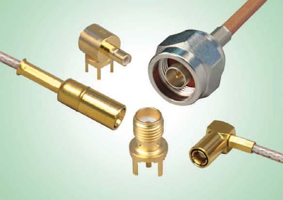
2 Non-Magnetic RF Connectors Connectivity for Table of Contents PAGE TermsandConditions Introduction...5 MMCX Non-Magnetic RF Connectors MCX Non-Magnetic RF Connectors SMA Non-Magnetic RF Connectors SMB Non-Magnetic RF Connectors TypeNNon-MagneticRFConnectors AssemblyInstructions The Johnson Combination - MRI Connectors and Modular Customization CompetitorCrossReference
3 Connectivity for Non-Magnetic RF Connectors EmersonNetworkPowerConnectivitySolutions,Inc. TERMS AND CONDITIONS OF SALE Emerson Network Power Connectivity Solutions, Inc. is herein referred to as the "Seller" and the customer or person or entity purchasing goods ("Goods") from Seller is referred to as the "Buyer." These Terms and Conditions, any price list or schedule, quotation, acknowledgment or invoice from Seller relevant to the sale of the Goods and all documents incorporated by specific reference herein or therein, constitute the complete and exclusive statement of the terms of the agreement governing the sale of Goods by Seller to Buyer. Buyer's acceptance of the Goods will manifest Buyer's assent to these Terms and Conditions. Seller reserves the right in its sole discretion to refuse orders. 1. PRICES: Unless otherwise specified in writing by Seller, the price quoted or specified by Seller for the Goods shall remain in effect for thirty (30) days after the date of Seller's quotation or acknowledgment of Buyer's order for the Goods, whichever occurs first, provided an unconditional authorization from Buyer for the shipment of the Goods is received and accepted by Seller within such time period. If such authorization is not received by Seller within such thirty (30) day period, Seller shall have the right to change the price for the Goods to Seller's price for the Goods at the time of shipment. All prices are exclusive of taxes, transportation and insurance, which are to be borne by Buyer. 2. TAXES: Any current or future tax or governmental charge (or increase in same) affecting Seller's costs of production, sale, or delivery or shipment, or which Seller is otherwise required to pay or collect in connection with the sale, purchase, delivery, storage, processing, use or consumption of Goods, shall be for Buyer's account and shall be added to the price. 3. TERMS OF PAYMENT: Unless otherwise specified by Seller, terms are net thirty (30) days from date of Seller's invoice in U.S. currency. Seller shall have the right, among other remedies, either to terminate this agreement or to suspend further performance under this and/or other agreements with Buyer in the event Buyer fails to make any payment when due, which other agreements Buyer and Seller hereby amend accordingly. Buyer shall be liable for all expenses, including attorneys' fees, relating to the collection of past due amounts. If any payment owed to Seller is not paid when due, it shall bear interest, at a rate to be determined by Seller, which shall not exceed the maximum rate permitted by law, from the date on which it is due until it is paid. Should Buyer's financial responsibility become unsatisfactory to Seller, cash payments or security satisfactory to Seller may be required by Seller for future deliveries and for the Goods theretofore delivered. If such cash payment or security is not provided, in addition to Seller's other rights and remedies, Seller may discontinue deliveries. 4. SHIPMENT AND DELIVERY: While Seller will use all reasonable commercial efforts to maintain the delivery date(s) acknowledged or quoted by Seller, all shipping dates are approximate and not guaranteed. Seller reserves the right to make partial shipments. Seller, at its option, shall not be bound to tender delivery of any Goods for which Buyer has not provided shipping instructions and other required information. If the shipment of the Goods is postponed or delayed by Buyer for any reason, Buyer agrees to reimburse Seller for any and all storage costs and other additional expenses resulting therefrom. Risk of loss and legal title to the Goods shall transfer to Buyer for sales in which the end destination of the Goods is outside of the United States immediately after the Goods have passed beyond the territorial limits of the United States. For all other shipments, risk of loss for damage and responsibility shall pass from Seller to Buyer upon delivery to and receipt by carrier at Seller s shipping point. All shipments are F.O.B. Seller s shipping point. Any claims for shortages or damages suffered in transit are the responsibility of Buyer and shall be submitted by Buyer directly to the carrier. Shortages or damages must be identified and signed for at the time of delivery. Buyer shall inspect Goods delivered to it by Seller immediately upon receipt, and, any course of dealing to the contrary notwithstanding, failure of Buyer to give Seller notice of any claim within 30 days after receipt of such Goods shall be an unqualifiedacceptanceofsuchgoods. 5. LIMITED WARRANTY: Subject to the limitations of Section 6, Seller warrants that the Goods manufactured by Seller will be free from defects in material and workmanship under normal use and regular service and maintenance for a period of one year from the date of shipment of the Goods by Seller, unless otherwise specified by Seller in writing. THIS IS THE SOLE AND EXCLUSIVE WARRANTY GIVEN BY SELLER WITH RESPECT TO THE GOODS AND IS IN LIEU OF AND EXCLUDE ALL OTHER WARRANTIES, EXPRESS OR IMPLIED, ARISING BY OPERATION OF LAW OR OTHERWISE, INCLUDING WITHOUT LIMITATION, MERCHANTABILITY AND FITNESS FOR A PARTICULAR PURPOSE WHETHER OR NOT THE PURPOSE OR USE HAS BEEN DISCLOSED TO SELLER IN SPECIFICATIONS, DRAWINGS OR OTHERWISE, AND WHETHER OR NOT SELLER'S PRODUCTS ARE SPECIFICALLY DESIGNED AND/OR MANUFACTURED BY SELLER FOR BUYER'S USE OR PURPOSE. This warranty does not extend to any losses or damages due to misuse, accident, abuse, neglect, normal wear and tear, negligence (other than Seller's), unauthorized modification or alteration, use beyond rated capacity, unsuitable power sources or environmental conditions, improper installation, repair, handling, maintenance or application or any other cause not the fault of Seller. To the extent that Buyer or its agents has supplied specifications, information, representation of operating conditions or other data to Seller in the selection or design of the Goods and the preparation of Seller's quotation, and in the event that actual operating conditions or other conditions differ from those represented by Buyer, any warranties or other provisions contained herein which are affected by such conditions shall be null and void. If within thirty (30) days after Buyer's discovery of any warranty defects within the warranty period, Buyer notifies Seller thereof in writing, Seller shall, at its option and as Buyer s exclusive remedy, repair, correct or replace F.O.B. point of manufacture, or refund the purchase price for, that portion of the Goods found by Seller to be defective. Failure by Buyer to give such written notice within the applicable time period shall be deemed an absolute and unconditional waiver of Buyer's claim for such defects. All costs of dismantling, reinstallation and freight and the time and expense of Seller s personnel and representatives for site travel and diagnosis under this warranty shall be borne by Buyer unless accepted in writing by Seller. Goods repaired or replaced during the warranty period shall be covered by the foregoing warranty for the remainder of the original warranty period or ninety (90) days from the date of shipment, whichever is longer. Buyer assumes all other responsibility for any loss, damage, or injury to persons or property arising out of, connected with, or resulting from the use of Goods, either alone or in combination with other products/components. Section 5 applies to any entity or person who may buy, acquire or use the Goods, including any entity or person who obtains the Goods from Buyer, and shall be bound by the limitations therein, including Section 6. Buyer agrees to provide such subsequent transferee conspicuous, written notice of the provisions of Sections 5 and LIMITATION OF REMEDY AND LIABILITY: THE SOLE AND EXCLUSIVE REMEDY FOR BREACH OF ANY WARRANTY HEREUNDER OTHER THAN THE WARRANTY PROVIDED UNDER SECTION 7 SHALL BE LIMITED TO REPAIR, CORRECTION OR REPLACEMENT, OR REFUND OF THE PURCHASE PRICE UNDER SECTION 5. SELLER SHALL NOT BE LIABLE FOR DAMAGES CAUSED BY DELAY IN PERFORMANCE AND THE REMEDIES SET FORTH IN THIS AGREEMENT ARE EXCLUSIVE. IN NO EVENT, REGARDLESS OF THE FORM OF THE CLAIM OR CAUSE OF ACTION (WHETHER BASED IN CONTRACT, INFRINGEMENT, NEGLIGENCE, STRICT LIABILITY, OTHER TORT OR OTHERWISE), SHALL SELLER'S LIABILITY TO BUYER AND/OR ITS CUSTOMERS EXCEED THE PRICE PAID BY BUYER FOR THE SPECIFIC GOODS PROVIDED BY SELLER GIVING RISE TO THE CLAIM OR CAUSE OF ACTION. BUYER AGREES THAT IN NO EVENT SHALL SELLER'S LIABILITY TO BUYER AND/OR ITS CUSTOMERS EXTEND TO INCLUDE INCIDENTAL, CONSEQUENTIAL OR PUNITIVE DAMAGES. The term "consequential damages" shall include, but not be limited to, loss of anticipated profits, business interruption, loss of use, revenue, reputation and data, costs incurred, including without limitation, for capital, fuel, power and loss or damage to property or equipment. Buyer expressly acknowledges and agrees that Seller has set its prices and entered into this agreement in reliance upon the limitations of liability and other terms and conditions specified herein, which allocates the risk between Seller and Buyer and form a basis of this bargain between the parties. It is expressly understood that any technical advice furnished by Seller with respect to the use of the Goods is given without charge, and Seller assumes no obligation or liability for the advice given, or results obtained, all such advice being given and accepted at Buyer's risk. 7. PATENTS AND COPYRIGHTS: Subject to the limitations of the secondparagraph of Section 6, Seller warrants that the Goods sold, except as are made specifically for Buyer according to Buyer's specifications, do not infringe any valid U.S. patent or copyright in existence as of the date of shipment. This warranty is given upon the 3
4 Non-Magnetic RF Connectors Connectivity for condition that Buyer promptly notify Seller of any claim or suit involving Buyer in which such infringement is alleged and cooperate fully with Seller and permit Seller to control completely the defense, settlement or compromise of any such allegation of infringement. Seller's warranty as to use patents only applies to infringement arising solely out of the inherent operation according to Seller's specifications and instructions (i) of such Goods, or (ii) of Emerson Network Power Connectivity Solutions, Inc. any combination of Goods acquired from Seller in a system designed by Seller. In the event such Goods are held to infringe such a U.S. patent or copyright in such suit, and the use of such Goods is enjoined, or in the case of a compromise or settlement by Seller, Seller shall have the right, at its option and expense, to procure for Buyer the right to continue using such Goods, or replace them with non-infringing Goods, or modify same to become non-infringing, or grant Buyer a credit for the depreciated value of such Goods and accept return of them. In the event of the foregoing, Seller may also, at its option, cancel the agreement as to future deliveries of such Goods, without liability. 8. EXCUSE OF PERFORMANCE: Seller shall not be liable for delays in performance or for non-performance due to acts of God; acts of Buyer; war; fire; flood; weather; sabotage; strikes or labor disputes; civil disturbances or riots; governmental requests, restrictions, allocations, laws, regulations, orders or actions; unavailability of or delays in transportation; default of suppliers; or unforeseen circumstances or any events or causes beyond Seller's reasonable control. Deliveries or other performance may be suspended for an appropriate period of time or canceled by Seller upon notice to Buyer in the event of any of the foregoing, but the balance of the agreement shall otherwise remain unaffected as a result of the foregoing. If Seller determines that its ability to supply the total demand for the Goods, or to obtain material used directly or indirectly in the manufacture of the Goods, is hindered, limited or made impracticable due to causes set forth in the preceding paragraph, Seller may allocate its available supply of the Goods or such material without obligation to acquire other supplies of any such Goods or material among itself and its purchasers on such basis as Seller determines to be equitable without liability for any failure of performance which may result therefrom. 9. CANCELLATION: Unless otherwise agreed in writing by Seller, orders under this agreement may not be canceled by Buyer for any reason. 10. CHANGES: Buyer may request changes or additions to the Goods consistent with Seller's specifications and criteria. In the event such changes or additions are accepted by Seller, Seller may revise the price and dates of delivery. Seller reserves the right to change designs and specifications for the Goods without prior notice to Buyer, except with respect to Goods being made-to-order for Buyer. Seller shall have no obligation to install or make such change in any Goods manufactured prior to the date of such change. 11. NUCLEAR/MEDICAL: GOODS AND SERVICES SOLD HEREUNDER ARE NOT FOR USE IN CONNECTION WITH ANY NUCLEAR, MEDICAL, LIFESUPPORT AND RELATED APPLICATIONS. Buyer accepts goods and services with the foregoing understanding, agrees to communicate the same in writing to any subsequent purchasers or users and to defend, indemnify and hold harmless Seller from any claims, losses, suits, judgments and damages, including incidental and consequential damages, arising from such use, whether the cause of action be based in tort, contract or otherwise, including allegations that the Seller s liability is based on negligence or strict liability. 12. BUYER S COMPLIANCE WITH LAWS: In connection with the transactions contemplated by this agreement, Buyer is familiar with and shall fully comply with all applicable laws, regulations, rules and other requirements of the United States and of any applicable state, foreign and local governmental body in connection with the purchase, receipt, use, transfer and disposal of the Goods. 13. EXPORT/IMPORT: Buyer agrees that all applicable import and export control laws, regulations, orders and requirements, including without limitation those of the United States and the European Union, and the jurisdictions in which the Seller and Buyer are established or from which Goods and Services may be supplied, will apply to their receipt and use. In no event shall Buyer use, transfer, release, import, export, Goods in violation of such applicable laws, regulations, orders or requirements. patterns do not convey to Buyer, title, ownership interest in, or rights to possession or removal, or prevent their use by Seller for other purchasers, except as otherwise expressly provided by Seller and Buyer in writing with reference to this provision. 15. RETURNED GOODS: Except as otherwise provided with respect to warranty defects in Section 5, advance written permission to return Goods must be obtained from Seller's customer service department. Such Goods must be current, unused, catalogued Goods and must be shipped, transportation prepaid, to the Seller s specified return location. Returns made without proper written permission will not be accepted by Seller. Credit or exchange for such returned Goods will be at the billing price or current price, whichever is lower, from which will be deducted an inspection, restocking and repacking charge and the cost of any reconditioning. Seller reserves the right to inspect Goods prior to authorizing return. 16. BUYER SUPPLIED DATA: To the extent that Seller has been provided by or on behalf of Buyer any specifications, description of operating conditions or other data and information in connection with the selection or design of the Goods, and the actual operating conditions or other circumstances differ from those provided by Buyer and relied upon by Seller, any warranties or other provisions contained herein which are affected by such conditions shall be null and void. 17. DRAWINGS: Seller's prints and drawings (including without limitation, the underlying technology) furnished by Seller to Buyer in connection with this agreement are the property of Seller and Seller retains all rights, including without limitation, exclusive rights of use, licensing and sale. Possession of such prints or drawings does not convey to Buyer any rights or license, and Buyer shall return all copies (in whatever medium) of such prints or drawings to Seller immediately upon request therefore. 18. ASSIGNMENT: Buyer shall not assign its rights or delegate its duties hereunder or any interest herein without the prior written consent of Seller, and any such assignment, without such consent, shall be void. 19. GENERAL PROVISIONS: These terms and conditions supersede all other communications, negotiations and prior oral or written statements regarding the subject matter of these terms and conditions. No change, modification, rescission, discharge, abandonment, or waiver of these terms and conditions shall be binding upon the Seller unless made in writing and signed on its behalf by a duly authorized representative of Seller. No conditions, usage of trade, course of dealing or performance, understanding or agreement purporting to modify, vary, explain, or supplement these terms and conditions shall be binding unless hereafter made in writing and signed by the party to be bound, and no modification or additional terms shall be applicable to this agreement by Seller's receipt, acknowledgment, or acceptance of purchase orders, shipping instruction forms, or other documentation containing terms at variance with or in addition to those set forth herein. Any such modifications or additional terms are specifically rejected and deemed a material alteration hereof. If this document shall be deemed an acceptance of a prior offer by Buyer, such acceptance is expressly conditional upon Buyer s assent to any additional or different terms set forth herein. No waiver by either party with respect to any breach or default or of any right or remedy, and no course of dealing, shall be deemed to constitute a continuing waiver of any other breach or default or of any other right or remedy, unless such waiver be expressed in writing and signed by the party to be bound. All typographical or clerical errors made by Seller in any quotation, acknowledgment or publication are subject to correction. The validity, performance, and all other matters relating to the interpretation and effect of this agreement shall be governed by the law of the state of Missouri. Buyer and Seller agree that the proper venue for all actions arising in connection herewith shall be only in Missouri and the parties agree to submit to such jurisdiction. No action, regardless of form, arising out of transactions relating to this contract, may be brought by either party more than two (2) years after the cause of action has accrued. The U.N. Convention on Contracts for the International Sales of Goods shall not apply to this agreement. 14. TOOLING: Tool, die, and pattern charges, if any, are in addition to the price of the Goods and are due and payable upon completion of the tooling. All such tools, dies and patterns shall be and remain the property of Seller. Charges for tools, dies, and 4
5 Connectivity for Non-Magnetic RF Connectors Introduction Johnson s Non-Magnetic Connector Additions Offer Solutions to MR Imaging Technology Johnson, a product line of Emerson Network Power Connectivity Solutions, has added two new connector product groups to its popular line of Non-Magnetic RF coaxial connectors and cable assemblies. MMCX micro-miniature connectors have been added to satisfy the needs of the RF coil manufacturers that are building smaller coils for MRI equipment. Customized flex coils and array coils can image smaller parts of the body such as wrists, feet, hands and other appendages. The Non-Magnetic MMCX is the perfect micro-miniature connector for small multichannel coil packages as they provide a positive snap-on coupling design with high mating cycles for rugged, high density connectivity. The Type N Non-Magnetic connector provides a perfect RF solution for high Tesla fields considered for future designs. These deep tissue MR images will require the rugged interface of the N connector as well as the tri-alloy plating to eliminate inter-modulation issues. All the connectors in Johnson s Non-Magnetic line are made from high purity copper alloys assuring no ferrous materials are in the connectors manufactured. Emerson Connectivity Solutions continues to work with our customers to develop new solutions as the MR industry transitions to high-end field applications and improved resolution at greater physical depths within the body. Products are offered through authorized distributors and international sales channels including a direct sales force and a network of manufacturers representatives. For more information, please call (800) About Johnson Emerson Network Power Connectivity Solutions, located in Waseca, MN, manufactures Johnson RF Connectors such as Ultra-miniature (UMC), Micro-miniature (MCX, MCX 75, MMCX and SMP), Sub-miniature (SMA, SMB, SMB Mini-75 Ohm, SMK) and Medium (Type N) in the most popular styles including PC Board Mount, End Launch, Bulkhead Mount and Cable Mounts (Flexible, Semi-rigid and Conformable). 5
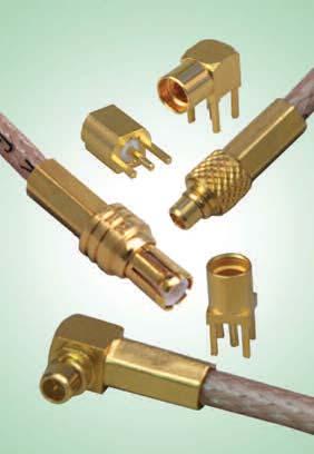
6 MMCX Non-Magnetic RF Connectors Connectivity for ELECTRICAL SPECIFICATIONS Impedance: 50 Ohms Frequency Range: Connectors GHz VSWR: (f = GHz) Straight Right Angle Cable Connectors Cable Connectors.047diaflexible f RG-178, RG-316, RG-316 DS Working Voltage: Connectors VRMS at sea level Dielectric Withstanding Voltage: Connectors VRMS at sea level Insulation Resistance: 1000 megohms min Contact Resistance: (milliohms maximum) After Initial Environmental Center contact (straight cabled connectors and uncabled receptacles) Center contact (right angle cabled connectors) Outer contact (all connectors) Braidtobody N/A Corona Level: Connectors volts min at 70,000 feet Insertion Loss: (db max tested at 1 GHz) Straight cabled connectors Right angle cabled connectors Uncabledreceptacles...N/A RF Leakage: (db minimum, tested at 2.5 GHz) Flexible cable connectors db RF High Potential Withstanding Voltage: 400 VRMS MIN (tested at 4 and 7 MHz) MECHANICAL SPECIFICATIONS Engagement Design:SeriesMMCX Engagement Force: 8lbs.maxaxialengagement,1.4lbs.minaxialdisengagement Contact Retention: 2.0 pounds min. axial force 1inch-ouncemin.torque(uncabledreceptacles) Cable Retention:...AxialForce*(lbs) Torque (in-oz) Connectorsfor.047flexible N/A ConnectorsforRG N/A ConnectorsforRG N/A ConnectorsforRG-316DS N/A Connectorsfor.086Semi-Rigid *Or cable breaking strength whichever is less. Durability: 500cyclesminimum ENVIRONMENTAL SPECIFICATIONS (Meets or Exceeds the Applicable Paragraph of MIL-PRF-39012) Temperature Range: Connectors Cto+165 C Thermal Shock: MIL-STD-202, Method 107, Condition C (except -55 C to +155 C) Corrosion: MIL-STD-202, Method 101, Condition B Shock: MIL-STD-202, Method 213, Condition B Vibration: MIL-STD-202, Method 204, Condition D Moisture Resistance: MIL-STD-202, Method 106 6
.173 (4.39) Crimp Sleeve RG-178/U, 196 135-9402-001.")
 Crimp Insert.047 Dia. Flex 135-9436-001.")
.334 (8.48) Crimp Sleeve RG-178/U, 196 135-9402-111.412 (10.46).334 (8.48) Crimp Sleeve.047 Dia.")
7 Connectivity for MMCX Non-Magnetic RF Connectors For Flexible Cable and PC Mount Straight Crimp Type Plug - Solder or Crimp Contact - Captivated Contact Cable Type Gold Plated A B Termination RG-316/U, 188, 161, (12.93).173 (4.39) Crimp Sleeve RG-178/U, (11.73).137 (3.48) Crimp Insert.047 Dia. Flex (11.73).137 (3.48) Crimp Insert See assembly instructions page 22 Right Angle Crimp Type Plug - Captivated Contact Cable Type Gold Plated A B Termination RG-316/U, 188, 187, 179, 161, (10.46).334 (8.48) Crimp Sleeve RG-178/U, (10.46).334 (8.48) Crimp Sleeve.047 Dia. Flex (8.99).276 (6.98) Crimp Insert See assembly instructions page 23 Straight Jack Receptacle Gold Plated A (2.92) (1.73) Mounting hole layout figure 1 on page 8 7
8 MMCX Non-Magnetic RF Connectors For PC Mount Connectivity for Right Angle Jack Receptacle Gold Plated A (3.94) (1.73) Mounting hole layout figure 1 on page 8 (below) End Launch Jack Receptacle - Surface Contact Gold Plated Packaging Stock Tape and Reel 1000 pcs/reel Recommended land pattern figure 2 on page 8 (below) MOUNTING HOLE Fig 1 Fig 2 8
9 Connectivity for MCX Non-Magnetic RF Connector ELECTRICAL SPECIFICATIONS Impedance: 50 Ohms Frequency Range:...0-6GHz VSWR: (f = GHz) Straight Right Angle Cable Connectors Cable Connectors RG-178cable f f RG-316cable f f Uncabledreceptacles...N/A Working Voltage: (VRMS maximum) Connectors for Cable Type Sea Level 70K Feet RG RG Dielectric Withstanding Voltage: (VRMS minimum at sea level) ConnectorsforRG-178,uncabledreceptacles ConnectorsforRG-316,uncabledreceptacles Insulation Resistance: 10,000 megohms minimum Contact Resistance: (milliohms maximum) After Initial Environmental Centercontact(straightcabledconnectors,uncabledreceptacles) Centercontact(rightanglecabledconnectors) Outercontact Braidtobody N/A Corona Level: (Volts minimum at 70,000 feet) ConnectorsforRG-178uncabledreceptacles ConnectorsforRG-316,uncabledreceptacles Insertion Loss: (db maximum, tested at 1 GHz) Straightcableconnectors...0.1dB Rightanglecableconnectors...0.2dB Uncabledreceptacles...N/A RF Leakage: (db minimum tested at 2.5 GHz) Cableconnectors Uncabledreceptacles...N/A RF High Potential Withstanding Voltage: (VRMS minimum, tested at 4 and 7 MHz) ConnectorsforRG ConnectorsforRG Uncabledreceptacles MECHANICAL SPECIFICATIONS Engagement Design: Compatible with CECC 22220, Series MCX Engagement Force: 5.6 pounds maximum axial force Disengagement Force: 8 pounds maximum axial force, 1 pound min. Contact Retention: 2.3 pounds min. axial force (captivated contacts) 1 inch-ounce min. torque (uncabled receptacles) Cable Retention:...AxialForce*(lbs) ConnectorsforRG ConnectorsforRG ConnectorsforRG316DS...25 *Or cable breaking strength whichever is less. Durability: 500 cycles minimum ENVIRONMENTAL SPECIFICATIONS (Meets or Exceeds the Applicable Paragraph of MIL-PRF-39012) Temperature Range: - 65 C to C Thermal Shock: MIL-STD-202, Method 107, Condition F Corrosion: MIL-STD-202, Method 101, Condition B Shock: MIL-STD-202, Method 213, Condition B Vibration: MIL-STD-202, Method 204, Condition B Moisture Resistance: MIL-STD-202, Method 106 Torque (in-oz) N/A N/A N/A 9

 133-9701-211.110 (2.")
10 MCX Non-Magnetic RF Connectors For Flexible Cables Connectivity for Straight Crimp Type Plug - Solder or Crimp Contact - Captivated Contact Cable Type Gold Plated RG-316/U, 188, RG-316 DS, 188 DS See assembly instructions page 24 Right Angle Crimp Type Plug - Captivated Contact Cable Type Gold Plated Silver Plated RG-316/U, 188, RG-316 DS, 188 DS RG-178/U, See assembly instructions page 24 Straight Jack Receptacle Gold Plated Silver Plated A (3.94) (2.79) Mounting hole layout figure 4 on page 11 10
11 Connectivity for MCX Non-Magnetic RF Connectors For PC Mount Straight Jack Receptacle -.100" Layout Gold Plated Mounting hole layout figure 3 on page 11 (below) Right Angle Jack Receptacle Gold Plated Silver Plated A (3.94) (2.79) Mounting hole layout figure 4 on page 11 (below) End Launch Jack Receptacle - Round Contact Gold Plated Board Thickness (1.57) MOUNTING HOLES Fig 3 Fig 4 11
12 SMA Non-Magnetic RF Connectors Connectivity for ELECTRICAL SPECIFICATIONS Impedance: 50 Ohms Frequency Range: Flexiblecableconnectors GHz Uncabledreceptacles GHz VSWR: (f = GHz) Straight Right Angle Cable Connectors Cable Connectors RG f f RG f f Uncabledreceptacles...N/A Working Voltage: (VRMS maximum) Connectors for Cable Type Sea Level 70K Feet RG RG-58, uncabled receptacles Dielectric Withstanding Voltage: (VRMS minimum at sea level) ConnectorsforRG ConnectorsforRG-58,uncabledreceptacles Insulation Resistance: 5000 megohms minimum Contact Resistance: (milliohms maximum) After Initial Environmental Center contact (straight cabled connectors, uncabled receptacles) Centercontact(rightanglecabledconnectors) Outercontact(allconnectors) N/A Braidtobody N/A Corona Level: (Volts minimum at 70,000 feet) ConnectorsforRG ConnectorsforRG-58,uncabledreceptacles Insertion Loss: (db maximum) Straightflexiblecableconnectors f(ghz), testedat6ghz Rightangleflexiblecableconnectors f(ghz), testedat6ghz Uncabledreceptacles...N/A RF Leakage: (db minimum tested at 2.5 GHz) Flexiblecableconnectors db Uncabledreceptacles...N/A RF High Potential Withstanding Voltage: (VRMSminimum,testedat4and7MHz) ConnectorsforRG Connectors for RG-58, uncabled receptacles MECHANICAL SPECIFICATIONS Engagement Design: MIL-STD-348, Series SMA Engagement/Disengagement Force: 2 inch-pounds maximum Mating Torque: 7 to 10 inch-pounds Coupling Proof Torque: 15 inch-pounds minimum Coupling Nut Retention: 60poundsminimum Contact Retention: 6 lbs. minimum axial force (captivated contacts) 4 inch-ounce minimum torque (uncabled receptacles) Cable Retention:...AxialForce*(lbs) ConnectorsforRG ConnectorsforRG *Or cable breaking strength whichever is less. Durability: 500 cycles minimum Torque (in-oz) N/A N/A ENVIRONMENTAL SPECIFICATIONS (Meets or Exceeds the Applicable Paragraph of MIL-PRF-39012) 12 Temperature Range: - 65 C to C Thermal Shock: MIL-STD-202, Method 107, Condition B Corrosion: MIL-STD-202, Method 101, Condition B Shock: MIL-STD-202, Method 213, Condition I Vibration: MIL-STD-202, Method 204, Condition D Moisture Resistance: MIL-STD-202, Method 106
 0-12.4 GHz 142-9403-011 RG-316 DS, 188 DS 1.15 +.02f (GHz) 0-12.4 GHz 142-9404-011 RG-58/U, 141 1.15 +.01f (GHz) 0-12.")
 0-12.4 GHz 142-9404-101 RG-58/U, 141 1.15 +.02f (GHz) 0-12.")
13 Connectivity for SMA Non-Magnetic RF Connectors For Flexible Cable Straight Crimp Type Plug (3-piece) - Captivated Contact Cable Type VSWR & Freq. Range Gold Plated RG-316/U, 188, f (GHz) GHz RG-316 DS, 188 DS f (GHz) GHz RG-58/U, f (GHz) GHz See assembly instructions page 25 Right Angle Crimp Type Plug - Captivated Contact Cable Type VSWR & Freq. Range Gold Plated Silver Plated RG-316/U, 188, f (GHz) GHz RG-316 DS, 188 DS f (GHz) GHz RG-58/U, f (GHz) GHz See assembly instructions page 25 Straight Crimp Type Blukhead Jack (3-piece) - Captivated Contact Cable Type VSWR & Freq. Range Gold Plated RG-316/U, 188, f (GHz) GHz See assembly instructions page 25 Mounting hole layout figure 5 page 15 13
 Mounting hole layout figure 6 on page 15 Straight Plug Receptacle Frequency Range Gold Plated 0-18 GHz 142-9801-201 Mounting hole layout figure 6 on page 15 Right Angle Jack Receptacle Frequency")
14 SMA Non-Magnetic RF Connectors For PC Mount Connectivity for Straight Jack Receptacle Frequency Range Gold Plated A 0-18 GHz (3.94) 0-18 GHz (2.79) Mounting hole layout figure 6 on page 15 Straight Plug Receptacle Frequency Range Gold Plated 0-18 GHz Mounting hole layout figure 6 on page 15 Right Angle Jack Receptacle Frequency Range Gold Plated 0-18 GHz Mounting hole layout figure 6 on page 15 14
15 Connectivity for SMA Non-Magnetic RF Connectors For PC Mount End Launch Jack Receptacle - Round Contact Frequency Range Gold Plated Board Thickness 0-10 GHz (1.57) End Launch Jack Receptacle - Tab Contact Frequency Range Gold Plated Board Thickness 0-10 GHz (1.57) MOUNTING HOLE Fig 5 Fig 6 15
16 SMB Non-Magnetic RF Connectors Connectivity for ELECTRICAL SPECIFICATIONS Impedance: 50 Ohms Frequency Range: Connectors GHz VSWR: (f = GHz) Straight Right Angle Cable Connectors Cable Connectors RG f f Uncabledreceptacles... N/A Working Voltage: (VRMS maximum) Connectors for Cable Type Sea Level 70K Feet RG-316,uncabledconnectors Dielectric Withstanding Voltage: (VRMS minimum at sea level) ConnectorsforRG-316,uncabledreceptacles Insulation Resistance: 1000 megohms min Contact Resistance: (milliohms maximum) After Initial Environmental Centercontact(straightcabledconnectorsanduncabledreceptacles) Centercontact(rightanglecabledconnectors Outercontact Braidtobody N/A Corona Level: (Volts minimum at 70,000 feet) ConnectorsforRG Uncabledreceptacles...N/A Insertion Loss: (db maximum, tested at 1.5 GHz) Straightcableconnectors dB Rightanglecableconnectors dB Uncabledreceptacles...N/A RF Leakage: (db minimum tested at 2.5 GHz) Cableconnectors...-55dB Uncabledreceptacles...N/A RF High Potential Withstanding Voltage: (VRMSminimum,testedat4and7MHz) ConnectorsforRG Uncabledreceptacles MECHANICAL SPECIFICATIONS Engagement Design: MIL-STD-348, Series SMB Engagement/Disengagement Force: 2 pounds min to 14 pounds maximum axial force Contact Retention: 4 lbs. min axial force (captivated contacts) 1 inch-ounce min torque (uncabled receptacles) Cable Retention:...Axial Force* (lbs) ConnectorsforRG *or cable breaking strength whichever is less. Durability: 500 cycles minimum Torque (in-oz) N/A ENVIRONMENTAL SPECIFICATIONS Temperature Range: -65 Cto+165 C Thermal Shock: MIL-STD-202, Method 107, Condition B Corrosion: MIL-STD-202, Method 101, Condition B Shock: MIL-STD-202, Method 213, Condition B (Meets or Exceeds the Applicable Paragraph of MIL-PRF-39012) 16
 Solder or Crimp Captivated")

17 Connectivity for SMB Non-Magnetic RF Connectors For Flexible Cable Straight Crimp Type Plug - Solder or Crimp Captivated Contact Cable Type Gold Plated RG-316/U, 188, 174, 179, RG-316 DS, 188 DS, 179 DS, 187 DS See assembly instructions page 27 Straight Crimp Type Plug (3-piece) Solder or Crimp Captivated Contact Cable Type Gold Plated RG-316/U, 188, 174, 179, RG-316 DS, 188 DS, 179 DS, 187 DS See assembly instructions page 27 Right Angle Crimp Type Plug - Captivated Contact Cable Type Gold Plated RG-316/U, 188, 174, 179, RG-316 DS, 188 DS, 179 DS, 187 DS See assembly instructions page 27 17
 Mounting hole layout figure 7 on page 18 (below) Right Angle Jack Receptacle Gold Plated 131-9701-301 Mounting hole layout figure 7 on page 18 (below) MOUNTING")
18 SMB Non-Magnetic RF Connectors For Flexible Cable Connectivity for Straight Jack Receptacle Gold Plated A (3.94) (2.41) Mounting hole layout figure 7 on page 18 (below) Right Angle Jack Receptacle Gold Plated Mounting hole layout figure 7 on page 18 (below) MOUNTING HOLE Fig 7 18
19 Connectivity for Type N Non-Magnetic RF Connectors ELECTRICAL SPECIFICATIONS Impedance: 50 Ohms Frequency Range: FlexibleCabledandReceptacles GHz VSWR: (f = GHz) 0-11 GHz StraightFlexibleCabled Max UncabledReceptacles...N/A Working Voltage: (Vrms maximum) Sea Level 70K Feet RG-55/U RG-214,LMR-400Cabled UncabledReceptacles Dielectric Withstanding Voltage: (Vrms minimum) Sea Level RG RG-214,LMR-400Cabled UncabledReceptacles Insulation Resistance: 5000 Megohms minimum Contact Resistance: (milliohms maximum) After Initial Environmental Center Contact StraightCabled(non-captivated) StraightCabled(captivated) UncabledReceptacles OuterContact N/A BraidtoBody N/A Corona Level: 70K Feet RG RG-214,LMR UncabledReceptacles... N/A Insertion Loss: (db, tested at 9 GHz) StraightFlexibleCabled Max RightAngleFlexibleCabled Max UncabledReceptacles... N/A RF High Potential Withstanding Voltage: (Vrms minimum, tested at 4 and 7 MHz) RG-55Cabled RG-214,LMR-400Cabled UncabledReceptacles RF Leakage: (db minimum, tested at 2.5 GHz) CabledConnectors UncabledReceptacles... N/A IMP3: Typically <-90 dbm (tested per IEC Guidelines using 20W inputs swept over MHz MECHANICAL SPECIFICATIONS Axial Force (lbs) Torque (in-oz) CabledConnectors... 6 N/A UncabledReceptacles Cable Retention: (minimum*) Axial Force (lbs) Torque (in-oz) RG-55 Cabled N/A RG-214,LMR-400Cabled N/A * Or cable breaking strength, whichever is less ENVIRONMENTAL SPECIFICATIONS Engagement Design: MIL-STD-348A, Series N Durability: 500 Cycles minimum Engagement/Disengagement Force: 6 inch-pounds maximum Mating Torque: 7 to 10 inch-pounds Bulkhead Mounting Nut Torque: 15 inch-pounds recommended Coupling Proof Torque: 15 inch-pounds minimum Coupling Nut Retention: 100 pounds minimum Contact Retention: (minimum - captivated contacts only) 19

 1.003 (25.48) RG-9/U, 214 1.35 Max, 0-9 GHz 1.50 Max, 9-11 GHz 138-9418-107 1.")
 LMR-400, BELDEN 9913 1.30 Max, 0-11 GHz 138-9349-407.997 (25.")
20 TypeNNon-MagneticRFConnectors For Flexible Cable Connectivity for Straight Crimp Type Plug Solder or Crimp Contact Fig A Fig B Cable Type VSWR & Freq. Range Tri-Alloy Plated Figure RG-55/U, 142, 223, Max, 0-11 GHz A LMR-400, BELDEN Max, 0-11 GHz B See assembly instructions page 28 Right Angle Crimp Type Plug Captivated Contact Cable Type VSWR & Freq. Range Tri-Alloy Plated A B RG-55/U, 142, 223, Max, 0-9 GHz 1.50 Max, 9-11 GHz (31.83) (25.48) RG-9/U, Max, 0-9 GHz 1.50 Max, 9-11 GHz (34.67) (28.32) See assembly instructions page 28 Straight Crimp Type Bulkhead Jack Solder or Crimp Contact Cable Type VSWR & Freq. Range Tri-Alloy Plated A RG-55/U, 142, 223, Max, 0-11 GHz (23.95) LMR-400, BELDEN Max, 0-11 GHz (25.32) Mounting hole layout figure 8 on page 21 See assembly instructions page 29 20
21 Connectivity for Type N Non-Magnetic RF Connectors For Bulkhead and Flange Mount Rear Mount Bulkhead Jack Receptacle Freq. Range Tri-Alloy Plated 0-11 GHz Mounting hole layout figure 8 on page 21 (below) 4-Hole Flange Mount Jack Receptacle Flush Dielectric Freq. Range Tri-Alloy Plated 0-11 GHz Mounting hole layout figure 9 on page 21 (below) MOUNTING HOLE Fig 8 Fig 9 21
22 MMCX Non-Magnetic RF Connectors Assembly Instructions Connectivity for MMCX Straight Plug for RG-316 and RG-316 DS Size Flexible Cable 1. Identify connector parts. (3 piece parts) 2. Strip cable jacket to dimensions shown. Do not nick braid or center conductor during strip operations. Tin center conductor if contact will be solder attached. Do not tin center conductor if contact is to be crimp attached. Slide crimp sleeve onto cable jacket. 3. Assemble contact onto cable as shown. Solder attachment: Solder contact to center conductor. Care should be taken that excess solder is not applied. Crimp attachment: Crimp contact to center conductor using Johnson hand tool and die set Crimp location should be centered between end of contact and cross-hole. Crimp attachment to solid center conductor cables is not recommended. 4. Slide body assembly over contact and under braid, then seat firmly onto contact as shown. The body assembly will snap over the contact barb. The cable may have to be held in a soft jawed clamping fixture. Slide crimp sleeve forward and crimp using recommended crimp die hex. Cable Group Part No. Crimp Die Hex RG-316/u, 188, (3.25) RG-316 DS, 188 DS (3.83) MMCX Straight Plug for.047 (1.19) Diameter and RG-178 Size Flexible Cable 1. Identify piece parts. (3 piece parts) 2. Strip cable jacket to dimensions shown. Do not nick braid or center conductor during strip operations. 3. Slide crimp insert over braid and against jacket, fold braid around crimp insert as shown. Strip dielectric to dimension shown. Tin center conductor if contact is to be soldered attached. Do not tin center conductor if contact is to be crimp attached. 4. Assemble contact assembly onto cable as shown. Solder attachment: Solder contact to center conductor. Care should be taken that excess solder is not applied. Crimp attachment: Crimp contact to center conductor using Johnson hand tool and die set Crimp location should be centered between end of contact and cross-hole. Crimp attachment to solid center conductor cables is not recommended. 5. Slide body assembly over contact and crimp insert, then seat firmly as shown. Crimp body using recommended crimp die hex. Maintain forward pressure on cable while crimping. Cable Group Part No. L Crimp Die Hex.047 Flexible (3.43).105 (2.67) x.250 (6.35) W RG-178/U, (4.67).105 (2.67) x.250 (6.35) W 22
23 Connectivity for MMCX Non-Magnetic RF Connectors Assembly Instructions MMCX Right Angle Plug for RG-178 and RG-316 Size Flexible Cable 1. Identify piece parts. (3 piece parts) 2. Strip cable jacket to dimensions shown. Do not nick braid or center conductor during strip operations. Tin center conductor. Slide crimp sleeve onto cable jacket. 3. Flair braid and assemble crimp stem of body subassembly under braid onto cable making certain that the cable center conductor enters contact slot as shown. Arrange braid uniformly around crimp stem. Slide crimp sleeve over braid and crimp securely using recommended crimp hex. 4. Solder center conductor to contact through rear access port. Use a minimum amount of solder for a full fillet joint. 5. Press end cap into body access port using.156 (3.96) diameter flat punch or Johnson assembly tool Cable Group Part No. Crimp Die Hex A B C RG-178, (2.67) RG-316/U, 188, 187, (3.25) MMCX Right Angle Plug for.047 (1.20) Diameter Size Flexible Cable with Crimp Insert 1. Identify piece parts. (3 piece parts) 2. Strip cable jacket to dimensions shown. Do not nick braid or center conductor during strip operations. 3. Slide crimp insert over braid and against jacket. Fold braid around crimp insert as shown. Strip cable dielectric to dimension shown. Tin center conductor. 4. Slide body assembly over cable and crimp insert, then seat firmly so cable dielectric butts against contact as shown. Crimp body using recommended crimp hex. Maintain forward pressure on cable while crimping. 5. Solder contact to center conductor through rear access port. Use a minimum amount of solder for a full fillet joint. 6. Press end cap into access port using.156 (3.96) diameter flat punch or Johnson assembly tool Cable Group Part No. Crimp Die Hex.047 Flexible (2.67) 23
24 MCX Non-Magnetic RF Connectors Assembly Instructions Connectivity for MCX Crimp Type Straight Connectors for Flexible Cable 1. Identify connector parts. (3 piece parts) 2. Strip cable to dimensions shown. Do not nick braid or center conductor. Tin center conductor if contact is to be solder attached. Do not tin center conductor if contact is to be crimp attached. Slide heat shrink (as applicable) and crimp sleeve onto jacket of cable. 3. Assemble contact onto cable as shown. Solder attachment. Solder contact to center conductor through solder hole using.020 (0.51) diameter solder. Use a minimum of solder for a good joint. Crimp attachment. Crimp contact to center conductor using a miniature 8 indent tool with positioner Crimp location should be centered between end of contact and cross hole. Crimp attachment to solid center conductor cable is not recommended. 4. Flair braid and slide body assembly over contact and under braid. Then seat body assembly firmly onto contact. (RG-178 is non-captivated, RG-316 incorporates snap-fit captivation.) The cable may have to be held in a clamping fixture. Arrange braid uniformly around crimp stem. Slide crimp sleeve forward and crimp using recommended crimp tool. Slide heat shrink forward and shrink (as applicable). Cable Group Part No. Crimp Die Hex RG-316/U, 188, (3.25) RG-316 DS, 188 DS (3.83) MCX Crimp Type Right Angle Plugs for Flexible Cable 1. Identify connector parts. (4 piece parts). 2. Strip cable to dimensions shown. Do not nick braid or center conductor. A wire stripper of correct size is recommended for this step. Twist stranded center conductor into tight bundle and tin (optional). Slide crimp sleeve onto cable as shown. 3. Flare braid and slide cable into body making certain that the cable dielectric bottoms against center contact. Solder: Solder center conductor to contact through the side access ports and hole in center contact. Use a minimum amount of solder for a full fillet joint..015 (0.38) diameter solder is recommended. Crimp: Crimp Contact Attachment Crimp contact using dieset in tool frame. 4. Arrange braid uniformly around crimp stem. Slide crimp sleeve over braid and access ports. Crimp securely using recommended hex size and crimp tool. Cable Group Part No. Crimp Die Hex RG-316/U, 188, / (3.25) RG-316 DS, 188 DS (3.83) RG (2.67) 24
25 Connectivity for SMA Non-Magnetic RF Connectors Assembly Instructions SMA Type Straight Plugs For Flexible Cable - Crimp for Solder Contacts 1. Identify connector parts. (3 piece parts except bulkhead) 2. Strip cable to dimensions shown. Do not nick braid or center conductor. Tin center conductor if contact will be solder attached. Do not tin center conductor if contact is to be crimp attached. A wire stripper of correct size is recommended for this step. Slide heat shrink (as applicable) and crimp sleeve onto jacket of cable. 3. Assemble contact onto cable as shown. Solder Attachment: Solder contact to center conductor through solder hole using.020 (0.51) diameter solder. Use a minimum amount of solder for a good joint. Crimp Attachment: Crimp contact to center conductor using Johnson Hand Tool , setting #2, with positioner Crimp location should be centered between end of contact and X-hole. Crimp attachment to solid center conductor cables is not recommended. 4. Flare braid and slide body assembly over contact and under braid. Then seat body assembly firmly onto contact. The cable may have to be held in a clamping fixture. Arrange braid uniformly around crimp stem. Slide crimp sleeve forward and crimp using recommended crimp tool. Slide heat shrink forward and shrink (as applicable). Cable Group Part No. Crimp Sleeve Hex Size RG-316/U, 188, (3.25) RG-316 DS, 188 DS (3.83) RG-58/U, (5.41) SMA Crimp Type Right Angle Plugs for Flexible Cable 1. Identify connector parts. (3 piece parts) 2. Strip cable to dimensions shown. Do not nick braid or center conductor. A wire stripper of correct size is recommended for this step. Twist stranded center conductor into tight bundle and tin (optional). Slide crimp sleeve onto cable as shown. 3. Flare braid and slide cable into body making certain that the cable insulation bottoms on center contact. Solder center conductor to contact through the rear access port. Use a minimum amount of solder for a full fillet joint..020 (0.51) diameter solder is recommended. 4. Arrange braid uniformly around crimp stem. Slide crimp sleeve over braid and crimp securely using recommended crimp tool. Place expansion cap in access port and seat with.187 (4.75) diameter flat punch. Shrink heat shrink tubing over crimp sleeve if applicable. Cable Group Part No. Crimp Sleeve Hex Size RG-316/U, 188, / (3.25) RG-316 DS, 188 DS (3.83) RG-58/U, / (5.41) 25
26 SMB Non-Magnetic RF Connectors Assembly Instructions Connectivity for SMB 3-Piece Straight Plugs 1. Identify connector parts. (3 piece parts): Crimp sleeve, body assembly and contact 2. Strip cable to dimensions shown. Do not nick braid or center conductor. Tin center conductor if contact will be solder attached. Do not tin center conductor if contact is to be crimp attached. Slide heat shrink (as applicable) and crimp sleeve onto jacket of cable. 3. Assemble contact onto cable as shown. Solder Attachment: Solder contact to center conductor through solder hole using.015 (0.38) diameter solder. Use a minimum amount of solder for a good joint. Crimp Attachment: A miniature 8 indent crimp tool is recommended. Crimp location should be centered between end of contact and X-hole using positioner Crimp attachment to solid center conductor cables is not recommended. 4. Flare braid and slide body assembly over contact and under braid. Then seat body assembly firmly onto contact. The cable may have to be held in a clamping fixture. Arrange braid uniformly around crimp stem. Slide crimp sleeve forward and crimp using recommended crimp tool. Slide heat shrink forward and shrink (as applicable).. Cable Group Part No. Crimp Sleeve Hex Size RG-316/U, 188, 174, 179, (3.25) RG-316 DS, 188 DS, 179 DS, 187 DS (3.83) 26
27 Connectivity for SMB Non-Magnetic RF Connectors Assembly Instructions SMB Straight Crimp Type Straight Plugs for Flexible Cable 1. Identify connector parts. (2 piece parts) 2. Strip cable to dimensions shown. Do not nick braid or center conductor. A wire stripper of correct size is recommended for this step. Twist stranded center conductor into tight bundle and tin. Slide crimp sleeve onto cable as shown. 3. Flare braid and slide cable into body making certain that the cable dielectric bottoms against center contact. Solder Attachment: Solder center conductor to contact through the side access ports and hole in center contact. Use a minimum amount of solder for a full fillet joint..020 (0.51) diameter solder is recommended. Crimp Attachment: Crimp contacts with dieset in tool frame. Cable Group Part No. Crimp Sleeve Hex Size RG-316/U, 188, 174, 179, (3.25) RG-316 DS, 188 DS, 179 DS, 187 DS (3.83) SMB Right Angle Crimp Type Straight Plugs for Flexible Cable 1. Identify connector parts. (3 piece parts: crimp sleeve, body assembly and expansion cap.) 2. Strip cable to dimensions shown. Do not nick braid or center conductor. A wire stripper of correct size is recommended for this step. Twist stranded center conductor into tight bundle and tin (optional). Slide crimp sleeve onto cable as shown. 3. Flare braid and slide cable into body assembly making certain that the cable insulation bottoms on center contact. Arrange braid uniformly around crimp stem of body assembly. Slide crimp sleeve over braid and crimp securely using recommended crimp tool. 4. Solder center conductor to contact through the rear and side access ports. Use a minimum amount of solder for a good joint..020 (0.51) diameter solder is recommended. Place expansion cap in access port and seat with a.125 (3.17) diameter flat punch. Snap cover ring over side access port. Cable Group Part No. Crimp Sleeve HeSize RG-316/U, 188, 174, 179, (3.25) RG-316 DS, 188 DS, 179 DS, 187 DS (3.83) 27
28 TypeNNon-MagneticRFConnectors Assembly Instructions Connectivity for Type N Straight Plug Crimp Style for Flexible Cable 1. Identify connector parts (3 piece parts). 2. Strip cable to dimensions shown. Do not nick center conductor. A wire stripper of correct size is recommended for this step. Tin center conductor if contact will be solder attached. Do not tin center conductor if contact will be crimp attached. Slide crimp sleeve onto jacket of cable. 3. Assemble plug contact onto cable as shown. Plug contact should butt against cable dielectric during attachment. Solder Attachment: Solder plug contact to center conductor through solder hole using.020 (0.51) diameter flux core solder wire. Use a minimum amount of solder for a good joint. Crimp Attachment: Crimp plug contact to center conductor using Johnson ergonomic hand crimp frame with recommended hex size die set. Crimp location should be on end of plug contact next to cable dielectric. Crimp attachment to solid center conductor cables is not recommended. 4. Flare braid and slide plug connector assembly over plug contact and under braid. Seat plug connector assembly firmly onto contact. Arrange braid uniformly around crimp stem. Slide crimp sleeve forward and crimp using Johnson ergonomic hand crimp frame with recommended hex size die set. Maintain forward pressure on cable while crimping. Cable Group Part No. A B Sleeve Hex Contact Hex RG-55/U, 142, 223, (7.65).140 (3.56).213 (5.41).068 (1.73) LMR-400, BELDEN (9.78).170 (4.32).429 (10.90).116 (2.95) Type N Right Angle Plug Crimp Style For Flexible Cable 1. Identify connector parts (3 piece parts). 2. Strip cable to dimensions shown. Do not nick center conductor. A wire stripper of correct size is recommended for this step. Twist stranded center conductor into tight bundle and tin (optional). Slide crimp sleeve onto jacket of cable. 3. Flare braid and slide plug connector assembly over cable dielectric and under braid. Make sure cable dielectric bottoms against plug contact as shown for RG-55/U cable group. Maintain a slight gap between Dielectric and Contact for Cable Group RG-9. Solder center conductor to contact through rear access port. Use a minimum amount of solder for a full fillet joint. 4. Arrange braid uniformly around crimp stem. Slide crimp sleeve forward and crimp using Johnson ergonomic hand crimp frame with recommended hex size die set. Screw end cap into access port. Cable Group Part No. A "B" "C" Crimp Sleeve Hex Size RG-55/U, 142, 223, (20.02).300 (7.62).071 (1.80).213 (5.41) RG-9, (10.90).350 (8.89).135 (3.43).429 (10.90) 28
29 Connectivity for Type N Non-Magnetic RF Connectors Assembly Instructions Type N Bulkhead Jack Crimp Style for 142, and LMR-400 Flexible Cable 1. Identify connector parts (6 piece parts). 2. Strip cable to dimensions shown. Do not nick center conductor. A wire stripper of correct size is recommended for this step. Tin center conductor if contact will be solder attached. Do not tin center conductor if contact will be crimp attached. Slide crimp sleeve onto jacket of cable. 3. Assemble jack contact onto cable as shown. Jack contact should butt against cable dielectric during attachment. Solder Attachment: Solder jack contact to center conductor through solder hole using.020 (0.51) diameter flux core solder wire. Use a minimum amount of solder for a good joint. Crimp Attachment: Crimp jack contact to center conductor using Johnson ergonomic hand crimp frame with recommended hex size die set. Crimp location should be on end of jack contact next to cable dielectric. Crimp attachment to solid center conductor cables is not recommended. 4. Flare braid and slide bulkhead jack connector assembly over jack contact and under braid. Seat bulkhead jack connector assembly firmly onto contact. Arrange braid uniformly around crimp stem. Slide crimp sleeve forward and crimp using Johnson ergonomic hand crimp frame with recommended hex size die set. Maintain forward pressure on cable while crimping. 5. Add gasket, lock washer and mounting nut when installing connector to panel. Crimp Sleeve Contact Cable Group Part No. A B C Hex Size Hex Size RG-55/U, 142, 223, (7.87).389 (9.88).135 (3.43).213 (5.41).068 (1.73) LMR-400, BELDEN (9.78).400 (10.16).165 (4.19).429 (10.90).116 (2.95) Assembly Tool Crimp Frame Die Set


30 Non-Magnetic RF Connectors Connectivity for The Johnson Combination - MRI Connectors and Modular Customization Johnson, a product line of Emerson Network Power Connectivity Solutions, offers the Medical Industry a combination of expertise in Non-Magnetic and Custom Modular Connectivity. A broad line of Non-Magnetic connector families is available for high density RF signal transmission in the MR Lab environment. MMCX, MCX, SMA, SMB and N Type coaxial Interfaces can be employed to both deliver the power and return multi-coil imaging resolution. MMCX multi-pack modules can provide.150" (3.81mm) center to center coax arrays that terminate to micro-coaxial cables. Modules can be configured as rails, blocks and cable handles that provide rapid RF coil hookup and change out. Johnson's vertically integrated production facility guarantees near unity permeability of raw materials, plating and packaging. Non-Magnetic quality is specified in high purity materials and monitored throughout the connector build process. Emerson Connectivity Solutions continues to work with our customers to develop new solutions as the MR industry transitions to high-end field applications and improved resolution at greater physical depths within the body. Products are offered through authorized distributors and International sales channels including a direct sales force and a network of manufacturers' representatives. For more information, please call (800) About Johnson Emerson Network Power Connectivity Solutions, located in Waseca, MN, manufactures Johnson RF Connectors such as Ultra-miniature (UMC), Microminiature (MCX, MCX 75, MMCX and SMP), Sub-miniature (SMA, SMB, SMB Mini-75 Ohm, SMK) and Medium (Type N) in the most popular styles including PC Board Mount, End Launch, Bulkhead Mount and Cable Mounts (Flexible, Semi-rigid and Conformable). 30
Non Magnetic Connectors Product Catalog
 Non Magnetic Connectors Product Catalog Introduction Johnson s Non-Magnetic Connector Additions Offer Solutions to MR Imaging Technology Johnson, a product line of Cinch Connectivity Solutions, has expanded
Non Magnetic Connectors
 Non Magnetic Connectors Johnson Components builds coaxial connectors using innovative materials and design to provide Mil Spec Performance at a commercial price. Now we offer our Non Magnetic Connectors
Non-Magnetic Connectors Product Catalog
 Non-Magnetic Connectors Product Catalog Non-Magnetic RF Connectors Table of Contents PAGE Terms and Conditions............................3-4 Introduction......................................5 MMCX Non-Magnetic
Stainless Steel SMA Connectors Product Catalog
 Stainless Steel SMA Connectors Product Catalog Connectivity...for Stainless Steel SMA Connectors Connectivity...for Johnson Stainless Steel SMA Connectors meet or exceed the performance requirements of
MCX - 75 Ohm Connectors
 133-8333-001 4 133-8333-401 4 133-8334-001 4 133-8334-401 4 133-8433-001 3 133-8433-101 3 133-8434-001 3 133-8445-001* 3 133-8445-101* 3 133-8701-201 5 133-8701-211 5 133-8701-301 6 133-8701-311 6 133-8701-401
SMA - 50 Ohm Connectors
 Alphabetical Index 142-0593-001 6 142-0593-006 6 142-0593-401 6 142-0593-406 6 142-0594-001 6 142-0594-006 6 142-0594-401 6 142-0594-406 6 142-0693-001 4 142-0693-006 4 142-0693-051 5 142-0693-056 5 142-0693-101
SMA One Piece Semi-Rigid Connectors
 SMA One Piece Semi-Rigid Connectors The Johnson captivated solderless contact connectors for semi-rigid cable provide a unique solution for high frequency cable assemblers. As compared to standard solder-on
RF/Microwave Connectors & Cable Assemblies
 RF/Microwave Connectors & Cable Assemblies Emerson Network Power Connectivity Solutions Connectivity Solutions To our valued customers: For over 80 years, Johnson Components and Cambridge Products have
MCX Miniature Coaxial Connectors
 ONLINE CATALOG MCX Miniature Coaxial Connectors 104 John W. Murphy Drive P.O. Box 510 New Haven, CT 06513 www.aepconnectors.com e-mail: aepsales@aepconnectors.com Mating Interfaces MCX Miniature Coaxial
PERFORMANCE SPECIFICATION SHEET CONNECTORS, PLUGS, ELECTRICAL, COAXIAL, RADIO FREQUENCY (SERIES SMA (CABLED) - PLUG, PIN CONTACT, CLASS 2)
 - PLUG, PIN CONTACT, CLASS 2)") INCH-POUND MIL-PRF-39012/55G 6 February 2008 SUPERSEDING MIL-PRF-39012/55G 6 January 2006 PERFORMANCE SPECIFICATION SHEET CONNECTORS, PLUGS, ELECTRICAL, COAXIAL, RADIO FREQUENCY (SERIES SMA (CABLED) -
INCH-POUND MIL-PRF-39012/55G 6 February 2008 SUPERSEDING MIL-PRF-39012/55G 6 January 2006 PERFORMANCE SPECIFICATION SHEET CONNECTORS, PLUGS, ELECTRICAL, COAXIAL, RADIO FREQUENCY (SERIES SMA (CABLED) -
PERFORMANCE SPECIFICATION SHEET
 INCH-POUND 5 October 2016 SUPERSEDING w/amendment 2 July 2016 PERFORMANCE SPECIFICATION SHEET CONNECTORS, PLUG, ELECTRICAL, COAXIAL, RADIO FREQUENCY, SERIES SMA (CABLED) PIN CONTACT, RIGHT ANGLE, CLASS
Automatic Connector MHV Connectors MHV Introduction MHV series connectors Contents Polarized mating interfaces Anti-Rock mating interfaces
 Automatic s 2004 Automatic. All rights reserved. pdf 1.0 3-18-04 Contents Specifications........................... 2 Straight Cable Plugs...................... 3 Right Angle Cable Plugs...................
Type "N" Connectors. Type "N" Interface Dimensions
 Type "N" Connectors The type N series coaxial connectors were originally designed as medium-size low voltage constant impedance 50 OHM connectors. Type N connectors found immediate popularity for microwave
SMP Connectors. Table of Contents PAGE. Introduction Specifications MountingHoles...7. Applications AssemblyTools...
 SMP Connectors Table of Content Connectivity for Table of Contents PAGE Introduction...3-4 Specifications...5-8 MountingHoles...7 Applications...9-12 AssemblyTools...13 AssemblyInstructions...14-18 CompetitorCrossReference...19
bmam connectors DIVIDER PAGE
 bmam connectors DIVIDER PAGE 4 bmam interface dimensions "E" "D" REF. PLANE "E" REF. PLANE "G" "C".0 REF. 60 "C" "B" "B".0 REF. 0 "F" "D" male, plug INCHES / MILLIMETERS MINIMUM MAXIMUM LTR. IN. MM. IN.
PERFORMANCE SPECIFICATION SHEET CONNECTORS, PLUGS, ELECTRICAL, COAXIAL RADIO FREQUENCY, (SERIES BNC (CABLED), PIN CONTACT, CLASS 2)
, PIN CONTACT, CLASS 2)") INCH-POUND MIL-PRF-39012/16H 16 November 2006 SUPERSEDING MIL-PRF-39012/16G 26 September 1994 PERFORMANCE SPECIFICATION SHEET CONNECTORS, PLUGS, ELECTRICAL, COAXIAL RADIO FREQUENCY, (SERIES BNC (CABLED),
INCH-POUND MIL-PRF-39012/16H 16 November 2006 SUPERSEDING MIL-PRF-39012/16G 26 September 1994 PERFORMANCE SPECIFICATION SHEET CONNECTORS, PLUGS, ELECTRICAL, COAXIAL RADIO FREQUENCY, (SERIES BNC (CABLED),
Series MCX 50 micro miniature connectors
 Series MCX 50 micro miniature connectors Description Content MCX 50 HUBER+SUHNER MCX micro miniature snap-on connectors offer you an excellent blend of size,weight, durability and performance for applications
PERFORMANCE SPECIFICATION SHEET CONNECTORS, PLUGS, ELECTRICAL, COAXIAL RADIO FREQUENCY, (SERIES TNC (CABLED), PIN CONTACT, RIGHT ANGLE, CLASS 2)
, PIN CONTACT, RIGHT ANGLE, CLASS 2)") INCH-POUND MIL-PRF-39012/30H 15 March 2018 SUPERSEDING MIL-PRF-39012/30H w/amendment 3 15 April 2017 PERFORMANCE SPECIFICATION SHEET CONNECTORS, PLUGS, ELECTRICAL, COAXIAL RADIO FREQUENCY, (SERIES TNC
INCH-POUND MIL-PRF-39012/30H 15 March 2018 SUPERSEDING MIL-PRF-39012/30H w/amendment 3 15 April 2017 PERFORMANCE SPECIFICATION SHEET CONNECTORS, PLUGS, ELECTRICAL, COAXIAL RADIO FREQUENCY, (SERIES TNC
HN Connectors. Automatic Connector. Introduction. Contents. 631/ FAX 631/
 Connectors Introduction 2004 Automatic Connector. All rights reserved. pdf 1.0 4-13-04 Contents Specifications........................... 2 Straight Cable Plugs...................... 3 Right Angle Cable
INCH-POUND MIL-PRF-39012/29H w/amendment 3 25 January 2018 SUPERSEDING MIL-PRF-39012/29H w/amendment 2 21 November 2016
 INCH-POUND MIL-PRF-39012/29H 25 January 2018 SUPERSEDING MIL-PRF-39012/29H w/amendment 2 21 November 2016 PERFORMANCE SPECIFICATION SHEET CONNECTORS, RECEPTACLE, ELECTRICAL, COAXIAL, RADIO FREQUENCY, (SERIES
SERIES BNC 50, COAXIAL MINIATURE CONNECTORS
 SERIES BNC 50, COAXIAL MINIATURE CONNECTORS DESCRIPTION CONTENTS PAGE HUBER+SUHNER BNC is still one of the most popular connector series, featuring a two stud bayonet coupling mechanism, which is particularly
INCH-POUND MIL-PRF-39012/28H w/amendment 4 25 January 2018 SUPERSEDING MIL-PRF-39012/28H w/amendment 3 15 April 2017
 INCH-POUND MIL-PRF-39012/28H 25 January 2018 SUPERSEDING MIL-PRF-39012/28H w/amendment 3 15 April 2017 PERFORMANCE SPECIFICATION SHEET CONNECTORS, RECEPTACLES, ELECTRICAL, COAXIAL, RADIO FREQUENCY, (SERIES
PERFORMANCE SPECIFICATION SHEET CONNECTORS, PLUGS, ELECTRICAL, COAXIAL RADIO FREQUENCY, (SERIES BNC (CABLED), PIN CONTACT, CLASS 2)
, PIN CONTACT, CLASS 2)") PERFORMANCE SPECIFICATION SHEET MIL-PRF-39012/16H 03 January 2017 SUPERSEDING MIL-PRF-39012/16H w/amendment 1 20 April 2009 CONNECTORS, PLUGS, ELECTRICAL, COAXIAL RADIO FREQUENCY, (SERIES BNC (CABLED),
PERFORMANCE SPECIFICATION SHEET MIL-PRF-39012/16H 03 January 2017 SUPERSEDING MIL-PRF-39012/16H w/amendment 1 20 April 2009 CONNECTORS, PLUGS, ELECTRICAL, COAXIAL RADIO FREQUENCY, (SERIES BNC (CABLED),
Materials Connector part Material Finish
 Materials Connector part Material Finish Bodies Brass Nickel or Gold Center Contact Male: Brass Gold Female: Brass, Phosphor Bronze, or Beryllium Copper Insulator Delrin or Teflon N/A Crimp ferrule Annealed
MWT-FM. Operation Manual. FM Single Channel Transmitter. man_mwtfm.
 MWT-FM FM Single Channel Transmitter Operation Manual man_mwtfm www.myeclubtv.com CONTENTS FCC COMPLIANCE STATEMENT. 3 INDUSTRY CANADA COMPLIANCE 3 MWT-FM ORIENTATION. 4 SAFETY PRECAUTIONS 5 FINDING FM
Materials Connector part Material Finish
 Materials Connector part Material Finish Bodies Brass Nickel or Gold Center Contact Male: Brass Gold Female: Brass, Phosphor Bronze, or Beryllium Copper Insulator Delrin or Teflon N/A Crimp ferrule Annealed
Electronic M.O.P Card. Instruction Manual Model D
 Electronic M.O.P Card Instruction Manual Model D10341-000 Table of Contents 1. General Description................................................................ 1 2. Specifications.....................................................................
Amphenol RF Connectors
 Amphenol RF Connectors 007 901-9601 SMA PLUGS & ANGLE PLUGS FOR FLEXIBLE CABLE 50X IMPEDANCE Conn. Attachment RG-/U Outer Inner 901-9511-12SF Dbl. Braid RG-316 Plug Br. Solder $17.49 901-9531-12SF Angle
Jul03 Rev C EC
 Product Specification Coaxial BNC Solder Receptacle Connector 108-12079 10Jul03 Rev C EC 0990-0940-03 1. SCOPE 1.1. Content This specification covers the performance, tests and quality requirements for
TNC Connectors. RF Coax Connectors. Product Facts
 Product Facts Hex Crimp and Connectors 50 and 75 ohm commercial versions available Provides excellent performance at frequencies up to 7 GHz ow cost commercial type available type is smaller and lighter
C Connectors. Automatic Connector. Introduction. Contents. C Interface Options. 631/ FAX 631/
 utomatic onnector onnectors Introduction 2004 utomatic onnector. ll rights reserved. pdf 1.0.1 3-23-04 ontents Specifications........................... 2 Straight Plugs...................... 3 Right ngle
Series SMPM-T. Description. Compatibility. Content. Interface dimensions (mm/inches) SMPM-T male (pin contact), smooth bore
 SMPM-T male (pin contact), smooth bore") Series Description The is the smallest threaded open source connector on the market. Its unique and innovative combination of a MIL- STD-348 SMPM female interface connector together with a retractable
Series Description The is the smallest threaded open source connector on the market. Its unique and innovative combination of a MIL- STD-348 SMPM female interface connector together with a retractable
SERIES HPQN CONNECTORS
 SERIES HPQN CONNECTORS 1 DESCRIPTION Patented in 2008 by Anoison Electronics, the HPQN is a quick locking version of the widely used type N connector. By replacing the threaded interface of the original
Low Voltage Multifunctional LED Controller / DMX Decoder. Specification
 Low Voltage Multifunctional LED Controller / DMX Decoder Specification High Power DMX Decoder & Driver Meets DMX 512/1990 Protocol LT-300 can drive up to 8A current on each channel Capable of driving many
Instant 802.3af Gigabit Outdoor PoE Converter. Model: INS-3AF-O-G. Quick Start Guide
 Instant 802.3af Gigabit Outdoor PoE Converter Model: INS-3AF-O-G Quick Start Guide QUICK START GUIDE Introduction Thank you for purchasing the Ubiquiti Networks Instant 802.3af Gigabit Outdoor PoE Converter.
MYE TV Audio Grabber
 Radio MYE TV Audio Grabber Model: MAG98 Operation Manual Man_MAG_V2 www.myeclubtv.com FCC Compliance Statement NOTE: This equipment has been tested and found to comply with the limits for a class B digital
USER INSTRUCTIONS MODEL CSI-200 COAXIAL SYSTEM INTERFACE
 USER INSTRUCTIONS MODEL CSI-200 COAXIAL SYSTEM INTERFACE 9350-7676-000 Rev B, 5/2001 PROPRIETARY NOTICE The RTS product information and design disclosed herein were originated by and are the property of
HDTV SIGNAL AMPLIFIERS. 34 series USER GUIDE GUÍA PARA EL USUARIO MODE D EMPLOI CM-3410 CM-3412 CM-3414 CM-3418
 HDTV SIGNAL AMPLIFIERS 34 series USER GUIDE GUÍA PARA EL USUARIO MODE D EMPLOI CM-3410 CM-3412 CM-3414 CM-3418 Table of Contents Product Overview... 3 Package Contents and Accessories... 3 Instructions...4
HD VIDEO IP STREAMER CT-HDVD-HDSTR-KIT
 www. nacebrands.com HD VIDEO IP STREAMER CT-HDVD-HDSTR-KIT MADE IN CHINA Read this user manual carefully before using this product. Pictures shown in this manual are for reference only. Safety Precaution
OWNER'S MANUAL MYCRO SUB
 OWNER'S MANUAL MYCRO SUB OWNER'S MANUAL MYCRO SUB Features Compact dimensions and high output. Dual coil woofer provides multiple wiring configurations. Recessed connectors allow the enclosure to be used
ENGINEERING COMMITTEE Interface Practices Subcommittee AMERICAN NATIONAL STANDARD ANSI/SCTE
 ENGINEERING COMMITTEE Interface Practices Subcommittee AMERICAN NATIONAL STANDARD ANSI/SCTE 176 2011 Specification for 75 ohm 'MCX' Connector, Male & Female Interface NOTICE The Society of Cable Telecommunications
Enable-IT 821P PoE Extender Quickstart Guide Professional Grade Networking
 ! Enable-IT 821P PoE Extender Quickstart Guide Professional Grade Networking All Rights Reserved 1997-2016 Enable-IT, Inc. INSTALLING THE 821P POE EXTENDER The Enable-IT 821P PoE Extenders have a distance
General Description. SC Configurations
 S onnectors General Description Delta S series connectors are medium-size, 50Ω impedance connectors with 11 16-24 threaded coupling and good power handling capability, particularly those connectors noted
REQUIRED TOOLS. Wire cutters Razor blade Soldering iron Pliers 11/16 Wrench for Tube 18mm Wrench for Ring
 S9122 PWS BNC MALE CABLE MOUNT COMPRESSION CONNECTOR S9022 PWS N TYPE MALE CABLE MOUNT COMPRESSION CONNECTOR S9322 PWS TNC MALE CABLE MOUNT COMPRESSION CONNECTOR The PWS S9122 is a BNC male cable mount
Quick Installation Guide. Indoor / Outdoor Antenna, Antenna Cable & Surge Arrestor
 Quick Installation Guide Indoor / Outdoor Antenna, Antenna Cable & Surge Arrestor Table of Contents... 1 1. Outdoor Antenna Installation... 1 2. How to install the surge arrestor... 4 3. Weatherproof tape
Ultra-Grip 2 Crimp Connector Hand Tool Kit for Coaxial Cable Connectors, Powerpole Connectors, Insulated and Non-Insulated Crimp Terminals
 Ultra-Grip 2 Crimp Connector Hand Tool Kit for Coaxial Cable Connectors, Powerpole Connectors, Insulated and Non-Insulated Crimp Terminals DXE-UT-KIT-CRMP2 DXE-UT-KIT-CRMP-INS-Revision 0a DX Engineering
SINCE User Manual 7 DAY PROGRAMMABLE DIGITAL TIMER MODEL PS-100. The best solutions for automation and protection.
 SINCE 1973 User Manual 7 DAY PROGRAMMABLE DIGITAL TIMER MODEL PS-100 The best solutions for automation and protection www.nassarelectronics.com Description The PS-100 is a 7 day programmable digital timer
Ultra-Grip Crimp Connector Hand Tool Kit for Coaxial Cable and Powerpole Connectors
 Ultra-Grip Crimp Connector Hand Tool Kit for Coaxial Cable and Powerpole Connectors DXE-UT-KIT-CRIMP DXE-UT-KIT-CRIMP-INS-Revision 2b DX Engineering 2014 1200 Southeast Ave - Tallmadge, OH 44278 USA Phone:
Installation and Operation Manual. for the. SM-6 Programmable Stereo Mixer
 for the Copyright 1996 2001 by Broadcast Tools, Inc. All rights reserved. Except as permitted under the United States Copyright Act of 1976, no part of this document may be reproduced or distributed without
Protect Your Hearing!
 Protect Your Hearing! The US Government's Occupational Safety and Health Administration (OSHA) has specified the following permissible noise level exposures: Duration Per Day In Hours Sound Level dba,
User Manual TLS HDMI Switch 4/1 MHL
 875222 User Manual TLS HDMI Switch 4/1 MHL HDMI IN IR SW 4 3 2 1 OUT SBL/SBR SL/SR CEN/SUB FL/FR DIG AUDIO SPDIF DC 5V HDMI OUT 1 2 HDMI IN 3 MLH 4 8 875222 HDMI Switch 4/1 MHL Thank you for purchasing
Enable-IT 824WP Outdoor Waterproof PoE Extender Kit Quickstart Guide Professional Grade Networking
 ! Enable-IT 824WP Outdoor Waterproof PoE Extender Kit Quickstart Guide Professional Grade Networking All Rights Reserved 1997-2018 Enable-IT, Inc. INSTALLING THE 824WP GIGABIT ETHERNET EXTENDER The Enable-IT
In-Wall Control Mount for ipod Touch
 In-Wall Control Mount for ipod Touch INTRODUCTION The Mirage KP-iOS is an in-wall system that allows ipod touch (4th generation) to become a semi-permanent fixture in your wall. The system allows you to
SECTION 10 BNC / BNC 75 HDTV / BNC-TRX R141 / R142 / R266
 SECTION 10 10 BNC / BNC 75 HDTV / BNC-TRX R141 / R142 / R266 Contents Introduction... 10-4 to 10-5 Interfaces... 10-6 to 10-7 Characteristics... 10-8 to 10-11 Finder guide...10-12 to 10-13 COMPOSITE BNC
QMA and QN connectors, patented products, become some real standard for the RF Telecommunications industry.
 CONTENTS PAGE Introduction...4-5 Characteristics... 6 Plugs...7-9 Jacks...9- Receptacles...-4 Adapters...4-6 Protective cap... 6 Panel drilling... 7 Receptacles packaging... 8 Assembly instructions...9-30
The Custom Interconnect Leader TM
 LC Series.5.188.685 ELECTRICAL Nominal Impedance: Frequency Range: Voltage Rating: Dielectric Withstanding Voltage: Insulation Resistance: VSWR: 50 ohms DC to 1.0 GHz 5,000 volts rms 3,000 volts rms 5,000
SUHNER QMA SUBMINIATURE CONNECTORS
 SUHNER QMA SUBMINIATURE CONNECTORS Description Content Page SUHNER QMA coaxial connectors are available with 50 Ω impedance. The frequency range extends to 11 GHz, depending on the connector and cable
Model Number Structure
 Cycle Control Units CSM DS_E_7_1 Refer to Safety Precautions for All Power Controllers. Used in Combination with the to Enable High-precision Temperature Control Use cycle control to achieve power control
SECTION 9 BNC/BNC 75 HDTV/BNC-TRX R141/R142/R266 SIMPLIFICATION IS OUR INNOVATON. Visit for more information
 SECTION 9 BNC/BNC 75 HDTV/BNCTRX R141/R142/R266 SIMPLIFICATION IS OUR INNOVATON Visit www.radiall.com for more information Contents BNC Introduction... 94 to 95 Interfaces... 96 to 97 Characteristics...98
Table of Contents. Introduction Pin Description Absolute Maximum Rating Electrical Specifications... 4
 Table of Contents Introduction... 1 Pin Description... 2 Absolute Maximum Rating... 3 Electrical Specifications... 4 Mechanical Specifications... 5 Thermal Specifications... 6 Over Temperature Protection...
Enable-IT 865 Q PRO Gigabit Professional Grade PoE Extender Kit Quickstart Guide
 Enable-IT 865 Q PRO Gigabit Professional Grade PoE Extender Kit Quickstart Guide INSTALLING THE 865 Q PRO POE EXTENDER KIT The Enable-IT 865 Q PRO PoE Extenders have a distance restriction of 1,500ft (458m)
MWCS-AT9-MYA MYE 900MHz (Wireless) CableSAT
 CableSAT") MWCS-AT9-MYA MYE 900MHz (Wireless) CableSAT MYE Entertainment 1-661-964-0217 www.myeclubtv.com All Rights Reserved 2016 Transmitter Installation ***Before using CableSAT, the TV tuner needs to be scanned
MWCS-AT9-MYA MYE 900MHz (Wireless) CableSAT MYE Entertainment 1-661-964-0217 www.myeclubtv.com All Rights Reserved 2016 Transmitter Installation ***Before using CableSAT, the TV tuner needs to be scanned
Clearview. Classic Cassettes. Installation Manual. Clearview Classic (HD) High Density. Part #: Rev: A Updated:
 High Density. Part #: Rev: A Updated:") Clearview Classic Cassettes Installation Manual Clearview Classic (HD) High Density Part #: 016781 Rev: A Updated: 11.2014 7050 Winnetka Ave N Minneapolis, MN 55428 Direct: 763.476.6866 National: 800.422.2537
Clearview Classic Cassettes Installation Manual Clearview Classic (HD) High Density Part #: 016781 Rev: A Updated: 11.2014 7050 Winnetka Ave N Minneapolis, MN 55428 Direct: 763.476.6866 National: 800.422.2537
APSPB PUSH BUTTON ZERO Installation Manual
 APSPB PUSH BUTTON ZERO Installation Manual CARDINAL SCALE MFG. CO. 8527-0579-0M Rev A 203 E. Daugherty, Webb City, MO 64870 USA Printed in USA 12/14 Ph: 417-673-4631 Fax: 417-673-2153 www.detectoscale.com
Series SK (2.92 mm) prec. submini. connectors
 prec. submini. connectors") Series prec. submini. connectors Description Content HUBER+SUHNER SK connectors are precision connectors for microwave applications up to 40 GHz. They are intermateable with series SMA and PC 3.5. They
Series prec. submini. connectors Description Content HUBER+SUHNER SK connectors are precision connectors for microwave applications up to 40 GHz. They are intermateable with series SMA and PC 3.5. They
XW3D. Simple Wiring of Sensor Actuators. Connector Terminal Boxes. Specifications. Materials and Finish. Connection Combinations
 Terminal Boxes XWD CSM_XWD_DS_E Simple Wiring of Sensor Actuators Greatly reduce wiring in combination with the Smartclick XS. Insert the connector and turn / of a turn to lock the connectors. Higher rated
Coaxial Cable Feedline Choke Kit - 50 Ω
 Coaxial Cable Feedline Choke Kit - 50 Ω COM-CFC-50K COM-CFC-50K-INS-Revision 2a COMTEK SYSTEMS 2013 P.O. Box 1491 - Akron, OH 44309-1491 USA Phone: (800) 777-0703 Technical Support and International: (330)
E8Y. Micropressure Sensor with Easy-to-Read Digital Display. Differential Pressure Sensor. Ordering Information. Sensors
 Differential Sensor Micropressure Sensor with Easy-to-Read Digital Repeat accuracy of ±1% FS (setting resolution: 0.01 kpa), high-precision pressure control available. Compact design (31 mm) saves mounting
Installation and Operation Manual. for the. IPC-2, Twin stereo level matching interface
 Preliminary Preliminary Preliminary Preliminary for the Copyright 1996 by All rights reserved. Except as permitted under the United States Copyright Act of 1976, no part of this document may be reproduced
MWCS-CC9-MYA MYE 900MHz CableSAT TV Channel Changer
 MWCS-CC9-MYA MYE 900MHz CableSAT TV Channel Changer MYE Entertainment 1-661-964-0217 www.myeclubtv.com All Rights Reserved 2017 Channel Changer Transmitter Installation ***Before using CableSAT, the TV
ASSEMBLY, INSTALLATION, AND REMOVAL OF CONTACTS AND MODULES
 ASSEMBLY, INSTALLATION, AND REMOVAL OF CONTACTS AND MODULES FOR 75 OHM AND 75 OHM HD COAXIAL CONTACTS AND MODULES Table of Contents SECTION 1 RECEIVER CONTACT ASSEMBLY INSTRUCTIONS SECTION 2 ITA CONTACT
Metal Electrode Meter
 Metal Electrode Meter INSTRUCTION MANUAL FOR Metal Electrode Meter MODEL 2900 Serial # Date PO Box 850 Carlsborg, WA 98324 U.S.A. 360-683-8300 800-426-1306 FAX: 360-683-3525 http://www.a-msystems.com Version
ARRIS Solutions Inc. TERMS OF USE ARRIS SOFTWARE APPLICATIONS
 ARRIS Solutions Inc. TERMS OF USE ARRIS SOFTWARE APPLICATIONS (Effective as of February 10, 2015) PLEASE READ CAREFULLY This ARRIS Solutions, Inc. Terms of Use Agreement (this "Agreement") is a legal agreement
Data Sheet of SAW Components
 Data Sheet of SAW Components Note : Murata SAW Component is applicable for Cellular /Cordless phone (Terminal) relevant market only. Please also read caution at the end of this document. Package Dimensions
HD-1x2-4K. Ultra Slim 6G HDCP 2.2 1x2 HDMI Splitter. Factor Electronics
 HD-1x2-4K Ultra Slim 6G HDCP 2.2 1x2 HDMI Splitter 4159 McConnell Drive Burnaby B.C. Canada V5A-3J7 Toll Free: 1-855-204-1388 info@factorelectronics.com 1 Thank you for purchasing this product. For optimum
CN12 Technical Reference Guide. CN12 NTSC/PAL Camera. Technical Reference Guide PCB Rev
 CN12 NTSC/PAL Camera Technical Reference Guide PCB Rev 1.0 www.soc-robotics.com Copyright 2010. SOC Robotics, Inc. 1 Manual Rev 0.90 Warranty Statement SOC Robotics warrants that the Product delivered
Surface Mount Multilayer Ceramic Capacitors for RF Power Applications
 Surface Mount Multilayer Ceramic Capacitors for RF Power Applications FEATURES Case size 0505,, 2525, and 3838 Available Ultra-stable, high Q dielectric material Available Lead (Pb)-free terminations code
Surface Mount Multilayer Ceramic Chip Capacitors for High Temperatures 200 C
 Surface Mount Multilayer Ceramic Chip Capacitors for High Temperatures 200 C DESIGN TOOLS (click logo to get started) FEATURES Case size 0402, 0505, 0603, 0805, Available High frequency / high temperature
R87B. Box Fan. Comprehensive Lineup of Single, Double, and Triple Axial Fans with Easy One-step Mounting. Model Number Structure. Ordering Information
 Box Fan R87B CSM_R87B_DS_E_4_4 Comprehensive Lineup of Single, Double, and Triple Axial Fans with Easy One-step Mounting Mounts in a square cutout and conceals the hole-cut to simplify installation work.
Low Loss RG 402 Equivalent
 421-671 Low Loss RG 402 Equivalent Section 10 Low Loss RG 402 Equivalent In applications that require the bendability of solid dielectric, but with the low loss that only a low density Teflon dielectric
1X4 HDMI Splitter with 3D Support
 AV Connectivity, Distribution And Beyond... VIDEO WALLS VIDEO PROCESSORS VIDEO MATRIX SWITCHES EXTENDERS SPLITTERS WIRELESS CABLES & ACCESSORIES 1X4 HDMI Splitter with 3D Support Model #: SPLIT-HDM3D-4
RF CONNECTORS RFC SERIES
 Introduction: Adam Tech s RFC series RF connectors are a comprehensive assortment of Radio Frequency signal connectors in standard, miniature, sub-miniature, micro miniature and surface mount styles. Included
Surface Mount Multilayer Ceramic Capacitors for RF Power Applications
 Surface Mount Multilayer Ceramic Capacitors for RF Power Applications FEATURES Case size 0505 and and 2525 Available Ultra-stable, high Q dielectric material Available Lead (Pb)-free terminations code
CIRCULATOR & ISOLATOR APPLICATION NOTES: IM CONTROL PANEL APPLICATION NOTES: CAVITY RESONATOR APPLICATION NOTES:
 1 CIRCULATOR & ISOLATOR APPLICATION NOTES: Circulated power is the same as forward handling power. To insure stated specifications, loads are dynamically matched to circulators during manufacturing. Isolation
7RF Connectors. RF Connectors. Table of Contents
 RF Connectors Table of Contents Military Qualified Introduction.........................................................7003 N Series Connectors MIL-C-3902 50 Ohm.....................................................
Instruction Manual. 2.4G Digital Wireless Four Channel Transmitter System RVS-554W. Reverse With Confidence 1
 Instruction Manual 2.4G Digital Wireless Four Channel Transmitter System RVS-554W 1 NOTE! Please read all of the installation instructions carefully before installing the product. Improper installation
Fiber Converters TFC-1000 Series. ŸQuick Installation Guide (1) ŸTechical Specifications (4)
 ŸTechical Specifications (4)") Fiber Converters TFC-1000 Series ŸQuick Installation Guide (1) ŸTechical Specifications (4) 1. Before You Start Package Contents ŸFiber Converter ŸMulti-Language Quick Installation Guide ŸPower Adapter
Fiber Converters TFC-1000 Series ŸQuick Installation Guide (1) ŸTechical Specifications (4) 1. Before You Start Package Contents ŸFiber Converter ŸMulti-Language Quick Installation Guide ŸPower Adapter
SIRIUS HOME ANTENNA USER GUIDE & WARRANTY
 SIRIUS HOME ANTENNA FOR USER GUIDE & WARRANTY Thank you for purchasing the Monster SIRIUS Home Antenna for SIRIUS Satellite Radio. Your new antenna lets you enjoy SIRIUS Satellite Radio in the comfort
PERFORMANCE SPECIFICATION SHEET
 INCH-POUND MIL-PRF-39012/2H 20 December 2016 SUPERSEDING MIL-PRF-39012/2H w/mendment 3 12 March 2012 PERFORMNCE SPECIFICTION SHEET CONNECTORS, PLUGS ND RECEPTCLES, ELECTRICL, COXIL, RDIO FREQUENCY, (SERIES
blink USER GUIDE Bluetooth capable Reclocker Wyred 4 Sound. All rights reserved. v1.0
 blink Bluetooth capable Reclocker USER GUIDE Wyred 4 Sound. All rights reserved. v1.0 Table of Contents READ FIRST Important 1 Package contents 1 About the blink Bluetooth Streamer/Reclocker 1 Connectivity
Enable-IT Port Extended Gigabit Ethernet PoE DSLAM Quickstart Guide
 Enable-IT 8955-8 Port Extended Gigabit Ethernet PoE DSLAM Quickstart Guide All Rights Reserved 1997-2015 Enable-IT, Inc. INSTALLING THE 8955 ETHERNET POE DSLAM - 8 PORT The Enable-IT 8955 Extended Gigabit
DA8-T DA8-T MANUAL
 J C F A U D I O MANUAL 1.0 contact@jcfaudio.com www.jcfaudio.com Safety Information Do not repair, modify, service this device except in the manner in which it is described in this manual. Doing so can
RF CONNECTORS. Adam Technologies, Inc. ORDERING INFORMATION 1 01 D RoHS RFC SERIES INSULATOR A V A I L A B L E
 INTRODUCTION: Adam Tech s RFC series RF connectors are a comprehensive assortment of Radio Frequency signal connectors in standard, miniature, sub-miniature, micro miniature and surface mount style. Included
Surface Mount Multilayer Ceramic Chip Capacitors for High Frequency
 Surface Mount Multilayer Ceramic Chip Capacitors for High Frequency ELECTRICAL SPECIFICATIONS Note Electrical characteristics at 25 C unless otherwise specified FEATURES Case size 0402, 0603, 0805 Available
User Manual HDBaseT 70 Transmitter & Receiver
 875730 User Manual HDBaseT 70 Transmitter & Receiver Thank you for purchasing this product. For optimum performance and safety, please read these instructions carefully before connecting, operating or
Coaxial Cable Termination
 Coaxial Cable Termination RF one-step BNC/TNC connectors Applications RF one-step BNC/TNC connectors are single-piece assemblies for terminating the center conductor and the braid of a broad range of coaxial
AMERICAN NATIONAL STANDARD
 Interface Practices Subcommittee AMERICAN NATIONAL STANDARD ANSI/SCTE 129 2017 Drop Passives: Bonding Blocks (Without Surge Protection) NOTICE The Society of Cable Telecommunications Engineers (SCTE) Standards
12G Broadcast connectors
 12G Broadcast connectors Delivering 12G in a single punch www.coax-connectors.com Welcome to COAX 12G BNC Plug return loss COAX Connectors Ltd is a leading UK designer, manufacturer and supplier of high
Ultra-Grip 2 Crimp Connector Hand Tool Kit for Crimp Coaxial Cable Connectors, Powerpole Connectors, Insulated and Non-Insulated Crimp Terminals
 Ultra-Grip 2 Crimp Connector Hand Tool Kit for Crimp Coaxial Cable Connectors, Powerpole Connectors, Insulated and Non-Insulated Crimp Terminals DXE-UT-KIT-CRMP2 DXE-UT-KIT-CRMP-INS-Revision 0d DX Engineering
Enable-IT 860C PRO Coax Gigabit Professional Grade Ethernet Extender Kit Quickstart Guide
 ! Enable-IT 860C PRO Coax Gigabit Professional Grade Ethernet Extender Kit Quickstart Guide All Rights Reserved 1997-2017 Enable-IT, Inc. INSTALLING THE 860C PRO COAX ETHERNET EXTENDER The Enable-IT 860C