A I R 3 RADIO CONSOLE
|
|
|
- Shonda Briggs
- 5 years ago
- Views:
Transcription
1 AI 3 ADIO CONSO Technical Guide June 2010
2 CONSO FATUS Overview Console Features ach AI 3 console has two Input panels and one Master panel. The Input panel consists of six faders with associated switches. The Master panel has a PHON section, a CONTO section, a HADPHON section, and a STUDIO section. ach section is described below. The basic purpose of the console is to take some of the many audio signals that are wired to the console inputs, and generate several outputs that combine these inputs in various groups and at various degrees of loudness, or signal strength. The typical application is in a radio station where it is desired to develop the signals that the station will broadcast (the on air signal), as well as several additional signals for recording and monitoring. page 2
3 Dimensions 28.4" 4.3" 15.4" 15.4" 1.6" page 3
4 DB-25 J-45 BAANCD T H A T H INPUT H T B T H STAT OPTO A/B A / B F T STAT PGM 1 PGM 2 F A D OGIC P G M F T CU FT C MUT/ AI TAY DIP SW PGM 1 ACN PGM 2 ACN CU ACN MUT/TAY STAT PGM 1 PGM 2 TB PGM 1 T PGM 1 T PGM 2 T PGM 2 T MIC 1 TB OGIC P G M / T B F T TIM SUM STAT OPTO DIP SW MUT/TAY PGM 1 T MONO PGM 1 T MONO PGM 2 T MONO PGM 2 T MONO DB-25 PIN 25 J-45 BAANCD H CA TO HYBID INPUT CHANN PGM 1 MON PGM 2 T MON PGM 2 T MON XT T MON XT T MON VU MTS ON AI TAY OGIC DIV V U F T CU OGIC OGIC TIM TIM XT PGM 2 N.O. DY AY CU SNS PGM 1 MTS TO BIDG PGM 2/SWITCHD MTS TO BIDG PIN 10 DB-25 PIN 9 TO TAY D TO BIDG PGM 1 ACN PGM 2 ACN J-45 BAANCD H CA FOM HYBID F A D PHON P G M F T TIM TIM TIM TIM CU DIP SW PGM 1 T MON H J-45 BAANCD PGM 1 T MON PGM 1 OUT H PGM 2 T MON H PGM 2 T MON PGM 2 OUT H CU FT OGIC USB CODC CU ACN CU SNS FOM COMPUT USB TO CONN PATCH OUT J-45 C TO STUDIO TB OGIC TB XT IN PGM 1 PGM 2 DIM O INTUPT DIP SW TB TO STUDIO STUDIO MUT/TAY INPUT 1 MUT/TAY INPUT 12 MUT/TAY PHON CU TO C NAB CU SNS DIP SW OGIC XT IN PGM 1 PGM 2 ON AI TAY C MUT SPIT CU MOD DIP SW CONTO OOM PGM 1 T MON PGM 1 T MON PGM 2 T MON PGM 2 T MON XT T MON XT T MON S T F T V F T J-45 ST OUT PGM 1 T MON PGM 1 T MON PGM 2 T MON PGM 2 T MON XT T MON XT T MON C F T V F T J-45 C OUT TIM MIC 1 TB TB TO PHON MIC 1 H PAMP C MIC 1 J-45 C MIC 1 DB-25 PINS 11,12 MIC 2 H PAMP TIM GUST TB TO CU/C CU ACN C MUT CU FT J-45 MIC 2 V FT STUDIO/GUST MIC 2 TO XT CU AMP DB-25 PINS 7,8 CU MB SPK CU MON XTNA IN H XT T MON XT IN H XT T MON BAANCD J-45 HADPHON CU SNS V F T OGIC CU MON HDPN OUT HDPN JACK SPIT CU MOD JUMP AI 3 System Flow Diagram page 4
5 APPNDICS AI 3 Performance Specifications FQUNCY SPONS ine (20Hz-20kHz) +/-0.1dB Mic (20Hz-20kHz) +/-0.1dB DYNAMIC ANG ine, unity gain Mic, 54dB gain NOIS ine THD+N (20Hz-20kHz) 113dB 100dB -89dBu ine, -4dBu <0.003% Mic, -50dBu <0.02% MAXIMUM INPUT Mic -6dBu BUS COSSTAK 20Hz 20kHz -100dB -60dB STO SPAATION 1kHz OFF ISOATION 1kHz 20kHz DIMNSIONS -60dB -115dB -95dB Width 28.4 Depth 15.4 Height (rear) 4.4 Height (front) 1.6 HADOOM above -4dB 24dB Specifications and features subject to change without notice. page 5
 input that goes directly to control room or studio. The AI 3 also has one analog (+4dBu balanced) input dedicated to use as a telephone caller input.")
6 CONSO FATUS Inputs The AI 3 console is designed to handle up to 12 analog stereo pro level (+4dBu balanced) inputs, two mono microphone (-50dBu nominal) inputs, and one external stereo line level (+4dBu balanced) input that goes directly to control room or studio. The AI 3 also has one analog (+4dBu balanced) input dedicated to use as a telephone caller input. Analog Mono Mic evel Inputs These inputs are used to connect to microphones, which typically put out signals at relatively low signal strength, and therefore require more amplification (increase in signal strength) to be properly audible in the output. Mic level sources are wired to a 6- position plug terminal located on the rear of the console. On the rear of the console also are a pair of J-45 connectors used for MIC outputs, and the MIC 1 and MIC 2 GAIN trimpots for adjusting the level of each microphone input independently. xample: with a microphone input of at the port, gain trim can set levels from -22dBu to +16dBu (note maximum preamp gain is +76dB) at the PGM 1 or PGM 2 output. These microphone connections are to the inputs of two internal microphone preamplifiers. In order to actually hear the microphone audio, the microphone preamplifier outputs must be wired to the desired line inputs that feed the faders you will use to control the microphone levels. ooking at the rear of the console, there are two J-45 connectors towards the left end of the console labeled MIC 1 OUT and MIC 2 OUT. These are the outputs, respectively, of the MIC 1 preamp and MIC 2 preamp. In a typical installation you will want to feed the mic signal to both left and right sides of the stereo line input. For this reason, we have duplicated the MIC OUT signal as both left and right, so that a simple J-45 patch cord will carry the mic signal to both left and right sides of the stereo input of whichever line input you want the mic to feed. Analog Stereo ine evel Inputs These inputs are typically used to connect to machines, such as tape decks, cart machines, CD players, etc., that provide analog outputs. As mentioned above, you can also feed these inputs from the outputs of the internal mic preamps. Outputs The console main analog outputs include two Program stereo buses (PGM 1 and PGM 2). The Program stereo outputs can be programmed to mono outputs via dipswitch SW 1 (described in the Console Internal Programming section). Monitor outputs include a stereo Control oom output, a stereo Studio output, a mono cue output, and a stereo headphone jack. page 6

7 CONSO FATUS The console s mono cue signal feeds the internal speaker in the meterbridge, and also provides the cue signal used to interrupt Control oom and headphones, if such interrupt has been enabled by the installer. USB Port The console contains a USB 2.0 interface, available via the USB Type B connector on the rear panel, to enable audio to pass between the console and a USB port on a computer. Internally, dipswitches select either PGM 1 or PGM 2 as the audio from the console to the computer (see Console Internal Programming ). Audio coming back from the computer via USB shows up as a stereo analog signal on the USB ANAOG OUT J-45 connector. From there, the audio can be patched to any line input, or to the external input. Using the USB Port... Any computer having a USB port and installed drivers capable of passing and utilizing digital audio data should work with the Air 3 USB port. Use a cable having a USB Type B connector on the Air 3 end and a connector on the other end that will mate with the computer s USB port; this will typically be a USB Type A connector.... With a MAC In general, this will be a plug-and-play process. The main concern is to choose the USB Audio Codec under System Preferences>Sound as desired for audio input and/or output. Then simply start the application.... With a Windows PC When you first connect the Air 3 USB port to a PC running Windows you will see the famous found new hardware sequence of messages. At some point this sequence should end with a message that the new hardware is installed and ready to use. Setting up any given application to use the Air 3 USB port will depend on the application itself. Generally, you will need to select the appropriate device from a list of devices in a Preferences dialog. As an example, let s look at WinAmp, a free software application used by millions to play back audio streams from a network (or the Internet), or to play audio streams into a network. To play audio from the Air 3 on the computer: Install the free inein plugin for WinAmp. Under Preferences - Input select the inein plugin from the Input list and click Configure, then find the USB Audio Codec in the list of available devices and note its corresponding device number, which you will need below. In WinAmp, choose Play U... nter line://dev=n where n is the device value that you discovered above. page 7
8 CONSO FATUS Now when you click Play, WinAmp will play the Air 3 audio on the output device selected in WinAmp. This could be speakers, a sound card, or even an output stream. To play audio from the computer on the Air 3: Under WinAmp Preferences - Output select an output plugin and click Configure, then select the USB Audio Codec as the device. Play the desired computer audio with WinAmp and the audio will appear at the USB ANAOG OUT connector on the back of the Air 3. You must patch this output to the desired fader (using the appropriate connector from the INPUTS bank), or to the XT IN if desired, to route the audio. Other Computers If your computer does not use one of the above operating systems, or otherwise behaves differently than described above, consult the documentation for that computer, operating system, and/or application. General Considerations If any problems are encountered, please consider the following points: The audio that is output from the Air 3 on the USB port depends on the setting of the internal dipswitches that select between PGM 1 and PGM 2 as the source (see Console Internal Programming ). The audio coming back into the Air 3 on the USB port is available at the USB ANAOG OUT, which must be patched to a line input if you want it to come up on a fader, or to the XT IN if you want it available only in the monitors, or to some external device if that s where you want it to show up. If you are not able to get the audio into or out of the USB port, check the USB cable, its connections at both ends, and the port selection settings in the application you are using. If you have the audio flowing where you want and it suddenly becomes intermittent or disappears, check the USB cable and the connections at both ends. Once you have the USB audio under control it is a good idea to make a record of the application being used, including its version number, the audio direction (into or out of the computer), and all the settings that were required to make it work. This information will be invaluable if you later have to troubleshoot the USB audio, or set it up on another computer. Mute and Tally The console has the ability to mute the control room output. The console also has an ON AI tally output that is used to drive user-provided external circuitry that will in turn operate the control room on air indicator. This tally is automatically activated whenever the control room mute is activated. Thus, turning on any module that activates the control room mute also turns on the ON AI tally. Whenever this tally is activated the ON AI indicator in the meterbridge will also illuminate. See the Console Programming Options section for details. page 8

9 CONSO FATUS Console Programming Options All programming (except for the headphone split cue option and selection of audio to feed to an external computer via the USB port) is made via three PCB mounted dipswitches located on the console s rear panel. One dipswitch (PGM/CU switch) is on the top left side of the rear, and programs the control room cue, the studio dim function, and the mono program outputs. The two other dipswitches (C MUT/AI TAY) are in between the two groups of INPUTS J-45 connectors, and activate C mute and AI TAY. PGM/CU Dipswitch When a PGM/CU dipswitch position is up it is ON. Cue Interrupt The dipswitch pos. 1, when activated, sends cue to the control room. Split Cue, Control oom The dipswitch pos. 2, when activated, allows a summed (+) version of the regular program to be sent to the right side of the C monitor stereo output, while CU is sent to the left side. Split Cue, Headphone Consoles are normally programmed at the factory for CU to appear on the left channel, while + sum of the control room output appears on the right. This can be changed with jumper J1 on the back side of the Master Panel. The jumper normally spans pins 2 and 3 of the jumper header. To defeat this split cue option, move the jumper to span pins 1 and 2 instead. Then cue will interrupt both sides of the headphones. Studio Dim The dipswitch pos. 3, when activated, allows normal studio audio to DIM (drop -20dB in level) when talkback to studio is engaged. If this dipswitch is not activated, the normal studio audio is completely interrupted by the MIC 1 audio when talkback to studio is engaged. If the studio is programmed to DIM talkback audio could presumably make it from the studio monitor speakers to the open studio mic. page 9


10 CONSO FATUS Program Mono The dipswitch pos. 4-7, when activated, sums the left and right POGAM channels and sends + to the appropriate channel: Pos. 4 - sends + of the PGM 1 to the PGM 1 T channel; Pos. 5 - sends + of the PGM 1 to the PGM 1 T channel; Pos. 6 - sends + of the PGM 2 to the PGM 2 T channel; Pos. 7 - sends + of the PGM 2 to the PGM 2 T channel. USB Source Dipswitches (internal) Dipswitch 2 on the CONA3-4 board is used to determine whether PGM 1 or PGM 2 will feed the USB link. Positions 1 and 3 should be on to feed USB with PGM 1, while positions 2 and 4 should be on to feed USB with PGM 2. If PGM 1 is to be used, the PGM 2 positions should be off, and if PGM 2 is to be used, the PGM 1 positions should be off. DO NOT activate both PGM 1 and PGM 2 simultaneously! C MUT/AI TAY Dipswitches When a C MUT/AI TAY dipswitch position is down it is ON. C Mutes An input channel can be programmed to mute the control room speakers when the channel is ON. Positions 1 through 12 and caller (13) of the dipswitches, when activated, automatically mute the console s control room speakers when the corresponding channels 1 through 13 are turned ON. This is done to prevent feedback from the C announcer s mic. At the same time the ON AI D in the center of the meterbridge will light up. page 10
11 CONSO FATUS On Air Tally For controlling the on-air tally function, a relay is provided. The tally is activated when any channel set for C mute is turned on or put into cue. The relay connections are available at the OGIC DB-25 connector mounted on the rear of the console. Connect the on-air light to the external user-provided relay. Do not bring on-air light AC connections to any pin of any connector on the console. TYPICA CONTO OOM ON-AI TAY CICUIT US-SUPPID AY TIGGD BY CONSO C MUT CICUI INTNA AI TAY AY N.C. N.O. COM 30VDC 2A max CONNCTO PIN ON "OGIC" DB-25 PIN 10 PIN 9 1N CG B40240 or equiv. relay + YOU POW SUPPY AY CICUIT POWD BY US SUPPID XTNA SUPPY page 11

12 AI 3 Console ayout page 12

13 CONTOS AND FUNCTIONS Input Panel (IP-AI3) Controls and Functions The Input panel of the AI 3 console has six identical strips representing six input channels. page 13

14 CONTOS AND FUNCTIONS Source Select ach input channel accepts two analog stereo sources: A and B, switched at the top of the panel. The A/B button will be lit when source B is selected. Program Assign Output switches assign the selected source signal to any combination of the console s two stereo Program outputs PGM 1 and PGM 2. The button will be lit when the source is assigned to its respective bus. To remove a source from the bus, press the button again; the light will go off to indicate that the source is no longer assigned to that bus. NOT that when the console is powered up all input channels will be off, with source A selected, and assigned to PGM 1. ecessed rear panel trimpots adjust the left and right levels of PGM 1 and PGM 2 outputs. Cue Button A CU switch places the channel s signal on the console s cue bus, where it may be heard on the meterbridge mounted cue speaker, as an interrupt to the console operator s headphones, and as an interrupt to the control room monitor speakers, if so programmed. Press the CU button. The channel s input signal will be included in the console s CU output at a level that is independent of the FAD setting, and the button will light. The fader does not need to be turned ON. To remove a fader from cue, press the CU BUTTON again; the light will go off to indicate the channel is no longer assigned to cue. Fader evel is set by a long-throw fader. The fader is the sliding mechanism that determines how strong is the presence of the input in some of the various console outputs. If the fader is all the way down (that is, pulled toward the console operator), the signal will not be present in either of the two program main buses to which it is assigned. As the fader is moved up (that is, pushed away from the console operator) the signal will appear more strongly in each of the main buses to which it is assigned. ON Button The ON button turns the channel on and off by means of electronic switching and can simultaneously start external source machines. The channel is ON when the ON button is lit. These can also be programmed (as mentioned in the previous chapter) to activate control room mute and on air tally. page 14

15 CONTOS AND FUNCTIONS Master Panel (MST-AI3) The Master panel includes the Caller Input, Control oom monitor, Studio monitor, and Meters sections. page 15
16 CONTOS AND FUNCTIONS Caller Input The caller section is used for the telephone call-in talk segments, and controls the audio for the caller. The caller signal enters the console from your station hybrid. The caller feed can be either or both of the two Program buses. The caller feed will never contain the caller s own voice. A recessed rear panel trimpot adjusts the caller output level. Program Assign Output switches assign the caller to any combination of the console s two Program outputs (PGM 1 and PGM 2), and permit live talk-ins. Pressing either of the two program switches causes the caller s audio to be included in the output mix for that bus, at a level dependent on the FAD setting, as long as the caller section is ON. The button will be lit when the caller is assigned to its respective bus. To remove the caller from a bus to which it is currently assigned, press the button again; the light will go off to indicate that the caller is no longer assigned to that bus. CU Button The CU button allows interviewing the caller prior to airing by including the caller s voice in the console s cue bus, where it may be heard on the meterbridge mounted cue speaker. TB Button When the TB switch is pressed (it is momentary action), the microphone (MIC 1) will interrupt the regular caller signal, thus allowing the DJ to talk to the caller prior to airing. Fader The long-throw fader sets the caller s signal level. If a fader is all the way down the caller s voice will not be present in either of the two Program buses (PGM 1 and PGM 2) to which the phone is assigned. As the fader is moved up the signal will appear more strongly in each of the main buses to which the phone is assigned. The fader position will also affect the strength of the caller in the cue output. ON Button The ON button determines if the phone channel is ON or OFF. The channel is ON when the ON button is lit. The button can also be used to provide external start logic for the hybrid. If the phone channel is OFF, caller signal will not be present in any main bus output, regardless of the status of the POGAM ASSIGN buttons or the position of the fader. If the phone channel is OFF its signal will still be present in the cue output if it has been assigned to cue. page 16
 C speakers. Additionally, pressing the caller TB switch sends the MIC 1 signal to the caller output.")
17 CONTOS AND FUNCTIONS Caller Set-Ups Pre-air segment communication between the console operator (DJ) and callers is aided by the CU button, which places the caller s voice on the console s cue speaker and headphones, and (if so programmed) C speakers. Additionally, pressing the caller TB switch sends the MIC 1 signal to the caller output. A typical call-in segment might proceed as follows: Caller phones in, DJ picks up off-air during a track play to set up the call. He places the caller in CU, and talks to the caller by pressing the TB button. Neither the DJ mic nor the phone channel need to be ON for two-way communication. When he is ready to take the call on-air, the DJ makes sure his mic and phone are assigned to PGM 1 or PGM 2 and turns them ON. He then deactivates caller CU to hear the normal feed. page 17
18 CONTOS AND FUNCTIONS Control oom Monitor This is the console operator s monitor that allows the operator to listen to the console s two stereo Program outputs and an external stereo line level input. This section of the console includes the monitor level controls for the control room, headphone, and cue circuits. In a typical radio application the console is located in the Control oom. Speakers in the Control oom allow the console operator to listen to the console bus outputs to be assured that the console is performing as desired. These speakers are fed by a stereo signal from the console s Control oom output. In addition to the Control oom output, the operator may also desire to listen to specific isolated faders via the cue system and the console s internal cue speaker, or may want to listen via headphones. Thus, the control room monitor consists of the above mentioned level controls, along with two program assign (PGM 1 and PGM 2) buttons, and an external input (XT) button. In some instances the console operator may also be performing talent whose voice will be heard over the radio. The operator s microphone may thus provide a part of the signal that is going out over the air. If that signal is the one being monitored with the Control oom speakers, there is the potential for feedback. The amplified signal from the Control oom speakers is picked up by the microphone and amplified to a new, higher, level, which then is once again picked up by the microphone. The signal quickly rises to an ear-splitting screech. To prevent this, the operator s microphone is normally set to MUT the Control oom output to prevent the occurrence of feedback. The master CU circuit drives a meterbridge-mounted speaker through a built-in power amp, and can be programmed to interrupt control room feed, or provide a split feed (program mono sum to right, cue to left) to the control monitor speakers. It also automatically interrupts the headphone feed. Program Select Pressing either of the two program (PGM 1 or PGM 2) switches allows the operator to listen to the selected output bus. The button will be lit when the monitor is assigned to its respective bus. page 18
19 CONTOS AND FUNCTIONS XT Switch Pressing the XT switch allows the operator to pick up the external input (useful for such items as tape recorders or air returns) to listen. CONTO OOM evel Control The CONTO OOM level control determines the overall loudness of the signal being monitored as it appears in the Control oom speakers. As the control is turned clockwise, the loudness increases up to a maximum at the limit of mechanical rotation. To decrease the loudness, turn the control in a counterclockwise direction. NOT: If the Control oom is muted and you turn the level control all the way up, then remove the condition that has the Control oom muted, the sound in the Control oom speakers will suddenly be VY OUD! CU evel Control The CU level control determines the overall loudness of the cue signal as it appears in the console s cue speaker (located behind the grill in the MTBIDG). ike the Control oom speakers, the cue speaker also has the potential for feedback. To avoid this situation, operator mics that mute the Control oom will also mute the cue speaker. NOT: If cue is muted and you turn the level control all the way up, then remove the condition that has the cue muted, the sound in the cue speaker will suddenly be VY OUD! HADPHON evel Control The HADPHON level control determines the overall loudness of the headphone output signal, which monitors the same source (PGM 1, PGM 2, or XT) as the Control oom speakers. The headphone output signal appears at the HADPHON JACK, located beneath the armrest near the right side of the console. The jack is provided as a place to plug in user-supplied stereo headphones having an impedance of 60 Ohms or higher. page 19

20 CONTOS AND FUNCTIONS Studio Monitor In addition to the Control oom, there may be a Studio in which one or more performers will be assembled, usually with microphones so that their voices can become part of the mix. Speakers may be provided in the Studio to allow the talent to listen to the console bus outputs at times that they are not actually on air. These speakers are fed from the console s stereo Studio output. The studio monitor consists of a STU- DIO level control, a TB (talkback) button, two program assign (PGM 1 and PGM 2) buttons, and an external input (XT) button. A connection is provided on the console s DB-25 connector to wire up a MIC 2 TB to CU/C switch provided by the user. This switch enables a guest using MIC 2 to talk back to the Control oom over the console s cue system. Program Select Pressing either of the two program PGM 1 or PGM 2 switches allows the selected output bus to be heard in the studio. The button will be lit when the monitor is assigned to its respective bus. XT Switch Pressing the XT switch allows the external balanced input (such as tape recorders or air returns) to be heard in the studio. STUDIO evel Control The STUDIO level control determines the overall loudness of the signal being monitored as it appears in the Studio speakers. TB (Talkback) Button The TB button lets the operator s microphone signal interrupt the normal feed to the studio speakers, allowing the operator to talk to the performers in the Studio. If the Studio Dim dipswitch (described in Chapter 2) is set to the ON position, the normal studio feed is not completely removed, but is dimmed by 20dB. page 20
 are stereo D bargraph type meters. The level of the signal being metered is indicated by the number of display elements that are lighted.")

21 CONTOS AND FUNCTIONS Meters (VU-AI3) The MTS section consists of two VU meter pairs on the console s meterbridge and a MTS select button, located on the Master panel. VU Meter Pairs VU meter pairs (POGAM 1 VU and SWITCHD VU) are stereo D bargraph type meters. The level of the signal being metered is indicated by the number of display elements that are lighted. The more elements lighted, the stronger is the signal being displayed. The right four Ds in each bargraph are red to indicate when the signal level is approaching a clipping (distorted) level. The next four Ds are yellow, indicating a normal level range, and the remaining Ds are green. The top member of the pair indicates the level of the signal s left channel, while the bottom member of the pair indicates the level of the signal s right channel. Peak (CIP) indication is also provided. The left VU meter pair shows the level of the PGM 1 output, while the right VU meter pair (the SWITCHD VU) shows the level of the signal that is selected for it (PGM 2 or XT). MTS Select Button The MTS buttons select the source for the switched meter pair, as indicated above. On Air D The ON AI D, located in the middle of the meterbridge, lights up when any input channel is programmed by dipswitch to have the C MUT/AI TAY dipswitch activated, and is also ON. page 21
 provided for microphone inputs.")
 The signals are analog stereo; level is +4dBu balanced.")
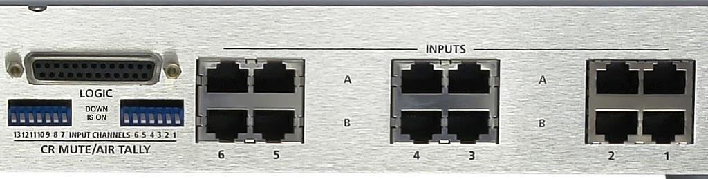
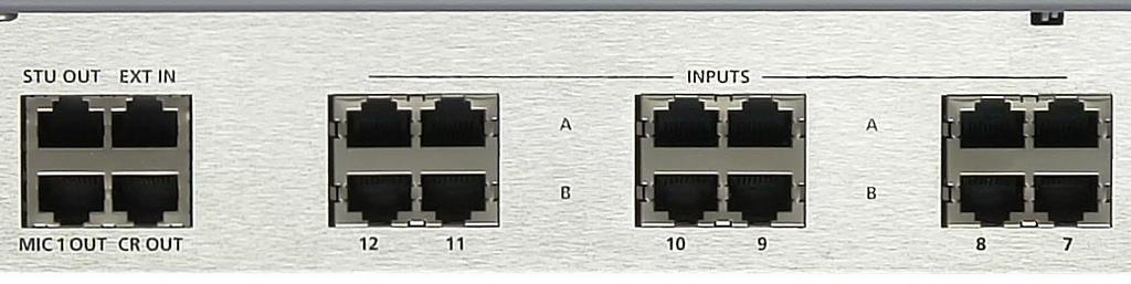
22 INSTAATION and POW Hook-Ups The rear of the console has multiple J-45 connectors to plug in 24 stereo line inputs, the external input, caller connections to and from hybrid, as well as providing studio, control room, microphone, PGM, and USB analog output connections. There is also a 6-pin plug terminal (CT7, on the CONA3-4 PCB) provided for microphone inputs. A DB-25 is provided for control connections and for the Cue output. There is also a USB port with type B connector available for interfacing with a computer (see page 2-4 for details). Pinouts drawings on pages 1-9 through 1-11 show all wiring connection at glance. Audio Connections Analog Stereo Inputs - J-45 (1 through 12) The signals are analog stereo; level is +4dBu balanced. A J-45 Pin 1 HI INPUT A T A J-45 Pin 2 O A J-45 Pin 3 HI INPUT A T A J-45 Pin 6 O B J-45 Pin 1 HI INPUT B T B J-45 Pin 2 O B J-45 Pin 3 HI INPUT B T B J-45 Pin 6 O MIC 1 and MIC 2 Inputs - 6-pin Plug Terminal All signals are analog mono. The mic input level is normally -50dBu balanced. Pin 1 MIC 1 In SH Pin 2 MIC 1 In O Pin 3 MIC 1 In HI Pin 4 MIC 2 In SH Pin 5 MIC 2 In O Pin 6 MIC 2 In HI MIC 1 and MIC 2 Outputs - J-45 All signals are analog mono, unbalanced. MIC 1 OUT J-45 Pin 1 HI MIC 1 OUT J-45 Pin 2 SH MIC 1 OUT J-45 Pin 3 HI MIC 1 OUT J-45 Pin 6 SH MIC 2 OUT J-45 Pin 1 HI MIC 2 OUT J-45 Pin 2 SH MIC 2 OUT J-45 Pin 3 HI MIC 2 OUT J-45 Pin 6 SH These connections are to the inputs of two internal mic preamplifiers. The outputs of the mic preamplifiers must be connected to the desired line inputs before you will be able to hear the microphones. See page 2-3 for details. page 22

23 INSTAATION and POW Caller Connections - J-45 The signals are analog mono; level is +4dBu balanced. CA IN J-45 Pin 1 HI CA IN J-45 Pin 2 O CA OUT J-45 Pin 1 HI CA OUT J-45 Pin 2 O PGM Outputs - J-45 The signals are analog stereo; level is +4dBu balanced. PGM 1 OUT J-45 Pin 1 HI PGM 1 T OUT PGM 1 OUT J-45 Pin 2 O PGM 1 OUT J-45 Pin 3 HI PGM 1 T OUT PGM 1 OUT J-45 Pin 6 O PGM 2 OUT J-45 Pin 1 HI PGM 2 T OUT PGM 2 OUT J-45 Pin 2 O PGM 2 OUT J-45 Pin 3 HI PGM 2 T OUT PGM 2 OUT J-45 Pin 6 O xternal Inputs - J-45 The signals are analog stereo; level is +4dBu balanced. XT IN J-45 Pin 1 HI XT T IN XT IN J-45 Pin 2 O XT IN J-45 Pin 3 HI XT T IN XT IN J-45 Pin 6 O Monitor Outputs - J-45 The signals are analog stereo; unbalanced. C OUT J-45 Pin 1 HI C T OUT C OUT J-45 Pin 2 SH C OUT J-45 Pin 3 HI C T OUT C OUT J-45 Pin 6 SH STU OUT J-45 Pin 1 HI STU T OUT STU OUT J-45 Pin 2 SH STU OUT J-45 Pin 3 HI STU T OUT STU OUT J-45 Pin 6 SH USB Output - J-45 The signals are analog stereo; level is +4dBu balanced. USB POT OUT J-45 Pin 1 HI USB T OUT USB POT OUT J-45 Pin 2 O USB POT OUT J-45 Pin 3 HI USB T OUT USB POT OUT J-45 Pin 6 O page 23


24 INSTAATION and POW Cue Output and Control Connections - DB-25 All control ports (except On Air Tally and Mic 2 TB to Cue/C) use opto-isolators. Functions include Mic 2 TB to Cue/C, On Air Tally, and Start for remote source machines. Several pins can be used for the common side connections to remote starts, as indicated on the pinout below. DB-25 Connections Pin 1 Start Channel 1 Pin 2 Start Channel 2 Pin 3 Start Channel 3 Pin 4 Start Channel 4 Pin 5 Start Channel 5 Pin 6 Start Channel 6 Pin 7 Cue Out Pin 8 Cue Out Audio Common Pin 9 On Air Tally N.O. Pin 10 On Air Tally Common Pin 11 Mic 2 TB to Cue/C Pin 12 Mic 2 TB to Cue/C Common Pin 13 Start Common Pin 14 Start Common Pin 15 Start Common Pin 16 Start Common Pin 17 Start Common Pin 18 Start Common Pin 19 Start Channel 7 Pin 20 Start Channel 8 Pin 21 Start Channel 9 Pin 22 Start Channel 10 Pin 23 Start Channel 11 Pin 24 Start Channel 12 Pin 25 Start Phone Channel Typical DB-25 connector Cue Output The Cue output signal (for feeding an external cue amplifier) is mono unbalanced. page 24
25 INSTAATION and POW To STAT emote Source Machines Using Channel STAT Switches XTNA STAT Hook up the remote machine s start control pins to the DB-25 connector control pins; for example, for channel 1 wire to Start Channel 1, Pin 1, and Start Common, either one of the Pins MIC 2 Talkback to Cue/Control oom The talkback to cue logic input is used to connect an external user-supplied button that enables the person activating it to talk to the operator in the control room, via the console s cue speaker. Provide a closure between Mic 2 TB to Cue/C, Pin 11 and Mic 2 TB to Cue/C Common, Pin 12. This will cause the channel s pre fader signal to be sent to the console s Cue bus, where it may be heard by the console operator. This nonlatching condition continues until the closure is released. (equires a user-supplied momentary action TAKBACK switch at the studio microphone location.) On Air Tally ets any programmed channel s STAT switch control an on-air light or other microphone on indicator at a remote location. This control function provides a contact closure between Pin 9 (On Air Tally N.O.) and Pin 10 (On Air Tally Common) whenever the module is ON. This signal can be used to control an externally powered tally light that requires a continuous closure to function. Current should not exceed 2 amps at 30 volts DC. page 25


26 AI 3 Console ear page 26
AIR 2 + RADIO CONSOLE
 AIR 2 + RADIO CONSOLE TECHNICAL MANUAL November 2006 AIR 2+ Radio Console Technical Manual - 1st Edition 2006 Audioarts Engineering* AUDIOARTS ENGINEERING 600 Industrial Drive New Bern, North Carolina
ANALOG RADIO MIXER. Flexible. Affordable. Built To Last.
 ANALOG RADIO MIXER Flexible. Affordable. Built To Last. Audioarts AIR-4 A N A L O G R A D I O M I X E R At Audioarts, value engineering is straightforward: Define the features our customers require. Design
A I R 5 RAdIo Console
 A I adio Console Technical Manual February 0 AI adio Console Technical Manual 0 Audioarts Engineering* AUDIOATS ENGINEEING 00 Industrial Drive New Bern, North Carolina --000 *a division of Wheatstone Corporation
S0 Radio Broadcasting Mixer. June catalogue. Manufacturers of audio & video products for radio & TV broadcasters
 S0 Radio Broadcasting Mixer June 2012 catalogue Manufacturers of audio & video products for radio & TV broadcasters S0 Radio Broadcasting Mixer A simple radio mixer for novice and professional users The
Output Board - v2* 4.1 Overview. 4.2 Audio Circuitry Program and Audition Outputs
 Output Board - v2* 4.1 Overview This circuit board provides the following console functions: Line output amplification Cue amplification Headphone amplification External Inputs (balanced *) Monitor sends
MODULAR I/O DIGITAL AUDIO CONSOLE. Flexible. Affordable. Built To Last.
 MODULAR I/O DIGITAL AUDIO CONSOLE Flexible. Affordable. Built To Last. 2 Audioarts X-12 Digital MODULAR I/O DIGITAL AUDIO CONSOLE There was a time when handling digital audio was an option. Not anymore.
S1 Digital/Analogue Radio Broadcast Mixer September 2009
 S1 Digital/Analogue Radio Broadcast Mixer September 2009 www.sonifex.co.uk t: +44 (0)1933 650 700 f: +44 (0)1933 650 726 sales@sonifex.co.uk S1 Radio Digital/Analogue Broadcast Mixer Radio Broadcast Mixer
S1 Digital/Analogue Radio Broadcast Mixer
 S1 Digital/Analogue Radio Broadcast Mixer September 2009 www.sonifex.co.uk t: +44 (0)1933 650 700 f: +44 (0)1933 650 726 sales@sonifex.co.uk S1 Radio Digital/Analogue Broadcast Mixer Radio Broadcast Mixer
PHASE HL SEL 1 HL SEL 2 EXT MONITOR ELAN ELAN ELAN ELAN MLM-201 HLM-201 HLM-201 TBM-201 MLM-201 GAIN GAIN GAIN LEFT GAIN RIGHT SELECT SELECT SELECT
 Audio Promotional Information "Kestrel-12" and "Kestrel-16" Modular Dual Channel Stereo "On-Air" Mixer "Kestrel-12" "KESTREL-12" HL SEL 1 HL SEL 2 EXT MITOR VU O'LOAD PHASE VU VU AUDIO AIR DELAY DUMP TLM-201
Features. Other system features. Up to 40 channels can be fitted
 With the relentless expansion of Broadcasting in all parts of the world, we have recognised the market s need for a more cost-effective, small format audio console which is not only well-featured, but
BSM Evolution USB - Compact ON AIR console. BSM Evolution USB. AEV On Air compact broadcast console
 BSM Evolution USB AEV On Air compact broadcast console 1 Guarantee The equipment is warranted for a period of 2 years from the date of invoice (ex-works). The warranty does not cover faults provoked by
MIDAS Venice Pin-Assignments Page 1 / 3 Mono-Channel-PCB Stereo- / Master - PCB CN 1 circuit diagram number CN 6 circuit diagram number CN
 MIDAS Venice Pin-Assignments Page 1 / 3 Mono-Channel-PCB 81346 Stereo- / Master - PCB 82230 CN 1 circuit diagram number CN 6 circuit diagram number CN 7 circuit diagram number CN 1 circuit diagram number
Radio for Everyone...
 Radio for Everyone... P R O D U C T I O N O N A I R C O N S O L E Eight dual inputs Built in auto Silence detector 4 USB in/out stereo channels Play out USB control section included AES 3 digital program
STUDIO Q User Guide. Radial Engineering Ltd Kebet Way, Port Coquitlam BC V3C 5M5 Tel: Fax:
 TM STUDIO Q User Guide 1588 Kebet Way, Port Coquitlam BC V3C 5M5 Tel: 604-942-1001 Fax: 604-942-1010 Email: info@radialeng.com Studio-Q Talk Back Interface Overview... 1 Features...2-3 Making Connections...4-5
3124mb+ All Discrete 4 Channel Mic/Instrument Preamplifier with Stereo Mixer Operator s Manual
 3124mb+ All Discrete 4 Channel Mic/Instrument Preamplifier with Stereo Mixer Operator s Manual Written by Carl J Houde 2015 Table of Contents 1.0 Introduction... 3 2.0 Overview... 4 2.1 3124mb+ Features
AEQ BRAVO Broadcast Mixing Console
 AEQ Broadcast Mixing Console USER S MANUAL ED 12/07 V 11-17/12/2007 CONTENTS 1 INTRODUCTION 3 11 General 3 12 Maintenance 3 13 Warranty 4 2 EQUIPMENT POWER SUPPLY 5 21 General 5 22 Switching on the equipment
AEQ BRAVO Broadcast Mixing Console
 AEQ Broadcast Mixing Console USER S MANUAL ED. 12/07 V. 1.5-20/05/2008 CONTENTS 1. INTRODUCTION... 3 1.1. General... 3 1.2. Maintenance... 3 1.3. Warranty... 4 2. EQUIPMENT POWER SUPPLY... 5 2.1. General...
OWNERS MANUAL LUNATEC V3 MICROPHONE PREAMPLIFIER AND A/D CONVERTER
 OWNERS MANUAL LUNATEC V3 MICROPHONE PREAMPLIFIER AND A/D CONVERTER LUNATEC 35 +48 35 +48 30 40 30 40 0 25 45 25 45 3 192 1 1 6 176.4 20 50 20 50 9 96 12 PEAK 88.2 55 55 RESET 48 10 60 2 10 60 2 21 44.1
GS-CU001M COMMENTATOR UNIT PRODUCT DETAILS
 GLENSOUND ELECTRONICS LTD GS-CU001M COMMENTATOR UNIT PRODUCT DETAILS 6 BROOKS PLACE, MAIDSTONE, KENT, ME1 1HE. ENGLAND. TEL: + (0) 1622 7020 Visit our Website at www.glensound.co.uk + (0) 1622 7662 FAX:
ARC-10 Advanced Radio Console family
 KIS advancedradio I C S P C S C-10 dvanced adio Console family C-10 unbalanced $1,599 msrp C-10P unbalanced w PC $1,999 msrp C-10BP balanced w PC $2,495 msrp C-16 16 in x 3 out switcher $995 msrp a very
FF DUAL FORMAT DJ MIXER USERS MANUAL
 FF - 4000 DUAL FORMAT DJ MIXER USERS MANUAL FF - 4000 INTRODUCTION The features and layout of the FF-4000 were determined in collaboration with leading loudspeaker manufacturers Funktion One, who canvassed
MIX-MINUS BRIDGE TABLE OF CONTENTS SECTION 1 ...INTRODUCTION YOU NEED MIX-MINUS FEATURES WHAT COMES WITH MMB...
 MIX-MINUS BRIDGE TABLE OF CONTENTS SECTION 1 SECTION 2 SECTION 3 SECTION 4 SECTION 5 TABLE LISTING FIGURE LISTING...INTRODUCTION... 3...YOU NEED MIX-MINUS... 3...FEATURES... 3...WHAT COMES WITH MMB...
SERIES 10 USER GUIDE
 SERIES 10 USER GUIDE Soundcraft Electronics Ltd. 1992, 1993 All rights reserved Parts of the design of this product may be protected by worldwide patents. Issue 2 Part No. ZM0004 Information in this manual
Model 60 Central Controller and Model 61 Control Console. User Guide
 Model 60 Central Controller and Model 61 Control Console User Guide Issue 2, March 1998 This User Guide is applicable for serial numbers: Model 60 00200 to 00300 Model 61 00151 and later 1998 by Studio
AirWave. Communication Module. Installation. Operations Manual PR&E Revision B 1/01
 & TM Communication Module Installation & Operations Manual PR&E 7-33 Revision B /0 Installation The Communication Module features 0 individual momentary buttons. The first 6 buttons (counting from the
+41 * 2 db. GENERAL The Shure M675 Broadcast Production Master is designed for use in conjunction with a Shure M67 or
 2 2 2 HARTREY AVE., EVANSTON, IL. 6 0 2 0 4 U.S.A. GENERAL The Shure M675 Broadcast Production Master is designed for use in conjunction with a Shure M67 or M67-2E Professional Microphone Mixer, M63 Audio
Introducing the New Daking Console
 Introducing the New Daking Console Daking The Console that can change from a Legacy Bussing scheme to DAW Direct Routing with the touch of a button. Features: Class A Circuitry Transformer Coupled Pre-Amps
XB-14 Quick Operation Manual V1 23/10/2013
 XB-14 Quick Operation Manual V1 23/10/2013 14. MIXER ON/OFF SWITCH 19. USB GAIN CONTROL 17. ST1 18. ST16 SELECTOR SELECTOR 7. GAIN CONTROL 6. 100Hz HIGH PASS FILTER 13. MAIN 16. GAIN 5. EQ METERS 12. PHANTOM
MX-206 Stereo Microphone Mixer. Operating Manual
 MX-206 Stereo Microphone Mixer Operating Manual ASHLY AUDIO INC. 847 Holt Road Webster, NY 14580-9103 Phone: (585) 872-0010 Toll-Free: (800) 828-6308 Fax: (585) 872-0739 www.ashly.com Operating Manual
Natural-sounding telephone audio... Hybrids
 Natural-sounding telephone audio... Hybrids ... for broadcast, conferencing and public address About Comrex DH Series Digital Telephone Hybrids When you want to present, broadcast, or record a telephone
D-76 DIGITAL AUDIO CONSOLE
 D-76 DIGITAL AUDIO CONSOLE Flexible. Affordable. Built To Last. 2 D-76 DIGITAL RADIO CONSOLE Audioarts consoles and control surfaces It s a good bet there s not a single person in America, who s listened
innkeeper LTD Digital Hybrid User Guide JK Audio
 innkeeper LTD Digital Hybrid User Guide JK Audio Introduction Innkeeper LTD allows you to send line level signals into the phone line while maintaining excellent separation between your voice and the caller.
Overview. A 16 channel frame is shown.
 Overview A 16 channel frame is shown. 22 Mono Input Channel 1 - MIC INPUT The mic input accepts XLR-type connectors and is designed to suit a wide range of BALANCED or UNBALANCED signals. Professional
EN Dateq BCS25 Manual Safety instructions 3. 1 All safety instructions, warnings and operating instructions must be read first.
 BCS25 USER MANUAL EN Dateq BCS25 Manual Safety instructions 3 Safety instructions 1 All safety instructions, warnings and operating instructions must be read first. 2 All warnings on the equipment must
Solid State Logic S O U N D V I S I O N
 Solid State Logic S O U N D V I S I O N SUPERANALOGUE X - R A C K Super-Analogue Outboard XR622 X-Rack Master Module User s Guide This documentation package contains the User s Guide for your new X-Rack
Summit Audio Model TLA-50 Tube Leveling Amplifier
 Summit Audio Model TLA-50 Tube Leveling Amplifier ATTACK FAST SLOW MEDIUM 3 4 5 6 7 TUBE LEVELER 40 60 80 100 VU 3 4 5 6 TLA-50 7 FAST SLOW RELEASE OUTPUT RED. METER 2 1 0 10 GAIN 9 8 7 5 3 1 0 1 2 +3
THE BOX 8 Recording & Mixing Console Operator s Manual
 Recording & Mixing Console Operator s Manual Written for Automated Processes Incorporated by Dan Pfeifer Rev. 19-1-15 2019 8301 Patuxent Range Road Jessup, MD 20794 USA 301-776-7879 http://www.apiaudio.com
LPFM LOW POWER FM EQUIPMENT GUIDE
 LPFM LOW POWER FM EQUIPMENT GUIDE BROADCAST AUDIO PERFECTIONISTS LPFM low power FM equipment guide One of the challenges in launching a new LPFM station is assembling a package of equipment that provides
clipping; yellow LED lights when limiting action occurs. Input Section Features
 ELX-1A Rack-Mount Mic/Line Mixer Four inputs, one output in a single rack space Very-highery-high-quality audio performance High reliability Extensive filtering circuitry and shielding protect against
1608-II and 2448 Recording Console Operator s Manual
 Recording Console Operator s Manual Written for Automated Processes ncorporated by Dan Pfeifer Rev. 18-12-30 2018 8301 Patuxent Range Road Jessup, MD 20794 USA 301-776-7879 http://www.apiaudio.com Table
Recording to Tape (Analogue or Digital)...10
...10") c o n t e n t s DUAL MIC-PRE Green Dual Mic Pre (introduction).............................4 Section (i): Setting Up Power Connections...........................................4 Power Supply................................................5
c o n t e n t s DUAL MIC-PRE Green Dual Mic Pre (introduction).............................4 Section (i): Setting Up Power Connections...........................................4 Power Supply................................................5
Model 6010 Four Channel 20-Bit Audio ADC Data Pack
 Model 6010 Four Channel 20-Bit Audio ADC Data Pack Revision 3.1 SW v1.0.0 This data pack provides detailed installation, configuration and operation information for the Model 6010 Four Channel 20-bit Audio
MANUAL DE INICIO RÁPIDO ESPAÑOL ( 7 10 ) GUIDE D UTILISATION RAPIDE FRANÇAIS ( ) MANUALE RAPIDO DI UTILIZZAZIONE ITALIANO ( )
 GUIDE D UTILISATION RAPIDE FRANÇAIS ( ) MANUALE RAPIDO DI UTILIZZAZIONE ITALIANO ( )") QUICKSTART GUIDE ENGLISH ( 6 ) MANUAL DE INICIO RÁPIDO ESPAÑOL ( ) GUIDE D UTILISATION RAPIDE FRANÇAIS ( 4 ) MANUALE RAPIDO DI UTILIZZAZIONE ITALIANO ( 5 ) KURZANLEITUNG DEUTSCH ( 22 ) INTRODUCTION Welcome
QUICKSTART GUIDE ENGLISH ( 6 ) MANUAL DE INICIO RÁPIDO ESPAÑOL ( ) GUIDE D UTILISATION RAPIDE FRANÇAIS ( 4 ) MANUALE RAPIDO DI UTILIZZAZIONE ITALIANO ( 5 ) KURZANLEITUNG DEUTSCH ( 22 ) INTRODUCTION Welcome
E-1 Digital Control Surface Technical Guide
 E-1 Digital Control Surface Technical Guide 600 Industrial Drive, New Bern, North Carolina, USA 28562 GENERAL INFORMATION General Information Introduction Evolution 1 is a new control surface that revolutionizes
TL AUDIO M4 TUBE CONSOLE
 TL AUDIO M4 TUBE CONSOLE USER MANUAL TL AUDIO M4 TUBE CONSOLE M4 INTRODUCTION... 3 M4 MIXER TECHNICAL SPECIFICATION... 4 Mic Input:... 4 Line Input:... 4 Phase Rev:... 4 High Pass Filter:... 4 Frequency
X-Four console. description. features. sound fundamentals. built to defy murphy s law. wide range of configurations
 X-Four console description If your application requires all the features and performance of a thoroughly-professional mixing console, but presents severe spacerestrictions, then the Crest Audio X-Four
Time For Change GS-HL-005. Single Unit Commentary. Key Points. Single Unit Commentary. Glensound. COIN GT-013 Glensound Commentary Telex Intercom
 Single Unit Commentary Time For Change commentary & intercom Single user commentary system High specification mic input with compressor 48v Phantom Power GS-HL-005 Three source Headphone Monitoring - Talk
Technical Instruction Manual
 Technical Instruction Manual DORROUGH STEREO SIGNAL TEST SET Model 0 STEREO SIGNAL TEST SET MODEL 0 -/ - -/- -0/ 0 / 0 - - - - -0 STEREO SUM/DIFF. -. - -0-6. - - -0 - - 0 - - - - 0 0 6 - - 0 0 0. -. -
AIRLAB. User Manual. Mixing consoles Version 2.03
 AIRLAB User Manual Mixing consoles Version 2.03 D&R ELECTRONICA WEESP BV Rijnkade 15B 1382 GS Weesp The Netherlands Phone: +31 (294) 418014 Fax: +31 (294) 416987 Website: http://www.d-r.nl E-mail: info@d-r.nl
DP1 DYNAMIC PROCESSOR MODULE OPERATING INSTRUCTIONS
 DP1 DYNAMIC PROCESSOR MODULE OPERATING INSTRUCTIONS and trouble-shooting guide LECTROSONICS, INC. Rio Rancho, NM INTRODUCTION The DP1 Dynamic Processor Module provides complete dynamic control of signals
Model 50 Central Controller, Model 51 Control Console, and Related Components. User Guide
 Model 50 Central Controller, Model 51 Control Console, and Related Components User Guide Issue 5, June 2002 This User Guide is applicable for systems consisting of: Model 50, serial number M50-00385 to
Onyx 1640i PREMIUM MIXER WITH FIREWIRE. FEATURES: 16-channel premium analog mixer with integrated 24-bit / 96 khz FireWire I/O APPLICATIONS
 Featuring a full mono mic/line channels each with -band dual sweep Perkins EQ, six aux sends each with pre/post and solo capability, four subgroups and a powerful master section, the is the flagship mixer
ARC-15. Broadcast Console family. Technical Manual May 22, 2017 ARRAKIS 1.0. Arrakis Systems ARC-15. advancedradio. Console. Mic. Phone.
 A D I O C O N S O E P O D U C T S AC-15 Broadcast Console family AC-15 Arrakis Systems inc. Advanced adio Console Talk Talk to Caller Monitor & Headphone put Select Head phone Air Arrakis Systems Monitor
Important Safety Instructions
 ) 2 1 @ A $ & 4 A? H @ E C + I A F A H = J H I = K = = F E4 Important Safety Instructions 1. Please read these instructions 2. Keep this Manual in a safe place 3. Do not use this console near water 4.
CHAPTER 3 AUDIO MIXER DIGITAL AUDIO PRODUCTION [IP3038PA]
![CHAPTER 3 AUDIO MIXER DIGITAL AUDIO PRODUCTION [IP3038PA]](/thumbs/73/68858919.jpg "CHAPTER 3 AUDIO MIXER DIGITAL AUDIO PRODUCTION [IP3038PA]") CHAPTER 3 AUDIO MIXER DIGITAL AUDIO PRODUCTION [IP3038PA] Learning Objectives By the end of this chapter, students should be able to: 1 State the function of the audio mixer in the sound studio. 2 Explain
CHAPTER 3 AUDIO MIXER DIGITAL AUDIO PRODUCTION [IP3038PA] Learning Objectives By the end of this chapter, students should be able to: 1 State the function of the audio mixer in the sound studio. 2 Explain
SRP-V200. Audio Mixer
 Audio Mixer SRPV00 The versatile Sony SRPV00. Six stereo inputs, four mono inputs, four mixing buses and a full range of operational features combined in a single, compact unit. Use the parallel control
The Dangerous Music D-Box user s operating guide
 The Dangerous Music D-Box user s operating guide Thank you for choosing products from the exciting line of Dangerous Music recording equipment. Many years of dependable and trouble-free service can be
Slate Control User Manual
 Slate Control User Manual This guide contains information on the expanded functions of the SLATE CONTROL, diagrams of connections and basic functions, and some example setups. Overview The Slate Control
February 2019 Factory Pricing with Product Specifications
 February 2019 Factory Pricing with Product Specifications 2 MILLENIUM HYBRID CONSOLES Millenium Hybrid Console (Model RS-18HRJ shown) Features: Full metering with programmable LED peak indicators 8 position
T L Audio. User Manual C1 VALVE COMPRESSOR. Tony Larking Professional Sales Limited, Letchworth, England.
 T L Audio User Manual C1 VALVE COMPRESSOR Tony Larking Professional Sales Limited, Letchworth, England. Tel: 01462 490600. International +44 1462 490600. Fax: 01462 490700. International +44 1462 490700.
Installation and Operation Manual
 PROBLEM SOLVED Installation and Operation Manual INC ProMix-1 Single Channel Remote/Podcast Audio Interface. Manual update 04/23/18 If you need a firmware upgrade, contact Broadcast Tools No part of this
ARC-8. Radio Console. Technical Manual ARRAKIS 1.0. May 22, 2017
 A D I O C O N S O E P O D U C T S AC-8 adio Console Technical Manual May 22, 2017 AAKIS advancedradio 1.0 I N T O D U C T I O N Thank you from Arrakis Systems inc. Thank you for purchasing this product
AxumVideo 0 intro. Now that you have connected the different AXUM system parts, you are ready to configure the system according to your own needs.
 AxumVideo 0 intro Now that you have connected the different AXUM system parts, you are ready to configure the system according to your own needs. On the left we see the RACK unit and on the right we see
QUICKSTART GUIDE ENGLISH ( 1 4 ) GUÍA DE INICIO RÁPIDO ESPAÑOL ( 5 8 ) GUIDE D UTILISATION SIMPLIFIÉ FRANÇAIS ( 9 12 )
 GUÍA DE INICIO RÁPIDO ESPAÑOL ( 5 8 ) GUIDE D UTILISATION SIMPLIFIÉ FRANÇAIS ( 9 12 )") PROFESSIONAL 3-CHANNEL SCRATCH MIXER QUICKSTART GUIDE ENGLISH ( 1 4 ) GUÍA DE INICIO RÁPIDO ESPAÑOL ( 5 8 ) GUIDE D UTILISATION SIMPLIFIÉ FRANÇAIS ( 9 12 ) GUIDA RAPIDA ITALIANO ( 13 16 ) KURZANLEITUNG
PROFESSIONAL 3-CHANNEL SCRATCH MIXER QUICKSTART GUIDE ENGLISH ( 1 4 ) GUÍA DE INICIO RÁPIDO ESPAÑOL ( 5 8 ) GUIDE D UTILISATION SIMPLIFIÉ FRANÇAIS ( 9 12 ) GUIDA RAPIDA ITALIANO ( 13 16 ) KURZANLEITUNG
12 Channel Media Splitter MS12 Mk2 User manual
 12 Channel Media Splitter MS12 Mk2 User manual 01. 12 Channel Media Splitter MS12 Mk2 An audio distribution amplifier primarily designed to feed multiple ENG cameras from a single lectern microphone at
Master Section
 Master Section -18 9 9 18 VU VU The Master section of the Custom Series 75 is host to two linkable (and externally patchable) mono 2254 compressors, the 281 Channel Module routing options, eight Groups,
USER GUIDE. DM Engineering Multi Station Relay Adapter (MSRA and MSRA-RM) Version DM Engineering
 Version DM Engineering") USER GUIDE DM Engineering Multi Station Relay Adapter (MSRA and MSRA-RM) Version 1.35 DM Engineering 2174 Chandler St. Camarillo, CA 91345-4611 805-987-7881 800-249-0487 www.dmengineering.com Overview:
USER GUIDE DM Engineering Multi Station Relay Adapter (MSRA and MSRA-RM) Version 1.35 DM Engineering 2174 Chandler St. Camarillo, CA 91345-4611 805-987-7881 800-249-0487 www.dmengineering.com Overview:
AIRLAB DT. User Manual. Version Airlab-DT manual Page 1
 AIRLAB DT User Manual Version 1.07 D&R ELECTRONICA BV Rijnkade 15B 1382 GS Weesp The Netherlands Phone: +31 (294) 418014 Fax: +31 (294) 416987 Website: http://www.d-r.nl E-mail: info@d-r.nl Airlab-DT manual
AIRMATE-USB MANUAL V 2.07
 AIRMATE-USB MANUAL V 2.07 Dear Client, Thank you for choosing the D&R AIRMATE-USB mixer. The AIRMATE-USB was designed by Radio Broadcast professionals along with the D&R design team and is intended to
Recording & Mixing Console Operator s Manual
 Recording & Mixing Console 11-12-13 Written for Automated Processes Incorporated by Dan Pfeifer 2013 1 Table of Contents 1.0 Overview 2.0 Input Channels 1-4 2.1 Preamp 2.2 Filter, Routing, and Meter 2.2.1
SONOSAX SX-PR OPERATOR'S MANUAL
 SONOSAX SX-PR OPERATOR'S MANUAL Manual copyright 1989 - Gary J. Louie Sonosax is a trademark of Jacques Sax Edition 2.1 OVERVIEW The Sonosax SX-PR series portable stereo audio mixers are designed for jobs
J R Sky, Inc. tel: fax:
 STEREO OPTICAL RECORDING SYSTEM N UOPTIX STEREO OPTICAL RECORDING MONITOR LEFT SYSTEM MODE PREVIEW RECORD BIAS RECORD REV SETUP TEST RIGHT INPUT SETUP INPUT BIAS SETUP BIAS INPUT STEREO AUX MONO DIRECT
MODEL PA-2 AUDIOPATH ENHANCHER (1998-MSRP $399.00)
") F O R T H E L O V E O F M U S I C MODEL PA-2 AUDIOPATH ENHANCHER (1998-MSRP $399.00) OPERATION INSTALLATION MANUAL INTRODUCTION After countless hours of analyzing the performance of existing car audio
F O R T H E L O V E O F M U S I C MODEL PA-2 AUDIOPATH ENHANCHER (1998-MSRP $399.00) OPERATION INSTALLATION MANUAL INTRODUCTION After countless hours of analyzing the performance of existing car audio
CXM Mixer Installation & User Guide
 CXM Mixer Installation & User Guide Cloud Electronics Limited 140 Staniforth Road, Sheffield, S9 3HF England Tel +44 (0)114 244 7051 Fax +44 (0)114 242 5462 e-mail info@cloud.co.uk web site http://www.cloud.co.uk
AES Channel Digital/Analog Audio Switcher/DA/Digital to Analog Converter
 Broadcast Devices, Inc. AES-408 8 Channel Digital/Analog Audio Switcher/DA/Digital to Analog Converter Technical Reference Manual Broadcast Devices, Inc. Tel. (914) 737-5032 Fax. (914) 736-6916 World Wide
MX 3BT NF TK MAIN 2TK 2TK BT
 MX.3BT MX 3BT BT MAIN NF03852-1.1 The mains plug or an appliance coupler is used as the disconnect device, the disconnect device shall remain readily operable. 1. INTRODUCTION...4 2. FEATURES...4 3. INSTRUCTION...4
Instruction Manual. Series 3000 Model R-165A. Audio/Video IF/RF Relay Panel. CATV Switching and Control
 Series 3000 Model R-165A Audio/Video IF/RF Relay Panel Instruction Manual CATV Switching and Control 585-765-2254 fax 585-765-9330 100 Housel Ave. Lyndonville NY 14098 www.monroe-electronics.com Table
AM-4 Audio Monitor. Videoquip Research Limited 595 Middlefield Road, Unit #4 Scarborough, Ontario, Canada. MIV 3S2
 AM-4 Audio Monitor Videoquip Research Limited 595 Middlefield Road, Unit #4 Scarborough, Ontario, Canada. MIV 3S2 (416) 293-1042 1-888-293-1071 www.videoquip.com AM-4 4 channel Analog, AES3 Digital, SDI
Operating Manual. A 2554 Club DJ Audio Mixer
 www.altronics.com.au A 2554 Club DJ Audio Mixer edback Distributed by Altronic Distributors Pty. td. Phone: 1300 780 999 Fax: 1300 790 999 Internet: www.altronics.com.au IMPOTANT NOTE Please read these
CMX-DSP Compact Mixers
 CMX-DSP Compact Mixers CMX4-DSP, CMX8-DSP, CMX12-DSP Introduction Thank you for choosing a Pulse CMX-DSP series mixer. This product has been designed to offer reliable, high quality mixing for stage and/or
ENGLISH. Technical Specifications. Version 1.1 May 2000 EURODESK MX8000A.
 EURODESK MX8000A Technical Specifications Version 1.1 May 2000 www.behringer.com ENGLISH MX8000A Professional 48/24 channel inline mixing console s Additional 24 input Mix-B channels, all with individual
CM SERIES. 8 Channel Monitor / Crossover. 181 Bonetti Drive San Luis Obispo, CA ph: fax:
 CM SERIES 8 Channel Monitor / Crossover 181 Bonetti Drive San Luis Obispo, CA 93401 ph: 805-549-0161 fax: 805-549-0163 e-mail:usl@uslinc.com One Year Limited Warranty USL, Inc. warrants that each product
MASELEC MTC-6 SURROUND master transfer and monitor system
 MASELEC MTC-6 SURROUND master transfer and monitor system http://www.maselec.com/ Mases Electronics Ltd. Bishopswood, Cannon Hill Close, Bray, Berks SL6 2DH, England. Tel/Fax: +44 (0) 1628-770 104. E-mail:
LavryBlack Series Model DA10 Digital to Analog Converter
 LavryBlack Series Model DA10 Digital to Analog Converter Lavry Engineering, Inc. P.O. Box 4602 Rolling Bay, WA 98061 http://lavryengineering.com email: techsupport@lavryengineering.com January 14, 2008
MIXING CONSOLE. Owner s Manual. Keep This Manual For Future Reference.
 MIXING CSOE Owner s Manual Keep This Manual For Future eference. E i Precautions. Avoid excessive heat, humidity, dust and vibration Keep the unit away from locations where it is likely to be exposed to
AMU2-2MHD+ Audio monitoring Unit
 AMU2-2MHD+ Audio monitoring Unit Handbook TSL Vanwall Road, Maidenhead, Berkshire, SL6 4UB Telephone +44 (0)1628 676200, FAX +44 (0)1628 676299 AMU2-2MHD+-6 1 ISSUE 5 SAFETY Installation. Unless otherwise
The Dangerous 2-Bus Manual
 The Dangerous 2-Bus Manual Thank you for choosing products from the exciting line of Dangerous recording equipment. Many years of dependable and trouble-free performance can be expected from our gear.
M A S T E R S E C T I O N. User Manual
 M A S T E R S E C T I O N User Manual Version 1.02: July 2007 Contents. Safety Information.... 3 Welcome.... 4 Connections.... 5 A Basic Set-up 5 Setting Up.... 7 Adjusting Input Levels 7 Taking Account
ProFire 610. English. User Guide
 English User Guide User Guide Introduction............................................................ 3 What s in the Box........................................................ 3 Your ProFire 610 package
DLM471S-5.1 MULTICHANNEL AUDIO LEVEL MASTER OPERATION MANUAL IB B. (Mounted in RMS400 Rack Mount & Power Supply) (One of 4 Typical Cards)
 (One of 4 Typical Cards)") DLM471S-5.1 (Mounted in RMS400 Rack Mount & Power Supply) MULTICHANNEL AUDIO LEVEL MASTER (One of 4 Typical Cards) OPERATION MANUAL IB6432-02B TABLE OF CONTENTS PAGE 1.0 GENERAL DESCRIPTION 2 2.0 INSTALLATION
DLM471S-5.1 (Mounted in RMS400 Rack Mount & Power Supply) MULTICHANNEL AUDIO LEVEL MASTER (One of 4 Typical Cards) OPERATION MANUAL IB6432-02B TABLE OF CONTENTS PAGE 1.0 GENERAL DESCRIPTION 2 2.0 INSTALLATION
DH400. Digital Phone Hybrid. The most advanced Digital Hybrid with DSP echo canceller and VQR technology.
 Digital Phone Hybrid DH400 The most advanced Digital Hybrid with DSP echo canceller and VQR technology. The culmination of 40 years of experience in manufacturing at Solidyne, broadcasting phone hybrids,
COHERENCE ONE PREAMPLIFIER
 COHERENCE ONE PREAMPLIFIER OWNER S MANUAL TABLE OF CONTENTS Introduction Features Unpacking Instructions Installation Phono Cartridge Loading Basic Troubleshooting Technical Specifications Introduction
SYNERGY MINI DIGITAL BROADCAST CENTRE
 SYNERGY MINI DIGITAL BROADCAST CENTRE SYNERGY MINI is more than just a radio mixer. Much more. SYNERGY MINI is a multifunction digital broadcast centre allowing you to record, produce and broadcast both
USB Phono Plus. Project Series USER S MANUAL. Audiophile Computer Interface
 USB Phono Plus Audiophile Computer Interface Project Series USER S MANUAL IMPORTANT SAFETY INSTRUCTION READ FIRST This symbol, whenever it appears, alerts you to the presence of uninsulated dangerous voltage
CDM10: Channel USB Mixer. Item ref: UK User Manual
 CDM10:4 19 4 Channel USB Mixer Item ref: 171.135UK User Manual Caution: Please read this manual carefully before operating Damage caused by misuse is not covered by the warranty Introduction Thank you
ARC-10. Broadcast Console family. Pgm. Pgm. Pgm. Pgm. Pgm. Pgm. Aud. Aud. Aud. Aud. Aud. Aud. Cue. Cue. Cue. Cue. Cue. Cue.
 Arrakis Systems inc. R A D I O C O N S O L E P R O D U C T S ARC-10 Broadcast Console family ARC-10 Advanced Radio Console Talk Talk Talk to Caller Monitor & Headphone put Select Head phone Air Arrakis
Neve :2 Summing Mixer User Manual
 Neve 8816 16:2 Summing Mixer User Manual 527-361 Issue 5 AMS NEVE Billington Road Burnley Lancs BB11 5UB England Phone +44 (0)1282 457011 Fax: +44 (0)1282 417282 info@ams-neve.com www.ams-neve.com www.neve.eu
CL1200 MIXING CONSOLE. Item ref: UK User Manual
 CL1200 MIXING CONSOLE Item ref: 170.881UK User Manual Caution: Please read this manual carefully before operating Damage caused by misuse is not covered by the warranty Introduction Thank you for choosing
PROFESSIONAL 2-CHANNEL MIXER WITH EFFECTS LOOP
 PROFESSIONAL 2-CHANNEL MIXER WITH EFFECTS LOOP QUICKSTART GUIDE ENGLISH ( 1 4 ) GUÍA DE INICIO RÁPIDO ESPAÑOL ( 5 8 ) GUIDE D UTILISATION SIMPLIFIÉ FRANÇAIS ( 9 12 ) GUIDA RAPIDA ITALIANO ( 13 16 ) KURZANLEITUNG
CFX 12 (12X4X1) 8 mic/line channels, 2 stereo line channels. CFX 16 (16X4X1) 12 mic/line channels, 2 stereo line channels
 8 mic/line channels, 2 stereo line channels. CFX 16 (16X4X1) 12 mic/line channels, 2 stereo line channels") COMPACT CFX MIXERS COMPACT SOUND REINFORCEMENT MIXERS WITH EFX FOR THE GIGGING MUSICIAN THREE MODELS CFX 12 (12X4X1) 8 mic/line channels, 2 stereo line channels CFX 16 (16X4X1) 12 mic/line channels, 2
COMPACT CFX MIXERS COMPACT SOUND REINFORCEMENT MIXERS WITH EFX FOR THE GIGGING MUSICIAN THREE MODELS CFX 12 (12X4X1) 8 mic/line channels, 2 stereo line channels CFX 16 (16X4X1) 12 mic/line channels, 2