Cat. No. N093-E1-1A. K3NR Frequency/Rate Meter
|
|
|
- Stewart Holland
- 5 years ago
- Views:
Transcription
1 Cat. No. N093-E1-1A K3NR Frequency/Rate Meter
2 K3NR Frequency/Rate Meter Operation Manual Revised February 2001
3 iv
4 Notice: OMRON products are manufactured for use according to proper procedures by a qualified operator and only for the purposes described in this manual. The following conventions are used to indicate and classify precautions in this manual. Always heed the information provided with them. Failure to heed precautions can result in injury to people or damage to the product.! DANGER Indicates information that, if not heeded, is likely to result in loss of life or serious injury.! WARNING Indicates information that, if not heeded, could possibly result in loss of life or serious injury.! Caution Indicates information that, if not heeded, could result in relatively serious or minor injury, damage to the product, or faulty operation. OMRON Product References All OMRON products are capitalized in this manual. The word Unit is also capitalized when it refers to an OMRON product, regardless of whether or not it appears in the proper name of the product. The abbreviation Ch, which appears in some displays and on some OMRON products, often means word and is abbreviated Wd in documentation in this sense. The abbreviation PC means Programmable Controller and is not used as an abbreviation for anything else. Visual Aids The following headings appear in the left column of the manual to help you locate different types of information. Note Indicates information of particular interest for efficient and convenient operation of the product. 1, 2, Indicates lists of one sort or another, such as procedures, checklists, etc. OMRON, 1998 All rights reserved. No part of this publication may be reproduced, stored in a retrieval system, or transmitted, in any form, or by any means, mechanical, electronic, photocopying, recording, or otherwise, without the prior written permission of OMRON. No patent liability is assumed with respect to the use of the information contained herein. Moreover, because OMRON is constantly striving to improve its high-quality products, the information contained in this manual is subject to change without notice. Every precaution has been taken in the preparation of this manual. Nevertheless, OMRON assumes no responsibility for errors or omissions. Neither is any liability assumed for damages resulting from the use of the information contained in this publication. v
5 vi
6 TABLE OF CONTENTS PRECAUTIONS xi 1 General Precautions xii 2 Safety Precautions xii 3 Application Precautions xii 4 Noise Prevention xiii SECTION 1 Introduction Features Front of the Meter Rear of the Meter Modes Communications Function SECTION 2 Setup Mounting Input Block Output Board SECTION 3 Operating Modes Rotational/Circumferential Speed: F Absolute Ratio: F Error Ratio: F Rotational Difference: F Flow Rate Ratio: F Passing Time: F Pulse Counting: F SECTION 4 Parameter Setting Overview Setting Mode Protect Mode SECTION 5 Operations in RUN Mode Displaying and Changing Setting Values Displaying and Resetting of Maximum and Minimum Values (Operating Modes F1 to F6) External Input Signals SECTION 6 Useful Functions Teaching Function Output Test Maintenance Mode vii
7 TABLE OF CONTENTS SECTION 7 BCD Output Connectors Timing Charts SECTION 8 Troubleshooting Items to Be Checked First Display Appendices A Specifications B Estimated Frequency Calculation C List of Settings D Available Models E Available Parameters F Setting Examples Index Revision History viii
8 About this Manual: This manual describes the installation and operation of the K3NR Frequency/Rate Meter and includes the sections described below. Please read this manual carefully and be sure you understand the information provided before attempting to install and operate the K3NR. Section 1 describes the functions of the K3NR. The main components are also described. Section 2 provides instructions required for mounting and wiring the K3NR. Section 3 provides instructions for setting the parameters of the K3NR. Section 4 provides instructions for operating the K3NR in RUN mode. Section 5 provides information on the teaching function, output test, and maintenance mode. Section 6 provides information on the use of the K3NR with the BCD Output Board. Section 7 provides information for troubleshooting the K3NR The Appendices provide specifications, a list of settings, a list of standard models, and a list of available menu items.! WARNING Failure to read and understand the information provided in this manual may result in personal injury or death, damage to the product, or product failure. Please read each section in its entirety and be sure you understand the information provided in the section and related sections before attempting any of the procedures or operations given. ix
9 PRECAUTIONS This section provides precautions for using the K3NR Frequency/Rate Meter and related devices. The information contained in this section is important for the safe and reliable application of the K3NR. You must read this section and understand the information contained before attempting to set up or operate the K3NR. 1 General Precautions xii 2 Safety Precautions xii 3 Application Precautions xii 4 Noise Prevention xiii xi
10 Application Precautions Section 3 1 General Precautions 2 Safety Precautions The user must operate the product according to the performance specifications described in the operation manuals. Before using the product under conditions which are not described in the manual or applying the product to nuclear control systems, railroad systems, aviation systems, vehicles, combustion systems, medical equipment, amusement machines, safety equipment, and other systems, machines, and equipment that may have a serious influence on lives and property if used improperly, consult your OMRON representative. Be sure to read this manual before attempting to use the product and keep this manual close at hand for reference during operation.! WARNING Never attempt to disassemble any Units while power is being supplied. Doing so may result in serious electrical shock or electrocution.! WARNING Never touch any of the terminals while power is being supplied. Doing so may result in serious electrical shock or electrocution. 3 Application Precautions Observe the following precautions when using the product. Always use the power supply voltage specified in the specifications. Do not use the product in locations subject to flammable gases or combustible objects. Be sure to confirm terminal names when wiring. Be sure to tighten the screws on the terminal blocks. Observe the following precautions when mounting the product. Mount the product on level surfaces. Mount the product on a panel which has a thickness of 1 to 3.2 mm. Do not mount the product in the following places. Locations subject to strong shock or vibration. Locations subject to temperature or humidity exceeding the rated levels or where icing is liable to occur. Locations subject to dust. Locations subject to corrosive gases (particularly sulfuric gases or ammonium gases). Locations subject to direct sunlight or outdoor conditions. Locations near devices (high-frequency welders or high-frequency sewing machines) that produce high-frequency noise. xii
11 Noise Prevention Section 4 4 Noise Prevention Provide the following countermeasures when using the product in an environment where the product is exposed to noise. Countermeasures for protecting the product against high-frequency noise or abnormal voltages. Line filter Power input Frequency/Rate Meter + Signal input Frequency/Rate Meter Power input Countermeasures for protecting the product against inductive noise produced from the input line. + Frequency/Rate Meter 2-conductor shield wire xiii
12 SECTION 1 Introduction This section describes the functions of the K3NR. The main components are also described. Refer to the remaining sections of this manual for the operation of the K3NR and its menus in detail. 1-1 Features Front of the Meter Rear of the Meter Modes Communications Function
13 Features Section Features The K3NR Frequency/Rate Meter displays desired values after converting input pulses. The K3NR has the following functions. Operating mode Function 1 Displays rotational or circumferential speed of a single input. 2 to 5 Displays the calculation results of two rotational inputs. 6 Displays passing time calculated from the frequency and process length of a single input. 7 Counts and displays the number of pulses. Measurement The internal system clock counts the ON/OFF time (T) of sensor input or other input and automatically calculates the frequency. The number of revolutions is calculated from the result of the frequency multiplied by 60. Sensor input pulse ON/OFF time (T) = Frequency (f) = T 1 Prescaling Rotational speed (rpm) = f x 60 Circumferential speed = Circumference x revolutions Passing time = Length of processing/circumferential speed Pulse counting If there is any pulse input, the input will be automatically converted numerically and displayed. The number of input pulses is converted into a desired value. Enables the K3NR to display the revolutions or rotational speed. It is necessary to multiply the number of pulses per revolution or circumference by a certain factor. This factor is called the prescaling value. Example: Proximity Sensor K3NR rpm = f x 60 x a f: Input pulse frequency (number of pulses per second) a: Prescale value If there are five pulses per rotation, the accurate rotational speed can be calculated if a = 1/5 ( 0.2=2 x 10 1 ). Comparative Output Selection Linear Output BCD Output Communications Output HOLD Comparison output patterns can be selected from the standard, level, or zone output depending on the application. Refer to Comparative Output Patterns, page 80. Refer to Linear Output Range, page 83. A digital data output format where every four binary bits is numerically equivalent to one decimal digit. Refer to Section 7 BCD Output. Refer to the Communications Manual. HOLD is an external input which is used to stop the A/D process and freeze the display. The comparative, linear, and BCD outputs are also retained. Refer to 5-3 External Input Signals for details. 2
14 Features Section 1-1 RESET Teaching Output Test Hysteresis Startup Compensation Time Remote/Local Selection Process Time for Averaging Measured Value Auto-Zero Time RESET is an external input to reset the present max./min. values and counting values. The process value when the RESET is ON is set as the maximum and minimum values. The counting value is reset to zero. The max./min. values and counting values can be reset using the front panel keys. Refer to pages 104 and 105. The K3NR is provided with a teaching function that can set an actual measured value as a setting value without key input. This function is useful for setting parameters while checking the operating status of the K3NR. The teaching function can be used to set the set and prescaling values. It can be also used to set the linear output range of the K3NR with a Linear Output Board. Refer to 6-1 Teaching Function for details. This function is convenient for checking a system to which the K3NR is connected, especially when some inputs cannot be operated. The K3NR simulates an input to check the output conditions. Refer to 6-2 Output test for details. The established setting value includes a hysteresis setting to prevent chattering of the output when the measured value fluctuates in the vicinity of the setting values. Hysteresis is enabled when the measured value is starts to become smaller than the HH and H setting values and larger than the LL and L setting values. Refer to Hysteresis, page 78. The startup compensation time parameter keeps the measurement operation from sending an unnecessary output corresponding to instantaneous, fluctuating input from the moment the K3NR is turned ON until the end of the preset period. Refer to Startup Compensation Time, page 74. The K3NR can be operated remotely through a host computer or locally with key inputs. Remote Mode: For programming remotely by downloading setup parameters from a host computer via RS-232C, RS-485, or RS-422. Local Mode: Programming is performed with the front panel key input. Refer to Remote/Local Programming, page 86. Setting process time for averaging measured value prevents the display from fluctuating due to unstable input. Refer to Process Time for Averaging Measured Value, page 72. The input pulse frequency does not drop to zero perfectly due to the estimated frequency calculation of the K3NR. Therefore, the K3NR has a function to calibrate the frequency to zero forcibly should no input pulse be received for a certain period. The period during which no pulse is received before the K3TR sets the frequency to zero is called auto-zero time. Refer to page 62. 3
15 Front of the Meter Section Front of the Meter Comparative output status indicators PV display Status indicators Teaching indicator Unit of measure SV display status indicators SV display Escape Key Up Key RESET/TEACH Key Mode Key Shift Key Five-digit ( to 99999), seven-segment, 14.2-mm-high LED display with a programmable decimal point. The displays show the process value, maximum value, minimum value, operations/parameters when setting, and error messages. PV Display K3NR- A RUN Mode: Displays the process, maximum, and minimum values. Also displays setting values while the SV indicator is lit. When changing a value, all digits other than those that can be set become dimmer. Setting Mode: Displays the menu, parameter, or setting value. When changing a value, all digits other than those that can be set become dimmer. K3NR- C RUN Mode: Displays the process, maximum, and minimum values. Setting Mode: Displays the menu and parameters. SV Display (Setting value LED Display Models Only) RUN Mode: Setting Mode: Displays comparative set values. When changing a value, all digits other than those that can be set become dimmer. Displays setting values. When changing a value, all digits other than those that can be set become dimmer. Comparative Output Status Indicators Indicates the status of the comparative output. 4
16 Front of the Meter Section 1-2 Status Indicators Teaching Indicator SV Display Status Indicators Unit of Measure Escape Key HOLD Indicator Lit when the HOLD input signal is ON. MAX Indicator Lit when the value displayed on the PV display is the maximum value. MIN Indicator Lit when the value displayed on the PV display is the minimum value. PROG Indicator Lit when the setting mode menu is displayed. The indicator flashes while parameters are displayed. Lit when displayed parameters can be set in teaching operation. The indicator flashes when the process value is indicated as a setting value. Indicates which set value is on the PV or SV display. Attach the appropriate label showing the unit of measure (enclosed). Used to select the process, maximum, or minimum value to be displayed on the PV display in RUN mode. ESC ESC Process value Maximum value Minimum value Used to return from the setting, protect, or maintenance mode to the RUN mode. This key is also used to return to the previous operation during the setting, protect, or maintenance mode. Mode Key Displays a setting value (out of HH, H, L, and LL setting values in this order) on the PV display in RUN mode when this key is pressed. Unless another operation key is pressed within five seconds after this key has been pressed, the display automatically changes to the one for process values. Process value Maximum value Minimum value HH is lit. HH setting value No key input for 5 seconds. H is lit. L is lit. LL is lit. H setting value No key input for 5 seconds. L setting value No key input for 5 seconds. LL setting value No key input for 5 seconds. In the RUN mode, this button terminates the measurement process and allows you to enter the setting mode, advancing through the menus and parameters. Menu 1 Menu 2 Menu n Parameter 1 Parameter 2 Parameter n In the setting mode, this button will store changes in the non-volatile memory while at the same time advancing the display to the next menu item. 5
17 Front of the Meter Section 1-2 Up Key Used to select a parameter to be displayed for setting value change. Used to increment the current digit in the setting value by one. The value increases in the following order: 0, 1, 2, 3, 4, 5, 6, 7, 8, 9, ( 1), and ( ) Only the leftmost digit will be displayed if the value is set to 1 or. The value will be set to 0 if this key is pressed when 9 or is displayed. Shift Key Used to change the parameter displayed in setting mode. Used to scroll the digit to the right of the presently displayed digit. RESET/TEACH Key Used to reset the maximum value, minimum value, or counting value in RUN mode. Used to select the teaching function. Refer to 6-1 Teaching Function for details. 6
18 Rear of the Meter Section Rear of the Meter Terminal arrangement varies depending on the selected Output Board. For wiring, refer to Section 2 Setup. K3NR with Relay Output Board, K31-C1, -C2, -C5 K3NR with Transistor Output Board, K31-T1, -T2 K3NR with Linear Output Board, K31-L1, -L2, -L3, -L4, -L5, -L6, -L7, -L8, -L9, -L10 K3NR with RS-485 Output Board, K31-FLK2, -FLK5 Output Board Input Board K3NR with BCD Output Board, K31-B2, -B4 Output Board Input Board K3NR with RS-232C Output Board, K31-FLK1 Communications Output Board Input Board 7
19 Modes Section 1-4 K3NR with RS-422 Output Board, K31-FLK3 Communications Output Board Terminator Input Board K3NR with RS232C + Transistor Output Board, K31-FLK4 K3NR with RS Transistor Output Board, K31-FLK6 Communications Output Board Transistor Output Board Terminator Input Board 1-4 Modes The following four modes are available. RUN mode for normal operations (see Section 5 Operations in RUN Mode) Setting mode for initializing parameter input (see Section 4 Parameter Setting) Protect mode for lock-out configuration (see 4-1 Protect Mode) Maintenance mode for initialization (see Initialization) Refer to the following for the relationship among these modes and selection of the modes. Press the Mode and Shift Keys while turning on the K3NR. Power on Maintenance mode Press the Escape and up Keys for 1 second. RUN mode RUN mode Protect mode 1 second Setting mode RUN Mode K3NR is in RUN when the K3NR is turned ON. The K3NR in this mode provides an output signal as a result of the comparison of the measured and setting values. 8
20 Communications Function Section 1-5 The basic model in this mode usually displays the process value. The maximum and minimum values are displayed by pressing the Escape Key. The parameters and setting values are displayed by pressing the Mode Key. Refer to Section 5 Operations in RUN Mode for RUN mode in detail. Setting Mode Protect Mode Values are set in the K3NR in this mode by key input or using the teaching function. Refer to Section 4 Parameter Setting for value setting by key input and 6-1 Teaching Function for the teaching function in detail. Use this mode to prohibit some operations in order to lock out the setting values. Refer to 4-1 Protect Mode for details. Maintenance Mode The setting values are reset to factory-set values in this mode. Refer to Initialization for details. 1-5 Communications Function The communications function of the K3NR makes it possible for the host computer to perform the following operations. Confirmation and change of setting values. Communications conditions cannot be changed. Reading and resetting the maximum and minimum values. Confirmation of model data. Use a model with the Communications Board if the communications function is required. Refer to the Communications Manual for the communications function in detail. RS-232C RS-422 RS-485 Use the K31-FLK1 or K31-FLK4 Output Board to use the RS-232C interface. Use the K31-FLK3 or K31-FLK6 Output Board to use the RS-422 interface. Use the K31-FLK2 or K31-FLK5 Output Board to use the RS-485 interface. 9
21 SECTION 2 Setup This section provides instructions required for mounting and wiring the K3NR. 2-1 Mounting Input Block Terminal Arrangement Wiring Precautions Wiring Output Board Terminal Arrangement Relay Output Board Transistor and Combination Output Board Linear Output Board BCD Output Board
22 Mounting Section Mounting Dimensions All dimensions are in millimeters. PV LED Indicator Size 14.2 mm 8.2 mm Panel Cutouts min. 120 min. Recommended panel thickness is 1 to 3.2 mm. Do not mount more than one Unit closely in the horizontal or vertical direction. Be sure to keep the distance between adjacent Units. 12
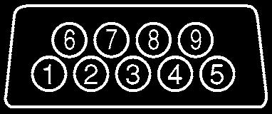
23 Input Block Section 2-2 Mounting Method Panel 2-2 Input Block 1, 2, Insert the K3NR into the mounting hole on the panel. 2. Hook the fixture claws onto the side holes. 3. Mount a fixing metal to the right and left sides as shown above and while keeping them in balance, alternately tighten each screw until the ratchet becomes idle Terminal Arrangement Sensor power supply (80 ma max. at 12 VDC) 100 to 240 to VAC 12 to 24 VDC Open collector input Voltage pulse input Note Voltage pulse input is available for the K3NR-NB -. 13
24 Input Block Section Wiring Precautions Wiring Do not make any mistake in polarity when supply DC power to the K3NR. Do not wire power lines alongside the signal lines of the K3NR in order to prevent the K3NR from noise interference. Wire the terminal block with crimp terminals. Tighten each screw to a torque of 0.78 N m (8 kgf cm). Power Supply Apply 100 to 240 VAC or 12 to 24 VDC to terminals 8 and 9. Open Collector Input Connect the pulse output from sensor A to terminal 1. Connect the pulse output from sensor B to terminal 2. Terminals 10 and 11 are exclusively used for a power supply with an output of 80 ma at 12 VDC to sensor A or B. If power is supplied to the sensor A or B from a different power source, do not use terminal 10. Do not connect a sensor with open collector output to terminal 10. Refer to the following for sensor connections. Sensor (with NPN output) +12 V Sensor (with PNP output) +12 V Residual voltage with sensor turned on: 3 V max. Current leakage with sensor turned off: 1.5 ma max. Switching load current: 20 ma or greater. Must be able to dependably switch a load current of 5 ma max. Photoelectric sensors, proximity sensors, rotary encoders, and relays can be connected as sensors to the K3NR. Voltage Pulse Input Connect the pulse output of sensor A to terminal 3. Connect the pulse output of sensor B to terminal 4. Terminals 10 and 11 are exclusively used for a power supply with an output of 80 ma at 12 VDC to sensor A or B. If power is supplied to the sensor A or B from a different power source, do not use terminal 10. Do not connect a sensor with voltage pulse output to terminal 10. Refer to the following for sensor connections. Sensor +12 V H level (sensor output ON): 4.5 to 30 VDC L level (sensor output OFF): 30 to 2 VDC Auxiliary Power Supply Terminals 10 and 11 are exclusively used for power supply to sensors with an output of 80 ma at 12 VDC ± 10%. 14
25 Input Block Section 2-2 External Signal Input HOLD Input RESET Input BANK Input Connect external signal inputs to terminals 5 through 7 and 13 through 15. Terminals 7 and 13 are connected to each other internally. Short-circuited together internally. Connect HOLD input to terminal 5. Connect RESET input to terminal 6. Connect BANK inputs to terminals 14 and 15 for BANK1 and BANK2. If open collector input is used as external signal input, the transistor must satisfy the following conditions. Residual voltage with transistor turned on: 3 V max. Current leakage with transistor turned off: 1.5 ma max. Switching load current: 20 ma or greater. Approximately 5 V is imposed between COM and terminals 5 to 7 with a current flow of approximately 18 ma (a nominal value) at the time of external input shortcircuiting. 15
26 Output Board Section Output Board Terminal Arrangement K3NR with Relay Output Board, K31-C1, -C2. -C5 K3NR with Transistor Output Board, K31-T1, -T2 K3NR with Linear Output Board, K31-L1, -L2, -L3, -L4, -L5, -L6, -L7, -L8, -L9, -L10 K3NR with RS-485 Output Board, K31-FLK2, -FLK5 K3NR with BCD Output Board, K31-B2, -B4 K3NR with RS232C + Transistor Output Board, K31-FLK4 16


27 Output Board Section 2-3 K3NR with RS Transistor Output Board, K31-FLK6 K3NR with RS-232C Output Board, K31-FLK1 K3NR with RS-422 Output Board, K31-FLK3 17
28 Output Board Section Relay Output Board The following figures show the connections for relay output. K3NR with 3 Relay Output Boards, K31-C1 K3NR with 5 Relay Output Boards, K31-C2 H comparative output HH comparative output H comparative output PASS output PASS output L comparative output K3NR with 5 Relay Output Boards, K31-C5 L comparative output LL comparative output HH comparative output H comparative output PASS output L comparative output LL comparative output The following contact output conditions are required. 5 A (resistive load) at 250 VAC 1.5 A (inductive load) at 250 VAC 5 A (resistive load) at 30 VDC 1.5 A (inductive load) at 30 VDC 18
29 Output Board Section Transistor and Combination Output Board K3NR with Transistor Output Board, K31-T1 or K31-T2 K3NR with Linear Output Board, K31-L4, -L5, -L6, -L9, -L10 K3NR with RS Relay Output Boards, K31-FLK5 K3NR with BCD Output Board, K31-B2 or K31-B4 K3NR with RS232C + 5 Transistor Output Boards, K31-FLK4 K3NR with RS Transistor Output Boards, K31-FLK6 21 HH comparative output 32 HH comparative output 1 HH comparative output 22 H comparative output 33 H comparative output 2 H comparative output 23 PASS output 34 PASS output 4 PASS output 24 L comparative output 35 L comparative output 5 L comparative output 25 LL comparative output 36 LL comparative output 6 LL comparative output 26 COM 37 COM 3 COM Linear Output Board The following transistor output conditions are required. Maximum rated voltage: 24 VDC Load current: 50 ma Current leakage with transistor turned off: 100 µa The following figures show connections for linear output. K3NR with Linear Output Board, K31-L1 or K31-L4 + K3NR with Linear Output Board, K31-L2 or K31-L5 + K3NR with Linear Output Board, K31-L3 or K31-L6 + 4 to 20 ma 1 to 5 V 1 mv/10 digit The following linear output conditions are required. Linear output Permissible load Resolution Output error resistance 4 to 20 ma 600 Ω max ±0.5% FS 1 to 5 V 500 Ω min ±0.5% FS 1 mv/10 digit 1 kω min ±1.5% FS BCD Output Board Refer to Section 7 BCD Output for the terminal arrangement and interface. 19
30 SECTION 3 Operating Modes This section provides information on the basic functions of each operating mode. 3-1 Rotational/Circumferential Speed: Absolute Ratio: Error Ratio: Rotational Difference: Flow Rate Ratio: Passing Time: Pulse Counting:
31 Rotational/Circumferential Speed: Section Rotational/Circumferential Speed: FUNCTION Application example Measures the rotations of the roll. Basic Operation Multiplies the input frequency (Hz) of INA by 60 and displays the result in rpm. When the appropriate prescale value is selected, the rotational speed of the object is displayed. Obtain display value D as follows: D = f A x 60 x α f A : Input frequency of INA (Hz) α: Prescale value INB input will be ignored. SETTING Item Unit of display Prescale value Rotations rpm 1/N rps 1/60N Frequency of input Hz 1/60 pulse khz 1/60000 Rotational speed mm/s 1000πd/60N cm/s 100πd/60N m/s πd/60n m/min πd/n km/h 0.06πd/N Where, N: Number of pulses per rotation πd: Length (m) of one rotation Example: Displaying rotations (rpm) on condition that there are two pulses per revolution. Prescaling value (α) = 1/2 = 0.5 = x 10 1 Prescale value = X x 10 Y (X: mantissa, Y: exponent) X (mantissa) of input A = Y (exponent) of input A = 1 Refer to 4-2 Setting Mode. REFERENCE 22
32 Rotational/Circumferential Speed: Section 3-1 Hold Measured Value When the HOLD input is turned ON, measurement stops and the input measured just before the HOLD input turned ON is held. While the HOLD input is ON, the K3NR holds display output, comparative output, and BCD output. When the comparative output from the Output Board is connected to the HOLD input terminal, the value measured immediately after the occurrence of an error can be obtained. Performance Characteristics Accuracy of measurement Measurement range ON/OFF pulse width ±0.006% rdg ± 1 digit (ambient temperature: 23 C ± 5 C) Sensor with transistor output: 0.5 mhz to 50 khz Sensor with relay output: 0.5 mhz to 30 Hz Sensor with transistor output: 9 µs min. Sensor with relay output: 15 ms min. Response time Relay output Transistor output Output configuration BCD and transistor output Linear and transistor output Comparative output 200 ms max. BCD output Refer to page Linear output ms max. --- Communication and transistor output 23
33 Rotational/Circumferential Speed: Section 3-1 Available Functions Available functions in this mode are indicated as Yes in the following table. Menu Function Displayed Character Availability Reference page --- Max./Min. value display and reset --- Yes 103 Estimated frequency calculation --- Yes 129 Set value bank no. of set values Yes 50 (See note 2) HH set value H set value L set value LL set value Select bank no. of prescale value Yes 54 Prescaling value of input A X (mantissa) Y (exponent) Prescaling value of input B X (mantissa) Y (exponent) Decimal point position Yes Operating mode Yes 58 Input A sensor type Yes 60 Input B sensor type No Auto zero time of input A Yes 62 X (mantissa) Y (exponent) Auto zero time of input B X (mantissa) Y (exponent) Display time unit No 65 Communications unit no. (See note 1) Yes 67 Baud rate (See note 1) Yes Word length (See note 1) Yes 69 Stop bits (See note 1) Yes Parity bits (See note 1) Yes Process time for averaging measured value Yes 72 Startup compensation time Yes 74 Power failure memory No 76 Hysteresis (See note 1) Yes 78 Comparative output pattern (See note 1) Yes 80 H linear output range (See note 1) Yes 83 L Linear output range (See note 1) Yes Remote/Local programming (See note 1) Yes 86 Yes No No Note 1. The availability of the parameters depends on the type of selected Output Board. 2. The selected bank number will be displayed where an asterisk (*) appears. 24
34 Absolute Ratio: Section Absolute Ratio: FUNCTION Operation example Measures the rotation ratio of the rolls. Basic Operation Displays the absolute ratio of the frequencies of INA and INB in percentage. Obtain display value D as follows: D (%) = f B x β f A x α x 100 f A : Input frequency of INA (Hz) f B : Input frequency of INB (Hz) α: Prescale value of INA β: Prescale value of INB SETTING Mode Unit of display Prescale value Absolute ratio % Na and Nb or πda/na and πdb/nb Where, Na: Number of pulses per revolution from A input Nb: Number of pulses per revolution from B input πda: Circumference (m) per revolution for A input πdb: Circumference (m) per revolution for B input Example: Displaying absolute revolution rate using two rotary encoders each with 1,000 output pulses per revolution. Prescale value of INA (α) = 1/1000 = = x 10 3 Prescale value of INB (β) = 1/1000 = = x 10 3 Prescale value = X x 10 Y (X: mantissa, Y: exponent) X (mantissa) of input A = Y (exponent) of input A = 3 X (mantissa) of input B = Y (exponent) of input B = 3 Refer to 4-2 Setting Mode. REFERENCE 25
35 Absolute Ratio: Section 3-2 Hold Measured Value When the HOLD input is turned ON, measurement stops and the input measured just before the HOLD input turned ON is held. While the HOLD input is ON, the K3NR holds display output, comparative output, and BCD output. When the comparative output from the Output Board is connected to the HOLD input terminal, the value measured immediately after the occurrence of an error can be obtained. Performance Characteristics Accuracy of measurement Measurement range ON/OFF pulse width ±0.02% rdg ± 1 digit (ambient temperature: 23 C ± 5 C) Sensor with transistor output: 0.5 mhz to 50 khz Sensor with relay output: 0.5 mhz to 30 Hz Sensor with transistor output: 9 µs min. Sensor with relay output: 15 ms min. Response time Relay output Transistor output Output configuration BCD and transistor output Linear and transistor output Comparative output 200 ms max. BCD output Refer to page Linear output ms max. --- Communication and transistor output 26
36 Absolute Ratio: Section 3-2 Available Functions Available functions in this mode are indicated as Yes in the following table. Menu Function Displayed Character Availability Reference page --- Max./Min. value display and reset --- Yes 103 Estimated frequency calculation --- Yes 129 Set value bank no. of set values Yes 50 (See note 2) HH set value H set value L set value LL set value Select bank no. of prescale value Yes 54 Prescaling value of input A X (mantissa) Y (exponent) Prescaling value of input B X (mantissa) Y (exponent) Decimal point position Yes Operating mode Yes 58 Input A sensor type Yes 60 Input B sensor type Yes Auto zero timer of input A Yes 62 X (mantissa) Y (exponent) Auto zero timer of input B X (mantissa) Y (exponent) Display time unit No 65 Communications unit no. (See note 1) Yes 67 Baud rate (See note 1) Yes Word length (See note 1) Yes 69 Stop bits (See note 1) Yes Parity bits (See note 1) Yes Process time for averaging measured value Yes 72 Startup compensation time Yes 74 Power failure memory No 76 Hysteresis (See note 1) Yes 78 Comparative output pattern (See note 1) Yes 80 H linear output range (See note 1) Yes 83 L Linear output range (See note 1) Yes Remote/Local programming (See note 1) Yes 86 Note 1. The availability of the parameters depends on the type of selected Output Board. 2. The selected bank number will be displayed where an asterisk (*) appears. Yes Yes Yes 27
37 Error Ratio: Section Error Ratio: FUNCTION Application example Measures the speed of the conveyor belts and the error ratio in the rotation of the conveyor belts. Basic Operation Displays the error ratio of the frequency of INA and INB in percentage. Obtain display value D as follows: f A : Input frequency of INA (Hz) f B : Input frequency of INB (Hz) α: Prescale value of INA β: Prescale value of INB f B x β f A x α D (%) = x 100 f A x α SETTING Mode Unit of display Prescale value Error ratio % Na and Nb or πda/na and πdb/nb Where, Na: Number of pulses per revolution from A input Nb: Number of pulses per revolution from B input πda: Circumference (m) per revolution for A input πdb: Circumference (m) per revolution for B input Example: Displaying error ratio of two conveyor speeds (m/min) using two rotary encoders each with 100 output pulses per revolution and a circumference of m. Prescale value of INA (α) = 0.125/100 = = x 10 3 Prescale value of INB (β) = 0.125/100 = = x 10 3 Prescale value = X x 10 Y (X: mantissa, Y: exponent) X (mantissa) of input A = Y (exponent) of input A = 3 X (mantissa) of input B = Y (exponent) of input B = 3 Refer to 4-2 Setting Mode. REFERENCE 28
38 Error Ratio: Section 3-3 Hold Measured Value When the HOLD input is turned ON, measurement stops and the input measured just before the HOLD input turned ON is held. While the HOLD input is ON, the K3NR holds display output, comparative output, and BCD output. When the comparative output from the Output Board is connected to the HOLD input terminal, the value measured immediately after the occurrence of an error can be obtained. Performance Characteristics Accuracy of measurement Measurement range ON/OFF pulse width ±0.02% rdg ± 1 digit (ambient temperature: 23 C ± 5 C) Sensor with transistor output: 0.5 mhz to 50 khz Sensor with relay output: 0.5 mhz to 30 Hz Sensor with transistor output: 9 µs min. Sensor with relay output: 15 ms min. Response time Relay output Transistor output Output configuration BCD and transistor output Linear and transistor output Comparative output 200 ms max. BCD output Refer to page Linear output ms max. --- Communication and transistor output 29
39 Error Ratio: Section 3-3 Available Functions Available functions in this mode are indicated as Yes in the following table. Menu Function Displayed Character Availability Reference page --- Max./Min. value display and reset --- Yes 103 Estimated frequency calculation --- Yes 129 Set value bank no. of set values Yes 50 (See note 2) HH set value H set value L set value LL set value Select bank no. of prescale value Yes 54 Prescaling value of input A X (mantissa) Y (exponent) Prescaling value of input B X (mantissa) Y (exponent) Decimal point position Yes Operating mode Yes 58 Input A sensor type Yes 60 Input B sensor type Yes Auto zero time of input A Yes 62 X (mantissa) Y (exponent) Auto zero time of input B X (mantissa) Y (exponent) Display time unit No 65 Communications unit no. (See note 1) Yes 67 Baud rate (See note 1) Yes Word length (See note 1) Yes 69 Stop bits (See note 1) Yes Parity bits (See note 1) Yes Process time for averaging measured value Yes 72 Startup compensation time Yes 74 Power failure memory No 76 Hysteresis (See note 1) Yes 78 Comparative output pattern (See note 1) Yes 80 H linear output range (See note 1) Yes 83 L Linear output range (See note 1) Yes Remote/Local programming (See note 1) Yes 86 Yes Yes Yes Note 1. The availability of the parameters depends on the type of selected Output Board. 2. The selected bank number will be displayed where an asterisk (*) appears. 30
40 Rotational Difference: Section Rotational Difference: FUNCTION Application example Measures the rotational difference of the conveyor belts. Basic Operation Displays the rotational difference of INA and INB. Obtain display value D as follows: D (rpm) = f B x 60 x β f A x 60 x α f A : Input frequency of INA (Hz) f B : Input frequency of INB (Hz) α: Prescale value of INA β: Prescale value of INB SETTING Mode Unit of display Prescale value Rotational rpm INA 1/60Na Difference INB 1/60Nb Hz (Input pulse INA 1/60 frequency) INB 1/60 mm/sec INA 1000πda/60Na INB 1000πdb/60Nb m/sec INA πda/60na INB πdb/60nb m/min INA πda/na INB πdb/nb Where, Na: Number of pulses per revolution from A input Nb: Number of pulses per revolution from B input πda: Circumference (m) per revolution for A input πdb: Circumference (m) per revolution for B input Example: Displaying error in frequency (Hz) using two rotary encoders each with 100 output pulses per revolution. Prescale value of INA (α) = 1/60 = x 10 2 Prescale value of INB (β) = 1/60 = x 10 2 Prescale value = X x 10 Y (X: mantissa, Y: exponent) X (mantissa) of input A = Y (exponent) of input A = 2 X (mantissa) of input B = Y (exponent) of input B = 2 31
41 Rotational Difference: Section 3-4 Refer to 4-2 Setting Mode. REFERENCE Hold Measured Value When the HOLD input is turned ON, measurement stops and the input measured just before the HOLD input turned ON is held. While the HOLD input is ON, the K3NR holds display output, comparative output, and BCD output. When the comparative output from the Output Board is connected to the HOLD input terminal, the value measured immediately after the occurrence of an error can be obtained. Performance Characteristics Accuracy of measurement Measurement range ON/OFF pulse width ±0.02% rdg ± 1 digit (ambient temperature: 23 C ± 5 C) Sensor with transistor output: 0.5 mhz to 50 khz Sensor with relay output: 0.5 mhz to 30 Hz Sensor with transistor output: 9 µs min. Sensor with relay output: 15 ms min. Response time Relay output Transistor output Output configuration BCD and transistor output Linear and transistor output Comparative output 200 ms max. BCD output Refer to page Linear output ms max. --- Communication and transistor output 32
42 Rotational Difference: Section 3-4 Available Functions Available functions in this mode are indicated as Yes in the following table. Menu Function Displayed Character Availability Reference page --- Max./Min. value display and reset --- Yes 103 Estimated frequency calculation --- Yes 129 Set value bank no. of set values Yes 50 (See note 2) HH set value H set value L set value LL set value Select bank no. of prescale value Yes 54 Prescaling value of input A X (mantissa) Y (exponent) Prescaling value of input B X (mantissa) Y (exponent) Decimal point position Yes Operating mode Yes 58 Input A sensor type Yes 60 Input B sensor type Yes Auto zero time of input A Yes 62 X (mantissa) Y (exponent) Auto zero time of input B X (mantissa) Y (exponent) Display time unit No 65 Communications unit no. (See note 1) Yes 67 Baud rate (See note 1) Yes Word length (See note 1) Yes 69 Stop bits (See note 1) Yes Parity bits (See note 1) Yes Process time for averaging measured value Yes 72 Startup compensation time Yes 74 Power failure memory No 76 Hysteresis (See note 1) Yes 78 Comparative output pattern (See note 1) Yes 80 H linear output range (See note 1) Yes 83 L Linear output range (See note 1) Yes Remote/Local programming (See note 1) Yes 86 Yes Yes Yes Note 1. The availability of the parameters depends on the type of selected Output Board. 2. The selected bank number will be displayed where an asterisk (*) appears. 33
43 Flow Rate Ratio: Section Flow Rate Ratio: FUNCTION Application example A B Measures the flow rate ratio of the mixture of A and B. Basic Operation From the frequency of INA and INB, displays the flow rate ratio of INB in percentage. Obtain display value D as follows: D (%) = f B x β f A x α + f B x β x 100 f A : Input frequency of INA (Hz) f B : Input frequency of INB (Hz) α: Prescale value of INA β: Prescale value of INB SETTING Mode Unit of display Prescale value Flow rate ratio % INA Na INB Nb Where, Na: Number of pulses for specific quantity of A input Nb: Number of pulses for specific quantity of B input Example: Displaying mixed liquid concentration calculated from the flow rate ratio of two flow sensors each with a capacity of 10 /400 rpm. Prescale value of INA (α) = 10/400 = = x 10 2 Prescale value of INB (β) = 10/400 = = x 10 2 Prescale value = X x 10 Y (X: mantissa, Y: exponent) X (mantissa) of input A = Y (exponent) of input A = 2 X (mantissa) of input B = Y (exponent) of input B = 2 Refer to 4-2 Setting Mode. REFERENCE 34
44 Flow Rate Ratio: Section 3-5 Hold Measured Value When the HOLD input is turned ON, measurement stops and the input measured just before the HOLD input turned ON is held. While the HOLD input is ON, the K3NR holds display output, comparative output, and BCD output. When the comparative output from the Output Board is connected to the HOLD input terminal, the value measured immediately after the occurrence of an error can be obtained. Performance Characteristics Accuracy of measurement Measurement range ON/OFF pulse width ±0.02% rdg ± 1 digit (ambient temperature: 23 C ± 5 C) Sensor with transistor output: 0.5 mhz to 50 khz Sensor with relay output: 0.5 mhz to 30 Hz Sensor with transistor output: 9 µs min. Sensor with relay output: 15 ms min. Response time Relay output Transistor output Output configuration BCD and transistor output Linear and transistor output Comparative output 200 ms max. BCD output Refer to page Linear output ms max. --- Communication and transistor output 35
45 Flow Rate Ratio: Section 3-5 Available Functions Available functions in this mode are indicated as Yes in the following table. Menu Function Displayed Character Availability Reference page --- Max./Min. value display and reset --- Yes 103 Estimated frequency calculation --- Yes 129 Set value bank no. of set values Yes 50 (See note 2) HH set value H set value L set value LL set value Select bank no. of prescale value Yes 54 Prescaling value of input A X (mantissa) Y (exponent) Prescaling value of input B X (mantissa) Y (exponent) Decimal point position Yes Operating mode Yes 58 Input A sensor type Yes 60 Input B sensor type No Auto zero time of input A Yes 62 X (mantissa) Y (exponent) Auto zero time of input B X (mantissa) Y (exponent) Display time unit No 65 Communications unit no. (See note 1) Yes 67 Baud rate (See note 1) Yes Word length (See note 1) Yes 69 Stop bits (See note 1) Yes Parity bits (See note 1) Yes Process time for averaging measured value Yes 72 Startup compensation time Yes 74 Power failure memory No 76 Hysteresis (See note 1) Yes 78 Comparative output pattern (See note 1) Yes 80 H linear output range (See note 1) Yes 83 L Linear output range (See note 1) Yes Remote/Local programming (See note 1) Yes 86 Yes Yes Yes Note 1. The availability of the parameters depends on the type of selected Output Board. 2. The selected bank number will be displayed where an asterisk (*) appears. 36
46 Passing Time: Section Passing Time: FUNCTION Application example Measures the passing time for a conveyor line. Distance Basic Operation Measures and displays the input pulse frequency of INA in units of seconds. By selecting an appropriate prescale value, object passing time D in the range determined by the prescale value will be displayed. Obtain display value D as follows: D (sec) = 1/f A x α f A : INA input frequency (Hz) α: prescale value of INA Rotational speed = Input frequency (f) x (1/No. of pulses (N) per 1 cycle) Circumferential speed = Circumference of roll (πd) x rotational speed Passing time = Processing length (L)/Circumferential speed INB input will be ignored. Passing time is measured in this mode. Therefore, if the K3NR does not receive any pulses for a certain period, the K3NR estimates passing time using the estimated frequency calculation function and increases the displayed value. Mode Unit of display value Prescale value Passing time sec L/(πd/N) SETTING N = No. of pulses per 1 cycle from input A πd = Circumferential length (m) per 1 cycle L = Processing length (m) Note The K3NR can display the hour, minute, and second. Refer to page 65 for details. Example: Displaying passing time (sec) using a rotary encoder with 100 output pulses per revolution. Circumference of rotary encoder = m Process length = 5 m Prescaling value (α) = 5/(0.125/100) = 4000 = x 10 3 Prescale value = X x 10 Y (X: mantissa, Y: exponent) X (mantissa) of input A = Y (exponent) of input A = 3 Refer to 4-2 Setting Mode. REFERENCE 37
47 Passing Time: Section 3-6 Hold Measured Value When the HOLD input is turned ON, measurement stops and the input measured just before the HOLD input turned ON is held. While the HOLD input is ON, the K3NR holds display output, comparative output, and BCD output. When the comparative output from the Output Board is connected to the HOLD input terminal, the value measured immediately after the occurrence of an error can be obtained. Performance Characteristics Accuracy of measurement Measurement range ON/OFF pulse width ±0.006% rdg ± 1 digit (ambient temperature: 23 C ± 5 C) Sensor with transistor output: 0.5 mhz to 50 KHz Sensor with relay output: 0.5 mhz to 30 Hz Sensor with transistor output: 9 µs min. Sensor with relay output: 15 ms min. Response time Relay output Transistor output Output configuration BCD and transistor output Linear and transistor output Comparative output 200 ms max. BCD output Refer to page Linear output ms max. --- Communication and transistor output 38
48 Passing Time: Section 3-6 Available Functions Available functions in this mode are indicated as Yes in the following table. Menu Function Displayed Character Availability Reference page --- Max./Min. value display and reset --- Yes 103 Estimated frequency calculation --- Yes 129 Set value bank no. of set values Yes 50 (See note 2) HH set value H set value L set value LL set value Select bank no. of prescale value Yes 54 Prescaling value of input A X (mantissa) Y (exponent) Prescaling value of input B X (mantissa) Y (exponent) Decimal point position Yes Operating mode Yes 58 Input A sensor type Yes 60 Input B sensor type No Auto zero time of input A Yes 62 X (mantissa) Y (exponent) Auto zero time of input B X (mantissa) Y (exponent) Display time unit No 65 Communications unit no. (See note 1) Yes 67 Baud rate (See note 1) Yes Word length (See note 1) Yes 69 Stop bits (See note 1) Yes Parity bits (See note 1) Yes Process time for averaging measured value Yes 72 Startup compensation time Yes 74 Power failure memory No 76 Hysteresis (See note 1) Yes 78 Comparative output pattern (See note 1) Yes 80 H linear output range (See note 1) Yes 83 L Linear output range (See note 1) Yes Remote/Local programming (See note 1) Yes 86 Yes No No Note 1. The availability of the parameters depends on the type of selected Output Board. 2. The selected bank number will be displayed where an asterisk (*) appears. 39
49 Pulse Counting: Section Pulse Counting: FUNCTION Application example Counts the number of objects. Basic Operation Counts the number of pulses of INA and displays the result. Obtain display value D as follows: D (pulse count) = C x α C: Pulse count of INA α: Prescale value Hold Displayed Value By turning the HOLD input ON, the displayed value can be put on HOLD. While the HOLD input is ON, the pulse counting operation continues, as does comparative output and BCD output. In this case, using the HOLD input is similar to checking a lap time with a stopwatch. Interruption of Pulse Counting With INB input ON, the pulse counting operation is interrupted and the measured value, comparative outputs, and BCD output are on HOLD. Pulse counting will not begin while INB input is ON. Clearing Accumulated Value When the RESET input turns ON, the accumulated value is cleared to zero. Pulse counting will not start while the RESET input is ON. The accumulated value will be stored or cleared to zero when the K3NR is turned off, and depends on the setting of the power failure memory ( ) at option menu. Note By connecting comparative output with the RESET input terminal, the K3NR can be used as a single-mode preset counter. 40
50 Pulse Counting: Section 3-7 Comparative Output With operating mode 7, comparative output L, LL, H, or HH turns ON when the measured value exceeds the set value. Refer to following chart for details. INA input RESET input Process value HH set value H set value LL set value L set value HH comparative output H comparative output PASS output L comparative output LL comparative output SETTING Mode Unit of display value Prescale value 1 pulse = n counts Count n n pulses = 1 count Count 1/n Example: Counting four pulses as a single unit to be displayed. Prescaling value (α) = 1/4 = 0.25 = 0.25 x 10 0 Prescale value = X x 10 Y (X: mantissa, Y: exponent) X (mantissa) of input A = 0.25 Y (exponent) of input A = Setting Mode. REFERENCE Performance Characteristics Maximum counting speed Counting range Response time of HOLD or RESET input ON/OFF pulse width Sensor with transistor output: 50 kcps Sensor with relay output: 30 cps 0 to 4 G (with 32-bit counter) 20 ms max. Sensor with transistor output: 9 µs min. Sensor with relay output: 15 ms min. 41
51 Pulse Counting: Section 3-7 Response time Relay output Transistor output Output configuration BCD and transistor output Linear and transistor output Communication and transistor output Comparative output 10 ms max. 1 ms max. 20 ms max. 20 ms max. 1 ms max. BCD output Refer to page Linear output ms max. --- Maximum Pulse Counting Speed Maximum pulse counting speed is the maximum speed at which the K3NR can count INA input pulses accurately. If comparative output is used as control output, the maximum pulse counting speed can be obtained as follows: Maximum counting speed (cps) = 1/Delay in comparative outputs (sec) If comparative output is directly connected to RESET input, the maximum pulse counting speed can be obtained as follows: Maximum counting speed (cps) = 1/Delay in comparative outputs (sec) + Response time of RESET input (sec) Response Time of HOLD or RESET Input The response time of the HOLD or RESET input is the time required for the K3TR to accept HOLD or RESET input after the HOLD or RESET input turns ON. This is illustrated in the following diagram. INA Comparative output HOLD or RESET input Delay in comparative outputs Acceptance of HOLD or RESET input Response time of HOLD or RESET input (20 ms max.) 42
52 Pulse Counting: Section 3-7 Available Functions Available functions in this mode are indicated as Yes in the following table. Menu Function Displayed Character Availability Reference page --- Max./Min. value display and reset --- Yes 103 Estimated frequency calculation --- No 129 Set value bank no. of set values Yes 50 (See note 2) HH set value H set value L set value LL set value Select bank no. of prescale value Yes 54 Prescaling value of input A X (mantissa) Y (exponent) Prescaling value of input B X (mantissa) Y (exponent) Decimal point position Yes Operating mode Yes 58 Input A sensor type Yes 60 Input B sensor type Yes Auto zero time of input A No 62 X (mantissa) Y (exponent) Auto zero time of input B X (mantissa) Y (exponent) Display time unit No 65 Communications unit no. (See note 1) Yes 67 Baud rate (See note 1) Yes Word length (See note 1) Yes 69 Stop bits (See note 1) Yes Parity bits (See note 1) Yes Process time for averaging measured value No 72 Startup compensation time No 74 Power failure memory Yes 76 Hysteresis (See note 1) No 78 Comparative output pattern (See note 1) No 80 H linear output range (See note 1) Yes 83 L Linear output range (See note 1) Yes Remote/Local programming (See note 1) Yes 86 Yes No No Note 1. The availability of the parameters depends on the type of selected Output Board. 2. The selected bank number will be displayed where an asterisk (*) appears. 43
53 SECTION 4 Parameter Setting This section provides instructions for setting the parameters of the K3NR. Be sure to read this section before using the K3NR Frequency/Rate Meter for the first time. 4-1 Overview Heading Symbols Setting Procedures Setting Mode Selecting Setting Mode Menu Overview Setting Value Menu ( ) Bank No. of Set Value HH Set Value H Set Value L Set Value LL Set Value Prescaling Menu ( ) Bank No. of Prescale Prescaling Value X (Mantissa) of Input A Prescaling Value Y (Exponent) of Input A Prescaling Value X (Mantissa) of Input B Prescaling Value Y (Exponent) of Input B Decimal Point Position Setup Menu (setup) Operating Mode Sensor Type Auto Zero Time of Input A X (Mantissa) Auto Zero Time of Input A Y (Exponent) Auto Zero Time of Input B X (Mantissa) Auto Zero Time of Input B Y (Exponent) Time Unit Communications Unit Number Baud Rate Word Length Stop Bits Parity Bits Option Menu ( ) Process Time for Averaging Measured Value Startup Compensation Time Power Failure Memory Hysteresis Comparative Output Pattern Upper Limit (H) of Linear Output Range Lower Limit (L) of Linear Output Range Remote/Local Programming Protect Mode Selecting Protect Mode Menu Overview Protect Menu ( ) All Key Protect Setting Value Change Prohibit Counting Value Reset Prohibit Maximum/Minimum Value Clear Prohibit Security
54 Overview Section Overview Heading Symbols The following symbols are used for headings in this section. This symbol precedes an explanation of the parameter s meaning and function. FUNCTION SETTING This symbol precedes a description of the settings, setting range, and default value. PROCEDURE This symbol precedes an explanation of procedures for parameters that specify operations. This symbol precedes a listing of references and related parameters. REFERENCE MODELS This symbol precedes a listing of the models in which this parameter can be used Setting Procedures 46 The K3NR has four modes: RUN mode for normal operations, Setting mode for initial parameter input, Protect mode for lock-out configuration, and Maintenance mode for initializing set values. The parameters that are accessible on any individual K3NR will vary depending on the Output Board installed. Refer to Appendix D Available Parameters. The K3NR is in RUN mode when the K3NR is turned on. Parameter settings in protect or setting mode are described below on the basis that the parameters are set for the first time. For the operation in RUN mode, refer to Section 5 Operations in RUN Mode. The setting examples are provided on condition that the factory-set values of the K3NR have not been changed.
55 Setting Mode Section Setting Mode Selecting Setting Mode The K3NR in RUN mode will go into setting mode if the Mode Key is pressed for 1 s minimum. The K3NR in setting mode will go into RUN mode if the Escape Key is pressed. Press the Mode and Shift Keys while turning the K3NR on. Power On Maintenance mode Press the Escape and Up Keys for 1 second. RUN mode RUN mode Protect mode 1 second Setting mode The menu in each mode changes whenever the Mode Key is pressed. If the Mode Key is pressed for more than one second while a menu is displayed, a parameter will be displayed. The parameter changes whenever the Mode Key is pressed. If the Shift Key is pressed while a parameter is displayed, the parameter will be ready to change. Press the Up Key to change parameters. The digit of a set value is selected with the Shift Key and changed with the Up Key. The PROG indicator is lit while a menu or parameter is displayed. The PROG indicator flashes during a set value change. Note If the operating mode is changed, all the other parameters will be set to default values except communication setting and set values in protect mode. Therefore, set the operating mode and sensor type first. 47
56 Setting Mode Section Menu Overview RUN Mode Power On Press the Mode and Shift Keys while turning the K3NR on. Maintenance Mode Refer to Section 6 Useful Functions. Refer to Section 5 Operations in RUN Mode. Press the Escape and Up Keys for 1 second. Protect Mode Setting Mode Press the Mode Key for 1 second. Refer to 4-3 Protect Mode. Setting value menu Prescaling menu Press the Mode Key for 1 second. (see note 1) Bank no. of set value 1 to 4 Press the Mode Key for 1 second. Bank no. of prescale value HH setting value Prescaling value of input A X (mantissa) H setting value Prescaling value of input A Y (exponent) L setting value Prescaling value of input B X (mantissa) LL setting value Prescaling value of input B Y (exponent) Output Test Decimal point position Refer to Section 6 Useful Functions. Note 1. When making new settings or changing settings of each parameter, press the Shift Key to shift to the setting state. The input will be updated automatically if no change is made for five seconds. 2. The K3NR stops measurement in setting mode. Some menus cannot be set according to the Output Board selected. If the operating mode is changed, all the other parameters will be set to default values except communication setting and set values in protect mode. Therefore, set the operating mode and sensor type. 48
57 Setting Mode Section 4-2 Setup menu Option menu Operating mode Press the Mode Key for 1 second. Press the Mode Key for 1 second. Process time for averaging measured value Input A sensor type Startup compensation time Input B sensor type Power failure memory Auto zero time of input A X (mantissa) Hysteresis Auto zero time of input A Y (exponent) Comparative output pattern Auto zero time of input B X (mantissa) H linear output range Auto zero time of input B Y (exponent) L linear output range Time unit Remote/Local processing Communications unit no. Baud rate Word length Stop bits Parity bits 49
58 Setting Mode Section Setting Value Menu ( ) Bank No. of Set Value HH Set Value H Set Value L Set Value LL Set Value FUNCTION SETTING There are two basic methods for setting HH, H, L, and LL set values: by entering during RUN mode via the front-panel buttons, setting in Setting mode, or by the teaching function. Setting Setting range Default Set value bank 1 to 4 1 HH set value 19,999 to ,999 H set value 99,999 L set value LL set value Set the decimal point position in the prescaling menu. Refer to 6-1 Teaching Function. REFERENCE The menu is only available for the K3NR with Comparative Output Board. MODELS 50


59 Setting Mode Section 4-2 SETTING EXAMPLE Follow the steps described below to input the following. Setting value bank = 2 HH setting value = 8000 H setting value = 6000 L setting value = 4000 LL setting value = , 2, Press the Mode Key for more than one second while the setting value menu is displayed. The setting value bank setting will be displayed. 2. Press the Shift Key to display the set value for changing. The PROG indicator will flash. 3. Press the Up Key to set the value to. The input will be validated automatically if no change is made for five seconds. The setting value bank setting will be displayed again. Note Press the Mode Key to enter the set value immediately. The HH setting value of bank 2 setting will be displayed for setting the next parameter. 4. Press the Mode Key to display the HH setting value of bank 2 setting. 5. Press the Shift Key to display the set value for changing. The PROG indicator will flash. 51


60 Setting Mode Section Press the Up and Shift Keys to set the value to. The input will be validated automatically if no change is made for five seconds. The HH setting value of bank 2 setting will be displayed again. Note Press the Mode Key to enter the set value immediately. The H setting value of bank 2 setting will be displayed for setting the next parameter. 7. Press the Mode Key to display the H setting value of bank 2 setting. 8. Press the Shift Key to display the set value for changing. The PROG indicator will flash. 9. Press the Up and Shift Keys to set the value to. The input will be validated automatically if no change is made for five seconds. The H setting value of bank 2 setting will be displayed again. Note Press the Mode Key to enter the set value immediately. The L setting value of bank 2 setting will be displayed for setting the next parameter. 10. Press the Mode Key to display the L setting value of bank 2 setting. 11. Press the Shift Key to display the set value for changing. The PROG indicator will flash. 52


61 Setting Mode Section Press the Up and Shift Keys to set the value to. The input will be validated automatically if no change is made for five seconds. The L setting value of bank 2 setting will be displayed again. Note Press the Mode Key to enter the input immediately. The LL setting value setting will be displayed for setting the next parameter. 13. Press the Mode Key to display the LL setting value of bank 2 setting. 14. Press the Mode Key to display the set value for changing. The PROG indicator will flash. 15. Press the Up and Shift Keys to set the value to. The input will be validated automatically if no change is made for five seconds. The LL setting value setting will be displayed again. Note Press the Mode Key to enter the set value immediately. The setting value bank setting will be displayed for setting the next parameter. 16. Press the Escape Key to display the setting value menu. 53
62 Setting Mode Section Prescaling Menu ( ) Bank No. of Prescale Prescaling Value X (Mantissa) of Input A Prescaling Value Y (Exponent) of Input A Prescaling Value X (Mantissa) of Input B Prescaling Value Y (Exponent) of Input B Decimal Point Position FUNCTION To display rotational speeds, circumferential speeds, or other values based on input pulse calculations, the rotational speed must be multiplied by a factor input before the input pulses are measured. This factor is called a prescale value. Display value = Measured data x Prescaling value Prescaling values can be set within a range between x 10 9 and x Example: Setting prescaling value with the input of two pulses per revolution. Unit: rpm Operating Mode: 1 Object to be measured Proximity Sensor SETTING Two pulses are output per revolution. Therefore, the prescaling value is calculated: 0.5 x 10 0 = 5.0 x 10 1 = = = Note Use prescaling banks 1 through four if more than one prescaling value needs to be set. Input type Setting Default : Bank no. of prescale OFF/1 to 4 OFF : Prescaling value X (mantissa) to of input A : Prescaling value Y (exponent) 9 to 9 0 of input A : Prescaling value X (mantissa) to of input B : Prescaling value Y (exponent) of input B 9 to 9 0 : Decimal point position Operating modes 3 and 4: One of the 1st to 3rd digits from the right Other modes: One of the 1st to 4th digits from the right No decimal point position setting 54

 of input A = 1")


63 Setting Mode Section 4-2 Refer to 6-1 Teaching Function. REFERENCE SETTING EXAMPLE Follow the steps described below to input the following. Operating mode = F1 Prescaling bank = OFF Prescaling value X (mantissa) of input A = Prescaling value Y (exponent) of input A = 1 Decimal point =. (1st digit from the right) 1, 2, Press the Mode Key for more than one second while the prescaling menu is displayed. The prescaling bank setting will be displayed. 2. Press the Shift Key to display for changing. The PROG indicator will flash. 3. Press the Up Key to change the prescaling bank setting. The input will be validated automatically if no change is made for five seconds. The prescaling bank setting will be displayed again. Note Press the Mode Key to enter the set value immediately. The prescaling value X (mantissa) of input A setting will be displayed for setting the next parameter. 4. Press the Mode Key to display the prescaling value X (mantissa) of input A setting. 55

 of input A setting will be displayed for setting the next parameter. 7.")

 Press the Mode Key to enter the set value immediately. The decimal point position setting will be displayed again.")
64 Setting Mode Section Press the Shift Key to display the set value for changing. The PROG indicator will flash. 6. Press the Up and Shift Keys to set the value to. The input will be validated automatically if no change is made for five seconds. The prescaling value X (mantissa) of input A setting will be displayed again. Note Press the Mode Key to enter the set value immediately. The prescaling value X (mantissa) of input A setting will be displayed for setting the next parameter. 7. Press the Mode Key to display the prescaling value Y (exponent) of input A setting. 8. Press the Shift Key to display the set value for changing. 9. Press the Up and Shift Keys to set the value to. The input will be validated automatically if no change is made for five seconds. The prescaling value Y (exponent) of input A setting will be displayed again. Note a) Press the Mode Key to enter the set value immediately. The decimal point position setting will be displayed again. b) If the set operating mode is F2 through F5, the prescaling value X (mantissa) of input B setting will be displayed. 56
65 Setting Mode Section Press the Mode Key to display the decimal point position setting. Note If the set operating mode is F2 through F5, the prescaling value X (mantissa) of input B setting will be displayed. 11. Press the Shift Key to display for changing. 12. Press the Shift Key to set. The input will be validated automatically if no change is made for five seconds. The decimal point position setting will be displayed again. Note Press the Mode Key to enter the set value immediately. The prescaling bank setting will be displayed for setting the next parameter. 13. Press the Escape Key to display the prescaling menu. 57
66 Setting Mode Section Setup Menu ( ) Operating Mode FUNCTION SETTING Use this menu to select the operating mode of the K3NR. All parameters will be set to default values if any change is made in this parameter except to those for the communications and protect settings. : Displays the number of circumferential or rotational speed of input A. through : Displays the result of the arithmetic operation of two different revolutions. : Displays the value of passing time calculated from the frequency or processing length of input A. : Displays the pulse counting of input A. : : : : : : : Setting Rotational/circumferential speed Absolute ratio Error ratio Rotational difference Flow rate ratio Passing time Pulse counting Default Refer to Section 3 Operating Modes. REFERENCE SETTING EXAMPLE Follow the steps described below to select the rotational difference setting. 1, 2, Press the Mode Key for more than one second while the setup menu is displayed. The operating mode setting will appear. 2. Press the Shift Key to display for changing. The PROG indicator will flash. 58
67 Setting Mode Section Repeatedly press the Up Key until is displayed. The displayed setting will be validated automatically if no change is made for five seconds. The operating mode setting will be displayed again. Note Press the Mode Key to enter the displayed setting immediately. The next parameter will be displayed for setting. 4. Repeatedly press the Escape Key until the setup menu is displayed. 59
 or (passing time).")
68 Setting Mode Section 4-2 Sensor Type FUNCTION SETTING Specifies the type of sensors for input A and input B. The sensor type of input B cannot be selected if the operating mode of the K3NR is set to (rotational/circumferential speed) or (passing time). Open Collector Input Sensor type Normally open Normally closed Default Transistor input Relay input Normally Open Model: The sensor output is OFF (open) when the sensor is not sensing an object. Normally Closed Model: The sensor output is ON (closed) when the sensor is not sensing an object. Voltage Pulse Input Sensor type Active high (H) Active low (L) Default Voltage pulse input SETTING EXAMPLE Follow the steps described below to set input A to in operating mode (rotational/circumferential speed). 1, 2, Press the Mode Key for more than one second while the setup menu is displayed. The operating mode setting will appear. 2. Press the Mode Key to display input A sensor type setting. 3. Press the Shift Key to display for changing. The PROG indicator will flash. 60
69 Setting Mode Section Press the Up and Shift Keys to display. The displayed value will be validated automatically if no change is made for five seconds. The input A sensor type setting will be displayed again. Note Press the Mode Key to enter the displayed setting immediately. The next parameter will be displayed. 5. Press the Escape Key to display the setup menu. 61

70 Setting Mode Section 4-2 Auto Zero Time of Input A X (Mantissa) Auto Zero Time of Input A Y (Exponent) Auto Zero Time of Input B X (Mantissa) Auto Zero Time of Input B Y (Exponent) FUNCTION Calibrates the process value to zero forcibly if no input pulse is received for a certain period. This period is called auto-zero time. Refer to the following graph. Frequency Auto-zero time Time SETTING Logically, the input pulse frequency does not drop to zero perfectly due to the estimated frequency calculation of the K3NR. Therefore, the K3NR has a function to calibrate the frequency to zero forcibly if no input pulse is received for a certain period. Automatic zero time is determined by the following formula. Auto-zero time = X x 10 Y (s) (X: mantissa, Y: exponent) Note Auto-zero time must be longer than the value obtained by dividing one by the minimum frequency input of the K3NR. Auto-zero time must not be less than 0.1 s. If the operating mode of the K3NR is set to F7 (pulse counting), this parameter will not be available. : : : : Input type Setting Default Auto zero time of input A X (mantissa) Auto zero time of input A Y (exponent) Auto zero time of input B X (mantissa) Auto zero time of input B Y (exponent) to to to to REFERENCE Note For details, refer to page 129 for the estimated frequency calculation of the K3NR. SETTING EXAMPLE Follow the steps described below to set the value of auto-zero time to one second. 62


 setting. 6.")
71 Setting Mode Section 4-2 1, 2, Press the Mode Key for more than one second while the setup menu is displayed. The operating mode setting will appear. 2. Repeatedly press the Mode Key until the auto zero time of input A X (mantissa) setting is displayed. 3. Press the Shift Key to display the set value for changing. The PROG indicator will flash. 4. Press the Up and Shift Keys to set the value to. The input will be validated automatically if no change is made for five seconds. The auto zero time of input A X (mantissa) setting will be displayed again. Note Press the Mode Key to enter the set value immediately. The auto zero time of input A Y (exponent) setting will be displayed for setting the next parameter. 5. Press the Mode Key to display the auto zero time of input A Y (exponent) setting. 6. Press the Shift Key to display the set value for changing. 7. Press the Up and Shift Keys to set the value to. The input will be validated automatically if no change is made for five seconds. The auto zero time of input A Y (exponent) setting will be displayed again. 63
 setting will be displayed for setting the next parameter. 8.")
72 Setting Mode Section 4-2 Note Press the Mode Key to enter the set value immediately. The auto zero time of input B X (mantissa) setting will be displayed for setting the next parameter. 8. Press the Escape Key to display the setup menu. 64
73 Setting Mode Section 4-2 Time Unit The time unit can be selected to display the calculation results of F6 (passing time). FUNCTION SETTING Unit Display range Default to 99,999 Displayed in seconds within a range between 0 and 99,999 s. Displayed minutes within a range between 0 and 99,999 min. Displayed in hours, minutes, and seconds within a range between 0 h, 00 min, 00 s and 9 hrs, 59 min, 59 s. Displayed in minutes and seconds (1/100 s) within a range between 00 min, 00 s 0 and 59 min, 59 s, 9. SETTING EXAMPLE Follow the steps described below to set second unit setting. 1, 2, Press the Mode Key for more than one second while the setup menu is displayed. The operating mode setting will appear. 2. Repeatedly press the Mode Key until time unit setting is displayed. 3. Press the Shift Key to display for changing. The PROG indicator will flash. 65
74 Setting Mode Section Press the Up Key to display. The input will be validated automatically if no change is made for five seconds. The time unit setting will be displayed again. Note Press the Mode Key to enter the set value immediately. The next parameter will be displayed for setting. 5. Press the Escape Key to display the setup menu. 66
75 Setting Mode Section 4-2 Communications Unit Number Baud Rate FUNCTION Set a communications unit number as an identification number by which the host computer is connected to the K3NR. If more than one K3NR is connected in parallel, make sure that each communications unit number is unique. The baud rate should be set to the baud rate of the host computer. Communications Unit Number SETTING Setting range Unit Default 00 to Baud Rate Setting range : 1,200 bps / : 2,400 bps / : 4,800 bps / : 9,600 bps / :19.2 Kbps / : 38.4 Kbps Default 9600 This setting is available for the K3NR with the Communications Output Board. MODELS SETTING EXAMPLE Follow the steps described below to set the communications unit number to 15 and the baud rate to 19,200 bps. 1, 2, Press the Mode Key for more than one second while the setup menu is displayed. The operating mode setting will appear. 2. Repeatedly press the Mode Key until the communications unit number setting is displayed. 67


76 Setting Mode Section Press the Shift Key to display the prior set value for changing. The PROG indicator will flash. 4. Press the Up and Shift Keys to set the value to. The input value will be validated automatically if no change is made for five seconds. The communications unit number setting will be displayed again. Note Press the Mode Key to enter the set value immediately. The next parameter will be displayed for setting. 5. Press the Mode Key to display the baud rate setting. 6. Press the Shift Key to display the prior set value for changing. The PROG indicator will flash. 7. Press the Up Key to set the value to. The input will be validated automatically if no change is made for five seconds. The baud rate setting will be displayed again. Note Press the Mode Key to enter the set value immediately. The next parameter will be displayed again for setting. 8. Press the Up Key to enter the set value for setting the next parameter. The input value will be validated automatically if no change is made for five seconds. The baud rate setting will be displayed again. 68


77 Setting Mode Section 4-2 Word Length Stop Bits Parity Bits FUNCTION The communications format used for communicating with the host computer is set in the setup menu. Refer to the Communications Manual for the communications format in detail. Word Length SETTING Setting Unit Default 7/8 bit 7 Stop Bits Setting Unit Default 1/2 bit 2 Parity Bit : None : Even : Odd Setting Default This setting is available for the K3NR with the Communications Output Board. MODELS SETTING EXAMPLE Follow the steps described below to set the following. Word length: 8 bits Number of stop bits: 1 Parity bits: 1, 2, Press the Mode Key for more than one second while the setup menu is displayed. The operating mode setting will appear. 69
78 Setting Mode Section Repeatedly press the Mode Key until the word length setting is displayed. 3. Press the Shift Key to display the prior set value for changing. The PROG indicator will flash. 4. Press the Up Key to set the value to. The input value will be validated automatically if no change is made for five seconds. The word length setting will be displayed again. Note Press the Mode Key to enter the set value immediately. The next parameter will be displayed for setting. 5. Press the Mode Key to display the stop bit setting. 6. Press the Shift Key to display the set value for changing. 7. Press the Up Key to set the value to. The input will be validated automatically if no change is made for five seconds. The stop bit setting will be displayed again. Note Press the Mode Key to enter the set value immediately. The next parameter will be displayed for setting. 8. Press the Mode Key to display the parity bit setting. 70
79 Setting Mode Section Press the Shift Key to display for changing. 10. Press the Up Key to display. The setting will be validated automatically if no change is made for five seconds. The parity bit setting will be displayed again. Note Press the Mode Key to enter the setting immediately. The next parameter will be displayed for setting. When no operation is executed for five seconds 71
80 Setting Mode Section Option Menu ( ) Process Time for Averaging Measured Value FUNCTION The K3NR averages its measured value at regular preset intervals. Therefore, when the K3NR is used to measure the rpm of a machine, for example, the value indicated by the PV display will be stable without being influenced by the fluctuation of the input pulse intervals or the rotation of the machine. If the input pulse intervals are larger than the preset regular intervals, the K3NR calculates the rpm using the input pulse intervals. SETTING : : : : : : : Setting Averaged every 60 ms Averaged every 500 ms Averaged every 1 s Averaged every 2 s Averaged every 4 s Averaged every 8 s Averaged every 16 s Default REFERENCE Input value Display value Without average processing Input value Display value After average processing 72
81 Setting Mode Section 4-2 SETTING EXAMPLE Follow the steps described below to set the process time for averaging measured value to 4 s. 1, 2, Press the Mode Key for more than one second while the option menu is displayed. The process time for averaging measured value setting will appear. 2. Press the Shift Key to display present set value for changing. The PROG indicator will flash. 3. Repeatedly press the Up Key until is displayed. The setting will be validated automatically if no change is made for five seconds. The process time for averaging measured value setting will be displayed again. Note Press the Mode Key to enter the displayed setting immediately. The next parameter will be displayed. When no operation is executed for five seconds 73
82 Setting Mode Section 4-2 Startup Compensation Time FUNCTION The interval between the moment the K3NR is turned and the moment the K3NR starts measurement operation is set in the option menu. The startup compensation time parameter keeps the measurement operation from sending an unnecessary output corresponding to instantaneous, fluctuating input from the moment the K3NR is turned ON until the end of the preset period. Setting range Unit Default 0.0 to 99.9 S 0.0 SETTING The K3NR will display with all outputs turned OFF until the K3NR is in measurement operation. REFERENCE Display L set value Display = (measurement interrupted) Time Power ON Setting time L comparative output SETTING EXAMPLE Follow the steps described below to set the startup compensation time to 2 seconds. 1, 2, Press the Mode Key for more than one second while the option menu is displayed. The process time for averaging measured value setting will appear. 74


83 Setting Mode Section Press the Mode Key to display the startup compensation time setting. 3. Press the Shift Key to display the prior set value for changing. The PROG indicator will flash. 4. Press the Up and Shift Keys to set the value to. The setting will be validated automatically if no change is made for five seconds. The startup compensation time setting will be displayed again. Note Press the Mode Key to enter the set value immediately. The next parameter will be displayed for setting. When no operation is executed for five seconds 75
84 Setting Mode Section 4-2 Power Failure Memory Retains the process value at the time of power failure if the operating mode of the K3NR is set to F7 (pulse counting). FUNCTION SETTING Setting : Stored : Not Stored Default SETTING EXAMPLE Follow the steps described below to set to enable power failure memory. 1, 2, Press the Mode Key for more than one second while the option menu is displayed. The average processing setting will appear. 2. Repeatedly press the Mode Key until the power failure memory setting is displayed. 3. Press the Shift Key to display the set data for changing. The PROG indicator will flash. 4. Press the Up Key to display. The setting will be validated automatically if no change is made for five seconds. The power failure memory setting will be displayed again. Note Press the Mode Key to enter the displayed setting immediately. The next parameter will be displayed for setting. 76
85 Setting Mode Section 4-2 When no operation is executed for five seconds 5. Press the Escape Key to display the option menu. 77
86 Setting Mode Section 4-2 Hysteresis FUNCTION The hysteresis can be set in the option menu to prevent chattering of the output if the measured value fluctuates in the vicinity of the setting values. The hysteresis can be set within a range of 1 and 9999 digits for four consecutive digits beginning with the leftmost digit regardless of the decimal point. The value set to 0 is regarded as 1. The decimal point position set in the scaling menu becomes valid. Setting range Unit Default 1 to SETTING REFERENCE If the comparative output is a level output, however, the hysteresis will be enabled when the measured value starts to become smaller than the HH, H, LL, and L setting values. H setting value Measured value Hysteresis L setting value Hysteresis H comparative output L comparative output This setting is only available for the K3NR with the Comparative Output Unit. MODELS SETTING EXAMPLE Follow the steps described below to set the hysteresis to 30. 1, 2, Press the Mode Key for more than one second while the option menu is displayed. The average processing setting will appear. 78


87 Setting Mode Section Repeatedly press the Mode Key until the hysteresis setting is displayed. 3. Press the Shift Key to display the prior set value for changing. The PROG indicator will flash. 4. Press the Up and Shift Keys to set the value to. The setting will be validated automatically if no change is made for five seconds. The hysteresis setting will be displayed again. Note Press the Mode Key to enter the set value immediately. The next parameter will be displayed for setting. When no operation is executed for five seconds 79
88 Setting Mode Section 4-2 Comparative Output Pattern FUNCTION The pattern of HH, H, L, LL, and PASS comparative outputs is set in the option menu. This function is not available when the operating mode is set to F7. SETTING Setting : Standard output : Zone output : Level output Default REFERENCE Standard Output H or HH Comparative Output: Turns ON when the measured value is larger than the H or HH setting value. PASS Output: Turns ON when LL, L, H, and HH comparative outputs are all OFF. L or LL Comparative Output: Turns ON when the measured value is smaller than the L or LL setting value. HH setting value H setting value Measured value L setting value LL setting value HH comparative output H comparative output PASS L comparative output LL comparative output 80
89 Setting Mode Section 4-2 Level Output LL, L, H, or HH Comparative Output: Turns ON when the measured value exceeds the LL, L, H, or HH setting value. PASS Output: Turns ON when the LL, L, H, and HH comparative outputs are all OFF. HH setting value H setting value Measured value L setting value LL setting value HH comparative output H comparative output PASS L comparative output LL comparative output Zone Output HH Comparative Output: Turns ON when the measured value exceeds the HH setting value. H Comparative Output: Turns ON when the measured value is between the H and HH setting values. PASS Output: Turns ON when the measured value is between the L and H setting values. L Comparative Output: Turns ON when the measured value is between the LL and L setting values. LL Comparative Output: Turns ON when the measured value falls below the LL setting value. Be sure to set the setting values so they satisfy the following formula: LL < L < H < HH HH setting value H setting value Measured value L setting value LL setting value HH comparative output H comparative output PASS L comparative output LL comparative output 81
90 Setting Mode Section 4-2 This setting is only available for the K3NR with the Comparative Output Unit. MODELS SETTING EXAMPLE Follow the steps described below to set the comparative output pattern to level output. 1, 2, Press the Mode Key for more than one second while the option menu is displayed. The process time for averaging measured value setting will appear. 2. Repeatedly press the Mode Key until the comparative output pattern setting is displayed. 3. Press the Shift Key to display the prior setting for changing. The PROG indicator will flash. 4. Press the Up Key twice to display. The setting will be validated automatically if no change is made for five seconds. The comparative output pattern setting will be displayed again. Note Press the Mode Key to enter the setting immediately. The next parameter will be displayed for setting. When no operation is executed for five seconds 82
91 Setting Mode Section 4-2 Upper Limit (H) of Linear Output Range Lower Limit (L) of Linear Output Range FUNCTION Linear output setting is made in the option menu to enable the K3NR to have voltage or current output in proportion to the change in display value. The maximum and minimum values of linear output are set in this parameter. Linear output 20 ma or 5 V 4 ma or 1 V Display value L can be greater or less than H. L cannot be the same as H, otherwise H will be automatically set to a value obtained by adding 1 to L. The teaching function can be used for setting linear output ranges. SETTING Setting range Default to H linear output range L linear output range Refer to 6-1 Teaching Function. REFERENCE This setting is available for the K3NR with the Linear Output Board. MODELS 83

 1, 2, 3... 1. Press the Mode Key for more than one second while the option menu is displayed.")


92 Setting Mode Section 4-2 SETTING EXAMPLE Follow the steps described below to set the following. H: L: 0.00 (Assume that the decimal point is set between the 2nd and 3rd digit from the right in the prescale menu.) 1, 2, Press the Mode Key for more than one second while the option menu is displayed. The process time for averaging measured value setting will appear. 2. Repeatedly press the Mode Key until the H linear output range setting is displayed. 3. Press the Shift Key to display the prior set value for changing. The PROG indicator will flash. 4. Press the Up and Shift Keys to set the value to. The setting will be validated automatically if no change is made for five seconds. The H linear output range setting will be displayed again. Note Press the Mode Key to enter the set value immediately. The next parameter will be displayed for setting. Set Value + LED Display Model 5. Press the Mode Key to display the L linear output range setting. 84

93 Setting Mode Section Press the Shift Key to display the prior set value for changing. The PROG indicator will flash. 7. Press the Up and Shift Keys to set the value to. The setting will be validated automatically if no change is made for five seconds. The L linear output range setting will be displayed again. Note Press the Mode Key to enter the set value immediately. The next parameter will be displayed for setting. When no operation is executed for five seconds 85
94 Setting Mode Section 4-2 Remote/Local Programming FUNCTION The K3NR can be set to remote or local mode in the option menu. The K3NR in remote mode is operated through the host computer and the K3NR in local mode is operated through the front panel key input. SETTING Setting Remote: Local: Default This setting is available for the K3NR with the Communications Output Board. MODELS SETTING EXAMPLE Follow the steps described below to set the K3NR to remote programming. 1, 2, Press the Mode Key for more than one second while the option menu is displayed. The setting will appear. 2. Repeatedly press the Mode Key until the remote/local setting is displayed. 3. Press the Shift Key to display the prior setting for changing. The PROG indicator will flash. 4. Press the Up Key to display. 86
95 Setting Mode Section The setting will be validated automatically if no change is made for five seconds. The process time for averaging measured value setting will be displayed again. Note Press the Mode Key to enter the setting immediately. The remote/local setting will be displayed again. 87
96 Protect Mode Section Protect Mode Selecting Protect Mode The K3NR in RUN mode will go into protect mode if the Escape and Up Keys are pressed for more than 1 second. The K3NR in protect mode will go into RUN mode if the Escape Key is pressed. Press the Mode and Shift Keys while turning the K3NR on. Power On Maintenance mode Press the Escape and Up Keys for 1 second. RUN mode Protect mode 1 second Setting mode If the Mode Key is pressed for more than one second while a menu is displayed, a parameter will be displayed. The parameter changes whenever the Mode Key is pressed. If the Shift Key is pressed while a parameter is displayed, the parameter will be ready to change. Press the Up Key to change parameters. 88
97 Protect Mode Section Menu Overview RUN Mode Power On Press the Mode and Shift Keys while turning the K3NR on. Maintenance Mode Refer to Section 6 Useful Functions. Refer to Section 5 Operations in RUN Mode. Press the Mode Key for 1 second. Setting Mode Press the Escape and Up Keys for 1 second. Refer to 4-2 Setting Mode. Protect Mode Protect menu All key protect No key input for 5 seconds. Key protect ON Key protect OFF Setting value change prohibit No key input for 5 seconds. Key protect ON Key protect OFF Counting value reset prohibit No key input for 5 seconds. Key protect ON Key protect OFF Max./Min. value clear prohibit No key input for 5 seconds. Key protect ON Key protect OFF Security No key input for 5 seconds. All menus prohibited: 2 Setup menu prohibited: 1 All menu allowed: 0 Note 1. The K3NR stops measurement in setting mode. 2. Some menus cannot be set due to the display type or output type selected. 89
98 Protect Mode Section Protect Menu ( ) All Key Protect The operation of all keys can be prohibited in the protect menu. FUNCTION SETTING Setting : Key protect ON : Key protect OFF Default SETTING EXAMPLE Follow the steps described below to set the key protect to ON. 1, 2, Press the Mode Key for more than one second while the protect menu is displayed. The all key protect setting will appear. 2. Press the Shift Key to display the prior setting for changing. The PROG indicator will flash. 3. Press the Up Key to display. The setting will be validated automatically if no change is made for five seconds. The all key protect setting will be displayed again. Note Press the Mode Key to enter the setting immediately. The next parameter will be displayed for setting. When no operation is executed for five seconds 90
99 Protect Mode Section 4-3 Setting Value Change Prohibit The setting value change of the K3NR in RUN mode with the front-panel key inputs can be prohibited in the protect menu. FUNCTION SETTING Setting : Key protect ON : Key protect OFF Default Refer to 5-1 Checking and Changing Setting Values. REFERENCE This setting is only available for the K3NR with the Comparative Output Unit. MODELS SETTING EXAMPLE Follow the steps described below to set the setting value change prohibit to ON. 1, 2, Press the Mode Key for more than one second while the protect menu is displayed. The all key protect setting will appear. 2. Press the Mode Key to display the setting value prohibit setting. 3. Press the Shift Key to display the prior setting for changing. The PROG indicator will flash. 91
100 Protect Mode Section Press the Up Key to display. The setting will be validated automatically if no change is made for five seconds. The setting value prohibit setting will be displayed again. Note Press the Mode Key to enter the setting immediately. The next parameter will be displayed for setting. When no operation is executed for five seconds 92
101 Protect Mode Section 4-3 Counting Value Reset Prohibit FUNCTION Prohibits the counting value resetting of the K3NR when its operating mode is set to F7 (pulse counting). This function does not prohibit the counting value resetting of the K3NR with external signal input. SETTING Setting : Key protect ON : Key protect OFF Default Refer to 5-3 External Input Signals. MODELS SETTING EXAMPLE Follow the steps described below to set key protect ON. 1, 2, Press the Mode Key for more than one second while the protect menu is displayed. The all key protect setting will appear. 2. Press the Mode Key to display Counting Value Reset Prohibit setting. 3. Press the Shift Key to display for changing. The PROG indicator will flash. 93
102 Protect Mode Section Press the Up Key to display. The setting will be validated automatically if no change is made for five seconds. The counting value reset prohibit setting will be displayed again. Note Press the Mode Key to enter the setting immediately. The next parameter will be displayed for setting. When no operation is executed for five seconds 94
103 Protect Mode Section 4-3 Maximum/Minimum Value Clear Prohibit FUNCTION The resetting of maximum and minimum values with key input can be prohibited in the protect menu. However, the resetting of maximum and minimum values with external signal input is permitted. SETTING Setting : Key protect ON : Key protect OFF Default Refer to 5-3 Checking and Resetting of Maximum and Minimum Values. REFERENCE SETTING EXAMPLE Follow the steps described below to set the maximum/minimum value clear prohibit to ON. 1, 2, Press the Mode Key for more than one second while the protect menu is displayed. The all key protect setting will appear. 2. Repeatedly press the Mode Key until the maximum/minimum value clear prohibit setting is displayed. 3. Press the Shift Key to display the prior setting for changing. The PROG indicator will flash. 95
104 Protect Mode Section Press the Up Key to display. The setting will be validated automatically if no change is made for five seconds. The maximum/minimum value clear prohibit setting will be displayed again. Note Press the Mode Key to enter the setting immediately. The next parameter will be displayed for setting. When no operation is executed for five seconds 96
105 Protect Mode Section 4-3 Security FUNCTION Settings in setting mode can be prohibited in the protect menu. The following table shows what set values for menus can be prohibited. The default is 0. SETTING Menu Set value 0 1 Setting value Prohibited Prescaling Prohibited Setup Prohibited Prohibited Option Prohibited The value changes in the following order with the Up Key: 0, 1, 2, and 0 SETTING EXAMPLE Follow the steps described below to set the security setting to 1. 1, 2, Press the Mode Key for more than one second while the protect menu is displayed. The all key protect setting will appear. 2. Repeatedly press the Mode Key until the security setting is displayed. 3. Press the Shift Key to display the prior set value for changing. The PROG indicator will flash. 97
106 Protect Mode Section Press the Up Key to display. The setting will be validated automatically if no change is made for five seconds. The security setting will be displayed again. Note Press the Mode Key to enter the setting immediately. The next parameter will be displayed for setting. When no operation is executed for five seconds 98
107 SECTION 5 Operations in RUN Mode This section provides instructions for operating the K3NR in RUN mode. 5-1 Displaying and Changing Setting Values Displaying Setting Values Changing Setting Values Displaying and Resetting of Maximum and Minimum Values (Operating Modes F1 to F6) Displaying Maximum and Minimum Values Resetting Maximum and Minimum Values External Input Signals Bank Selection RESET (Operating Modes F1 to F6) RESET (Operating Mode F7) HOLD (Operating Modes F1 to F6) HOLD (Operating Mode F7)
108 Displaying and Changing Setting Values Section Displaying and Changing Setting Values Displaying Setting Values When the Mode Key is pressed in RUN mode, the K3NR displays a setting value on the PV display (in the order of HH, H, L, and LL). While the setting value is displayed, the corresponding SV display status indicator is lit. Unless another operation key is pressed within five seconds after the setting value is displayed, the process, maximum, or minimum value is displayed again. Process value Maximum value Minimum value HH is lit. HH setting value No key input for 5 seconds. H is lit. L is lit. LL is lit. H setting value No key input for 5 seconds. L setting value No key input for 5 seconds. LL setting value No key input for 5 seconds. The setting value appears on the SV display and the corresponding SV display status indicator is lit while the process, maximum, or minimum value is displayed on the PV display When the Mode Key is pressed, the K3NR displays a setting value (in the order of HH, H, L, and LL) on the SV display Changing Setting Values Setting values can be prohibited against change when key protect or setting value change prohibit is ON in protect mode. Select the setting value to be changed with the Mode Key. All digits will be displayed and ready for changing if the Shift Key is pressed. Press the Up and Shift Keys to change the displayed setting value. The input will be entered if nothing else is input within five seconds. The input is entered immediately by pressing the Mode Key. The next setting value will be displayed and ready for changing if the Mode Key is pressed. If nothing else is input within five seconds, the setting value will be entered and the previous setting value will be displayed. The setting value can be changed through communications if the K3NR is a model with a communications function. 100


109 Displaying and Changing Setting Values Section 5-1 SETTING EXAMPLE Follow the steps below to change the H setting value from 600 to 700 while the process value is displayed in RUN mode. 1, 2, Press the Mode Key to display the HH setting value and to light the HH indicator of the SV display status indicators. 2. Press the Mode Key again to display the H setting value H and light the H indicator. 3. Press the Shift Key to display all the digits of the prior setting value 600 for changing. 4. Press the Up and Shift Keys to set the value to The input will be entered if nothing else is input within five seconds. or Press the Mode Key to display the L setting value for changing. The H setting value will appear again if nothing else is input within five seconds. 6. To return to the process value display, perform one of the following. Repeatedly press the Mode Key until the process value appears. Leave the K3NR with no key input for five seconds. 101


110 Displaying and Changing Setting Values Section 5-1 SETTING EXAMPLE Set Value LED Display Model Follow the steps below to change the H setting value from 600 to 700 while the process value is displayed in RUN mode, provided that the HH setting value is already displayed on the SV display. 1, 2, Press the Mode Key to display the H setting value and to light the H indicator of the SV display status indicators. 2. Press the Shift Key to display all the digits of the setting value 600 for changing. 3. Press the Up and Shift Keys to set the value to The input will be entered if nothing else is input within five seconds. or Press the Mode Key to display the L setting value for changing. The H setting value will appear again if nothing else is input within five seconds. 102
K3NX Process Meter OPERATION MANUAL
 Cat.No. N90 E1 1 K3NX Process Meter OPERATION MANUAL K3NX Process Meter Operation Manual Produced January 1998 Notice: OMRON products are manufactured for use according to proper procedures by a qualified
Frequency/Rate Meter
 Frequency/Rate Meter High-speed, Intelligent Interface Modules with Seven Operating Modes Convert Single or Dual Input Pulses to Display Values 50-kHz input range and 0.006% accuracy for sophisticated
Weighing Meter. Ordering Information. Highly Functional Weighing Meter with Easy-to-read LED. Base Units
 Weighing Meter Highly Functional Weighing Meter with Easy-to-read LED Easily programmable through the front panel or via RS-232C, RS-485, or RS-422. Programming with easy setup and calibration. Load cell
Input type NPN/Voltage pulse PNP 240 VAC
 Up/Down Counting Meter An Ideal Interface for High-speed Up/Down Counting and Serial Communications 50-kHz input range for high-speed signal processing. A wide selection of outputs: relay, transistor,
C200H-AD002/DA002 Analog I/O Units Operation Guide
 C200H-AD002/DA002 Analog I/O Units Operation Guide Revised September 1995 Notice: OMRON products are manufactured for use according to proper procedures by a qualified operator and only for the purposes
E6CP-A. An Absolute Encoder at About the Same Price as an Incremental Encoder. Ideal for robot limit signals. Low-cost Encoder with Diameter of 50 mm
 Low-cost Encoder with Diameter of 50 mm CSM DS_E An Absolute Encoder at About the Same Price as an Incremental Encoder. Ideal for robot limit signals. High-precision detection of automatic machine timing.
Solid-State Digital Timer
 Solid-State Digital Timer 1/16 DIN, Digital-Set Timer with 0.1 Second to 9,990 Hours Range 8 field-selectable operation modes Universal AC/DC supply voltage timers available Operations include ON-delay,
Multifunction Digital Timer
 Multifunction Digital Timer 72 x72 mm Timer with Easy-to-use Functions Nine output modes accommodate a wide variety of applications. All parameters set by scroll-through menus accessed from the front panel.
Weekly Timer. Mounting track 50 cm (1.64 ft) length PFP-50N 1 m (3.28 ft) length PFP-100N
 length PFP-50N 1 m (3.28 ft) length PFP-100N") Weekly Timer 1/4 DIN Size Timer Features Prompted Programming and Large LCD Display 24 hours x 7 days programming using just 5 switches 16 program steps and cycle operation Two independent 15 A control
Weekly Timer 1/4 DIN Size Timer Features Prompted Programming and Large LCD Display 24 hours x 7 days programming using just 5 switches 16 program steps and cycle operation Two independent 15 A control
K3MA Series Digital Panel Meter USER MANUAL
 Cat. No. N106-E1-1 K3MA Series Digital Panel Meter USER MANUAL PREFACE This User s Manual provides you with information necessary. For use of the K3MA series of digital panel meters. Please read this manual
Solution Selection Guide
 Solution Selection Guide 2015-2016 Automation Systems Motion & Drives Sensing Control Components Switching Components Safety Digital Panel Meters Contents Selection Guide W-ii K3HB -X, -H, -V, -S Process,
AP-40. AP-40 Series Features Industry s smallest-sensor head Ultra lightweight High-speed response Two-color LED digital pressure display
 AP-34 Separate Amplifier Type Sensor Series Features Industry s smallest-sensor head Ultra lightweight High-speed response Two-color LED digital pressure display Description Industry's smallest & lightest
Ordering Information. Absolute 60-mm-dia. Rotary Encoder E6F-A. High Accuracy and Durability for Automatic Equipment.
 Absolute 60-mm-dia. Rotary Encoder A High Accuracy and Durability for Automatic Equipment Stronger shaft and greater durability (120 N in the radial direction and 50 N in the thrust direction) than previous
USER S MANUAL. FX2N-8AD Analog input block
 USER S MANUAL FX2N-8AD Analog input block FX2N-8AD Analog input block Foreword This manual contains text, diagrams and explanations which will guide the reader in the correct installation and operation
Weekly Time Switch. Rated time Time setting range Time division 24 hrs x 7 days 00:00 to 23:59 1min
 Weekly Time Switch Easy Programming with Large LCD Display and Interactive Functions Programming for 24 hrs x 7 days using just five switches. Sixteen program steps available. Power supply freely selectable
1.5mm amplitude at 10 to 55Hz frequency in each X, Y, Z direction for 2 hours 500m/s² (approx. 50G) in each X, Y, Z direction for 3 times
 in each X, Y, Z direction for 3 times") Color Mark Color Mark Feature Outstanding color matching accuracy - RGB light emitting diodes and 12-bit resolution - 2 detection modes (color only / color + intensity) - -step sensitivity adjustment for
Color Mark Color Mark Feature Outstanding color matching accuracy - RGB light emitting diodes and 12-bit resolution - 2 detection modes (color only / color + intensity) - -step sensitivity adjustment for
Operating instructions Electronic preset counter Type series 717
 Operating instructions Electronic preset counter Type series 717 1. Description 5.98.3_gb 6-digit adding/subtracting counter with two presets Very bright 8mm high LED display Counting and preset range
K3MA Series. Digital Panel Meters K3MA-L K3MA-F K3MA-J. Frequency/Rate Meter. Process Meter. Temperature Meter INTRODUCTION
 INTRODUCTION Digital Panel Meters K3MA Series User s Manual INSTALLATION AND CONNECTION APPLICATION EXAMPLES INITIAL SETTING OPERATION FUNCTION DESCRIPTION K3MA-J Process Meter K3MA-L Temperature Meter
SCALE & WEIGHT DISPLAYS
 The MICRO SERIES SCALE & WEIGHT DISPLAYS LARGE DIGIT MODELS Mighty-5S DPM MODELS Micro-S & Mighty-1S Mighty-1S Micro-S ELECTRO-NUMERICS, INC. Introduction The Electro-Numerics family of Digital Panel Meters
Absolute Rotary Encoder E6CP
 Absolute Rotary Encoder Absolute Rotary Encoders with Gray Code Output Gray code output decreases output errors Lightweight plastic housing Used with Omron s H8PS Cam Positioner, this encoder detects the
Voltage inputs: High and low signal voltages (count, reset, short, counter No. selection, I/O inhibit) No-contact outputs: RUN, forecast
 No-contact outputs: RUN, forecast") Multi-maintenance Counter/Timer (DIN 72 x 72) CSM DS_E_4_1 Nine Built-in Counters/Timers to Measure Equipment Operating Cycles and Times and Forecast Maintenance Timing Provides up to nine counters or
Multi-maintenance Counter/Timer (DIN 72 x 72) CSM DS_E_4_1 Nine Built-in Counters/Timers to Measure Equipment Operating Cycles and Times and Forecast Maintenance Timing Provides up to nine counters or
F90 Series (Rate Indicators / Controllers) INSTRUCTION MANUAL
 INSTRUCTION MANUAL") F90 Series (Rate Indicators / Controllers) INSTRUCTI MANUAL FEATURES DIN 48 9mm DIN 48 9mm Standard Panel Size Monitor & Preset Type 1 Monitor type with the large display 2 Preset Type can make the upper/lower
F90 Series (Rate Indicators / Controllers) INSTRUCTI MANUAL FEATURES DIN 48 9mm DIN 48 9mm Standard Panel Size Monitor & Preset Type 1 Monitor type with the large display 2 Preset Type can make the upper/lower
Instruction Manual. Universal Flow Controller Model 261 / 261-EC-01
 Universal Flow Controller Model 261 / 261-EC-01 Instruction Manual Type ARS 261-EC 01 Art.-no: 82212264 Table of Contents 1. Safety Instructions 2. Product ID - Dimensions 3. Function Description 4. Installation
MG-XV operating instruction. Measuring of norm signals, 4-8-digit. Panel instrument type MG-BV Construction instrument type MG-AV
 MG-XV operating instruction Measuring of norm signals, 4-8-digit Panel instrument type MG-BV Construction instrument type MG-AV Contents 1. Brief description... 3 2. Safety instructions... 3 2.1. Proper
Self--powered Time Counter
 Self--powered Time Counter Subminiature Time Counters With Enhanced Appearance and Features Large display with 8.6 mm (0.338 in) height Available with backlit LCD PNP/NPN DC voltage available Sevendigits,timerange0to
UNIVERSAL DIGITAL METER DC Volts and Amps AC RMS Volts and Amps Thermocouples and RTDs Process Signals Strain Gauge and Load Cell
 99 Washington Street Melrose, MA 02176 Fax 781-665-0780 TestEquipmentDepot.com UNIVERSAL DIGITAL METER DC Volts and Amps AC RMS Volts and Amps Thermocouples and RTDs Process Signals Strain Gauge and Load
MICROMASTER Encoder Module
 MICROMASTER Encoder Module Operating Instructions Issue 01/02 User Documentation Foreword Issue 01/02 1 Foreword Qualified Personnel For the purpose of this Instruction Manual and product labels, a Qualified
GC30 Digital Differential Pressure Gauge Operation Manual
 TY-GC30-001A GC30 Digital Differential Pressure Gauge Operation Manual NAGANO KEIKI CO., LTD 2004.02.12 For safety of use TY-GC30-001A In order to safely and correctly utilize this device, please read
Pressure Sensor. Ordering Information. Mini-Cube Pressure Sensor with Easy-to-Read LED Display
 Sens Mini-Cube Sens with Easy-to-Read LED Display Industry s smallest, lightest l Both analog bar and digital pressure values are displayed Two independent outputs plus one analog output are available
THE ASTRO LINE SERIES GEMINI 5200 INSTRUCTION MANUAL
 THE ASTRO LINE SERIES GEMINI 5200 INSTRUCTION MANUAL INTRODUCTION The Gemini 5200 is another unit in a multi-purpose series of industrial control products that are field-programmable to solve multiple
Slot-type Photomicrosensor with connector or pre-wired models (Non-modulated) *1. configuration. Dark-ON/Light-ON
 *1. configuration. Dark-ON/Light-ON") Slot-type Photomicrosensor with connector or pre-wired models (Non-modulated) * EE-SX/6 Photomicrosensor with 0- to 00-mA direct switching capacity for built-in application. Series includes models that
Slot-type Photomicrosensor with connector or pre-wired models (Non-modulated) * EE-SX/6 Photomicrosensor with 0- to 00-mA direct switching capacity for built-in application. Series includes models that
E8Y. Micropressure Sensor with Easy-to-Read Digital Display. Differential Pressure Sensor. Ordering Information. Sensors
 Differential Sensor Micropressure Sensor with Easy-to-Read Digital Repeat accuracy of ±1% FS (setting resolution: 0.01 kpa), high-precision pressure control available. Compact design (31 mm) saves mounting
LX3V-4AD User manual Website: Technical Support: Skype: Phone: QQ Group: Technical forum:
 User manual Website: http://www.we-con.com.cn/en Technical Support: support@we-con.com.cn Skype: fcwkkj Phone: 86-591-87868869 QQ Group: 465230233 Technical forum: http://wecon.freeforums.net/ 1. Introduction
ivw-fd122 Video Wall Controller MODEL: ivw-fd122 Video Wall Controller Supports 2 x 2 Video Wall Array User Manual Page i Rev. 1.
 MODEL: ivw-fd122 Video Wall Controller Supports 2 x 2 Video Wall Array User Manual Rev. 1.01 Page i Copyright COPYRIGHT NOTICE The information in this document is subject to change without prior notice
Voltage inputs: High and low signal voltages (count, reset, short, counter No. selection, I/O inhibit) No-contact outputs: RUN, forecast
 No-contact outputs: RUN, forecast") Multi-maintenance Counter/Timer (DIN 72 x 72) CSM DS_E_5_4 Nine Built-in Counters/Timers to Measure Equipment Operating Cycles and Times and Forecast Maintenance Timing Provides up to nine counters or
Multi-maintenance Counter/Timer (DIN 72 x 72) CSM DS_E_5_4 Nine Built-in Counters/Timers to Measure Equipment Operating Cycles and Times and Forecast Maintenance Timing Provides up to nine counters or
Pressure Sensor. PSAN Series. Compact Digital Pressure Sensors. Features Pressure Measurement Range (Negative, Standard, Compound)
") Compact Digital Wide Range 2 Independent Outputs Features Measurement Range (Negative, Standard, Compound) Analog Output Stable Output 2 Independent Outputs Two independent outputs are available (OUT1,
Compact Digital Wide Range 2 Independent Outputs Features Measurement Range (Negative, Standard, Compound) Analog Output Stable Output 2 Independent Outputs Two independent outputs are available (OUT1,
1. Safety precautions (Must Read)
") Table of contents 1. Safety precautions (Must Read)... 2 2. Components... 4 3. Names of parts... 5 4. Dimensional drawing of main unit... 5 5. Installation and precautions... 6 6. Wiring and precautions...
Table of contents 1. Safety precautions (Must Read)... 2 2. Components... 4 3. Names of parts... 5 4. Dimensional drawing of main unit... 5 5. Installation and precautions... 6 6. Wiring and precautions...
TRANSCENSION 6-CHANNEL DMX DIMMER PACK (order code: BOTE40) USER MANUAL
 USER MANUAL") www.prolight.co.uk TRANSCENSION 6-CHANNEL PACK (order code: BOTE40) USER MANUAL SAFETY WARNING FOR YOUR OWN SAFETY, PLEASE READ THIS USER MANUAL CAREFULLY BEFORE YOUR INITIAL START-UP! CAUTION! Keep this
www.prolight.co.uk TRANSCENSION 6-CHANNEL PACK (order code: BOTE40) USER MANUAL SAFETY WARNING FOR YOUR OWN SAFETY, PLEASE READ THIS USER MANUAL CAREFULLY BEFORE YOUR INITIAL START-UP! CAUTION! Keep this
UV Power Monitor. incident light 200 to 370 nm 300 C (Use at temperatures below the Fiber Unit s rated operating
 UV Power Monitor Monitor the Output of a UV Light Source through an Optical Fiber Cable Head Unit withstands temperatures of up to 300 C. Easy-to-read digital display of measurement values. Harmful UV
ED3. Digital Encoder Display Page 1 of 13. Description. Mechanical Drawing. Features
 Description Page 1 of 13 The ED3 is an LCD readout that serves as a position indicator or tachometer. The ED3 can display: Speed or position of a quadrature output incremental encoder Absolute position
GC61 Digital Pressure Gauge. Operation Manual
 TY-GC61-009A エ GC61 Digital Pressure Gauge Operation Manual 2016. 3 TY-GC61-009A 1/24 For proper and safe operation GC61 Digital Pressure Gauge is a compact digital pressure gauge which complies with the
R1MS-GH3 BEFORE USE... POINTS OF CAUTION INSTRUCTION MANUAL THERMOCOUPLE & DC INPUT MODULE MODEL. (8 points; isolated)
") INSTRUCTION MANUAL THERMOCOUPLE & INPUT MODULE (8 points; isolated) MODEL BEFORE USE... Thank you for choosing M-System. Before use, please check contents of the package you received as outlined below.
INSTRUCTION MANUAL THERMOCOUPLE & INPUT MODULE (8 points; isolated) MODEL BEFORE USE... Thank you for choosing M-System. Before use, please check contents of the package you received as outlined below.
Programmable Counter/Timer CT Series. User Manual. CT Series. CT Series
 Programmable Counter/Timer CT Series User Manual CT Series CT Series 내 ii Copyright Reserved Autonics Co., Ltd. 나 Preface Preface Thank you for purchasing Autonics product. Please familiarize yourself
Ordering Information. Self -P owered Count Totalizer H7EC. Subminiature Total Counters With Improved Appearance and Features
 R Self -P owered Count Totalizer Subminiature Total Counters With Improved Appearance and Features H Large display with 8.6 mm (0.338 in) height H Available with backlit LCD H PNP/NPN DC voltage input
The measurements are stored in non-volatile memory, which retains data even when the power down.
 Data Sheet: DSTAR.545.R1.ENG www.aep.it FAST Professional Handheld Indicator Dynamicstar is an professional indicator, ergonomic, extremely versatile and simple to use for measures FORCE, WEIGHT, PRESSURE,
Electronic Panel Meters DIGEM Preference Program Process control, automation & laboratory uses Class 0.01 to 1 Current, Voltage, Frequency,
 Electronic Panel Meters DIGEM Preference Program Process control, automation & laboratory uses Class 0.01 to 1 Current, Voltage, Frequency, Temperature, RPM, Pressure, etc. LED/ LCD displays 1999 to 99999
Ordering Information. Absolute 60-mm-dia. Rotary Encoder E6F-A. High Accuracy and Durability for Automatic Equipment
 Absolute 60-mm-dia. Rotary Encoder A. High Accuracy and Durability for Automatic Equipment Stronger shaft and greater durability (120 N in the radial direction and 50 N in the thrust direction) than previous
Digital Indicating ORP Meter AER-101-ORP. Instruction Manual
 Digital Indicating ORP Meter AER-101-ORP Instruction Manual Preface Thank you for purchasing our AER-101-ORP, Digital Indicating ORP Meter. This manual contains instructions for the mounting, functions,
Operating Instructions
 CNTX Contrast sensor Operating Instructions CAUTIONS AND WARNINGS SET-UP DISTANCE ADJUSTMENT: As a general rule, the sensor should be fixed at a 15 to 20 angle from directly perpendicular to the target
H8GN. Model Number Structure. Ordering Information. Preset Counter/Timer (48 24) Model Number Legend. List of Models
 Model Number Legend. List of Models") Preset Counter/Timer (48 24) CSM DS_E_3_3 A DIN 48 24 Preset Counter. Compact, Yet Equipped with Communication. Only 48 24 83 mm (W H D) Switch between 4-digit preset counter and 4-digit timer operation.
Preset Counter/Timer (48 24) CSM DS_E_3_3 A DIN 48 24 Preset Counter. Compact, Yet Equipped with Communication. Only 48 24 83 mm (W H D) Switch between 4-digit preset counter and 4-digit timer operation.
Vorne Industries. 87/719 Analog Input Module User's Manual Industrial Drive Itasca, IL (630) Telefax (630)
 Telefax (630)") Vorne Industries 87/719 Analog Input Module User's Manual 1445 Industrial Drive Itasca, IL 60143-1849 (630) 875-3600 Telefax (630) 875-3609 . 3 Chapter 1 Introduction... 1.1 Accessing Wiring Connections
Vorne Industries 87/719 Analog Input Module User's Manual 1445 Industrial Drive Itasca, IL 60143-1849 (630) 875-3600 Telefax (630) 875-3609 . 3 Chapter 1 Introduction... 1.1 Accessing Wiring Connections
UDC100 Universal Digital Controller. Specification. Overview. Features. Features, continued /99 Page 1 of 4
 UDC100 Universal Digital Controller 51-52-03-29 11/99 Page 1 of 4 Specification Overview The UDC100 Universal Digital Controller is a microprocessor-based 1/4 DIN low cost temperature controller. It combines
TABLE OF CONTENTS. Instructions:
 TABLE OF CONTENTS Instructions: 1 Overview 1 2 Main technical parameters 1 3 Display and keyboard 2 3.1 Display Window 2 3.2 Indicator 4 4. Operation 4 4.1 Power 4 4.2 Zero 4 Modified 4 4.3 Modified 4
Electrical connection
 (I)GSU 14C Ultrasonic Label Fork Dimensioned drawing en 06-2011/12 50109234-01 4mm 12-30 V DC 4 m/s We reserve the right to make changes DS_IGSU_14C_en.fm Ultrasonic forked sensor for universal application
ANALOG I/O MODULES AD268 / DA264 / TC218 USER S MANUAL
 UM-TS02 -E026 PROGRAMMABLE CONTROLLER PROSEC T2-series ANALOG I/O MODULES AD268 / DA264 / TC218 USER S MANUAL TOSHIBA CORPORATION Important Information Misuse of this equipment can result in property damage
Revision 1.2d
 Specifications subject to change without notice 0 of 16 Universal Encoder Checker Universal Encoder Checker...1 Description...2 Components...2 Encoder Checker and Adapter Connections...2 Warning: High
ivw-fd133 Video Wall Controller MODEL: ivw-fd133 Video Wall Controller Supports 3 x 3 and 2 x 2 Video Wall Array User Manual Page i Rev. 1.
 MODEL: ivw-fd133 Video Wall Controller Supports 3 x 3 and 2 x 2 Video Wall Array User Manual Rev. 1.01 Page i Copyright COPYRIGHT NOTICE The information in this document is subject to change without prior
Electrical connection
 Splice sensor Dimensioned drawing en 04-2014/06 50116166-01 4mm 12-30 V DC We reserve the right to make changes DS_IGSU14CSD_en_50116166_01.fm Reliable detection of splice on paper web or plastic web With
Counters. 1/32 DIN), programmable preset counter/timer with an integrated RS-485 communication port.
, programmable preset counter/timer with an integrated RS-485 communication port.") Counters With over three decades in the counter market, Omron can provide a solution to every measurement process requirement, including total counting, timing, preset counting and specific cam positioning
Counters With over three decades in the counter market, Omron can provide a solution to every measurement process requirement, including total counting, timing, preset counting and specific cam positioning
Model Number Structure
 Cycle Control Units CSM DS_E_7_1 Refer to Safety Precautions for All Power Controllers. Used in Combination with the to Enable High-precision Temperature Control Use cycle control to achieve power control
Self-powered Totalizer
 Self-powered Totalizer New H7E Compact Economical Totalizer with High Visibility Available with Backlit LCD Display Large display with 8.6-mm character height. Includes new models with backlight for improved
Type Contact form Model Ag (Au clad) Standard DPDT G6A-274P-ST-US Low-sensitivity DPDT G6A-274P-ST40-US
 Standard DPDT G6A-274P-ST-US Low-sensitivity DPDT G6A-274P-ST40-US") Low Signal Relay G6A Fullly Sealed Relay with High Impulse Withstand High sensitivity can be driven by digital circuits. Low-profile design allows use in 12.70 mm PC board rack. Surge withstand meets FCC
Low Signal Relay G6A Fullly Sealed Relay with High Impulse Withstand High sensitivity can be driven by digital circuits. Low-profile design allows use in 12.70 mm PC board rack. Surge withstand meets FCC
Figure 1: Standard 906 Sensor and Pulser Disc. Figure 2: Standard 906 Sensor and Pulser Wrap
 Description: The TR5000 is a Full Logic Control Process ratemeter that can display up to three separate values of rate and compare them to programmable set points. Rates A & B can be programmed by the
Spectra Batten (Order code: LEDJ95)
") www.prolight.co.uk Spectra Batten (Order code: LEDJ95) Safety WARNING FOR YOUR OWN SAFETY, PLEASE READ THIS USER MANUAL CAREFULLY BEFORE YOUR INITIAL START-UP! CAUTION! Keep this equipment away from rain,
www.prolight.co.uk Spectra Batten (Order code: LEDJ95) Safety WARNING FOR YOUR OWN SAFETY, PLEASE READ THIS USER MANUAL CAREFULLY BEFORE YOUR INITIAL START-UP! CAUTION! Keep this equipment away from rain,
LAUREL ELECTRONICS, INC.
 LAUREL ELECTRONICS, INC. Laureate Digital Panel Meter for Process, Strain & Potentiometer Follower Signals Features Selectable ±0.2, ±2, ±20, ±200, ±300 & ±600 Vdc voltage ranges Selectable ±2, ±20, ±200
User Guide UD51. Second encoder small option module for Unidrive. Part Number: Issue Number: 5.
 EF User Guide UD51 Second encoder small option module for Unidrive Part Number: 0460-0084-05 Issue Number: 5 www.controltechniques.com Safety Information The option card and its associated drive are intended
Flexible Counter Series in DIN size 24 x 48 mm
 Flexible Counter Series in DIN size 24 x 48 mm high contrast 8-digit LCD display or brilliant 6-digit LED display different supply voltages available: independent of mains supply with lithium battery or
ZN-PD. Smallest Air Particle Sensor in the Industry for In-line Measurement. Air Particle Sensor. Features
 Air Particle Sensor Smallest Air Particle Sensor in the Industry for In-line Measurement Suitable for continuous measurement. With Realtime Clean Air Monitor. Be sure to read Safety Precautions on page
DCP100 Digital Control Programmer Specifications
 DCP100 Digital Control Programmer Specifications EN01-6028 October 1996 Overview The DCP100 is a microprocessor based 1 /4 DIN programmer/controller for process variable versus time control of temperature,
R87B. Box Fan. Comprehensive Lineup of Single, Double, and Triple Axial Fans with Easy One-step Mounting. Ordering Information. Model Number Structure
 Box Fan R87B CSM_R87B_DS_E_4_2 Comprehensive Lineup of Single, Double, and Triple Axial Fans with Easy One-step Mounting Mounts in a square cutout and conceals the hole-cut to simplify installation work.
User s Manual. LG Industrial Systems G3F AT4A. LG Programmable Logic Controller
 User s Manual LG Programmable Logic Controller G3F AT4A GLOFA G4F AT3A LG Industrial Systems CONTENTS Chapter 1. INTRODUCTION 1.1 Features 1-1 Chapter 2. SYSTEM CONFIGURATION 2.1 Example of System Configuration
Hybrid Chart Recorder 250 mm (10")
") Hybrid Chart Recorder 250 mm (10") RD5100 Series U High Speed Scanning at 36 Points/Sec and High-Speed Recording U High Accuracy of 0.05% U Various Industrial Values Can be Measured at the Same Time with
Hybrid Chart Recorder 250 mm (10") RD5100 Series U High Speed Scanning at 36 Points/Sec and High-Speed Recording U High Accuracy of 0.05% U Various Industrial Values Can be Measured at the Same Time with
MS2540 Current Loop Receiver with RS485 Communication
 MS2540 Current Loop Receiver with RS485 Communication User Manual Metal Samples Company A Division of Alabama Specialty Products, Inc. 152 Metal Samples Rd., Munford, AL 36268 Phone: (256) 358 4202 Fax:
Standard signal metering in wall-mounting case
 User manual AKV-2VR4C Standard signal metering in wall-mounting case Technical features: Digit height: 20 mm Colour: red Range of display: -999 9999 Wall-mounting case: black, made of ABS-plastic Protection
2 2 Relay outputs. M DIN W72 H7mm. LE7 Weekly/Yearly timer
 LE7M-2 W72 H72mm, Weekly/Yearly Timer Features Easy to check and change the program setting Customizable weekly or yearly unit time setting and control by user Includes daylight saving time function Built-in
1 Output 1 operation. 3 Pressure unit display. 4 Main display Large 4-character LCD display. 5 Sub-display Small 4-character LCD display.
 ure Sensor DP-100 Series INSTRUCTI MANUAL High-performance Digital Display For use outside Japan MEUML-DP100 V1.1 Thank you for purchasing products from Panasonic Electric Works SUNX Co., Ltd. Please read
Single Axis Position Controller
 SERIES P9511 Single Axis Position Controller Compact Construction Simple Go-to operation Integrated Relay Output Integrated Mains Power Supply ELEKTRO-TRADING sp. Z o.o. 44-109 Gliwice, ul. Mechaników
VLC-3 USER'S MANUAL. Light Program Controller. M rev. 04 K rev. 00 & ( ( 5, 352*5$0 1 : $ 2 ' 6(77,1*6 )81&7,216
81&7,216") Light Program Controller VLC-3 USER'S MANUAL +50,1 +50,1 1 : $ ' 2 7. 6 8 ' 5, 7 6 6. $ ( 3 352*5$0 0,16(& )81&7,216 6(77,1*6 & 8 5 5 ( 1 7 3 ( 5, 2 ' M 890-00189 rev. 04 K 895-00406 rev. 00 GENERAL...
Light Program Controller VLC-3 USER'S MANUAL +50,1 +50,1 1 : $ ' 2 7. 6 8 ' 5, 7 6 6. $ ( 3 352*5$0 0,16(& )81&7,216 6(77,1*6 & 8 5 5 ( 1 7 3 ( 5, 2 ' M 890-00189 rev. 04 K 895-00406 rev. 00 GENERAL...
16-CH Color Full Duplex Multiplexer Instruction Manual
 16-CH Color Full Duplex Multiplexer Instruction Manual 707-V1.5(S) Index: 1. Safety Warning 3 2. Introduction 3 3. Features 4 4. Specification 5 5. Front Panel Keypad 6 6. Back Panel Connection 10 7. Menu
Global Water Instrumentation, Inc.
 Instrumentation, Inc. 11390 Amalgam Way Gold River, CA 95670 T: 800-876-1172 Int l: (916) 638-3429, F: (916) 638-3270 PRODUCT NAME: 378 TEMPERATURE CONTROLLER - 1 - The model 378 is a high performance
Model DT-311J. And DT-311J-230V(AC) DIGITAL STROBOSCOPE INSTRUCTION MANUAL
 DIGITAL STROBOSCOPE INSTRUCTION MANUAL") Test Equipment Depot - 800.517.8431-99 Washington Street Melrose, MA 02176 - TestEquipmentDepot.com Model DT-311J And DT-311J-230V(AC) DIGITAL STROBOSCOPE INSTRUCTION MANUAL 1. GENERAL The DT-311J DIGITAL
Test Equipment Depot - 800.517.8431-99 Washington Street Melrose, MA 02176 - TestEquipmentDepot.com Model DT-311J And DT-311J-230V(AC) DIGITAL STROBOSCOPE INSTRUCTION MANUAL 1. GENERAL The DT-311J DIGITAL
DGC-1000A CLAMP-ON GROUND RESISTANCE TESTER
 DGC-1000A CLAMP-ON GROUND RESISTANCE TESTER USERS MANUAL HOLD OFF FUNC REC For detailed specifications and ordering info go to www.testequipmentdepot.com EN 61010-2-032 CAT III 300V, CAT II 600V Pollution
INTRODUCTION TERMINAL LAYOUTS FX2N-4AD SPECIAL FUNCTION BLOCK USER S GUIDE
 FX2N-4AD SPECIAL FUNCTION BLOCK USER S GUIDE JY992D6520B This manual contains text, diagrams and explanations which will guide the reader in the correct installation and operation of the FX2N-4AD and should
WIRING. Connection connector. NPN output type Standard type. Main circuit. High-function type. Main circuit. PNP output type.
 INSTRUCTI MANUAL Sensor High-performance Digital Display DP-1 Series Thank you very much for using SUNX products. Please read this Instruction Manual carefully and thoroughly for the correct and optimum
Veeder-Root brand Series C628 Dual Preset Counter (C628-8XXX) Technical Manual
 Technical Manual") Introduction Your Veeder-Root brand C628 Dual Preset Counter is one model in a family of 1/8 DIN units which offers breakthrough display technology as well as easy-to-program single-line parameters. Designed
Introduction Your Veeder-Root brand C628 Dual Preset Counter is one model in a family of 1/8 DIN units which offers breakthrough display technology as well as easy-to-program single-line parameters. Designed
High Resolution Multicolor Contrast Scanner. Dimensioned drawing
 Specifications and description KRTM 20 High Resolution Multicolor Contrast Scanner Dimensioned drawing en 01-2011/06 50116669 12mm 20mm 50mm 12-30 V DC 50 / 25 khz We reserve the right to make changes
Ocean Sensor Systems, Inc. Wave Staff, OSSI F, Water Level Sensor With 0-5V, RS232 & Alarm Outputs, 1 to 20 Meter Staff
 Ocean Sensor Systems, Inc. Wave Staff, OSSI-010-002F, Water Level Sensor With 0-5V, RS232 & Alarm Outputs, 1 to 20 Meter Staff General Description The OSSI-010-002E Wave Staff is a water level sensor that
Vision Sensor Short Manual
 Vision Sensor FQ Short Manual Cat. No. Z306-E1-02A Table of Contents 1. Introduction 1-1 FQ-series Vision Sensors....................................... 4 1-2 Measurement Process.........................................
Contact-Type Digital Displacement Sensor. HG-S Series. User's Manual WUME-HGS panasonic.net/id/pidsx/global
 Contact-Type Digital Displacement Sensor HG-S Series User's Manual WUME-HGS-4 2017.1 panasonic.net/id/pidsx/global (MEMO) 2 Panasonic Industrial Devices SUNX Co., Ltd. 2017 Thank you for purchasing an
IV 251. Signal Converter SSI => Analogue and SSI => Serial. Operating Instructions. control motion interface
 control motion interface motrona GmbH Zwischen den Wegen 32 78239 Rielasingen - Germany Tel. +49 (0)7731-9332-0 Fax +49 (0)7731-9332-30 info@motrona.com www.motrona.com IV 251 Signal Converter SSI => Analogue
Cat. No. O008-E1-04 USER S MANUAL. 3F88L-160/162 Cam Positioner
 Cat. No. O008-E1-04 USER S MANUAL 3F88L-160/162 Cam Positioner Thank you for choosing this 3F88L-160/162 Cam Positioner. Proper use and handling of the product will ensure proper product performance, will
6-DIGIT FREQUENCY METER, TACHOMETER, RATE METER, TIMER, PULSE TOTALIZER, PROCESS METER & TOTALIZER WITH RS-232 PENTA P6000
 6-DIGIT FREQUENCY METER, TACHOMETER, RATE METER, TIMER, PULSE TOTALIZER, PROCESS METER & TOTALIZER WITH RS-232 PENTA P6000 NEWPORT PRODUCT INFO MANUAL (HTML) - (PDF Version) P6000A/P5000 - INPUT OPTIONS
Absolute Encoders Multiturn
 The Sendix 5863 and 5883 multiturn encoders with SSI or BiSS-C interface and optical sensor technology can achieve a resolution of max. 29 bits. A through hollow shaft up to 4 mm and a blind hollow shaft
FRQM-2 Frequency Counter & RF Multimeter
 FRQM-2 Frequency Counter & RF Multimeter Usage Instructions Firmware v2.09 Copyright 2007-2011 by ASPiSYS Ltd. Distributed by: ASPiSYS Ltd. P.O.Box 14386, Athens 11510 (http://www.aspisys.com) Tel. (+30)
Panel cutout required: 1.772" x 3.622" (45mm x 92mm) 1.76" (45mm) 2.45" (62mm) 3.20" (81mm) 3.60" (91mm) 0.59" (15mm) Special Features
 1.76 (45mm) 2.45 (62mm) 3.20 (81mm) 3.60 (91mm) 0.59 (15mm) Special Features") NEMA4X, IP65 Front Bezel Meter with Relays Option RELAY2 RELAY1 24V OUT POWER 4 3 2 1 6 5 2 1 2 1 NO NC COM NO NC COM RTD TC P P RTD 3 4 1 2 5 TC 6 SWITCH Rear View Gasket APM765 Panel Meter Description
NEMA4X, IP65 Front Bezel Meter with Relays Option RELAY2 RELAY1 24V OUT POWER 4 3 2 1 6 5 2 1 2 1 NO NC COM NO NC COM RTD TC P P RTD 3 4 1 2 5 TC 6 SWITCH Rear View Gasket APM765 Panel Meter Description
EZ Encoder : Optical Incremental (P Series)
") 1. Introduction Our EZ Encoders effectively eliminate multiple encoder part numbers by bringing intelligence and security to the design. A four-digit LED display with two push-buttons enables the user
1. Introduction Our EZ Encoders effectively eliminate multiple encoder part numbers by bringing intelligence and security to the design. A four-digit LED display with two push-buttons enables the user
CT340 and CT641. High Performance Low Cost Controller for Rotating Cutters and Printing Rolls. Operating Instructions
 CT340 and CT641 High Performance Low Cost Controller for Rotating Cutters and Printing Rolls Precision controller for Rotating Cutters and Printing Rolls Easy parameter setting and immediately ready to
FREQUENCY COUNTERS TO 18 GHZ USING THE DATUM FREQUENCY STANDARD
 TECHNICAL MANUAL AF-166 INSTRUMENT CALIBRATION FREQUENCY COUNTERS TO 18 GHZ USING THE DATUM 9390-6000-34 FREQUENCY STANDARD THIS PUBLICATION SUPERSEDES NAVAIR 17-20AF-166 DATED 1 FEBRUARY 2005 DISTRIBUTION
Assembly. Front view. LEDs. Parametrization interface. Power Bus
 otation Speed Monitor Features Assembly 1-channel signal conditioner 2 V DC supply Input for 2- or -wire sensors Input frequency 10 mhz... 50 khz elay contact output Start-up override and restart inhibit
K3NC Panel Meter for Up/Down Counting will be Discontinued March 2006, Replaced by K3HB-C
 NO: PM-010 PRODUCT: K3NC Digital Panel Meter DATE: April 2005 TYPE: Discontinuation Notice K3NC Panel Meter for Up/Down Counting will be Discontinued March 2006, Replaced by K3HB-C Omron will discontinue