RTPGE Prototype Channel & Alien Test Results
|
|
|
- Abigayle Evans
- 5 years ago
- Views:
Transcription

1 RTPGE Prototype Channel & Alien Test Results Richard Mei Bryan Moffitt Jeff Oberski Todd Herman Curtis Donahue Dave Estes 1


2 Recommended worst case - common scenario 1A Three channels each with 2 inline connections Prototype cable bundling Prototype Connector Pack 2

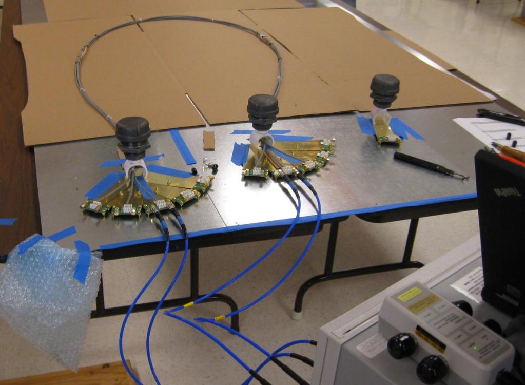
3 CommScope Test Setup UNH-IOL Test Setup 3

4 0.3 db difference between Labs 4
5 5
6 6
7 7
8 Recommended Worst Case -Special scenario 6 5 Channels 1 m 1 m F5 F4 F m F1 F m 1.67 m N5 N4 25 cm 1.67 m N1 N2 N3 Proposed Layout 8


9 The original proposal for 5 channel bundling is a 4 around the long 1 using a foam tube, but this was not stable enough A flat stick does a better job of holding the 4 in place with a tie wrap 9


10 CommScope Test Setup UNH-IOL Test Setup 10


11 Single Prototype connector 5 Pack 11

12 Prototype Connection Contact Loose from Shipping Shows Some Excess 12
13 13

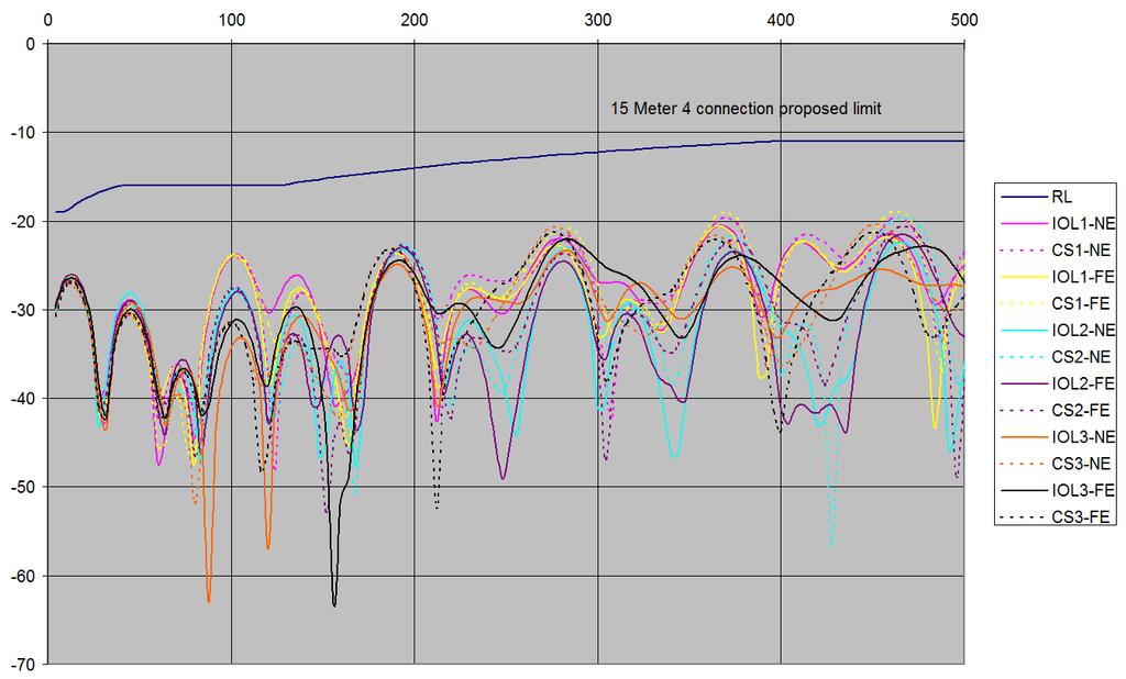
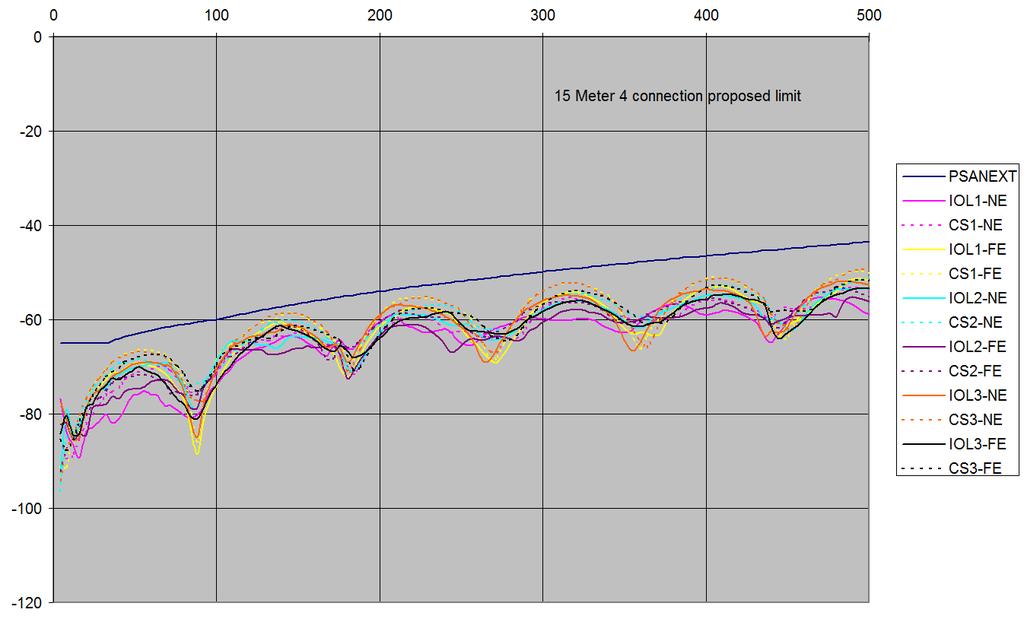
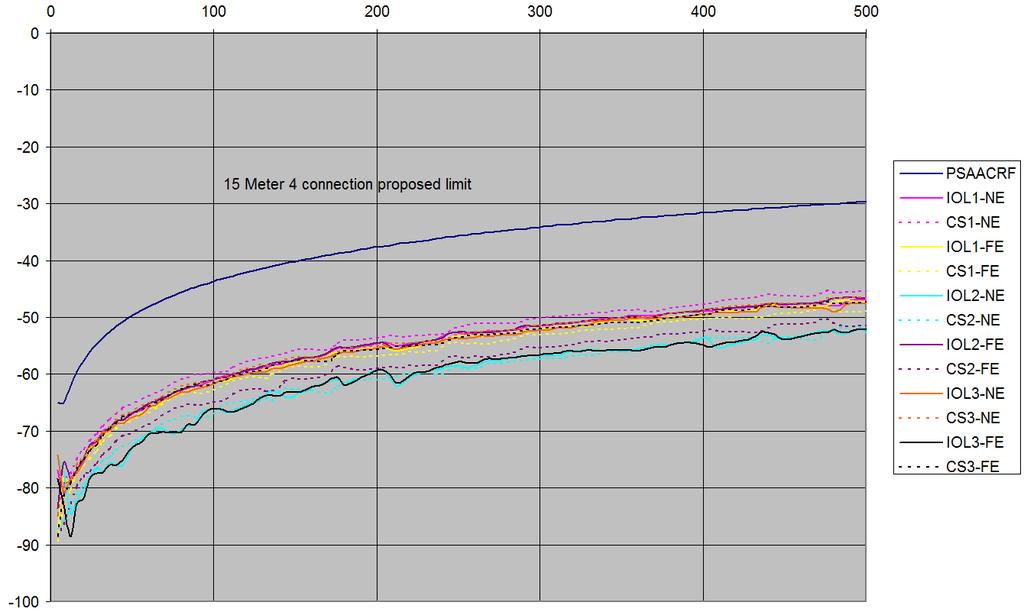
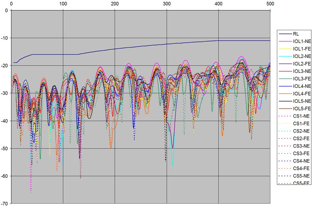
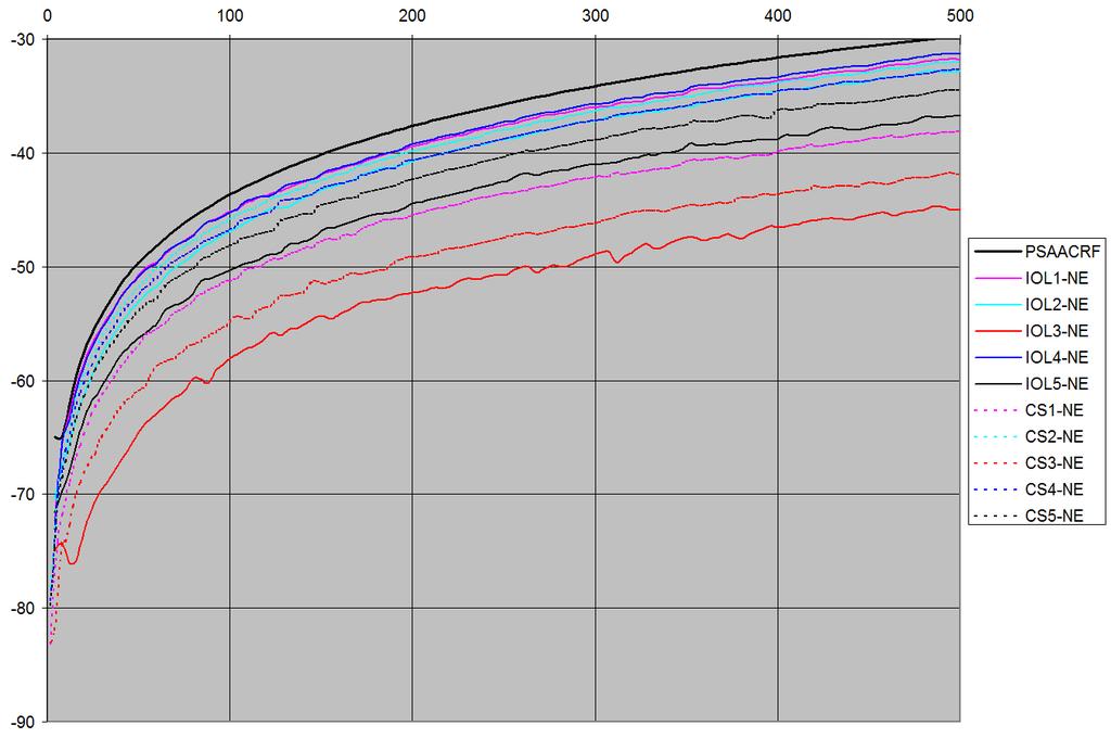
14 Channel 3 showing additional margin with additional IL to bundled section Near End 5 Channel Bundle Near End PSANEXT Comparison 14

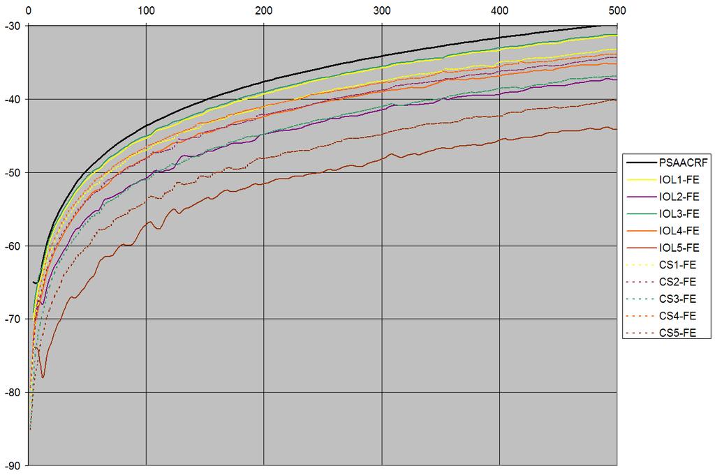
15 Prototype Connection Contact loose from shipping shows some excess Far End 5 Channel Bundle Far End PSANEXT Comparison 15
16 16
17 17
18 Key Points The 5 Channel bundling was modified from the previous proposal for improved stability in testing. Other than some minor shifts in IL and ANEXT due to a loose contact within one of the prototype connectors, comparison of results between Labs is excellent. 18
 was examined at UNH using the 5 channel bundle 4 mm height 44 mm height")
19 The 4 mm height recommendation (vs. 5 cm) was examined at UNH using the 5 channel bundle 4 mm height 44 mm height Compared: Channel 3 IL and RL Channel 3-4 Near End ANEXT 19

20 CH3 IL & 4 mm CH3 IL & 44 mm CH3-4 4 mm CH mm 20
21 Similar height comparison was done at CommScope Labs on the complete measurement set of the 3 channel bundle 4 mm 40 mm 21

22 4 mm 40 mm 22
23 Summary The stripline height of 5 cm over the ground plane is necessary for the stripline measurement because the stripline generates a strong EM field underneath where the victim device or DUT is placed for evaluation. If the DUT is moved down to the 4 mm height, the impressed field will be significantly lower and would provide much less coupling to the DUT. With this test the goal is to maximize it for a given amount of power injected onto the stripline. The network analyzer tests as we are promoting (including the 4mm height) are better suited for measuring cable and channel parameters, including alien crosstalk. These tests will not however replace EMC measurements such as stripline or BCI. 7/9/
24 Summary The primary reason to get closer to the ground is in supporting the longer channel runs to be laid out on smaller ground planes and with better proximity to network analyzer ports. The 5 channel 8 meter test requires network analyzer attachment points not only at the bundle ends, but also at the longer channel s extension end. So these points along the bundle must get close to each other for testing, and a 5 cm height risks allowing cross-coupling that can alter results. The 4 mm height captures the fields around the cables better allowing lengths to be more reasonably placed as shown. While it is true that some cable parameters are influenced by shorter distance to ground, they turn out to be inconsequential and strongly overshadowed by other factors such as the natural common mode impedance mismatching and the bundling of other channels in close proximity. In concept, there may be an optimum height, although it is a soft optimum and data so far indicates that getting closer than 4 mm begins to become sensitive to placement accuracy, while going out to 4 cm raises coupling and also begins to open up unstable antennae-like effects. 4 mm height appears to be very stable, and data so far shows consistent results with 4 cm measurements. 24
25 Conclusions Recommended test configurations demonstrated Excellent agreement between labs 4 mm reference height confirmed as superior for channel and alien measurements 25
Worst Case Alien-Near-End-Crosstalk Measurements and Analysis for IEEE 802.3bp
 Ethernet-Technology for automotive application Worst Case Alien-Near-End-Crosstalk Measurements and Analysis for data-bus-technology transmission channel UTP camera systems physical layer topology Elektronik
Belden IBDN System 10GX Enabling Technologies
 Belden IBDN System 10GX Enabling Technologies by Paul Kish Director, Systems and Standards Revision 1 November 2008 Belden Belden IBDN System 10GX Enabling Technologies 1/17 Introduction The IEEE 802.3an
Belden IBDN System 10GX The next level of cabling performance
 Belden IBDN System 10GX The next level of cabling performance by Paul Kish Director Belden IBDN Systems and Standards Introduction There is a new standard under development in the IEEE 2.3an task force
Practical De-embedding for Gigabit fixture. Ben Chia Senior Signal Integrity Consultant 5/17/2011
 Practical De-embedding for Gigabit fixture Ben Chia Senior Signal Integrity Consultant 5/17/2011 Topics Why De-Embedding/Embedding? De-embedding in Time Domain De-embedding in Frequency Domain De-embedding
Keysight Technologies Method of Implementation (MOI) for BroadR-Reach Link Segment Tests Using E5071C ENA Option TDR
 for BroadR-Reach Link Segment Tests Using E5071C ENA Option TDR") Revision 2.00 August 28, 2014 BroadR-Reach Link Segment Keysight Technologies Method of Implementation (MOI) for BroadR-Reach Link Segment Tests Using E5071C ENA Option TDR 1 Table of Contents 1. Revision
Revision 2.00 August 28, 2014 BroadR-Reach Link Segment Keysight Technologies Method of Implementation (MOI) for BroadR-Reach Link Segment Tests Using E5071C ENA Option TDR 1 Table of Contents 1. Revision
Sunlight Supply, Inc.
 FCC Part 18 Subpart C Consumer For RF Lighting Equipment Electromagnetic Compatibility Test Report Sunlight Supply, Inc. Etelligent Compatible Ballast - olt July 19, 2017 Tests Conducted by:, LLC 20811
Immunity testing example using Tekbox TEM Cells
 1 Introduction A customer asked us to solve an immunity issue of a corner light. The device failed BCI testing in the test house at frequencies in the 300 MHz to 400 MHz range. The failure mode was flickering
Challenges for testing 10GBASE-T
 Challenges for testing 10GBASE-T Adrian Young Customer Support Manager adrian.young@flukenetworks.com Check list Category 6A component compliant connector Category 6A compliant cable Perfect terminations
Installation Effects Upon Alien Crosstalk and Equal Level Far End Crosstalk
 Installation Effects Upon Alien Crosstalk and Equal Level Far End Crosstalk Paul Vanderlaan Product Development Engineer Belden Presented at BICSI January 20, 1999 Introduction New Parameters involving
Sensoray. Model 819. Tests Conducted by: ElectroMagnetic Investigations, LLC. May 10, 2013
 European Union (EU) Council Directive 2004/108/EC Electromagnetic Compatibility (EMC) and FCC Part 15 Subpart B Class B Test Report for Information Technology Equipment Sensoray Model 819 May 10, 2013
Alien Crosstalk measurement limitations at low frequencies (1 MHz to ~ 10 MHz)
") Alien Crosstalk measurement limitations at low frequencies (1 MHz to ~ 10 MHz) Prepared for IEEE802.3an 10GBase-T task group Henriecus ( Henri or Riekus ) Koeman Fluke Networks 1 Alien crosstalk Henriecus
Alien Crosstalk measurement limitations at low frequencies (1 MHz to ~ 10 MHz) Prepared for IEEE802.3an 10GBase-T task group Henriecus ( Henri or Riekus ) Koeman Fluke Networks 1 Alien crosstalk Henriecus
Test result 1. Conducted emission EN 55022: A1:2007 EA 3 passed 2. Radiated emission <1GHz (others)
") SHARP EMC Testing Laboratory Test Report No.: 11/250-02 page TR-2 of TR-13 5 SUMMARY OF TEST RESULTS Emission testing No. Item Test procedure Page code Number of pages Test result 1. Conducted emission
SHARP EMC Testing Laboratory Test Report No.: 11/250-02 page TR-2 of TR-13 5 SUMMARY OF TEST RESULTS Emission testing No. Item Test procedure Page code Number of pages Test result 1. Conducted emission
What really changes with Category 6
 1 What really changes with Category 6 Category 6, the standard recently completed by TIA/EIA, represents an important accomplishment for the telecommunications industry. Find out which are the actual differences
COHERENCE ONE PREAMPLIFIER
 COHERENCE ONE PREAMPLIFIER OWNER S MANUAL TABLE OF CONTENTS Introduction Features Unpacking Instructions Installation Phono Cartridge Loading Basic Troubleshooting Technical Specifications Introduction
EMC Test Report. 850 Kacena Road Hiawatha, IA 52233
 EMC Client: EUT: Crystal Group 850 Kacena Road Hiawatha, IA 52233 Model RS112 No.: R20140819-21 Approved By: Nic S. Johnson, NCE EMC Test Engineering Manager/Technical Manager inarte Certified EMC Engineer
R&S AMU-Z7 Analog I/Q Combiner Technical Information
 R&S AMU-Z7 Analog I/Q Combiner Technical Information 1415.7335.92 01 Test & Measurement Technical Information 2009 Rohde & Schwarz GmbH & Co. KG 81671 Munich, Germany Printed in Germany Subject to change
Measurement Accuracy of the ZVK Vector Network Analyzer
 Product: ZVK Measurement Accuracy of the ZVK Vector Network Analyzer Measurement deviations due to systematic errors of a network analysis system can be drastically reduced by an appropriate system error
Smart. Connected. Energy-Friendly.
 www.silabs.com Smart. Connected. Energy-Friendly. Miniaturizing IoT Designs Tom Nordman, Pasi Rahikkala This whitepaper explores the challenges that come with designing connected devices into increasingly
FCC PART 15 CLASS B MEASUREMENT AND TEST REPORT. Tritech Technology Ltd.
 FCC PART 15 CLASS B MEASUREMENT AND TEST REPORT For Tritech Technology Ltd. Unit 8B,Chung pont Commercial Building No.300 Hennessy Road, Wanchai, HongKong Model: 0-545-24967-8, 0-545-24986-4 Report Type:
DUKE 2. Owners manual
 DUKE 2 Owners manual 1 Table of contents Introduction Marten Philosophy Unpacking Quick Setup Connecting the loudspeakers 2 3 3 4 4 5 Choosing cables Connections Burn-in Room Acoustics Positioning 6 6
Boosting Performance Oscilloscope Versatility, Scalability
 Boosting Performance Oscilloscope Versatility, Scalability Rising data communication rates are driving the need for very high-bandwidth real-time oscilloscopes in the range of 60-70 GHz. These instruments
500W ERP SYSTEM CONFIGURATION
 500W ERP SYSTEM CONFIGURATION INTENDED USE i. The various pieces of equipment in this document are only for use permanently at a predefined location with a license or authorisation from the radio spectrum
Measuring RL on Short Cables: A Detailed Approach
 Measuring on Short Cables: A Detailed Approach Overview In the 1990s, a new method of testing return loss revolutionized the fiber optics industry. Requiring no mandrels or matching gel to measure the
10 Mb/s Single Twisted Pair Ethernet Preliminary Cable Properties Steffen Graber Pepperl+Fuchs
 10 Mb/s Single Twisted Pair Ethernet Preliminary Cable Properties Steffen Graber Pepperl+Fuchs IEEE802.3 10 Mb/s Single Twisted Pair Ethernet Study Group 9/8/2016 1 Overview Cable Properties Cable Measurements
ANSI C63.4 and CISPR 22-Harmony
 ANSI C63.4 and CISPR 22-Harmony at Last? Donald N. Heirman Lucent Technologies, Bell Laboratories Innovations Holmdel, New Jersey 07738 USA Abstract: This paper compares the most prevalent emission measurement
Agilent 83437A Broadband Light Source Agilent 83438A Erbium ASE Source
 Agilent 83437A Agilent 83438A Erbium ASE Source Product Overview H Incoherent light sources for single-mode component and sub-system characterization The Technology 2 The Agilent Technologies 83437A (BBLS)
SMART Height Adjustable Wall Mount (HAWM-UX/UF) Integration and Cabling Guide. For SMART Board 600 and 800 interactive whiteboard projector systems
 Integration and Cabling Guide. For SMART Board 600 and 800 interactive whiteboard projector systems") SMART Height Adjustable Wall Mount (HAWM-UX/UF) Integration and Cabling Guide For SMART Board 600 and 800 interactive whiteboard projector systems Product Registration If you register your SMART product,
SMART Height Adjustable Wall Mount (HAWM-UX/UF) Integration and Cabling Guide For SMART Board 600 and 800 interactive whiteboard projector systems Product Registration If you register your SMART product,
Selecting Cables for Power over Ethernet
 Hitachi Cable America Inc. Selecting Cables for Power over Ethernet Factors to Consider when Selecting the Appropriate Cable 8/12/217 Ratio of Power Dissipated vs 1 Power over Ethernet Standards and applications
The current state of multimode OTDR and Light Source and Power Meter (LSPM) Insertion Loss (IL) testing is as follows:
 Insertion Loss (IL) testing is as follows:") APPLICATION NOTE Meeting the Encircled Flux Launch Standard Scope: Guidance on how to test to the Encircled Flux (EF) multimode launch standard using existing optical test equipment and the Optronics Encircled
APPLICATION NOTE Meeting the Encircled Flux Launch Standard Scope: Guidance on how to test to the Encircled Flux (EF) multimode launch standard using existing optical test equipment and the Optronics Encircled
MAX2660/MAX2661/MAX2663/MAX2671 Evaluation Kits
 9-382; Rev ; 9/99 MAX2660/MAX266/MAX2663/MAX267 General Description The MAX2660/MAX266/MAX2663/MAX267 evaluation kits simplify evaluation of the MAX2660/MAX266/ MAX2663/MAX267 upconverter s. They enable
APM CALIBRATION PROCEDURE Rev. A June 3, 2015
 APM CALIBRATION PROCEDURE Rev. A June 3, 2015 Calibration of the APM allows system parameters such as coupler coupling values, interconnecting cable losses and system feeder losses to be programmed into
THE EFFECT OF PERFORMANCE STAGES ON SUBWOOFER POLAR AND FREQUENCY RESPONSES
 THE EFFECT OF PERFORMANCE STAGES ON SUBWOOFER POLAR AND FREQUENCY RESPONSES AJ Hill Department of Electronics, Computing & Mathematics, University of Derby, UK J Paul Department of Electronics, Computing
SCSI Cable Characterization Methodology and Systems from GigaTest Labs
 lide - 1 CI Cable Characterization Methodology and ystems from GigaTest Labs 134. Wolfe Rd unnyvale, CA 94086 408-524-2700 www.gigatest.com lide - 2 Overview Methodology summary Fixturing Instrumentation
Application Note. 3G SDI Evaluation Board. Revision Date: July 2, 2009
 3G SDI Evaluation Board Revision Date: July 2, 2009 Copyrights and Trademarks Copyright 2009 Samtec, Inc. Copyright 2009 Brioconcept Consulting Developed in collaboration between Samtec, Inc Brioconcept
BIRD 2. Owners manual MADE IN SWEDEN
 BIRD 2 Owners manual 1 MADE IN SWEDEN Table of contents Introduction Marten Philosophy Unpacking Quick Setup Connecting the loudspeakers 2 3 3 4 4 5 Choosing cables Connections Burn-in Room Acoustics Positioning
GT Dual-Row Nano Vertical SMT High Speed Characterization Report For Differential Data Applications
 GT-16-95 Dual-Row Nano Vertical SMT For Differential Data Applications 891-011-15S Vertical SMT PCB 891-001-15P Cable Mount Revision History Rev Date Approved Description A 6/3/2016 R. Ghiselli/D. Armani
De-embedding Gigaprobes Using Time Domain Gating with the LeCroy SPARQ
 De-embedding Gigaprobes Using Time Domain Gating with the LeCroy SPARQ Dr. Alan Blankman, Product Manager Summary Differential S-parameters can be measured using the Gigaprobe DVT30-1mm differential TDR
Class E A / Cat.6A Screened Coupler
 Class E A / Cat.6A Screened Coupler Patented Qualified Class E A / Cat.6A (500MHz) of ANSI/TIA-568-C.2 IEC 60603-7-51 AMD 2,Class E A CENELEC EN 50173-1 Specification Specification: Qualified Screened
Senior Project Manager / AEO
 Kenny Liao 2018.12.18&20 Senior Project Manager / AEO Measurement Demo Prepare instrument for measurement Calibration Fixture removal Conclusion What next? Future trends Resources Acquire channel data
Everything you always wanted to know about HDBaseT*
 Everything you always wanted to know about HDBaseT* * But were afraid to ask Bill Lauby Sr. Product Manager Leviton Network Solutions Speaker Bio Bill Lauby, Sr. Product Manager Leviton Network Solutions
By Jim Norton Bird Technologies Group Applications Engineer
 Introduction The masking effect of cable loss may cause your antenna to "appear" to perform more efficiently than is actually the case. In fact, it is possible to measure apparently acceptable or return
HDBaseT Installation Guide
 Installation Guide This document provides the best practices for installing Ethernet cable with setups. We strongly recommend to use ATEN certified cable (2L-2910) to provide best performance and to guarantee
ENGINEERING COMMITTEE Interface Practices Subcommittee AMERICAN NATIONAL STANDARD ANSI/SCTE
 ENGINEERING COMMITTEE Interface Practices Subcommittee AMERICAN NATIONAL STANDARD ANSI/SCTE 48-3 2011 Test Procedure for Measuring Shielding Effectiveness of Braided Coaxial Drop Cable Using the GTEM Cell
PiMPro Portable Analyzer PiMPro Classic 1821
 DATA SHEET Highly accurate portable PIM Analyzer provides two 40 watt carriers (40W x 2), with -125 dbm sensitivity all in a less than 36 pound carry-on size case Instantaneous Measurement Modes for PIM
2.1 Kit Contents 2.2 Elements needed from the FIST installation kit 2.3 Tools 2.4 Cable preparation table
 FIST-GCO2-F INSTALLATION INSTRUCTION GCO2-FC GCO2-FD Content 1 Introduction 2 General 2.1 Kit Contents 2.2 Elements needed from the FIST installation kit 2.3 Tools 2.4 Cable preparation table 3 Installation
RF Characterization Report
 BNC7T-J-P-xx-ST-EMI BNC7T-J-P-xx-RD-BH1 BNC7T-J-P-xx-ST-TH1 BNC7T-J-P-xx-ST-TH2D BNC7T-J-P-xx-RA-BH2D Mated with: RF179-79SP1-74BJ1-0300 Description: 75 Ohm BNC Board Mount Jacks Samtec, Inc. 2005 All
PEP-I1 RF Feedback System Simulation
 SLAC-PUB-10378 PEP-I1 RF Feedback System Simulation Richard Tighe SLAC A model containing the fundamental impedance of the PEP- = I1 cavity along with the longitudinal beam dynamics and feedback system
MPI Cable Selection Guide
 MPI Cable Selection Guide MPI engineers focus to provide on optimal cable solutions taking into account a number of requirements specific for wafer-level measurement systems: optimal cable length, cable
Dish Diversity Switch
 www.travel-vision.com Dish Diversity Switch INSTALLATION & USER S MANUAL Version 3.1 October 2013 PREFACE The information in this Installation and User s Manual is subject to change in order to improve
CTP10 KEY FEATURES SPEC SHEET COMPONENT TEST PLATFORM
 COMPONENT TEST PLATFORM Efficiently test passive components in 24/7 operation. Perform single sweep insertion loss and return loss measurements with unprecedented dynamic range, speed and resolution. SPEC
GT Dual-Row Nano Vertical Thru-Hole High Speed Characterization Report For Differential Data Applications
 GT-16-97 Dual-Row Nano Vertical Thru-Hole For Differential Data Applications 891-007-15S Vertical Thru-Hole PCB 891-001-15P Cable Mount Revision History Rev Date Approved Description A 8/31/2016 R. Ghiselli/G.
EMC TEST REPORT. Product : Digital Camcorder Model No. : SCD5000. SAMSUNG ELECTRONICS Co., Ltd. EMC Test Laboratory. Project No.
 Page 1 of 17 EMC TEST REPORT Project No. :LBE031059 Product : Digital Camcorder Model No. : SCD5000 Date of test : May 7 ~ 9, 2003 Issued Date : May 9, 2003 Tested by: Jay Yong, PARK / Test Engineer Reviewed
M2 Antenna Systems, Inc. Model No: 23CM35
 M2 Antenna Systems, Inc. Model No: 23CM35 SPECIFICATIONS: Model... 23CM35 Frequency Range... 1250 To 1300 MHz *Gain... 20.94 dbi Front to back... 25 db Typical Beamwidth... E=17 H=18 Feed type... Folded
Robert Burén. Product Manager. Nexans Cabling Solutions. 10G Solutions
 Robert Burén Product Manager 10G Solutions Nexans Cabling Solutions 1 10 Gigabit Ethernet.Performance 30 GByte can be transmitted within 24 seconds Example: MRI-scan size is 30GB as average A memory device
CONTENTS 6.2 TEST SET-UP...16
 CONTENTS 1. GENERAL INFORMATION...3 2. INTRODUCTION...4 3. PRODUCT INFORMATION...5 3.1 DESCRIPTION OF EUT...5 3.2 SUPPORT EQUIPMENT / CABLES USED...6 3.3 MODIFICATION ITEM(S)...6 4. DESCRIPTION OF TESTS...7
Cable Calibration Function for the 2400B/C and 2500A/B Series Microwave Signal Generators. Technical Brief
 Cable Calibration Function for the 2400B/C and 2500A/B Series Microwave Signal Generators Technical Brief Quickly and easily apply a level correction table to compensate for external losses or power variations
Do you know if your Cat. 6 patch cord has been tested according to standards?
 White Paper 02. Juli 2002 Andreas Clauser Hauptsitz Binzstrasse 31 CH-8622 Wetzikon Tel +41 1 933 8375 Fax +41 1 930 49 41 Internet www.rdm.com Do you know if your Cat. 6 patch cord has been tested according
ASP-FIBRS1 User Manual
 ASP-FIBRS1 HDMI Single Fiber Extender with Serial and IR User Manual Manual Number: 100823 Safety and Notice The ASP-FIBRS1 HDMI Extender over 1 fiber with serial and IR have been tested for conformance
bel canto SEP2 Single Ended Triode Tube Preamplifier User's Guide and Operating Information
 bel canto SEP2 Single Ended Triode Tube Preamplifier User's Guide and Operating Information Bel Canto Design 212 Third Avenue North, Suite 274 Minneapolis, MN 55401 USA Phone: 612 317.4550 Fax: 612.359.9358
White Paper. Cabling for Success with DXLink TM Author: Curry Kinyon Co-Author: Jeff Howes Co-Author: Ann Yanecek
 Cabling for Success with DXLink TM Author: Curry Kinyon Co-Author: Jeff Howes Co-Author: Ann Yanecek Page 1 AMX Cabling for Success with DXLink TM V 2.0 10.2012 Table of Contents EXECUTIVE SUMMARY... 3
508 Phono Preamplifier. Boulder Amplifiers, Inc. 255 S. Taylor Ave. Louisville, CO (303) /1/2018 Rev. 1.
 /1/2018 Rev. 1.") 508 Phono Preamplifier 6/1/2018 Rev. 1.0 P/N: 91053 Boulder Amplifiers, Inc. 255 S. Taylor Ave. Louisville, CO 80027 (303) 449-8220 www.boulderamp.com About About Boulder Amplifiers, Inc. Boulder was founded
508 Phono Preamplifier 6/1/2018 Rev. 1.0 P/N: 91053 Boulder Amplifiers, Inc. 255 S. Taylor Ave. Louisville, CO 80027 (303) 449-8220 www.boulderamp.com About About Boulder Amplifiers, Inc. Boulder was founded
Agilent 86120B, 86120C, 86122A Multi-Wavelength Meters Technical Specifications
 Agilent 86120B, 86120C, 86122A Multi-Wavelength Meters Technical Specifications March 2006 Agilent multi-wavelength meters are Michelson interferometer-based instruments that measure wavelength and optical
32 Channel CPCI Board User Manual
 0 Sections Page 1.0 Introduction 1 2.0 Unpacking and Inspection 1 3.0 Hardware Configuration 1 4.0 Board Installation 5 5.0 I/O Connections and the Front Panel 5 5.1 Front Panel Layout 5 5.2 Input and
OP940. Insertion Loss & Return Loss Meter Instruction Manual. (Also supports the OP725 Integration)
") Insertion Loss & Return Loss Meter Instruction Manual (Also supports the OP725 Integration) www.optotest.com 1.805.987.1700 Contacting OptoTest Corporation 1.805.987.1700 (7:30 a.m. to 5 p.m. PST) www.optotest.com
Insertion Loss & Return Loss Meter Instruction Manual (Also supports the OP725 Integration) www.optotest.com 1.805.987.1700 Contacting OptoTest Corporation 1.805.987.1700 (7:30 a.m. to 5 p.m. PST) www.optotest.com
UC Copper / Fibre summary on USPs. Zoran Borcic, Axel Koplev
 UC Copper / Fibre summary on USPs Zoran Borcic, Axel Koplev Draka UC Cable Key Elements UC Copper Range Shielded solutions Focus on Cat. 6 A / 7/ 7 A Prepare for Cat.8 / 40G Patent based design Cat. 6
Calibrating attenuators using the 9640A RF Reference
 Calibrating attenuators using the 9640A RF Reference Application Note The precision, continuously variable attenuator within the 9640A can be used as a reference in the calibration of other attenuators,
Copyright 2018 Xi an NovaStar Tech Co., Ltd. All Rights Reserved. No part of this document may be copied, reproduced, extracted or transmitted in any
 MRV366 Receiving Card Document Version: Document Number: V1.0.1 NS110100658 Copyright 2018 Xi an NovaStar Tech Co., Ltd. All Rights Reserved. No part of this document may be copied, reproduced, extracted
Hewlett Packard 3577A 5Hz MHz Network Analyzer Specifications SOURCE
 Established 1981 Advanced Test Equipment Rentals www.atecorp.com 800-404-ATEC (2832) Frequency Hewlett Packard 3577A 5Hz - 200 MHz Network Analyzer Specifications SOURCE 5 Hz - 200 MHz 0.001 Hz Amplitude
GigaSPEED X10D F/UTP. SYSTIMAX solutions
 GigaSPEED X10D F/UTP SYSTIMAX solutions Contents Introduction 3 SYSTIMAX GigaSPEED X10D F/UTP channel performance 3 SYSTIMAX GigaSPEED X10D 91 series F/UTP cable 5 SYSTIMAX GigaSPEED X10D G10FP F/UTP 6
RF Signal Capture & Playback Simple Operation Guide
 User Guide RF Signal Capture & Playback Simple Operation Guide Signal Analyzer and Built-in Vector Signal Generator Option MS2690A Series MS2830A (3.6/6.0/13.5 GHz Model) MS2840A (3.6/6.0 GHz Model) This
EVLA Fiber Selection Critical Design Review
 EVLA Fiber Selection Critical Design Review December 5, 2001 SJD/TAB 1 Fiber Selection CDR Decision about what fiber to install Select cable Jan 2002 Order cable Jan 2002 Receive cable May 2002 Start installation
R&S ZN-Z32/-Z33 Automatic In-line Calibration Modules Ensuring high accuracy with thermal vacuum testing and multiport measurements
 R&S ZN-Z32/-Z33 Automatic In-line Calibration Modules Ensuring high accuracy with thermal vacuum testing and multiport measurements Product Brochure Version 01.01 R&S ZN-Z32/-Z33 Automatic In-Line Calibration
PiMPro Rack Mount Analyzer
 DATA SHEET Highly accurate 19 inch rack mount PIM Analyzer provides two 40 watt carriers (40W x 2), with -125 dbm sensitivity all in a less than 36 pound carry-on size case Instantaneous Measurement Modes
Seal Kits for BUDI Enclosures
 Description BUDI is a product range of compact, wall mountable fiber enclosures for indoor and outdoor use. They are specifically designed for fast deployment and easy customer connection. The FIST management
Product Introduction. Duplexer Box MN2555A. Signal Analyzer MS2830A. Ver.1.0
 Product Introduction Duplexer Box MN2555A Signal Analyzer MS2830A Ver.1.0 Duplexer Box MN2555A Duplexer Box MN2555A Connecting MN2555A, Signal Analyzer MS2830A, and USB Power Sensor *The shape of the accessory
OPTICAL POWER METER WITH SMART DETECTOR HEAD
 OPTICAL POWER METER WITH SMART DETECTOR HEAD Features Fast response (over 1000 readouts/s) Wavelengths: 440 to 900 nm for visible (VIS) and 800 to 1700 nm for infrared (IR) NIST traceable Built-in attenuator
Cabling and Completing Assembly of the Cisco TelePresence System 1000
 CHAPTER 5 Cabling and Completing Assembly of the Cisco TelePresence System 1000 Revised: April 5, 2010, Introduction This chapter describes how to set up and connect the cables, microphone and Cisco Unified
PCIe: EYE DIAGRAM ANALYSIS IN HYPERLYNX
 PCIe: EYE DIAGRAM ANALYSIS IN HYPERLYNX w w w. m e n t o r. c o m PCIe: Eye Diagram Analysis in HyperLynx PCI Express Tutorial This PCI Express tutorial will walk you through time-domain eye diagram analysis
Microwave Counter, Power Meter and DVM in One Portable Package
 Agilent 53140 Series Microwave Counter, Power Meter and DVM in One Portable Package Product Overview Everything you need for the installation and maintenance of microwave links: A choice of frequency counter
IEEE 802.3af Power via MDI Standard Compliant Mid-Span Insertion Solution. Presented by PowerDsine: David Pincu -
 IEEE 802.3af Power via MDI Standard Compliant Mid-Span Insertion Solution Presented by PowerDsine: David Pincu - davidp@powerdsine.com Objectives! Investigate the Channel /Link options! Identify the requirements
SECTION COMMUNICATIONS HORIZONTAL CABLING
 (NOTE TO DESIGNER: These Specifications are basic minimum criteria to be met in preparing the final specifications for this section, which is the responsibility of the Designer.) PART 1 - GENERAL 1.1 SECTION
384A Adapter Installation Instructions
 Instruction Sheet 860237684 Issue 9, October 2012 SYSTIMAX Solutions 384A Adapter Installation Instructions General The 384A adapter (Figure 1) is a broadband video adapter that provides connectivity to
Switching Solutions for Multi-Channel High Speed Serial Port Testing
 Switching Solutions for Multi-Channel High Speed Serial Port Testing Application Note by Robert Waldeck VP Business Development, ASCOR Switching The instruments used in High Speed Serial Port testing are
Distribution Unit. User Guide
 Distribution Unit User Guide CONTENTS 1. Introduction Page 2 2. Technical Specifications Page 3 3. Installation 3.1 Inspection and un-packing Page 4 3.2 Operating environment Page 4 3.3 Power requirements
Copper Cabling Troubleshooting Handbook
 NETWORKSUPERVISION Copper Cabling Troubleshooting Handbook NETWORKSUPERVISION Table of Contents Introduction 2 Troubleshooting Basics 3 Link Models 4 The automated DTX Series diagnostics 5 Causes of Cabling
PRJTPFL inch PRJTPFL inch PRJTPFL inch. Fixed Wall Mount Projector Screen. Universal Home/Office Projector Viewing Display
 PRJTPFL102-100 - inch PRJTPFL112-110 - inch PRJTPFL122-120 - inch Fixed Wall Mount Projector Screen Universal Home/Office Projector Viewing Display Be sure to read this manual before use so you will know
DEEPFRAME BASIC KIT- USER MANUAL VERSION ORIGINAL USER MANUAL
 DEEPFRAME BASIC KIT- USER MANUAL VERSION 1.3 - ORIGINAL USER MANUAL It is important to read this manual before using the DeepFrame, and to follow advices and instructions on safety, operation and general
Advanced Test Equipment Rentals ATEC (2832)
") E stablished 1981 Advanced Test Equipment Rentals www.atecorp.com 800-404-ATEC (2832) Technical Datasheet Scalar Network Analyzer Model 8003-10 MHz to 40 GHz The Giga-tronics Model 8003 Precision Scalar
E stablished 1981 Advanced Test Equipment Rentals www.atecorp.com 800-404-ATEC (2832) Technical Datasheet Scalar Network Analyzer Model 8003-10 MHz to 40 GHz The Giga-tronics Model 8003 Precision Scalar
Data Communications Competence Center
 s Data Communications Competence Center DCCC00 June 9, 00 Test Summary Active testing was performed on Berk-Tek s -pair, Category e cables. The testing demonstrates the ability of this cable to reliably
XCOM1002JE (8602JE) Optical Receiver Manual
 Optical Receiver Manual") XCOM1002JE (8602JE) Optical Receiver Manual - 2 - 1. Product Summary XCOM1002JE (8602JE) outdoor optical receiver is our latest 1GHz optical receiver. With wide range receiving optical power, high output
XCOM1002JE (8602JE) Optical Receiver Manual - 2 - 1. Product Summary XCOM1002JE (8602JE) outdoor optical receiver is our latest 1GHz optical receiver. With wide range receiving optical power, high output
IEEE 100BASE-T1 Physical Coding Sublayer Test Suite
 IEEE 100BASE-T1 Physical Coding Sublayer Test Suite Version 1.1 Author & Company Curtis Donahue, UNH-IOL Stephen Johnson, UNH-IOL Title IEEE 100BASE-T1 Physical Coding Sublayer Test Suite Version 1.1 Date
FCC PART TEST REPORT. HHC Changzhou Corp.
 FCC PART 15.249 TEST REPORT For HHC Changzhou Corp. No 61, Xinggang Road, Zhonglou District, Changzhou, Jiangsu, China, 213023 FCC ID: 2AEQWCB20HHC011 Report Type: Original Report Product Type: Control
RF Semiconductor Test AXRF RF Port Upgrade Kits
 RF Semiconductor Test AXRF RF Port Upgrade Kits 2017 Datasheet The most important thing we build is trust Overview AXRF RF Port Upgrade Kits are designed to improve and extend the capability of an existing
30 GHz Attenuator Performance and De-Embedment
 30GHz De-Embedment Application Note - Page 1 of 6 Theory of De-Embedment. Due to the need for smaller packages and higher signal integrity a vast majority of todays RF and Microwave components are utilizing
PART. Maxim Integrated Products 1
 9-646; Rev 0; /00 General Description The MAX94 evaluation kit (EV kit) is assembled with a MAX94 and the basic components necessary to evaluate the -bit analog-to-digital converter (ADC). Connectors for
The performance of a lifetime. Owner s Manual MOON 110LP v2 Phono Preamplifier
 The performance of a lifetime Owner s Manual MOON 110LP v2 Phono Preamplifier MOON by Simaudio simaudio.com Simaudio Ltd 1345 Newton Road, Boucherville, Québec J4B 5H2 CANADA Date Code: 20180831 01 INTRODUCTION
Small footprint, big advantages: how connectors enable the networks of tomorrow
 White Paper Small footprint, big advantages: how 4.3-10 connectors enable the networks of tomorrow Pedro Torres, Mobility Network Engineering July 2016 Miniature Outside Plant Plug-and-Play Solutions Contents
Gel-sealed in-line fiber optic closure
 SCIL-C Gel donut INSTALLATION INSTRUCTION TC-1363-1-IP Rev A, Oct 2017 www.commscope.com Gel-sealed in-line fiber optic closure Contents 1 General 2 Sizing and product kit information 3 Installation conditions
Test Report. Product Name: Access Point Model No.: MS-6809 FCC ID: DoC
 Test Report Product Name: Access Point Model No.: MS-6809 FCC ID: DoC Applicant : MICRO-STAR INT L Co., LTD Address : No 69, Li-De st., Jung-He City, Taipei Hsien, Taiwan, R.O.C Date of Receipt : June
R&S RSC Step Attenuator Where precise signal levels count
 Test & Measurement Product Brochure 01.00 Step Attenuator Where precise signal levels count Step Attenuator At a glance The is a switchable, mechanical step attenuator. It is available in various models