MP1100 Phono Preamplifier Owner s Manual
|
|
|
- Claribel Roberts
- 5 years ago
- Views:
Transcription


1 McIntosh Laboratory, Inc. 2 Chambers Street Binghamton, New York MP1100 Phono Preamplifier Owner s Manual Phone:
2 Important Safety Information is supplied in a separate document Important Additional Operation Information Guide Thank You Your decision to own this McIntosh MP1100 Phono Preamplifier ranks you at the very top among discriminating music listeners. You now have The Best. The McIntosh dedication to Quality, is assurance that you will receive many years of musical enjoyment from this unit. Please take a short time to read the information in this manual. We want you to be as familiar as possible with all the features and functions of your new McIntosh. Please Take A Moment The serial number, purchase date and McIntosh Dealer name are important to you for possible insurance claim or future service. The spaces below have been provided for you to record that information: Serial Number: Purchase Date: Dealer Name: Technical Assistance If at any time you have questions about your McIntosh product, contact your McIntosh Dealer who is familiar with your McIntosh equipment and any other brands that may be part of your system. If you or your Dealer wish additional help concerning a suspected problem, you can receive technical assistance for all McIntosh products at: McIntosh Laboratory, Inc. 2 Chambers Street Binghamton, New York Phone: Fax: Customer Service If it is determined that your McIntosh product is in need of repair, you can return it to your Dealer. You can also return it to the McIntosh Laboratory Service Department. For assistance on factory repair return procedure, contact the McIntosh Service Department at: McIntosh Laboratory, Inc. 2 Chambers Street Binghamton, New York Phone: Fax: Table of Contents Safety Instructions... 2 (Separate Sheet)... Important Additional Operation Information Guide Thank You and Please Take a Moment... 2 Technical Assistance and Customer Service... 2 Table of Contents... 2 General Information... 3 Connector and Cable Information... 3 Introduction... 4 Performance Features Dimensions... 6 Installation... 7 Connections: Rear Panel Connections... 8 Connecting Components... 9 Front Panel: Front Panel Displays, Controls, Push-buttons Front Panel Information Displays Modes...11 Remote Control: HR090 Remote Control Push-buttons Setup: How to Operate the Setup Mode Default Settings, Firmware Version Input Settings Rename Input Profile Store Digital Output Tube Lights Power Mode IR Sensor Factory Reset Operation: How to Operate the MP Trim Functions Mute, Trim and Output Meters USB Input and Installing Software Reset of Microprocessors Graphic Curves Rumble and Scratch Filter Curves Additional Information: Photo Specifications Packing Instruction Copyright 2016 by McIntosh Laboratory, Inc. 2
3 General Information and Connector Information General Information 1. For additional connection information, refer to the owner s manual(s) for any component(s) connected to the MP1100 Phono Preamplifier. 2. The Main AC Power going to the MP1100 and any other McIntosh Component(s) should not be applied until all the system components are connected together. Failure to do so could result in malfunctioning of some or all of the system s normal operations. When the MP1100 and other McIntosh Components are in their Standby Power Off Mode, the Microprocessor s Circuitry inside each component is active and communication is occurring between them. 3. The Balanced and Unbalanced Outputs may be used simultaneously, connected to different Preamplifiers or component recording device. 4. The MP1100 internal Analog to Digital Converter Circuitry is designed to encode 2-channel PCM (Pulse Code Modulation) Digital Signals. The Coaxial and Optical Digital Audio Outputs are for PCM Digital Signals. 5. Sound Intensity is measured in units called Decibels and db is the abbreviation. 6. When discarding the unit, comply with local rules or regulations. Batteries should never be thrown away or incinerated but disposed of in accordance with the local regulations concerning battery disposal. 7. For additional information on the MP1100 and other McIntosh Products please visit the McIntosh Web Site at Connector and Cable Information XLR Connectors Below is the Pin configuration for the XLR Balanced Output Connector on the MP1100. Refer to the diagram for connections: PIN 1: Shield/Ground PIN 2: + Output PIN 3: - Output PIN 2 PIN 1 PIN 3 Power Control (Trigger) Connectors When the MP1100 TRIGger IN Connector receives a Power Control On Signal (5 to 12 volts) it will make that signal available at the TRIGger OUT Connector to control other connected McIntosh Components. An additional connection is for controlling the illumination of the Output Meters on McIntosh PIN 1 PIN 2 PIN 3 Power Control Meter Illumination Control Ground Components. A 3.5mm stereo mini phone plug is used for connection to the Power Control (Trigger) Connectors on the MP
4 Introduction The McIntosh MP1100 Phono Preamplifier is one of the finest Phono Preamplifiers ever created and has the ability for connections to components with analog and digital inputs. The MP1100 reproduction is sonically transparent and absolutely accurate. The McIntosh Sound is The Sound of the Music Itself. Performance Features Electromagnetic Input Switching Digital Logic Circuits drive Electromagnetic Switches on Inputs and operating functions for reliable, noiseless, distortion free switching. Vacuum Tube Phono Amplification The MP1100 utilizes Vacuum Tube Amplification Circuitry for the Phono Inputs. The circuits use the latest designs providing the lowest possible noise and distortion. Fully Balanced Circuitry The MP1100 utilizes the very latest in Fully Balanced Circuitry from the Input Connectors all the way to the Output Connectors for the lowest possible noise and distortion. Moving Coil and Moving Magnet Phono Inputs The MP1100 has three precision Phono Preamplifier Circuits with unbalanced and balanced connections. They have the ability to be configured for Moving Coil or Moving Magnet Cartridges. The close tolerance resistors and capacitors used in the Equalization Circuitry provide an extremely flat frequency response. Selectable Phono Cartridge Loading Adjustable Capacitance and Resistance Loading are available for both Moving Coil and Moving Magnet Phono Cartridges. Resistance Loading is selectable from values of 25 ohms to 47,000 ohms. Capacitance Loading is selectable from values of 50 picofarads to 400 picofarads. Balanced and Unbalanced Outputs The Balanced Outputs allow connection using long cable lengths without a loss in sound quality. The MP1100 also has unbalanced Output connections for compatibility with a wide range of audio components. Rumble and Scratch Filters Selectable Rumble and Scratch Filters can improve the quality of sound when playing back older vinyl recodings. Digital Audio Outputs The Digital Outputs encode PCM Signals from the selected Input (Phono and Line). Coaxial and Optical Outputs process Digital Signals at 96kHz or 192kHz with 24-Bit resolution. The Digital Outputs have two different output level settings and the Digital Circuitry can be switched Off providing true analog only signal processing. USB Digital Audio Output The USB Digital Output provides Digital Signals at 96kHz or 192kHz with 24-Bit resolution from the selected Input. Dual Mono Design The circuitry for both channels is totally separate, physically isolated and shielded which helps to assure total channel isolation. Selectable Equalizer In addition to normal RIAA Equalization Standard, the MP1100 provides the ability to select four alternative Equalization Settings of LP, AES, NAB or 78. This helps to assure a desired tonal balance when playing a wide variety of phonograph records made before the RIAA Equalization Standard was employed. Alphanumeric Fluorescent Display The Front Panel Information Display indicates the Source Selection, Cartridge Loading, Equalizer and Setup Mode Selections. The display intensity is adjustable. Illuminated Output Meters The Illuminated Output Meters are peak responding, and indicate the output of the MP1100 Phono Preamplifier. Special Power Supply The Multi Regulated Power Supply and a special R-Core Power Transformer ensure stable noise free operation even though the power line varies. Remote Control with External Sensor Input The Remote Control provides control of the MP1100 operating functions. The External Sensor Input provides Remote Control when the MP1100 is located behind closed doors or in another room. 4
5 Introduction and Performance Features Power Control Connections The Power Control (PWR CTRL) TRIGger INput Connection provides convenient Turn-On/Off of the MP1100 when connected to a McIntosh Component with Power Control TRIGger OUT. The MP1100 TRIGger OUT Connection provides Turn-On/Off operation when connected with other McIntosh Audio Components. LED Front Panel Illumination The even Illumination of the Front Panel is accomplished by multiple extra long life Light Emitting Diodes (LEDs) arranged with a special orientation. Glass Front Panel and Super Mirror Chassis Finish The famous McIntosh Illuminated Glass Front Panel and the Lower Chassis are Stainless Steel with a Mirror Finish. The Upper Chassis and Top Cover is hairline brushed black Titanium Stainless Steel Finish. This will ensure the pristine beauty of the MP1100 will be retained for many years to come. 5
6 Dimensions Dimensions The following dimensions can assist in determining the best location for your MP1100. There is additional information on the next page pertaining to installing the MP1100 into cabinets. Front View of the MP /2" 44.4cm 5-3/8" 13.7cm 6" 15.2cm Side View of the MP /8" 40.3cm 14-1/2" 36.8cm Rear View of the MP /8" 43.5cm 3/16" 0.48cm 4-13/16" 12.22cm 4-5/8" 11.8cm 13/16" 2.1cm 10-9/16" 26.8cm 1-15/16" 4.9cm 2" 5.1cm 13-1/4" 33.7cm 6
7 Installation Installation The MP1100 can be placed upright on a table or shelf, standing on its four feet. It also can be custom installed in a piece of furniture or cabinet of your choice. The four feet may be removed from the bottom of the MP1100 when it is custom installed as outlined below. The four feet together with the mounting screws should be retained for possible future use if the MP1100 is removed from the custom installation and used free standing. The required panel cutout, ventilation cutout and unit dimensions are shown. Always provide adequate ventilation for your MP1100. Cool operation ensures the longest possible operating life for any electronic instrument. Do not install the MP1100 directly above a heat generating component such as a high powered amplifier. If all the components are installed in a single cabinet, a quiet running ventilation fan can be a definite asset in maintaining all the system components at the coolest possible operating temperature. A custom cabinet installation should provide the following minimum spacing dimensions for cool operation. Allow at least 6 inches (15.2cm) above the top, 2 inches (5.1cm) below the bottom and 1 inch (2.5cm) on each side of the Preamplifier, so that airflow is not obstructed. Allow 18-1/2 inches (47.0m) depth behind the front panel. Allow 1-7/16 inch (3.7cm) in front of the mounting panel for knob clearance. Be sure to cut out a ventilation hole in the mounting shelf according to the dimensions in the drawing. MP1100 Front Panel Custom Cabinet Cutout MP1100 Side View in Custom Cabinet MP1100 Bottom View in Custom Cabinet Cabinet Front Panel Cabinet Front Panel Opening for Ventilation Support Shelf 15-1/16" 38.3cm 17-3/16" 43.66cm Opening for Ventilation 6" 15.2cm Cutout Opening for Ventilation Cutout Opening for Custom Mounting Cutout Opening for Ventilation 2-7/8" 7.3cm 8-1/8" 23.2cm 13-1/8" 33.3cm 10-3/4" 27.3cm Chassis Spacers 15-1/16" 39.6cm Note: Center the cutout Horizontally on the unit. For purposes of clarity, the above illustration is not drawn to scale. 1-1/8" 2.9cm 12-5/16" 31.3cm 7
8 Rear Panel Connections Rear Panel Connections The identification of Rear Panel Connections for the MP1100 Phono Preamplifier is located on a separate folded sheet contained in the Owner s Manual Packet. Refer to separate sheet Mc1B for the Rear Panel Connections. MP1100 Phono Preamplifer Rear Panel 8
9 Connecting Components Connecting Components The MP1100 has the ability to automatically switch power On/Off from Components via the PWR CTRL (Power Control) TRIGger connections. Follow the connection instructions below, together with the MP1100 Input/Output/Control Connection Diagram located on a separate folded sheet Mc1A contained in the Owner s Manual Packet. The connections are an example of a typical audio system. Your system may vary from this, however the actual components would be connected in a similar manner. For additional information refer to Connector and Cable Information on page 3. Power Control (Trigger) Connections: 1. Connect a Control Cable from the MP1100 Power Control TRIGger Out Jack to the Power Control In on the Turntable Optionally, connect a Control Cable from the Turntable 1 Power Control Out Jack to the Power Control In on the Turntable Optionally, connect a Control Cable from the Main Audio Preamplifier Power Control Out to the MP1100 Power Control TRIGger IN. Note: This optional Power Control Connection will allow the MP1100 to automatically switch ON and OFF when the Main Audio Preamplifier is On or Off. 4. Connect any additional Components in a similar manner, as outlined in steps 1 and 2. Audio Connections: 5. Connect Audio Cables from the MP1100 PHONO 1 INPUT Jacks (Left and Right) to Turntable 1 (Left and Right) Output Jacks. Note: If Turntable 1 has Balanced XLR Output Connectors and has a Phono Cartridge installed (with Balanced Output Connections), connect XLR Audio Cables to the MP1100 PHONO 3 INPUT BALanced Connectors. 6. Optionally, connect Audio Cables from the MP1100 PHONO 2 INPUT Jacks (Left and Right) to Turntable 2 (Left and Right) Output Jacks. Note: If Turntable 2 has Balanced XLR Output Connectors and has a Phono Cartridge installed (with Balanced Output Connections), connect XLR Audio Cables to the MP1100 PHONO 3 INPUT BALanced Connectors. 7. Connect an additional Turntable in a similar manner, as outlined in steps 5 and Connect an Audio Cable from the MP1100 LINE 1 INPUT (Left and Right) Jacks to the Integrated Amplifier REC Output Jacks. Note: If the component has Balanced Output Connections use the MP1100 LINE 2 BALanced INPUT. 9. Connect any additional Components in a similar manner, as outlined in step 8. Optional USB Connection: 10. Connect a USB cable with (Type A to Type B) connectors from the MP1100 USB DIGITAL OUTPUT connector to an available USB connector on the computer. Analog Output Connection: 11. Connect XLR audio cables from the MP1100 BALanced OUTPUT (Left and Right) to the Analog only Preamplifier Balanced Input 5 (Left and Right). Note: If the Preamplifier has Unbalanced Inputs then connect the MP1100 unbalanced Output Jacks to the Preamplifier unbalanced Input Jacks. Optional Digital Output Connection: 12. Connect a Digital Coaxial Cable from the MP1100 COAXial DIGITAL AUDIO OUTPUT Jack to the Digital only Preamplifier Digital Audio Input Coaxial 2 Jack. Note: If the Preamplifier has Optical Inputs then connect the MP1100 Optical Output Connector to the Preamplifier Optical Input Connector. Ground Connections: 13. Connect the Ground Cable coming from the Turntable(s) to the MP1100 TURNTABLE GROUND Binding Post(s). AC Power Cord Connections: 14. Connect the MP1100 to a live AC Outlet using the supplied Power Supply Cord. 9
10 Front Panel Displays, Controls and Push-buttons INPUT Control used to select a source for listening and recording. The control is also used to enter the TRIM or SETUP Modes and select the various functions Meter indicates the Left Channel Output of the Preamplifier IR Sensor receives commands from a Remote Control Meter indicates the Right Channel Output of the Preamplifier LOAD Control used to select the Resistance value in Ohms and Capacitance value in Picofarads that is added to the Input Signal Path for a flat Frequency Response from the connected MM or MC Phono Cartridge MUTE Push-button mutes the audio from the Loudspeakers and Headphones STANDBY/ON Push-button with indicator, switches the MP1100 ON or OFF (Standby) and resets the microprocessors INFORMATION DISPLAY indicates the Sources, Resistive value in Ohms and Capacitance value in Picofarads, other Audio Settings, Operational Functions and Setup Mode Settings 10
11 Front Panel Information Displays Modes Indicates the type of Phono Cartridge or the Custom Cartridge Profile Setting Indicates the current Playback Equalizer Setting Indicates the current Input Source Selection Operational Information Display MM PHONO 1 RIAA pf 50 Ohm=47k Indicates the current Phono Cartridge Capacitance Setting Indicates the current Phono Cartridge Resistance Setting Indicates that the current Resistance Setting displayed can now be changed to a different resistive value Indicates the current Phono Cartridge Gain Setting Trim Information Display GAIN 58dB Indicates the current Custom Phono Cartridge Profile Setting for the PHONO 1 Input Setup Information Display PHONO 1 -> U1 (Hold INPUT Save) 11
12 HR090 Remote Control Push-Buttons Press to activate the TRIM MODE followed by using the Directional Push-buttons Directional Push-buttons, use p and q Push-buttons to change the selected TRIM Function Setting, use the u and t Push-buttons to select the desired TRIM Function Press to Power the MP1100 ON and OFF LED illuminates during the time a remote command is sent and when programming the remote control Mutes the audio Adjusts the Volume Up or Down on a McIntosh Component that is IR Code Compatible Steps through the available INPUTS Steps through the Phono Cartridge Capacitance Settings when one of the available PHONO Inputs is selected Steps through the Phono Cartridge Resistance Settings when one of the available PHONO Inputs is selected 12
13 Setup Mode How to Operate the Setup Mode Your McIntosh MP1100 has been factory configured for default operating settings that will allow immediate enjoyment of superb audio without the need for further adjustments. If you wish to make changes to the factory default settings, a Setup Feature is provided to customize the operating settings using the Front Panel Information Display. Refer to the MP1100 Front Panel Illustration on the previous page while performing the following steps. Note: If the MP1100 is currently On, proceed to step Press the STANDBY/ON Push-button on the Front Panel or press the (Power ON) Push-button on the Remote Control to switch On the MP1100. The MP1100 will go through a TUBE WARMUP (15 seconds) with the Tubes in the MP1100 glowing an amber color and a brief startup initialization with the Front Panel Information Display indicating MP1100, TUBE WARMUP. The illumination of the Tubes will now glow a green color; this is followed by the last Input Source listened to. Refer to figure 1. MM PHONO 1 RIAA pf 50 Ohm=47k Figure 1 2. Press and hold in the INPUT Control until the Front Panel Information Display indicates MP1100, V_. - S/N: AFH (or higher Firmware version). Refer to figure Rotate the INPUT Control to select the next Setup Mode Menu item, SETUP: Input On/Off, (Hold MP1100 V1.00 S/N: AFH Figure 2 INPUT). Refer to figure 3. Continue to rotate the INPUT CONTROL to view the other SETUP Mode Options. SETUP: Input On/Off (Hold INPUT) Figure 3 4. To exit from the SETUP Mode, press the INPUT Control and the Front Panel Display will revert back to its normal display. Refer to figure 1. Default Settings The Default Settings Chart below indicates the Function Name, Default Setting and the Page Number for additional information. Default Settings Function Name Setting Page No. MP1100 V_. - _._ 13 Input On / Off 13 Input Rename PHONO 1 14 Save Profile PHONO 1->U1 15 Digital Out On 16 Tube Lights On 16 Front IR (Sensor) Enabled 16 Power Mode Enabled 17 Firmware Version The MP1100 functionality is controlled by internal software that is know as Firmware. The Version of the Firmware in the MP1100 can be identified at any time by utilizing the Setup Mode. 1. Press and hold in the INPUT Control to enter Setup Mode. 2. Referring to the Front Panel Information Displaythe number after the character V is the Firmware number. Refer to figure To exit the Setup Mode, press the INPUT Control. Input Settings The MP1100 provides the ability to switch unused INPUTS Off (or back On if they have been previously switched Off). The default INPUT Names can be changed to match the name of the component connected to it or any other custom name desired (within 10 Characters). INPUT SWITCHED ON/OFF: In the following example, the PHONO 3 Input will be switched Off. Note: When an INPUT is swiched Off, its name will no longer appear on the Front Panel Information Display when using the INPUT Control (Front Panel or Remote Control). 1. Press and hold in the INPUT Control to enter the SETUP MODE. Refer to figure Rotate the INPUT Control until SETUP: Input On/Off, (Hold INPUT) appears on the Information Display. Refer to figure Press and hold in the INPUT Control until SET- UP:, On appears on the Display. If necessary rotate the INPUT Control to select the PHONO 3 Input. Refer to figure 4. SETUP: PHONO 3 On Figure 4 4. To switch the PHONO 3 Input Off, rotate the LOAD Control until the display indicates SETUP: PHONO 3, Off, refer to figure 5 on the next page. 13
14 SETUP: PHONO 3 Off Figure 5 5. Exit the SETUP Mode by several presses of the INPUT Control. In the following example, the PHONO 3 Input will be switched On. Note: When an INPUT is swiched ON, its name will appear on the Front Panel Information Display when using the INPUT Control (Front Panel or Remote Control). 6. Press and hold in the INPUT Control to enter the SETUP MODE. Refer to figure 2, on page Rotate the INPUT Control until SETUP: Input On/Off, (Hold INPUT) appears on the Information Display. Refer to figure 3, on page Press and hold in the INPUT Control until SET- UP:, Off appears on the Display. If necessary rotate the INPUT Control to select the PHONO 3 Input. Refer to figure To switch the PHONO 3 Input On, rotate the LOAD Control until the display indicates SETUP: PHONO 3, On. Refer to figure 4 on page Exit the SETUP Mode by several presses of the INPUT Control. RENAME INPUT: In the following example, the LINE 1 Input will be renamed to match up with the component connected (refer to page 9, step 8). The MP1100 Default Input Names (PHONO 1, PHONO 2, PHONO 3, LINE 1, etc.) as indicated on the Front Panel Display, can be customized to a different name up to ten characters long (TUNER, CD PLAYER, etc.). The available characters for renaming the input include the following:! < > *, / - _ A B C D E F G H I J K L M N O P Q R S T U V W X Y Z. In the following example, the LINE 1 Input will be renamed to INTGRT AMP. 11. Press and hold in the INPUT Control to enter the SETUP MODE. Refer to figure 2, on page Rotate the INPUT Control until SETUP: Input Rename, (Hold INPUT) appears on the Information Display. Refer to figure 6. SETUP: Input Rename (Hold INPUT) Figure Press and hold in the INPUT Control until SET- UP: LINE 1, (Hold INPUT) appears on the Display. If necessary rotate the INPUT Control to select the LINE 1 Input. Refer to figure 7. SETUP: LINE 1 (Hold INPUT) Figure Press and hold in the INPUT Control until RE- NAME: LINE 1, >LINE 1 < appears on the Display. The character L is flashing to indicate it is ready to be changed. Refer to figure 8. RENAME: LINE 1 >LINE 1 < Figure Rotate the LOAD Control to change the character L to I. Refer to figure 9. RENAME: BAL 1 >IINE 1 < Figure Rotate the INPUT Control until the character I is flashing, then rotate the LOAD Control to change the character I to N. Refer to figure 10. RENAME: LINE 1 >INNE 1 < Figure Rotate the INPUT Control until the second character N is flashing, then rotate the LOAD Control to change the character N to T. Refer to figure 11. RENAME: LINE 1 >INTE 1 < Figure Rotate the INPUT Control until the E is flashing, then rotate the LOAD Control to change the character E to G. Refer to figure 12. RENAME: LINE 1 >INTG 1 < Figure Rotate the INPUT Control until the _ is flashing, then rotate the LOAD Control to change the character _ to R. Refer to figure 13. RENAME: LINE 1 >INTGR1 < Figure Rotate the INPUT Control until the 1 is flashing, then rotate the LOAD Control to change the character 1 to T. Refer to figure 14. RENAME: LINE 1 >INTGRT < Figure Repeat steps 15 thru 20 until the new name of RENAME: LINE 1, INTGRT AMP is indicated on the Front Panel Display. Refer to figures 15 thru
15 Setup, con t RENAME: LINE 1 >INTGRT < Figure 15 RENAME: LINE 1 >INTGRT A < Figure 16 RENAME: LINE 1 >INTGRT AM < Figure 17 RENAME: LINE 1 >INTGRT AMP< Figure To save the new name, press and hold in the INPUT Control until SAVE, SUCCESSFUL appears on the Front Panel Information Display. Refer to figure SAVE SUCCESSFUL++++ Figure Exit the SETUP Mode by pressing the INPUT Control. Note: For convenience, an Input name chart below has been provided to keep track of changes. Default Name PHONO 1 PHONO 2 PHONO 3 LINE 1 LINE 2 INPUT NAMES New Name Profile Store The MP1100 has the ability to store up to five different Custom Profile Settings for use with the PHONO Inputs. The Profile Setting includes the current phono Gain, Resistance, Capacitance Settings Sample Rate, and Stereo/Mono Mode Settings. Once a Profile has been stored, it can be selected by using the TRIM Cartridge Profile Function. For additional information on using the TRIM Profile Functions refer to How to Operate page 19. Refer to TRIM Functions starting on page 19 for selecting the desired Phono, Resistance, Capacitance, Gain, Sample Rate, Stereo/Mono Mode Settings, then perform the following steps to assign and store to one of the five Custom User Profile Settings: Note: The four Default Profile Settings are permanent. 1. Press and hold in the INPUT Control to enter the SETUP MODE. Refer to figure 2 on page Rotate the INPUT Control until SETUP: User Profile, (Hold INPUT) appears on the Information Display. Refer to figure Press and hold in the INPUT Control until PHONO 1->U1, (Hold INPUT to Save) appears SETUP: User Profile (Hold INPUT) Figure 20 on the Display. If necessary rotate the INPUT Control to select the PHONO 1 Input. To select a different Profile to save the new Phono Load and Mode Settings, rotate the LOAD Control to select (U2, U3, U4 or U5). Refer to figure 21. PHONO 1->U1 (Hold INPUT to Save) Figure To save the new Profile, press and hold in the INPUT Control until SAVE, SUCCESSFUL appears on the Front Panel Information Display. Refer to figure Exit the SETUP Mode by pressing the INPUT Control. Note: For convenience, a Stored Profiles chart below has been provided to keep track of the stored profiles. STORED PHONO PROFILES Profile Cartridge Type Load Capacitance Load Resistance Gain Mode Sample Rate U1 U2 U3 U4 U5 MM* MM 50 pf 47K Ohms 46dB STEREO 96kHz MC* MC 200 pf 1K Ohms 64dB STEREO 96kHz MT5** MC 200 pf 1K Ohms 52dB STEREO 96kHz MT10** MC 200 pf 400 Ohms 58dB STEREO 96kHz * Default settings for MM (Moving Magnet) and MC (Moving Coil) Phono Cartridge Types ** Default settings for Phono Cartridges supplied with McIntosh MT5 and MT10 Turntables 15
16 Digital Output One of the MP1100 features is to provide Analog Audio to Digital Audio (DAC) Signal Conversion for the Phono and Line In Inputs. The Digital Audio Processing Circuitry can be disabled (all power to the DAC Circuitry is removed) by performing the following: 1. Select SETUP: Digital Out, On as indicated on the Front Panel Information Display. Refer to figures 60, 66 (on page 20) and 22. SETUP: Digital Out On Figure Rotate the LOAD Control to select SETUP: Digital Out, Off. Refer to figure 23. Note: When Digital Out, Off is selected, there will no longer be any Digital Signals present at the OPTICAL, COAX OR USB DIGITAL OUTPUT Connectors on the Rear Panel of the MP1100. SETUP: Digital Out Off Figure Exit the SETUP Mode by several presses of the INPUT Control. Tube Lights The MP1100 Top Cover Window allows viewing of the four Vacuum Tubes. LEDS providing illumination of the Tubes may be switched On or Off by performing the following: 1. Select SETUP: Tube Lights, On as indicated on the Front Panel Information Display. Refer to figures 60, 66 (on page 20) and 24. SETUP: Tube Lights On Figure Rotate the LOAD Control to select SETUP: Tube Lights, Off. Refer to figure 25. Note: Illumination of Vacuum Tubes during the Warm Up period of time will continue when the Trim Setting for Tube Lights is set to Off. SETUP: Tube Lights Off Figure Exit the SETUP Mode by several presses of the INPUT Control. IR Sensor The MP1100 Front Panel Sensor, which receives the signals from the HR090 Remote Control, can be switched off to prevent interference when an external IR Sensor is connected. To de-activate the Front Panel IR Sensor perform the following steps: 1. Press and hold in the INPUT Control to enter the SETUP Mode. Refer to figure 2 on page Rotate the INPUT Control until SETUP: Front IR, Enabled appears on the Information Display. Refer to figure 26. SETUP: Front IR Enabled Figure Rotate the LOAD Control to select Disabled. Refer to figure 27. SETUP: Front IR Disabled Figure Exit the SETUP Mode by several presses of the INPUT Control. 16
17 Setup, con t Power Mode The MP1100 incorporates an Auto Off Feature, which automatically places the preamplifier into the Power Saving Standby Mode. This occurs approximately 30 minutes after there has been an absence of user activity (includes changes to any of the Operation Functions such as source selection, etc.) or absence of an audio signal. If it is desirable to disable the Auto Off Feature, perform the following steps: 1. Press and hold in the INPUT Control to enter the SETUP Mode. Refer to figure 2 on page Rotate the INPUT Control until SETUP: Auto Off, Enabled appears on the Information Display. Refer to figure 28. SETUP: Auto Off Enabled Figure Rotate the LOAD Control to select Disabled. Refer to figure 29. SETUP: Auto Off Disabled Figure Exit the SETUP Mode by several presses of the INPUT Control. Factory Reset If it becomes desirable to reset all the adjustable settings (Setup and Trim Settings) to the factory default values, perform the following steps: 1. Press and hold in the INPUT Control to enter the SETUP Mode. Refer to figure 2 on page Rotate the INPUT Control until FACTORY RE- SET, (Hold INPUT) appears on the Information Display. Refer to figure 30. FACTORY RESET (Hold INPUT) Figure Press and hold in the INPUT Control until FAC- TORY RESET, In Progress! appears on the Information Display, then release the INPUT Control. Refer to figures 31 and 32. FACTORY RESET In Progress Figure 31 FACTORY RESET Completed! Figure Press the Front Panel STAND/BY Push-button to switch the MP1100 on. 17
18 How to Operate the MP1100 Power On and Off The Red LED above the STANDBY/ON Push-button lights to indicate the MP1100 is in Standby mode. To switch ON the MP1100, press the STANDBY/ON Push-button on the Front Panel or the (Power On) Push-button on the Remote Control. The MP1100 will then go through a brief startup initialization with the Front Panel Information Display indicating MP1100 TUBE WARMUP for 15 seconds, with the Tubes glowing an amber color. The Front Panel Information Display will then indicate the last used source and its settings, with the Tubes now glow a green color. Refer to figures 60, 61, 62 and 66. To switch OFF the MP1100 press the STANDBY/ON Push-button on the Front Panel or the Push-button on the Remote Control. MM PHONO 1 RIAA pf 50 Ohm=47K Figure 61 Note: For an explanation of the Remote Control Push-button functions, refer to page 12. Source Selection Rotate the INPUT Control to select the desired source or press the Input Selection Push-button on the Remote Control. Refer to figures 60, 62 and 66. Line 1 Figure 62 Load Control In order for a Phono Cartridge (MM or MC) to deliver sound with the flattest possible frequency response, it is important for the Phono Cartridge to be connected to electronics with an Input Impedance (resistance and capacitance) the same as the Cartridge Load Specifactions. The MP1100 offers capacitance and resistance adjustments for MM (Moving Magnet Phono Cartridges) and MC (Moving Coil Phono Cartridges). Note: Check the information supplied with the Phono Cartridge or with the Turntable (if it was supplied with the Phono Cartridge already installed) for the cartridge s impedance value. If necessary, contact your dealer or the manufacture of the phono cartridge. The LOAD Control is for changing the Capacitance and/or Resistance Phono Cartridge Loading Values from the default settings. The bottom line of Front Panel Information Display indicates the current Capacitance (50pF) and Resistance (47K) Phono Car- tridge Loading values, refer to figure 61. The changeable load value is indicated on the Front Panel Display by an Equal Symbol (=) between the Loading Type and Value. To change the current Resistance Load Value, rotate the Front Panel LOAD Control, refer to figures 61 and 63. To change the Capacitance Load Value first momen- PHONO 1 RIAA pf 50 Ohm=1K Figure 63 tarily press the LOAD Control and the Equal Symbol (=) will now appear between the Capacitance Loading Type and Value. Refer to figure 64. To change the current Capacitance Load Value rotate PHONO 1 RIAA pf=50 Ohm 1K Figure 64 the Front Panel LOAD Control, refer to figures 64 and 65. Trim Functions PHONO 1 RIAA pf=300 Ohm 1K Figure 65 Figure 60 The MP1100 has twelve different Trim Selections with Adjustments. The Trim Selections include Cartridge Profile (Phono Inputs), Resistance (Phono Inputs), Capacitance (Phono Inputs), Gain (Phono Inputs), Equalizer (Phono Inputs), Rumble Filter (Phono Inputs), Scratch Filter (Phono Inputs), Digital Out Level, Sample Rate, Mono/Stereo Mode, Meter Lights and Display Brightness. The Trim Settings are stored in memory independently for each Input Source Select- 18
19 How to Operate the MP1100 ed, except the Sample Rate, Meter Illumination and Display Brightness settings of On or Off, which are the same for all inputs. Note: Selection and Adjustment of all Trim Functions may be performed by pressing the Front Panel INPUT Trim Control and then rotating it to select the desired Trim Function. Then use the LOAD Control to change the setting. The Remote Control TRIM Push-Button Figure 66 together with the Directional Push-buttons can also be used. After pushing the TRIM Push-button, use the t and u Push-buttons to select the desired TRIM Function, and then use p and q Push-buttons to adjust the selected TRIM Setting, refer to figures 60 and 66. CARTRIDGE PROFILE There are four default Cartridge Profile Settings and the MP1100 has the ability to store up to five additional Custom Cartidge Profile Settings. Refer to Setup Profile Store on page 15 for additional information. 1. Select the desired PHONO Input Source. 2. Momentarily press the Front Panel INPUT Control (TRIM) or the TRIM Push-button on the Remote Control. 3. Rotate the Front Panel INPUT Control (TRIM) or press the t and u Push-buttons on the Remote Control to select CARTRIDGE PROFILE, (Press TRIM to Set) as indicated on the Front Panel Information Display. Refer to figure 67. CARTRIDGE PROFILE (Press TRIM to Set) Figure To select Profile momentarily press the Front Panel INPUT Control (TRIM) or the TRIM Push-button on the Remote Control. Refer to figure 68. CARTRIDGE PROFILE MM Figure To select the desired profile (User Profile U1 ) rotate the Front Panel LOAD Control or press the p and q Push-buttons on the Remote Control. Refer to figure 69. CARTRIDGE PROFILE User Profile 1 (U1) Figure 69 After approximately 6 seconds the Information Display returns to indicate the Source Selection and Settings. RESISTANCE Change the Resistance Load Setting for a selected Phono Cartridge by performing the following Steps: 1. Select the desired PHONO Input Source. 2. Momentarily press the Front Panel INPUT Control (TRIM) or the TRIM Push-button on the Remote Control. 3. Rotate the Front Panel INPUT Control (TRIM) or press the t and u Push-buttons on the Remote Control to select RESISTANCE, Ohm 47k as indicated on the Front Panel Information Display. Refer to figure 70. RESISTANCE Ohm 47k Figure To select the resistance of 100 ohms, rotate the Front Panel LOAD Control or press the p and q Push-buttons on the Remote Control. Refer to figure 71. RESISTANCE Ohm 100 Figure 71 After approximately 6 seconds the Information Display returns to indicate the Source Selection and Settings. CAPACITANCE Change the Capacitance Load Setting for a selected Phono Cartridge by performing the following Steps: 1. Select the desired PHONO Input Source. 2. Momentarily press the Front Panel INPUT Control (TRIM) or the TRIM Push-button on the Remote Control. 3. Rotate the Front Panel INPUT Control (TRIM) or press the t and u Push-buttons on the Remote Control to select CAPACITANCE, pf 50 as indicated on the Front Panel Information Display. Refer to figure 72. CAPACITANCE pf 50 Figure To select the a capacitance of 300 pf, rotate the Front Panel LOAD Control or press the p and q Push-buttons on the Remote Control. Refer to figure 73 on the next page. 19
20 How to Operate the MP1100, con t CAPACITANCE pf 300 Figure 73 After approximately 6 seconds the Information Display returns to indicate the Source Selection and Settings. GAIN To change the Amplification Gain Settings from the default setting for the selected Phono Input, perform the following Steps: 1. Select the desired PHONO Input Source. Note: Phono 1 was selected for this example. 2. Momentarily press the Front Panel INPUT Control (TRIM) or the TRIM Push-button on the Remote Control. 3. Rotate the Front Panel INPUT Control (TRIM) or press the t and u Push-buttons on the Remote Control to select GAIN, 46dB as indicated on the Front Panel Information Display. Refer to figure 74. GAIN 46dB Figure 74 Note: The default Gain Settings are as follows: Phono 1-46dB Phono 2-64dB Phono 3-58dB 4. To change the current gain setting, rotate the Front Panel LOAD Control or press the p and q Pushbuttons on the Remote Control. Refer to figure 75. GAIN 58dB Figure 75 After approximately 6 seconds the Information Display returns to indicate the Source Selection and Settings. EQUALIZER To compensate for the mechanical characteristic of the phono record groove size, material type and playback speed; Columbia Record Company established a new standard known as LP using microgroove technology. In 1956 the Record Industry Association of America (RIAA) established a new standard utilizing the LP microgroove technology along with a two part equalization standard for optimizing the sound quality and extending the playback time of a record. Part of the equalization occurs during the mastering of the original recording. The other part occurs during amplification of the audio signal from the Phono Cartridge during playback of a recording. For records made from 1956 to the present day the correct Equalization Setting is RIAA. For LP Recordings made before 1956 also try the LP, NAB or AES, Equalizer Settings. For playback of 78 rpm speed discs (premicrogroove recordings) the 78 Equalizer setting may be preferred. For 78 rpm speed discs made after 1956, use the RIAA Equalization Setting. To change from the default RIAA Equalization Setting, performing the following Steps: 1. Select the desired PHONO Input Source. 2. Momentarily press the Front Panel INPUT Control (TRIM) or the TRIM Push-button on the Remote Control. 3. Rotate the Front Panel INPUT Control (TRIM) or press the t and u Push-buttons on the Remote Control to select EQUALIZER, RIAA as indicated on the Front Panel Information Display. Refer to figure 76. Figure 60 EQUALIZER RIAA Figure To change the Equalizer setting, rotate the Front Panel LOAD Control or press the p and q Pushbuttons on the Remote Control. Refer to figures 77 thru
21 How to Operate the MP1100, con t EQUALIZER LP Figure 77 EQUALIZER NAB Figure 78 EQUALIZER AES Figure 79 EQUALIZER 78 Figure 80 Note: For additional information on the Equalizer Settings, refer to page 27. After approximately 6 seconds the Information Display returns to indicate the Source Selection and Settings. RUMBLE FILTER Reduce unwanted Low Frequence Noise known as Rumble by using the MP1100 Rumble Filter. To activate the Rumble Filter perform the following Steps: 1. Select the desired PHONO Input Source. Note: Phono 1 was selected for this example. 2. Momentarily press the Front Panel INPUT Control (TRIM) or the TRIM Push-button on the Remote Control. 3. Rotate the Front Panel INPUT Control (TRIM) or press the t and u Push-buttons on the Remote Control to select RUMBLE FILTER, Off as indicated on the Front Panel Information Display. Refer to figure 81. RUMBLE FILTER Off Figure To activate the Rumble Filter, rotate the Front Panel LOAD Control or press the p and q Push-buttons on the Remote Control. Refer to figure 82. RUMBLE FILTER On Figure 82 After approximately 6 seconds the Information Display returns to indicate the Source Selection and Settings. SCRATCH FILTER Reduce unwanted High Frequence Noises known as Scratches by using the MP1100 Scratch Filter. To activate the Scratch Filter perform the following Steps: 1. Select the desired PHONO Input Source. Note: Phono 1 was selected for this example. 2. Momentarily press the Front Panel INPUT Control (TRIM) or the TRIM Push-button on the Remote Control. 3. Rotate the Front Panel INPUT Control (TRIM) or press the t and u Push-buttons on the Remote Control to select SCRATCH FILTER, Off as indicated on the Front Panel Information Display. Refer to figure 83. SCRATCH FILTER Off Figure To activate the Scratch Filter, rotate the Front Panel LOAD Control or press the p and q Push-buttons on the Remote Control. Refer to figure 84. SCRATCH FILTER On Figure 84 After approximately 6 seconds the Information Display returns to indicate the Source Selection and Settings. DIGITAL OUT LEVEL The MP1100 provides the greatest possible Dynamic Range when converting the Analog Audio Signal from the playback of Phonograph Recordings to a Digital Audio Signal. There are two Digital Output Settings to accommodate a wide range of Dynamic Range. For most recordings, the default setting of Digital Output High Setting will produce excellent results. Referring to figure 85, if the word CLIP Flashes on the MM PHONO 1 RIAA pf 50 CLIP Ohm=47K Figure 85 Front Panel Information Display, switching the Digital Output to the Low Setting will produce better results. To change the Digital Out Setting from High to Low perform the following steps: 1. Select the desired PHONO Input Source. Note: Phono 1 was selected for this example. 2. Momentarily press the Front Panel INPUT Control (TRIM) or the TRIM Push-button on the Remote Control. 3. Rotate the Front Panel INPUT Control (TRIM) or press the t and u Push-buttons on the Remote 21
22 How to Operate the MP1100, con t Control to select DIGITAL OUT LEVEL, High as indicated on the Front Panel Information Display. Refer to figure 86. DIGITAL OUT LEVEL High Figure To change the Digital Out Level to Low, rotate the Front Panel LOAD Control or press the p and q Push-buttons on the Remote Control. Refer to figure 87. DIGITAL OUT LEVEL Low Figure 87 After approximately 6 seconds the Information Display returns to indicate the Source Selection and Settings. SAMPLE RATE The MP1100 provides two Analog to Digital Audio Sample Rates 192kHz or 96kHz. This provides the flexibility for choosing either the best sound quality or the greatest compatibility with Digital Playback Devices. Perform the following steps to change from the default Sample Rate of 96kHz (greatest playback device compatibility) to 192kHz (best sound quality): 1. Momentarily press the Front Panel INPUT Control (TRIM) or the TRIM Push-button on the Remote Control. 2. Rotate the Front Panel INPUT Control (TRIM) or press the t and u Push-buttons on the Remote Control to select SAMPLE RATE: 96kHz, (Press TRIM to Set) as indicated on the Front Panel Information Display. Refer to figure 88. SAMPLE RATE: 96kHz (Press TRIM to Set) Figure Press the INPUT Control (TRIM) or the TRIM Push-button on the Remote Control. Refer to figure 89. SAMPLE RATE 96kHz Figure Change to the Higher Sampling Rate by rotating the Front Panel LOAD Control or p and q Pushbuttons on the Remote Control. Refer to figure 90. SAMPLE RATE 192kHz Figure 90 After approximately 6 seconds the Information Display returns to indicate the Source Selection and Settings. MONO/STEREO MODE By default the Stereo Mode is active for all Input Sources however, any Input Source may be assigned to Mono Mode. To change Stereo Mode to Mono for a given Input Source, perform the following steps: 1. Select the desired Input Source. 2. Momentarily press the Front Panel INPUT Control (TRIM) or the TRIM Push-button on the Remote Control. 3. Rotate the Front Panel INPUT Control (TRIM) or press the t and u Push-buttons on the Remote Control to select MONO / STEREO, as indicated on the Front Panel Information Display. Refer to figure 91. MONO / STEREO Figure Select MONO by rotating the Front Panel LOAD Control or p and q Push-buttons on the Remote Control. Refer to figure 92. MONO / STEREO Figure 92 After approximately 6 seconds the Information Display returns to indicate the Source Selection and Settings. METER ILLUMINATION The MP1100 Front Panel Meter Illumination may be switched On or Off by performing the following: 1. Momentarily press the Front Panel INPUT Control (TRIM) or the TRIM Push-button on the Remote Control. 2. Rotate the Front Panel INPUT Control (TRIM) or press the t and u Push-buttons on the Remote Control to select METER LIGHTS, On as indicated on the Front Panel Information Display. Refer to figure 93. METER LIGHTS On Figure Rotate the Front Panel LOAD Control or p and q Push-buttons on the Remote Control to select METER LIGHTS, Off as indicated on the Front Panel Information Display. Refer to figure
23 How to Operate the MP1100, con t METER LIGHTS Off Figure 94 After approximately 6 seconds the Information Display returns to indicate the Source Selection and Settings. INFORMATION DISPLAY ILLUMINATION The Brightness Level of the MP1100 Front Panel Information Display can be adjusted from bright to dim by performing the following: 1. Momentarily press the Front Panel INPUT Control (TRIM) or the TRIM Push-button on the Remote Control. 2. Rotate the Front Panel INPUT Control (TRIM) or press the t and u Push-buttons on the Remote Control to select DISPLAY, BRIGHTNESS as indicated on the Front Panel Information Display. Refer to figure 95. DISPLAY BRIGHTNESS Figure Rotate the Front Panel LOAD Control or p and q Push-buttons on the Remote Control to reduce the Brightness Level. Refer to figure 96. DISPLAY BRIGHTNESS Figure 96 After approximately 6 seconds the Information Display returns to indicate the Source Selection and Settings. Mute Press the MUTE Push-button on the MP1100 Front Panel or the MUTE Push-button on the Remote Control, to Mute the Audio in all outputs. The Front Panel Information Display will indicate the word MUTE. Refer to figure 97. MM PHONO 1 RIAA pf 50 MUTE Ohm=47K Figure 98 Figure 97 Pressing the MUTE Push-button a second time will unmute the MP1100. Trim Momentarily press the Front Panel INPUT Control to activate the MP1100 Trim Functions. Rotate the IN- PUT Control to select the desired Trim Function and then use the LOAD Control to change the Trim Setting. Refer to figure 60 on page 20 and Trim Functions on pages 19 thru 23. Using the Remote Contol press the TRIM Push-button to activate the Trim Mode. Then use the t and u Push-buttons to select the TRIM Function and the p and q Push-buttons on the Remote Control to change the Trim Setting. Approximately 6 seconds after Trim Function Selection and/or adjustments have stopped, the MP1100 will switch the Trim Mode Off. Output Meters The MP1100 Output Meters indicate the Output Level in Decibels (db) available at the Analog Connectors/ Jacks and Digital Connectors. Refer to figure 98. The Meters are calibrated in db (decibels) and respond to all the peaks contained in the musical information. A meter reading of 0dB indicates the MP1100 is delivering its rated output. 23


 installed, it is VERY IMPORTANT TO FIRST UNINSTALL THE DRIVER")

24 How to Operate the MP1100, con t USB Output Operation and Driver Installation The MP1100 USB Output provides the capability to record music on your computer from the playback of Phonograph Recordings through the MP1100 Phono Preamplifier, when the computer is connected to the rear panel USB connector. Notes: 1. The MP1100 USB Output is for direct connection to a computer USB using a single input only. 2. To playback music from an USB Drive, connect the USB Drive to another USB Port on the computer and select the USB Drive with the Media Playback Program. The MP1100 USB Output is compatible with PC Computers using Microsoft, Windows 7 (SP1), Windows 8.1 and Windows 10. It is also compatible with Apple Macintosh Computers using OS or later. When using a PC Computer with Windows, a special McIntosh USB Audio Software Driver needs to be installed on the PC Computer. The driver needs to be installed before connecting the MP1100 USB Output to the USB Port on the computer. Notes: 1. If your computer already has a McIntosh Windows USB Audio Software Driver (for current McIntosh Preamplifiers or Integrated Amplifiers) installed, it is VERY IMPORTANT TO FIRST UNINSTALL THE DRIVER BEFORE PROCEEDING. The new driver to be installed in the following steps offers additional capabilities for the MP1100 and is compatible with current McIntosh Preamplifiers or Integrated Amplifiers 2. If an Apple Macintosh computer is used with the MP1100, no additional driver is required. The McIntosh USB Audio Windows Driver is available for download from the McIntosh Web Site: Manuals.aspx Under PRODUCT CATEGORY select Preamplifiers then under MODEL NUMBER select MP1100. Click on SEARCH then select McIntosh-HD USB Audio Windows Drive D v2.0 and download the PC Windows Driver. Follow the instructions below to install the McIntosh MP1100 Driver: Purpose: To Install the McIntosh USB Audio Windows Driver for use with McIntosh Products with an USB-Digital Connector. Requirements: 1. A PC Computer with a functioning USB Port. 2. Windows 7 (SP1 or greater), Windows 8 (8.1) or Windows 10 Operating System. 3. An USB Cable with Type A to Type B Connectors. Installing the Software It is important to first install the downloaded software on your computer before connecting the McIntosh Product to the computer. The USB Driver is included in the downloaded software package. Note: Before installing this software, please check to see if the McIntosh Product(s) with the USB Connector has the latest firmware version, if not update the firmware first. 1. Unzip the downloaded McIntosh Windows USB Driver Software Package. 2. Run McIntoshHDSwPkg_ _v1p9p110p3. zip. Refer to figures 100 thru When the software has been installed, it is necessary to re-boot the computer. Refer to figures 104 and 105. After rebooting, a McIntosh-HD icon will appear on the desktop. Refer to figure 106. Figure 100 Figure 101 Figure 102 Figure 103 Figure 104 Figure 105 USB Connection Connect the USB Cable with Type A to Type B connectors between the PC Computer and the McIntosh Product with the USB-Digital Audio Output. An Icon will appear On-Screen indicating Windows has found new hardware. Figure 106 Refer to figure 107. Upon completion of installing the driver, figure 108 will appear. 24


25 How to Operate the MP1100, con t Windows Sound Settings For proper operation of the McIntosh Product via the Figure 107 Computer USB Connection, it is required to make changes to Windows Sound Settings: Figure From the Windows START button, click on CONTROL PANEL followed by selecting SOUND. Refer to figure Referring to figure 110, first select McIntosh- HD HS USB Audio Figure 109 and then click on the Set Default button. Notes: 1. When the McIntosh USB Audio Product is not connected to your computer, the previous default Audio Device will be selected. Figure If other McIntosh Products with USB Audio Connections are also connected to the computer, an additional McIntosh USB Audio playback device will appear in the listing. Make sure to select the McIntosh-HD HS USB Audio from available playback devices listed when using this McIntosh Product for USB Audio. Control Panel Settings To activate the McIntosh-HD USB Audio Control Panel, Click on the McIntosh Icon (located in the Windows notification area on the right side of the task bar) or click on the Windows Show hidden icons, then select the McIntosh Icon. Refer to figures 111 and 112. Notes: 1. It is not necessary for the McIntosh-HD USB Audio Control Panel to be running, unless it is desired to make changes to the default settings. Figure The McIntosh-HD USB Audio Control Panel displays the current Sampling Rate, Bit-Rate and Buffer Size for the music streaming from the computer into the MP When the Media Stream Program on the computer is set to output in the ASIO format, the McIntosh -HD USB Audio Control Panel allows for changing the settings parameters on the fly. Making a Digital Recording The MP1100 Digital Outputs (Coaxial, Optical and USB) have a setting of 96,000Hz 24Bit resolution. Before proceeding it is important to change the McIntosh Audio Control Panel default resolution settings of 44,100Hz 16Bit to match MP1100 setting of 96,000Hz 24Bit. Refer to figures 13 and 14 (on page 26). Digital CD Audio Recorders can be connected to the MP1100 Digital Audio COAXial or OPTICAL Output to make a Digital Copy of a Phonograph Recording. The most versatile way of making a digital recording is by using the USB Connection between the MP1100 and a computer using a Digital Recorder Application. There are many third party Applications available for Figure 111 creating Digital Audio Albums. An example of just one of the available applications is VinylStudio by Alpinesoft. 25

26 How to Operate the MP1100, con t How to Operate the MP1100, con t Reset of Microprocessors In the unlikely event the controls of the MP1100 stop functioning, the microprocessors can be reset by performing the following: 1. Press and hold in the STANDBY/ON Push-button until all the Front Panel LEDs start flashing, then release the STANDBY/ON Push-button. 2. To switch the MP1100 back On, press the STANDBY/ON Push-button. Figure


27 ECIBELFREQUENCYDECIBELFREQUENCYDECIBELFREQUENCYDECIBELFREQUENCYDECIBELFREQUENCYDMP1100 Graphic Curves MP1100 Graphic Curves Phonograph Record Playback Equalizer In order to increase the music playback time and reduce noise of a Record Disc, several different Equalizer Curves have been used over the last 100 years. When a master disc is created, the volume level of the low frequencies are reduced and the volume level of the high frequences are increased. During playback of the Record, the Amplification Equalizer Process restores the correct Frequency Response by increasing the volume level of the low frequencies and reducing the volume level of the high frequences. Since 1956 the RIAA Equalizer Standard has been in use. The RIAA Phonograph Record Frequency Response curve to the right is an example of the actual sound on the record disc. During playback, the RIAA Equalizer is applied during the amplification process restoring the sound quality to a flat Frequency Response. Refer to RIAA Equalizer Frequency Response curve to the right side. The MP1100 incorporates additional Equalizer Frequency Response Curves for Phonograph Records that were made before Those Equalizer Curves include LP, NAB, AES and 78 are shown on this and the next page. RIAA Phonograph Record Frequency Response +25dB +20dB +15dB +10dB +5dB +0dB -5dB -10dB -15dB -20dB -25dB 20Hz +25dB +20dB +15dB +10dB +5dB +0dB -5dB -10dB -15dB -20dB -25dB 20Hz 50Hz 100Hz 200Hz 500Hz 1kHz 2kHz 5kHz 10kHz RIAA Equalizer Frequency Response 50Hz 100Hz 200Hz 500Hz 1kHz 2kHz 5kHz 10kHz 20kHz 20kHz +25dB +20dB +15dB +10dB +5dB +0dB -5dB -10dB -15dB -20dB -25dB 20Hz +25dB +20dB +15dB +10dB +5dB +0dB -5dB -10dB -15dB -20dB -25dB 20Hz +25dB +20dB +15dB +10dB +5dB +0dB -5dB -10dB -15dB -20dB -25dB 20Hz LP Equalizer Frequency Response 50Hz 100Hz 200Hz 500Hz 1kHz 2kHz 5kHz 10kHz NAB Equalizer Frequency Response 50Hz 100Hz 200Hz 500Hz 1kHz 2kHz 5kHz 10kHz AES Equalizer Frequency Response 50Hz 100Hz 200Hz 500Hz 1kHz 2kHz 5kHz 10kHz 20kHz 20kHz 20kHz 27
28 ECIBELFREQUENCYDECIBELECIBELMP1100 Graphic Curves, con t +25dB 78 Equalizer Frequency Response +5dB MP1100 Rumble Filter Frequency Response +20dB +15dB +0dBD-5dB +10dB -10dB +5dB -15dB +0dB -20dB -5dB -10dB -15dB -25dB -30dB -20dB -35dB -25dB 20Hz 50Hz 100Hz 200Hz 500Hz 1kHz 2kHz 5kHz 10kHz 20kHz -40dB -45dB -50dB -55dB 10Hz 20Hz 50Hz 100Hz 200Hz 500Hz 1kHz 2kHz 5kHz 10kHz 20kHz FREQUENCY +6dB MP1100 Scratch Filter Frequency Response +4dB +2dB -2dB -4dB -6dB +0dBD-8dB -10dB -12dB -14dB -16dB -18dB -20dB -22dB -24dB -26dB 10Hz 20Hz 50Hz 100Hz 200Hz 500Hz 1kHz 2kHz 5kHz 10kHz 20kHz FREQUENCY 28

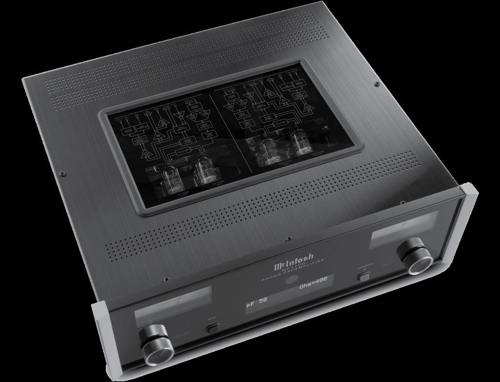

29 Photo 29
C22 Stereophonic Preamplifier Owner s Manual
 McIntosh Laboratory, Inc. 2 Chambers Street Binghamton, New York C22 Stereophonic Preamplifier Owner s Manual 13903-2699 Phone: 607-723-3512 www.mcintoshlabs.com 2 The lightning flash with arrowhead, within
Audio Control Center
 Audio Control Center C45 Owner s Manual McIntosh Laboratory, Inc. 2 Chambers Street Binghamton, New York 13903-2699 Phone: 607-723-3512 FAX: 607-724-0549 The lightning flash with arrowhead, within an equilateral
MAC7200 Receiver Owner s Manual
 McIntosh Laboratory, Inc. 2 Chambers Street Binghamton, New York MAC7200 Receiver Owner s Manual 13903-2699 Phone: 607-723-3512 www.mcintoshlabs.com Important Safety Information is supplied in a separate
508 Phono Preamplifier. Boulder Amplifiers, Inc. 255 S. Taylor Ave. Louisville, CO (303) /1/2018 Rev. 1.
 /1/2018 Rev. 1.") 508 Phono Preamplifier 6/1/2018 Rev. 1.0 P/N: 91053 Boulder Amplifiers, Inc. 255 S. Taylor Ave. Louisville, CO 80027 (303) 449-8220 www.boulderamp.com About About Boulder Amplifiers, Inc. Boulder was founded
508 Phono Preamplifier 6/1/2018 Rev. 1.0 P/N: 91053 Boulder Amplifiers, Inc. 255 S. Taylor Ave. Louisville, CO 80027 (303) 449-8220 www.boulderamp.com About About Boulder Amplifiers, Inc. Boulder was founded
CP1 OAD. Owner s Manual. Stereo Control Preamplifier. Ultrafidelity
 OAD Ultrafidelity CP1 Stereo Control Preamplifier Owner s Manual Contents Section Page No. Introduction........................................................................ 1 Warnings.................................................................................
Boulder 1010 Preamplifier
 Boulder 1010 Preamplifier Owners Manual 10/1/03 Boulder Amplifiers, Inc. 3235 Prairie Ave. Boulder, CO 80301 www.boulderamp.com APPENDIX RECORDING BOULDER LINK PROGRAMMING REMOTE CONTROL OPERATION GETTING
The performance of a lifetime. Owner s Manual MOON 110LP v2 Phono Preamplifier
 The performance of a lifetime Owner s Manual MOON 110LP v2 Phono Preamplifier MOON by Simaudio simaudio.com Simaudio Ltd 1345 Newton Road, Boucherville, Québec J4B 5H2 CANADA Date Code: 20180831 01 INTRODUCTION
COHERENCE ONE PREAMPLIFIER
 COHERENCE ONE PREAMPLIFIER OWNER S MANUAL TABLE OF CONTENTS Introduction Features Unpacking Instructions Installation Phono Cartridge Loading Basic Troubleshooting Technical Specifications Introduction
N o_ INTEGRATED AMPLIFIER
 N o_ 585.5 INTEGRATED AMPLIFIER 585.5 INTEGRATED AMPLIFIER WITH PURE PHONO STAGE Introducing the Mark Levinson 585.5 Integrated Amplifier. With unsurpassed analog performance, advanced digital audio capability
VPS 100 YPSILON PHONO STAGE. OWNERS MANUAL V1 01/01/2010 All rights reserved
 VPS 100 YPSILON PHONO STAGE OWNERS MANUAL V1 01/01/2010 All rights reserved INTRODUCTION Thank you for trusting YPSILON ELECTRONICS. We assure you that you have made an excellent purchase. Your phono stage
110LP MOON Series. Phono Preamplifier. Owner s Manual
 Phono Preamplifier Owner s Manual Owner s Manual I Table of Contents Introduction 4 Unpacking 5 Installation & Placement 5 Circuit Board Layout s 6 Internal Adjustments 7 Rear Panel Connections 8 Operating
CONSONANCE PREAMPLIFIER OWNER S MANUAL
 CONSONANCE PREAMPLIFIER OWNER S MANUAL TABLE OF CONTENTS Introduction Initial Inspection Features Installation Input Impedance Adjustments Preamplifier Internal View Impedance Adjustment Diagram Overall
ModWright Instruments, Inc. PH 150 Tube Phono Stage Owner s Manual
 ModWright Instruments, Inc. PH 150 Tube Phono Stage Owner s Manual Manufactured by ModWright Instruments, Inc. 21919 399th St., Amboy, WA 98601 USA www.modwright.com 1 CAUTIONS: Do not operate or power
MclNTOSH MODEL C-4 and C-4P
 INSTRUCTION MANUAL MclNTOSH MODEL C-4 and C-4P AUDIO COMPENSATORS McINTOSH LABORATORY, INC. 320 Water St. Binghamton, N. Y. U.S.A. - 1 - INSTRUCTION MANUAL McINTOSH MODEL C-4 and C-4P AUDIO COMPENSATORS
2012: Celebrating 40 Years of the World s Best Audio Systems
 forty years 2012: Celebrating 40 Years of the World s Best Audio Systems In 1972, Mark Levinson set out to prove to the world their high-fidelity components could provide a level of sonic performance that
Phono Amplifier brinkmann «EDISON» Manual.
 Phono Amplifier brinkmann «EDISON» ----------------------------------------------------------------------------------------------- Manual Preface We congratulate you on the purchase of our «EDISON» phono
Stereo Box Pre Box Amp Box Amp Box Mono Switch Box. Tuner Box Dock Box F / V Phono Box MM Record Box USB Phono Box II
 Overview Box Program Stereo Box Pre Box Amp Box Amp Box Mono Switch Box Tuner Box Dock Box F / V Phono Box MM Record Box USB Phono Box II Phono Box II USB Phono Box SE II Tube Box II Tube Box SE II Head
THE NOVA PHONOMENA MUSICAL SURROUNDINGS PRESENTS: PHONOGRAPH PREAMPLIFIER OWNER S MANUAL. Musical Surroundings. status
 MUSICAL SURROUNDINGS PRESENTS: THE NOVA PHONOMENA PHONOGRAPH PREAMPLIFIER Musical Surroundings Nova Phonomena Phono Preamplifier status OWNER S MANUAL TABLE OF CONTENTS 1.0) INTRODUCTION..3 2.0) INTERNAL
Low Noise Solid State Phono Preamplifier User's Guide and Operating Information
 Bel Canto Design PHONO 1 Low Noise Solid State Phono Preamplifier User's Guide and Operating Information Bel Canto Design 212 Third Avenue North Suite 345 Minneapolis, MN 55401 Phone: (612) 317.4550 Fax:
Owner's Manual. Model PH6 PHONO PREAMPLIFIER.
 Owner's Manual Model PH6 PHONO PREAMPLIFIER 3900 ANNAPOLIS LANE NORTH / PLYMOUTH, MINNESOTA 55447-5447 / PHONE: 763-577-9700 FAX: 763-577-0323 www.audioresearch.com Contents Model PH6 Page No. Preface.......................................................1
Table of Contents. Read This First.2. Introduction by Jim Fosgate...3. Unpacking..4. Tubes and Tube shield Installation 5. Product Placement...
 Owner s Manual Table of Contents Read This First.2 Introduction by Jim Fosgate...3 Unpacking..4 Tubes and Tube shield Installation 5 Product Placement...6 Connecting your Fosgate Signature..7 Phono stage
bel canto SEP2 Single Ended Triode Tube Preamplifier User's Guide and Operating Information
 bel canto SEP2 Single Ended Triode Tube Preamplifier User's Guide and Operating Information Bel Canto Design 212 Third Avenue North, Suite 274 Minneapolis, MN 55401 USA Phone: 612 317.4550 Fax: 612.359.9358
Boulder 1012 DAC Preamplifier
 Boulder 1012 DAC Preamplifier Owners Manual 10/27/03 Boulder Amplifiers, Inc. 3235 Prairie Ave. Boulder, CO 80301 www.boulderamp.com APPENDIX RECORDING BOULDER LINK PROGRAMMING REMOTE CONTROL OPERATION
Owner s Manual. Model REFERENCE PHONO 2 P R E A M P L I F I E R
 Owner s Manual Model REFERENCE PHONO 2 P R E A M P L I F I E R 3900 ANNAPOLIS LANE NORTH / PLYMOUTH, MINNESOTA 55447-5447 / PHONE: 763-577-9700 FAX: 763-577-0323 www.audioresearch.com Contents 1 Model
USER MANUAL GOLDMUND MIMESIS 32.5 Universal Acoustic Processor
 USER MANUAL GOLDMUND MIMESIS 32.5 Universal Acoustic Processor Congratulations. Thank you for purchasing the Goldmund MIMESIS 32.5 UNIVERSAL ACOUSTIC PROCESSOR. You have acquired the best multi-usage acoustic
Owner s Manual. Model PH8 Phono Preamplifier
 Owner s Manual Model PH8 Phono Preamplifier 2 Contents Model PH8 Phono Preamplifier Illustrations 4 Preface 5 Warnings 5 Packaging 5 Front Panel Controls 5 6 Remote Control Functions 6 Connections 6 Installation
USER MANUAL GOLDMUND PH3 Phono Preamplifier
 USER MANUAL GOLDMUND PH3 Phono Preamplifier Congratulations. Thank you for purchasing the Goldmund PH3 Phono Preamplifier. You have acquired the best Phono Preamplifier ever made for professional and domestic
Mapletree Audio Design
 Ultra 4C Preamplifier Mapletree Audio Design Ultra 4C Stereo Phono/Line Preamplifier PS 2D Power Supply User s Manual Rev. Mar. 22, 2019 Mapletree Audio Design R. R. 1, Seeley's Bay, Ontario, Canada, K0H
Design Brief - I35 and I35 DAC Stereo Integrated Amplifier
 Design Brief - I35 and I35 DAC Stereo Integrated Amplifier The I35 and I35 DAC are the latest iteration of Primare s now iconic 30 Series integrated amplifiers, and is the first to use the new UFPD 2 power
Sphinx II. Owner s Manual. Tube Hybrid Integrated Power Amplifier. Rogue Audio, Inc. 3 Marian Lane Brodheadsville, PA Issue date: 08/01/16
 Sphinx II Tube Hybrid Integrated Power Amplifier Owner s Manual Rogue Audio, Inc. 3 Marian Lane Brodheadsville, PA 18322 Issue date: 08/01/16 TABLE OF CONTENTS 1) Introduction 2 2) Unpacking the Sphinx
Owner s Manual. Reference Phono 2 SE Phono Preamplifier
 Owner s Manual Reference Phono 2 SE Phono Preamplifier 2 Contents Model Reference Phono 2 SE Phono Preamplifier Illustrations 4 Preface 5 Warnings 5 Packaging 5 Front Panel Controls 5 6 Remote Control
H I G H D E F I N I T I O N. Reference Phono 3
 H I G H D E F I N I T I O N Reference Phono 3 Thank you for choosing the Reference Phono 3 to be a part of your high performance music listening system. Since 1970, Audio Research has been creating some
Operating instructions. Modular preamplifier OVATION PA8
 Operating instructions Modular preamplifier OVATION PA8 Dear customer, thank you for purchasing this AVM product. you own now a versatile, excellent sounding hifi component. Before enjoying music, please
J R Sky, Inc. tel: fax:
 STEREO OPTICAL RECORDING SYSTEM N UOPTIX STEREO OPTICAL RECORDING MONITOR LEFT SYSTEM MODE PREVIEW RECORD BIAS RECORD REV SETUP TEST RIGHT INPUT SETUP INPUT BIAS SETUP BIAS INPUT STEREO AUX MONO DIRECT
ACUBRITE 23 SS. Manual. Stainless Steel Chassis 23" LCD Display. Content
 ACUBRITE 23 SS Stainless Steel Chassis 23" LCD Display Manual Introduction... 2 Hardware Installation... 2 The Display Timing... 5 The Display Outline Dimensions... 6 The Display Controls... 7 The Screen
MOMENTUM PHONOSTAGE OWNER S MANUAL
 MOMENTUM PHONOSTAGE OWNER S MANUAL A note from Dan D Agostino FOUNDER, CEO, AND CHIEF DESIGNER OF DAN D AGOSTINO MASTER AUDIO SYSTEMS Thank you for investing in my Momentum phonostage. For me, this component
The Majik System. Pack /07
 To learn more about any aspect of Linn products and the company behind them, visit www.linn.co.uk or contact us at one of the centres below: The Majik System Linn Products Limited Glasgow Road, Waterfoot,
MT2 Precision Turntable Owner s Manual
 McIntosh Laboratory, Inc. 2 Chambers Street Binghamton, New York MT2 Precision Turntable Owner s Manual 13903-2699 Phone: 607-723-3512 www.mcintoshlabs.com Important Safety Information is supplied in a
BP2-MM MM Phono Preamplifier Owner s Manual
 BP2-MM MM Phono Preamplifier Owner s Manual Important Safety Instructions The lightning flash with arrowhead symbol within an equilateral triangle, is intended to alert the user to the presence of un-insulated
SATRI AMPLIFIER AMP-51R. Owner s Manual
 SATRI AMPLIFIER AMP-51R Owner s Manual contents SAFETY INSTRUCTIONS 4 INTRODUCTION 6 OVERVIEW (FRONT PANEL) 8 OVERVIEW (REAR PANEL) 9 OVERVIEW (REMOTE CONTROL) 1 1 OPERATION 12 TROUBLESHOOTING 13 SPECIFICATION
Hegel HD20 High End D/A Converter
 Hegel HD20 High End D/A Converter www.hegel.com info@hegel.com USER GUIDE Congratulations on your new HEGEL! Every Hegel product is based on a simple philosophy: The audio reproduction instrument shall
ALLNIC AUDIO H 1500 II PLUS PHONO STAGE
 ALLNIC AUDIO H 1500 II PLUS PHONO STAGE OWNER S MANUAL ALLNIC AUDIO H-1500 II PLUS PHONO STAGE Thank you for purchasing this Allnic Audio H 1500 II PLUS Phono Stage. We are certain your trust in Allnic
Professional Fidelity Mastering Grade Listening
 Professional Fidelity Mastering Grade Listening Director ON SOURCE VOLUME VOLTAiR 120V DC Audio Rail DAC Preamplifier This User Manual is optimized for Acrobat Reader. Interactive buttons may not appear
VK-P10SE WARRANTY REGISTRATION FORM
 VK-P10SE WARRANTY REGISTRATION FORM Unit Serial Number: Customer Name: Address: Date of Purchase: Purchased From: Dealer Name: Address: IMPORTANT NOTE: In order to receive the full five-year product warranty,
ECP 2. Owner's Manual. High Performance Balanced Phono Stage. Version 1.0 ENGLISH
 ECP 2 High Performance Balanced Phono Stage Owner's Manual Version 1.0 EN ENGLISH Welcome to the world of Electrocompaniet! We thank you for choosing an Electrocompaniet high-end product. At Electrocompaniet
Rhea PHONO STAGE. Aesthetix Audio Corporation 5220 Gabbert Rd., Suite A Moorpark, CA Phone: (805)
") Rhea PHONO STAGE Aesthetix Audio Corporation 5220 Gabbert Rd., Suite A Moorpark, CA. 93021 Phone: (805) 529-9901 INTRODUCTION Thank you for purchasing the Rhea Phono Stage. The Rhea is a groundbreaking
Rhea PHONO STAGE Aesthetix Audio Corporation 5220 Gabbert Rd., Suite A Moorpark, CA. 93021 Phone: (805) 529-9901 INTRODUCTION Thank you for purchasing the Rhea Phono Stage. The Rhea is a groundbreaking
RoHS. Atma-Sphere Music Preamplifier. model P-2 OWNER'S MANUAL. Please study this document carefully before using equipment
 1742 Selby Av. St. Paul, MN 55104 651 690 2246 atma sphere.com Atma-Sphere Music Preamplifier model P-2 OWNER'S MANUAL Please study this document carefully before using equipment RoHS CONGRATULATIONS!
USER MANUAL Goldmund PH3.8 Phono Preamplifier
 USER MANUAL Goldmund PH3.8 Phono Preamplifier Congratulations. Thank you for purchasing the Goldmund PH3.8 Phono Preamplifier. You have acquired the best Phono Preamplifier ever made for professional and
BP2-MM/MC Phono Preamplifier Owner s Manual
 BP2-MM/MC Phono Preamplifier Owner s Manual Important Safety Instructions The lightning flash with arrowhead symbol within an equilateral triangle, is intended to alert the user to the presence of un-insulated
THE MclNTOSH C 504 STEREO PREAMPLIFIER
 THE MclNTOSH C 504 STEREO PREAMPLIFIER Reading Time: 30 Minutes Price: $2.00 VARIOUS REGULATORY AGENCIES REQUIRE THAT WE BRING THE FOLLOWING INFORMATION TO YOUR ATTENTION. PLEASE READ IT CAREFULLY. WARNING:
Pre1. Balanced Control Preamplifier. User's Guide and Operating Information
 Pre1 Balanced Control Preamplifier User's Guide and Operating Information Bel Canto Design 212 Third Avenue North Suite 345 Minneapolis, MN 55401 Phone: (612) 317.4550 Fax: (612) 359.9358 Email: Info@BelCantoDesign.com
Element 78 MPE-200. by Summit Audio. Guide To Operations. for software version 1.23
 Element 78 MPE-200 by Summit Audio Guide To Operations for software version 1.23 TABLE OF CONTENTS IMPORTANT SAFETY AND GROUNDING INSTRUCTIONS COVER 1. UNPACKING AND CONNECTING...3 AUDIO CONNECTIONS...4
S0 Radio Broadcasting Mixer. June catalogue. Manufacturers of audio & video products for radio & TV broadcasters
 S0 Radio Broadcasting Mixer June 2012 catalogue Manufacturers of audio & video products for radio & TV broadcasters S0 Radio Broadcasting Mixer A simple radio mixer for novice and professional users The
WARNING To reduce risk of fire or electric shock, do not expose this preamplifier to moisture, rain, or excessive humidity.
 CAUTION To reduce risk of electric shock, do not remove any of the phono preamplifier s cover plates or screws. There are no user serviceable parts inside. Contact qualified service personnel. WARNING
Boulder 2020 Advance D/A Converter
 Boulder 2020 Advance D/A Converter Owners Manual V1.2 8/1/98 TABLE OF CONTENTS GETTING STARTED Placement of your 2020 D/A Converter........................................1-1 Connecting the Power Supply
M R X
 MRX 710 / 510 / 310 AWARD-WINNING A/V RECEIVERS ANTHEM ROOM CORRECTION SYSTEM A fantastic-sounding product well worthy of a serious audition don t delay. ~ What Hi Fi on the MRX 700 MRX 710 shown Among
music hall pa2.2 INSTRUCTION MANUAL music hall
 music hall pa2.2 INSTRUCTION MANUAL music hall http://www.musichallaudio.com CONGRATULATIONS ON YOUR PURCHASE You have selected an exceptional phono preamplifier. Each component used in the construction
User Guide. REFERENCE PHONO 10 Phono Preamplifier D E F I N I T I O N
 User Guide REFERENCE PHONO 10 Phono Preamplifier H I G H D E F I N I T I O N 2 Contents Preface 3 Illustrations Audio Chassis 4 Power Supply Chassis 5 Warnings 6 Installation Installation of Vacuum Tubes
Hi-fi for music lovers...
 REGA RESEARCH LIMITED QUALITY HI-FI DESIGNED AND BUILT IN ENGLAND SINCE 1973. Hi-fi for music lovers... Rega Research Ltd first started making specialist Hi-Fi equipment in 1973. Back then life and the
Calaf integrated stereo amplifier
 Calaf integrated stereo amplifier USER GUIDE Congratulations on your new CONSONANCE! Our products are based on a simple philosophy: The component shall reproduce the original musical sound, purely and
WARNING To reduce risk of fire or electric shock, do not expose this preamplifier to moisture, rain, or excessive humidity.
 CAUTION To reduce risk of electric shock, do not remove any of the phono preamplifier s cover plates or screws. There are no user serviceable parts inside. Contact qualified service personnel. WARNING
OWNERS MANUAL LUNATEC V3 MICROPHONE PREAMPLIFIER AND A/D CONVERTER
 OWNERS MANUAL LUNATEC V3 MICROPHONE PREAMPLIFIER AND A/D CONVERTER LUNATEC 35 +48 35 +48 30 40 30 40 0 25 45 25 45 3 192 1 1 6 176.4 20 50 20 50 9 96 12 PEAK 88.2 55 55 RESET 48 10 60 2 10 60 2 21 44.1
operating instructions integrated amplifiers EVOLUTION A3.2, A5.2 / T preamplifiers EVOLUTION PA3.2, PA5.2
 operating instructions integrated amplifiers EVOLUTION A3.2, A5.2 / T preamplifiers EVOLUTION PA3.2, PA5.2 Dear customer, thank you for purchasing this AVM product. you own now a versatile, excellent sounding
clipping; yellow LED lights when limiting action occurs. Input Section Features
 ELX-1A Rack-Mount Mic/Line Mixer Four inputs, one output in a single rack space Very-highery-high-quality audio performance High reliability Extensive filtering circuitry and shielding protect against
Model 22.1 HDCD D/A Converter Instructions
 Model 22.1 HDCD D/A Converter Instructions The VAC 22.1 is one of the first D/A converters ever designed from the ground up around the Pacific Microsonics PMD-100 HDCD digital filter. This is one of the
Reference 150 LINEAR
 Reference 150 LINEAR USER GUIDE Congratulations on your new CONSONANCE! Our products are based on a simple philosophy: The component shall reproduce the original musical sound, purely and naturally. The
Model CMX3838A2 AV Matrix Switch with DSP audio (firmware 1.0)
") Model CMX3838A2 AV Matrix Switch with DSP audio (firmware 1.0) Overview: This product is a full featured video & audio matrix switch. It is most commonly used to independently distribute video & audio
Model CMX3838A2 AV Matrix Switch with DSP audio (firmware 1.0) Overview: This product is a full featured video & audio matrix switch. It is most commonly used to independently distribute video & audio
INSTRUCTIONS FOR USE Pro-Ject Phono Box DS2 USB
 INSTRUCTIONS FOR USE Pro-Ject Phono Box DS2 USB Dear music lover, thank you for purchasing a Pro-Ject Audio phono amplifier. In order to achieve maximum performance and reliability you should study these
PRO-ScalerV2HD VGA to HDMI & Audio Scaler Converter. User s Guide. Made in Taiwan
 VGA to HDMI & Audio Scaler Converter User s Guide Made in Taiwan Congratulations for owning a gofanco product. Our products aim to meet all your connectivity needs wherever you go. Have fun with our products!
The VAC Phi Alpha Triode Preamplifier. Operation & Maintenance Information
 F The VAC Phi Alpha Triode Preamplifier Operation & Maintenance Information Valve Amplification Company Manual issued 02/15/2008 CAUTION THE PREAMPLIFIER AND POWER SUPPLY CONTAIN POTENTIALLY LETHAL VOLTAGES,
Owner s guide How to use your new Opalum Furniture Sound System
 Owner s guide How to use your new Opalum Furniture Sound System Table of contents 1. The Opalum Furniture Sound System 3 2. Controls and connectors 4 3. The status indicator 5 3.1 Modes of the status indicator
CD360 INSTRUCTION MANUAL
 CD360 INSTRUCTION MANUAL Audioart Herenweg 15 3602 AM Maarssen The Netherlands Telephone: + 31 346 59 02 90 Website: www.vanmedevoort.com Email: info@audioart.nl 2013-12 vm INSTRUCTION MANUAL Thank you
SONy BID SPECIFICATION FOR POWERED MIXER MODEL NUMBER SRP-X500P
 SONy BID SPECIFICATION FOR POWERED MIXER MODEL NUMBER SRP-X500P INSTRUCTIONS: REMOVE THIS COVER PAGE AND ADD TO REQUESTS FOR QUOTATION AND PROPOSALS. THE OBJECTIVE OF THIS BID SPECIFICATION IS TO ASSIST
A y r e. K-1x Preamplifier. Owner s Manual
 A y r e K-1x Preamplifier Owner s Manual Table of Contents Welcome to Ayre........................... 2 Installation and Operation......................... 3 Optimizing the Phono Stage........................
Phono 2-SB Owner s Manual
 Phono 2-SB Owner s Manual Table of Contents Owner s Manual for the LKV Phono 2-S... 2 1. Installation... 2 2. Unit Configuration... 3 2-A. Overview... 3 Figure 2 Circuit board for one channel.... 4 Figure
LAMM INDUSTRIES, INC.
 LAMM INDUSTRIES, INC. TheLP1Si gnat ur e phono preamplifier LAMM INDUSTRIES, INC. LP1 Signature dual monaural phono preamplifier The dual monaural phono preamplifier model LP1 Signature is the ultimate
OPERATION NOTES FOR PSIDEX AUDIO PGP-1A PRE-AMPLIFIER DESCRIPTION INSTALLATION
 OPERATION NOTES FOR PSIDEX AUDIO PGP-1A PRE-AMPLIFIER DESCRIPTION The Psidex Audio Laboratory PGP- 1A is a vacuum tube based microphone preamp and program line amplifier designed to provide solid, robust
Channel D Lino. Balanced Direct-Coupled Wide Bandwidth Low Distortion Low Noise Precision Phono Preamplifier. Installation and Use Guide
 Channel D Lino Balanced Direct-Coupled Wide Bandwidth Low Distortion Low Noise Precision Phono Preamplifier Installation and Use Guide For Low Output / Low Impedance Moving-Coil Phono Cartridges Use Guide
Winmate Communication INC.
 20.1 Military Grade Display Model: R20L100-RKA2ML User s Manual Winmate Communication INC. May, 2011 1 IMPORTANT SAFETY INSTRUCTIONS Please read these instructions carefully before using the product and
Owner s Manual PRE1. v1.2. Triode Class A Line Preamplifier
 Owner s Manual PRE1 Triode Class A Line Preamplifier www.lab12.gr v1.2 Table of Contents It is yours Features Installation & Placement Front Panel Rear Panel Remote Control Main connections For the safety
OWNER MANUAL PV9 VACUUM TUBE PREAMPLIFIER. conrad-johnson design
 OWNER MANUAL PV9 VACUUM TUBE PREAMPLIFIER conrad-johnson design 703-698-8581 Congratulations on your purchase of the conrad-johnson model PV9 vacuum tube preamplifier. In it, you have acquired one of the
MULTI CHANNEL AV RECEIVERSTR-DH750/STR- DH550
 MULTI CHANNEL AV RECEIVERSTR-DH750/STR- DH550 PROTECTOR The receiver will automatically turn off after a few seconds. Check the followings: There may be an electrical surge or power failure. Unplug the
Recording to Tape (Analogue or Digital)...10
...10") c o n t e n t s DUAL MIC-PRE Green Dual Mic Pre (introduction).............................4 Section (i): Setting Up Power Connections...........................................4 Power Supply................................................5
c o n t e n t s DUAL MIC-PRE Green Dual Mic Pre (introduction).............................4 Section (i): Setting Up Power Connections...........................................4 Power Supply................................................5
Introduction Front Panel Functions Rear Panel Functions Precautions Placement & Ventilation... 5
 Contents Introduction... 2 Front Panel Functions... 3 Rear Panel Functions... 3 Precautions... 5 Placement & Ventilation... 5 Installation & Operation... 5 Care & Maintenance... 7 Troubleshooting... 8
KORU. Phono Preamplifier Instruction Manual. The heart of music
 KORU Phono Preamplifier Instruction Manual The heart of music www.pliniusaudio.com Contents Introduction...2 Design Philosophy...3 Unpacking...4 Placement & Ventilation...4 Care & Maintenance...5 Precautions...6
PROFESSIONAL 2 CHANNEL SOLID-STATE MIC / LINE PREAMPLIFIER USER S MANUAL
 PROFESSIONAL 2 CHANNEL SOLID-STATE MIC / LINE PREAMPLIFIER USER S MANUAL SAFETY INSTRUCTIONS This symbol, wherever it appears, alerts you to important operating and maintenance instructions in the accompanying
HD-1603 Single Input MPEG-4 DVB-T HD Encoder/Modulator User Guide and Install Manual
 ZyCastR digi-mod HD Range digi-mod HD-1603 www.digi-modbyzycast.com HD-1603 Single Input MPEG-4 DVB-T HD Encoder/Modulator User Guide and Install Manual Table of Contents www.digi-modbyzycast.com Safety
RMX-44 & RMX-62 MIXING MATRIX. Installation & Operation Manual
 RMX-44 & RMX-6 MIXING MATRIX Installation & Operation Manual TABLE OF CONTENTS RMX-44 & RMX-6 INTRODUCTION... RMX-44 CALLOUTS... RMX-44 BLOCK DIAGRAM... RMX-6 CALLOUTS... 4 RMX-6 BLOCK DIAGRAM... 5 RMX-44
Connecting a Turntable to Your Computer
 http://www.virtual-vinyl.com Connecting a Turntable to Your Computer If you're new to vinyl playback, you may not know that the output of a standard turntable must be amplified and the signal properly
Solid State Logic S O U N D V I S I O N
 Solid State Logic S O U N D V I S I O N SUPERANALOGUE X - R A C K Super-Analogue Outboard XR622 X-Rack Master Module User s Guide This documentation package contains the User s Guide for your new X-Rack
OWNER S MANUAL MODEL ZP3 REV. DATE 2/2016. Zen Triode Phono Stage Model ZP3.
 Zen Triode Phono Stage Model ZP3 INTRODUCTION The Zen Triode Phono Stage is an all tube, single-ended design built using the popular 12AX7 dual triodes for amplification and equalization and a 12AU7 dual
PREAMPLIFIER INTRODUCTION INSTRUCTIONS FOR USE. Thank you for purchasing the Musical Fidelity A3 CR remote control preamplifier.
 INTRODUCTION A3 CR PREAMPLIFIER INSTRUCTIONS FOR USE Thank you for purchasing the Musical Fidelity A3 CR remote control preamplifier. Used properly and carefully, it should give you many years of outstanding
USB Phono Plus. Project Series USER S MANUAL. Audiophile Computer Interface
 USB Phono Plus Audiophile Computer Interface Project Series USER S MANUAL IMPORTANT SAFETY INSTRUCTION READ FIRST This symbol, whenever it appears, alerts you to the presence of uninsulated dangerous voltage
Hegel HD10 High End D/A Converter
 Hegel HD10 High End D/A Converter www.hegel.com info@hegel.com USER GUIDE Congratulations on your new HEGEL! Every Hegel product is based on a simple philosophy: The audio reproduction instrument shall
20/20 -a phono preamplification instrument by Sutherland Engineering
 20/20 -a phono preamplification instrument by Sutherland Engineering OWNER S MANUAL A note from designer RON SUTHERLAND: I like design challenges. That is how all new products begin. This time the challenge
7000 Series RossGear Series RossGear
 7000 Series RossGear 7000 Series RossGear AUDIO AND VIDEO FRAMES & ACCESSORIES VFR-7214 1RU Analog Video Products Mounting Frame page 6 VFR-7210 2RU Analog Video Products Mounting Frame page 6 VFR-7514
Table of Contents FCC COMPLIANCE STATEMENT... 4 WARNINGS AND PRECAUTIONS... 4 WARRANTY... 5 STANDARD WARRANTY... 5 TWO YEAR WARRANTY... 5 DISPOSAL...
 1 Table of Contents FCC COMPLIANCE STATEMENT... 4 WARNINGS AND PRECAUTIONS... 4 WARRANTY... 5 STANDARD WARRANTY... 5 TWO YEAR WARRANTY... 5 DISPOSAL... 6 1. INTRODUCTION... 7 FEATURES... 7 2. CONNECTIONS
Operating Manual. Mark Levinson Nº25 Dual Monaural Phono Preamplifier. Madrigal Audio Laboratories, Inc. 1
 Operating Manual Mark Levinson Nº25 Dual Monaural Phono Preamplifier Madrigal Audio Laboratories, Inc. 1 WARNING: TO REDUCE THE RISK OF FIRE OR ELECTRIC SHOCK, DO NOT EXPOSE THIS APPLIANCE TO RAIN OR MOISTURE.
OWNER S MANUAL TOP LINE PREAMP 088
 OWNER S MANUAL TOP LINE PREAMP 088 HIGH END MADE IN GERMANY BURMESTER AUDIOSYSTEME GMBH KOLONNENSTR. 30G 10829 BERLIN GERMANY TEL +49/(0)30/78 79 68 0 FAX +49/(0)30/78 79 68 68 E-MAIL: mail@burmester.de
AES-404 Digital Audio Switcher/DA/Digital to Analog Converter
 Broadcast Devices, Inc. AES-404 Digital Audio Switcher/DA/Digital to Analog Converter Technical Reference Manual Broadcast Devices, Inc. Tel. (914) 737-5032 Fax. (914) 736-6916 World Wide Web: www.broadcast-devices.com