R&S SGS100A SGMA RF Source Specifications
|
|
|
- Gregory Gibbs
- 5 years ago
- Views:
Transcription


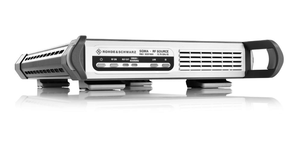
1 R&S SGS100A SGMA RF Source Specifications Test & Measurement Data Sheet 04.00
2 CONTENTS Key features... 3 Definitions... 4 RF performance... 5 Frequency... 5 Reference frequency... 5 Level... 6 Spectral purity... 7 Phase coherence (R&S SGS-K90 option)... 8 Pulse modulation (R&S SGS-K22 option)... 9 Input for external pulse modulation and pulse generator trigger... 9 Internal pulse generator... 9 I/Q modulation I/Q modulator Baseband bypass mode I/Q inputs Remote control Connectors Rear panel connectors General data Ordering information Rohde & Schwarz R&S SGS100A SGMA RF Source
3 Key features Dedicated ATE signal generation I/Q-modulated or pure CW source in frequency range from 80 MHz to GHz (I/Q) and 1 MHz to GHz (CW) Very fast settling times via PCIe and Ethernet interface Maximum level of typ. > +20 dbm (with electronic attenuator) Optional wear-free electronic attenuator External software (SGMA GUI) for remote control of multiple instruments Field-upgradeable Space-saving operation due to small dimensions Smallest signal generator in its class: 1 height unit, ½ 19" Lightweight High performance at an attractive price Low SSB phase noise of 133 dbc (meas., 20 khz carrier offset, f = 1 GHz, 1 Hz measurement bandwidth) Wideband noise of < 145 dbc Nonharmonics of < 76 dbc (> 10 khz carrier offset, f 1500 MHz) Very high level accuracy and repeatability Optional pulse modulation capability and internal pulse generator Optional high-stability reference oscillator Optional coherent LO input/output Minimized total cost of ownership Attractive initial cost Long calibration interval Simplified error diagnostics through built-in selftests Rohde & Schwarz R&S SGS100A SGMA RF Source 3

4 Definitions General Product data applies under the following conditions: Three hours storage at ambient temperature followed by 30 minutes warm-up operation Specified environmental conditions met Recommended calibration interval adhered to All internal automatic adjustments performed, if applicable Specifications with limits Represent warranted product performance by means of a range of values for the specified parameter. These specifications are marked with limiting symbols such as <,, >,, ±, or descriptions such as maximum, limit of, minimum. Compliance is ensured by testing or is derived from the design. Test limits are narrowed by guard bands to take into account measurement uncertainties, drift and aging, if applicable. Specifications without limits Represent warranted product performance for the specified parameter. These specifications are not specially marked and represent values with no or negligible deviations from the given value (e.g. dimensions or resolution of a setting parameter). Compliance is ensured by design. Typical data (typ.) Characterizes product performance by means of representative information for the given parameter. When marked with <, > or as a range, it represents the performance met by approximately 80 % of the instruments at production time. Otherwise, it represents the mean value. Nominal values (nom.) Characterize product performance by means of a representative value for the given parameter (e.g. nominal impedance). In contrast to typical data, a statistical evaluation does not take place and the parameter is not tested during production. Measured values (meas.) Characterize expected product performance by means of measurement results gained from individual samples. Uncertainties Represent limits of measurement uncertainty for a given measurand. Uncertainty is defined with a coverage factor of 2 and has been calculated in line with the rules of the Guide to the Expression of Uncertainty in Measurement (GUM), taking into account environmental conditions, aging, wear and tear. Typical data as well as nominal and measured values are not warranted by Rohde & Schwarz. 4 Rohde & Schwarz R&S SGS100A SGMA RF Source
5 RF performance Frequency Frequency range with the R&S SGS-B106 option 1 MHz to 6 GHz with the R&S SGS-B106 and 1 MHz to GHz R&S SGS-B112 options with the R&S SGS-B106V option 1 MHz to 6 GHz (CW), 80 MHz to 6 GHz (I/Q) with the R&S SGS-B106V and R&S SGS-B112V options 1 MHz to GHz (CW), 80 MHz to GHz (I/Q) Resolution of setting Hz Resolution of synthesis f = 1 GHz µhz (nom.) Setting time to within < for f > 500 MHz or < 100 Hz for f 500 MHz with PCIe or Ethernet (fast socket) remote < 500 μs control Resolution of phase offset setting 0.1 Reference frequency Frequency error at time of calibration in production < with the R&S SGS-B1 option < Aging < /year (after 30 days of uninterrupted operation) with the R&S SGS-B1 option < /day, < /year Temperature effect (0 C to +50 C) < with the R&S SGS-B1 option < Warm-up time to nominal thermostat temperature 10 min (with R&S SGS-B1 option only) Reference frequency output Connector type REF/LO OUT on rear panel SMA female Output frequency sine wave instrument set to internal reference 10 MHz, 1000 MHz instrument set to external reference applied external reference input frequency or 1000 MHz Output level +6 dbm to +12 dbm, 9 dbm (typ.) Source impedance 50 Ω (nom.) Reference frequency input Connector type REF/LO IN on rear panel SMA female Input frequency 10 MHz, 13 MHz, 100 MHz, 1000 MHz Frequency locking range ± Input level range 0 dbm to +16 dbm Input impedance 50 Ω (nom.) Rohde & Schwarz R&S SGS100A SGMA RF Source 5
6 Level Setting Characteristic: auto The step attenuator is switched over automatically. The output level is specified over the full range from 120 dbm to +15 dbm. Setting Characteristic: uninterrupted level setting The level is set without changing the step attenuator. The step attenuator is fixed to the current setting. Level changes are performed without interruption. The maximum interruption-free setting range is limited. If this range is exceeded, the spectral purity of the output signal may decrease. Setting range 20 dbm to +25 dbm with the R&S SGS-B26 option 120 dbm to +25 dbm Specified level range 10 dbm to +15 dbm (PEP) 1 with the R&S SGS-B26 option 120 dbm to +15 dbm (PEP) 1 Resolution of setting 0.01 db Level error Setting Characteristic: auto, temperature range from +18 C to +33 C 1 MHz f 3 GHz < 0.5 db 3 GHz < f GHz < 0.9 db Additional level error for pulse modulation pulse width 100 ns < 0.3 db (meas.) Output impedance VSWR in 50 Ω system in full frequency range, < 2.0 Setting Characteristic: auto in full frequency range, with the < 1.8 R&S SGS-B26 option Setting time to < 0.1 db deviation from final value, < 500 μs Setting Characteristic: auto, with PCIe or Ethernet (fast socket) remote control Interruption-free level setting range Setting Characteristic: uninterrupted level 0 db to +20 db setting Reverse power from 50 Ω maximum permissible RF power in output 0.5 W Maximum permissible DC voltage at RF power connector 35 V Histogram of level setting times measured via PCIe/Ethernet interface, Setting Characteristic auto. 1 PEP = peak envelope power. 6 Rohde & Schwarz R&S SGS100A SGMA RF Source
7 Spectral purity Maximum available level in CW mode, Setting Characteristic: auto, with the R&S SGS-B26 electronic step attenuator option (meas.). Harmonics level 8 dbm, CW, I/Q wideband off < 30 dbc Nonharmonics level > 10 dbm 2, offset > 10 khz from carrier f 1500 MHz < 76 dbc 1500 MHz < f 3000 MHz < 70 dbc 3000 MHz < f 6000 MHz < 64 dbc 6000 MHz < f MHz < 58 dbc Subharmonics level > 10 dbm 2 Wideband noise SSB phase noise f 3000 MHz < 76 dbc 3000 MHz < f 6500 MHz < 68 dbc 6500 MHz f MHz < 60 dbc 1 MHz f 6 GHz and < 145 dbc carrier offset 10 MHz, 6 GHz < f GHz and carrier offset 30 MHz, level > 5 dbm, Setting Characteristic: auto, 1 Hz measurement bandwidth, CW 200 MHz f 6 GHz and < 135 dbc carrier offset 10 MHz, 6 GHz < f GHz and carrier offset 30 MHz, level > 5 dbm, Setting Characteristic: auto, 1 Hz measurement bandwidth, I/Q 20 khz carrier offset, 1 Hz measurement bandwidth f = 1 GHz < 126 dbc, 133 dbc (meas.) f = 2 GHz < 120 dbc, 127 dbc (meas.) f = 10 GHz < 106 dbc, 113 dbc (meas.) 2 > 0 dbm for instruments without the R&S SGS-B26 electronic step attenuator. Rohde & Schwarz R&S SGS100A SGMA RF Source 7
8 SSB phase noise / dbc (1 Hz) Version 04.00, August GHz 6 GHz 3 GHz 1 GHz 100 MHz 10 MHz Frequency offset / Hz Phase coherence (R&S SGS-K90 option) SSB phase noise with the R&S SGS-B1 internal OCXO option (meas.). The R&S SGS-K90 option provides phase-coherent RF outputs for two or more instruments. For frequencies above 6.5 GHz (instruments equipped with the R&S SGS-B112 or R&S SGS-B112V frequency extension), the LO output and input frequency are set to half the output frequency. LO coupling modes REF/LO OUT states Phase drift over temperature this mode corresponds to internal LO operation; the REF/LO OUT connector can provide the internal LO oscillator signal to enable phase-coherent coupling on other instruments this mode corresponds to external LO operation at the REF/LO IN connector; the REF/LO OUT connector can provide the external LO oscillator signal to enable phase-coherent coupling on additional instruments. active local oscillator signal can be routed to the REF/LO OUT connector (in order to couple two or more instruments) drift of RF signal phase difference between two LO coupled instruments R&S SGS100A when changing ambient temperature by +1 C, f = 6 GHz, level = +10 dbm internal external REF/LO/OFF 0.4 (meas.) 8 Rohde & Schwarz R&S SGS100A SGMA RF Source
9 Input of phase coherence signal Connector type REF/LO IN on rear panel SMA female Input impedance 50 Ω (nom.) Input level range of external local oscillator 7 dbm to 13 dbm signal Frequency range of external local for RF setting 80 MHz to 6.5 GHz 80 MHz to 6.5 GHz oscillator signal for RF setting > 6.5 GHz to GHz 3.25 GHz to GHz Output of phase coherence signal Connector type REF/LO OUT on rear panel SMA female Output impedance 50 Ω (nom.) Output level range of internal local 7 dbm to 13 dbm oscillator signal Frequency range of internal local oscillator for RF setting 80 MHz to 6.5 GHz 80 MHz to 6.5 GHz signal for RF setting > 6.5 GHz to GHz 3.25 GHz to GHz Pulse modulation (R&S SGS-K22 option) The R&S SGS-K22 option provides pulse modulation capabilities. The pulse modulator can be controlled by an internal pulse generator (delivered with the R&S SGS-K22) or by an external pulse signal. Modulation source external, internal On/off ratio > 80 db Rise/fall time 10 % to 90 % of RF amplitude < 20 ns External pulse modulation delay 45 ns (meas.) Pulse repetition frequency 0 Hz to 10 MHz Video feedthrough level < 10 dbm, < 10 % of RF with the R&S SGS-B26 option Pulse overshoot f 500 MHz < 10 % Input for external pulse modulation and pulse generator trigger Connector type TRIG on rear panel SMA female Input impedance selectable 10 kω or 50 Ω (nom.) Threshold voltage 1 V (nom.) Input damage voltage ±5 V Input polarity selectable normal, inverse Internal pulse generator Pulse mode single pulse, double pulse Trigger mode free run, internally triggered auto externally triggered externally gated Active trigger edge positive or negative Pulse period Setting range 100 ns to 100 s Setting resolution 10 ns Pulse width Setting range the pulse widths of double pulses can be 20 ns to 100 s set independently Setting resolution 10 ns Pulse delay Setting range with external trigger 0 s to 100 s Setting resolution with external trigger 10 ns Double pulse delay Setting range 40 ns to 100 s Setting resolution 10 ns External trigger delay jitter < 20 ns Pulse/video output available on TRIG connector on rear panel in auto trigger mode LVTTL signal, 3.3 V (nom.) Rohde & Schwarz R&S SGS100A SGMA RF Source 9
10 I/Q modulation I/Q modulator Modulation bandwidth 80 MHz < f 1 GHz ±5 % of carrier frequency 1 GHz < f 12.7 GHz ±50 MHz 100 MHz < f 2.5 GHz, I/Q wideband ±20 % of carrier frequency 2.5 GHz < f GHz, I/Q wideband ±500 MHz RF frequency response 80 MHz < f 1 GHz, < 3 db (meas.) up to ±5 % of carrier frequency 1 GHz < f 12.7 GHz, up to ±50 MHz < 3 db (meas.) 100 MHz < f 2.5 GHz, < 6 db (meas.) up to ±20 % of carrier frequency, I/Q wideband 2.5 GHz < f GHz, < 9 db (meas.) up to ±500 MHz, I/Q wideband Carrier leakage without input signal, referenced to < 45 dbc, < 55 dbc (meas.) full-scale input 3 Suppression of image sideband up to ±10 MHz 40 db (meas.) Error vector measured with 16QAM, filter root cosine α = 0.5, 10 khz symbol rate f > 80 MHz, RMS < (0.4 % % f/ghz) f > 80 MHz, peak value < (0.8 % % f/ghz) 3GPP FDD digital standard, adjacent-channel leakage ratio (ACLR) test model 1, 64 DPCHs, level 10 dbm 4 PEP, frequency range from 1800 MHz to 2200 MHz 5 MHz offset > 67 db, 70 db (meas.) 10 MHz offset > 69 db, 71 db (meas.) I/Q impairment settings Offset setting range 5 % to +5 % Offset setting resolution 0.01 % Gain imbalance setting range 1.0 db to +1.0 db Gain imbalance setting resolution db Quadrature offset setting range 8 to +8 Quadrature offset setting resolution 0.01 Baseband bypass mode The baseband bypass mode allows generation of modulated signals below the I/Q modulator s specified frequency range. Externally generated signals applied to the I or Q baseband input connector can be leveled and amplified by the instrument and are provided at the RF output connector. For the baseband bypass mode, only the data specified in this section is valid. Level setting range 10 dbm to +25 dbm with the R&S SGS-B26 option 120 dbm to +25 dbm Specified level range 5 dbm to +15 dbm with the R&S SGS-B26 option 120 dbm to +15 dbm Frequency response 1 MHz f 80 MHz, level = 10 dbm < 3 db, < 1 db (meas.) Level error auto attenuator mode, temperature range < 3 db from +18 C to +33 C, referenced to fullscale input at I or Q connector, 1 MHz f 80 MHz Level linearity fixed attenuator mode, for setting range of 0 db to +20 db < 2 db, < 0.5 db (meas.) 3 Value applies after internal readjustment. 4 5 dbm for instruments without the R&S SGS-B26 electronic step attenuator. 10 Rohde & Schwarz R&S SGS100A SGMA RF Source
11 I/Q inputs Connector types I, Q on rear panel SMA female Input impedance 50 Ω (nom.) VSWR up to 100 MHz < MHz to 500 MHz < 1.5 Input voltage for full-scale input 2 2 Vi + Vq = 0.5 V Input damage voltage ±1 V (nom.) Remote control Systems PCIe (single lane) Ethernet (TCP/IP) 10/100/1000BaseT USB 2.0 Command set remote control via Ethernet, USB SCPI or compatible command sets remote control via PCIe Rohde & Schwarz instrument driver Connectors Rear panel connectors RF 50 Ω RF output SMA female REF/LO IN reference frequency input or SMA female external LO signal input REF/LO OUT reference frequency output or SMA female internal LO signal output I, Q input connector for I and Q baseband SMA female signals, input for I/Q vector-modulated IF signals up to 80 MHz TRIG trigger input/output, pulse input/output SMA female USB IN remote control of instrument USB (micro USB) LAN remote control of instrument RJ-45 PCI Express remote control of instrument single lane, according to PCI Express external cabling specification Rohde & Schwarz R&S SGS100A SGMA RF Source 11
12 General data Power supply AC input voltage range 100 V to 240 V ± 10 % AC supply frequency 50 Hz to 60 Hz, 5 %/+5 % Max. input current 1.7 A Power consumption 70 W (meas.) Power factor correction in line with EN Electrical safety Compliance in line with IEC , EN , CAN/CSA-C22.2 No , UL Test mark VDE-GS, CCSA US EMC Electromagnetic compatibility in line with EN class B, EN (industrial environment), EN Mechanical resistance Vibration sinusoidal 5 Hz to 150 Hz, max. 2 g at 55 Hz, const. 0.5 g at 55 Hz to 150 Hz, in line with EN random 10 Hz to 300 Hz, acceleration 1.2 g (RMS), in line with EN Shock in line with MIL-STD-810E, method no , procedure I, 40 g shock spectrum Environmental conditions Temperature range operating temperature range 0 C to +50 C, in line with EN , EN storage temperature range 40 C to +71 C Climatic resistance +40 C/95 % rel. humidity, in line with EN Altitude operating up to 4600 m storage up to 4600 m Dimensions W H D 250 mm 52.5 mm 401 mm (9.84 in 2.07 in in) 1 HU, ½ 19" rack width Weight when fully equipped 4.0 kg (8.82 lb) Calibration interval Recommended calibration interval 40 h/week operation in the full range of the specified environmental conditions 3 years 12 Rohde & Schwarz R&S SGS100A SGMA RF Source
13 Ordering information Designation Type Order No. SGMA RF Source 5 R&S SGS100A Including power cable, quick start guide and CD-ROM (with operating and service manual) Options 1 MHz to 6 GHz, CW (no modulation) R&S SGS-B MHz to 6 GHz, I/Q (with vector modulation) R&S SGS-B106V Frequency Extension to GHz, CW 6 R&S SGS-B Frequency Extension to GHz, I/Q 7 R&S SGS-B112V Electronic Step Attenuator R&S SGS-B Reference Oscillator OCXO R&S SGS-B Pulse Modulation R&S SGS-K Phase Coherent Input/Output R&S SGS-K Recommended extras 19" Rack Adapter R&S ZZA-KN (for two 1 HU instruments next to each other), suitable for installation of two R&S SGMA instruments 19" Rack Adapter R&S ZZA-KN (for one instrument and spacing module) Cable Kit R&S SGU100A to R&S SGS100A (side-by-side) R&S SGU-Z Connection Kit R&S SGU100A to R&S SGS100A R&S SGU-Z R&S SGMA Adapter R&S SGS-Z Accessories Documentation of Calibration Values R&S DCV Service options Extended Warranty, one year R&S WE1SGS100A Please contact your local Extended Warranty, two years R&S WE2SGS100A Rohde & Schwarz sales office. Extended Warranty, three years R&S WE3SGS100A Extended Warranty, four years R&S WE4SGS100A Extended Warranty with Calibration Coverage, one year R&S CW1SGS100A Extended Warranty with Calibration Coverage, two years R&S CW2SGS100A Extended Warranty with Calibration Coverage, three years R&S CW3SGS100A Extended Warranty with Calibration Coverage, four years R&S CW4SGS100A Extended warranty with a term of one to four years (WE1 to WE4) Repairs carried out during the contract term are free of charge 8. Necessary calibration and adjustments carried out during repairs are also covered. Simply contact the forwarding agent we name; your product will be picked up free of charge and returned to you in top condition a couple of days later. Extended warranty with calibration (CW1 to CW4) Enhance your extended warranty by adding calibration coverage at a package price. This package ensures that your Rohde & Schwarz product is regularly calibrated, inspected and maintained during the term of the contract. It includes all repairs 8 and calibration at the recommended intervals as well as any calibration carried out during repairs or option upgrades. For product brochure, see PD and 5 The base unit must be ordered together with an R&S SGS-B106 or R&S SGS-B106V frequency option. 6 Requires R&S SGS-B Requires R&S SGS-B106V. 8 Excluding defects caused by incorrect operation or handling and force majeure. Wear-and-tear parts are not included. Rohde & Schwarz R&S SGS100A SGMA RF Source 13
14 14 Rohde & Schwarz R&S SGS100A SGMA RF Source
15 Rohde & Schwarz R&S SGS100A SGMA RF Source 15
16 Service that adds value Worldwide Local and personalized Customized and flexible Uncompromising quality Long-term dependability About Rohde & Schwarz Rohde & Schwarz is an independent group of companies specializing in electronics. It is a leading supplier of solutions in the fields of test and measurement, broadcasting, radiomonitoring and radiolocation, as well as secure communications. Established more than 75 years ago, Rohde & Schwarz has a global presence and a dedicated service network in over 70 countries. Company headquarters are in Munich, Germany. Environmental commitment Energy-efficient products Continuous improvement in environmental sustainability ISO certified environmental management system Certified Quality System ISO 9001 Rohde & Schwarz GmbH & Co. KG Regional contact Europe, Africa, Middle East customersupport@rohde-schwarz.com North America TEST RSA ( ) customer.support@rsa.rohde-schwarz.com Latin America customersupport.la@rohde-schwarz.com Asia/Pacific customersupport.asia@rohde-schwarz.com China / customersupport.china@rohde-schwarz.com R&S is a registered trademark of Rohde & Schwarz GmbH & Co. KG Trade names are trademarks of the owners PD Version August 2016 (GK) R&S SGS100A Data without tolerance limits is not binding Subject to change Rohde & Schwarz GmbH & Co. KG München, Germany PDP 1 en
R&S SGU100A SGMA Upconverter Specifications
 R&S SGU100A SGMA Upconverter Specifications Test & Measurement Data Sheet 03.00 CONTENTS Key features... 3 Definitions... 4 Specifications... 5 RF performance... 5 Frequency... 5 Level... 5 Spectral purity...
R&S ZN-Z154 Calibration Unit Specifications
 ZN-Z154_dat-sw_en_3607-0481-22_v0101_cover.indd 1 Data Sheet 01.01 Test & Measurement R&S ZN-Z154 Calibration Unit Specifications 25.06.2014 10:27:09 CONTENTS Definitions... 3 Measurement range... 4 Effective
R&S ZN-Z85 Switch Matrix Specifications
 R&S ZN-Z85 Switch Matrix Specifications Data Sheet Version 01.02 CONTENTS Definitions... 3 Block diagrams... 4 Specifications... 5 General features... 5 Performance data... 5 Remote control... 5 Switching
R&S ZN-Z151/-Z152/-Z153 Calibration Unit Specifications
 ZN-Z151_152_153_dat-sw_en_3607-0881-22_v0100_cover.indd 1 Data Sheet 01.00 Test & Measurement R&S ZN-Z151/-Z152/-Z153 Calibration Unit Specifications 07.10.2014 11:35:47 CONTENTS Definitions... 3 Measurement
R&S SMBV-Z1 Reference Frequency Converter Specifications
 Test & Measurement Data Sheet 01.01 R&S SMBV-Z1 Reference Frequency Converter Specifications Version 01.01, July 2011 CONTENTS Definitions... 3 Introduction... 4 Specifications... 4 Input signal...4 Output
R&S SGMA Product Family Compact fast reliable
 Test & Measurement Product Brochure 5. R&S SGMA Product Family Compact fast reliable R&S SGS1A SGMA RF Source, R&S SGU1A SGMA Upconverter R&S SGMA Product Family At a glance The R&S SGS1A is an RF source
R&S ZN-Z103 Calibration Unit Specifications. Data Sheet V02.01
 R&S ZN-Z103 Calibration Unit Specifications Data Sheet V02.01 CONTENTS Definitions... 3 Measurement range... 5 Effective system data... 5 General data... 6 Ordering information... 7 2 Rohde & Schwarz R&S
R&S ZVA110 Vector Network Analyzer Specifications
 ZVA110_dat-sw_en_5214-4813-22_cover.indd 1 Data Sheet 04.00 Test & Measurement R&S ZVA110 Vector Network Analyzer Specifications 15.11.2013 14:42:28 CONTENTS Definitions... 3 Specifications... 4 Overview...
R&S ZVA-Zxx Millimeter-Wave Converters Specifications
 R&S ZVA-Zxx Millimeter-Wave Converters Specifications Data Sheet Version 19.00 CONTENTS Definitions... 3 General information... 4 Specifications... 5 Test port... 5 Source input (RF IN)... 5 Local oscillator
R&S ZV-Z81 Multiport Test Set, models.05/.09/.29 Specifications
 ZV-Z81_models5_9_29_dat-sw_en_5213-6864-22_Cover.indd 1 Data Sheet 04.01 Test & Measurement R&S ZV-Z81 Multiport Test Set, models.05/.09/.29 Specifications 17.04.2013 12:47:27 CONTENTS Definitions... 3
R&S ZVA-Zxx Millimeter-Wave Converters Specifications
 ZVA-Zxx_dat-sw_en_5214.2033.22_umschlag.indd 1 Data Sheet 13.00 Test & Measurement R&S ZVA-Zxx Millimeter-Wave Converters Specifications 28.01.2013 15:08:06 CONTENTS General information... 3 Definitions...
Test and Communications Antennas for the R&S TS8991 OTA Performance Test System Specifications
 Test and Communications Antennas for the R&S TS8991 OTA Performance Test System Specifications R&S TC-TA18 cross-polarized Vivaldi test antenna, R&S TC-CA6 linear-polarized communications antenna Data
R&S HA-Z24E External Preamplifier 1 GHz to 85 GHz Specifications
 R&S HA-Z24E External Preamplifier 1 GHz to 85 GHz Specifications Data Sheet Version 01.01 Definitions General Product data applies under the following conditions: Three hours storage at ambient temperature
R&S FPC1000 Spectrum Analyzer Specifications
 R&S FPC1000 Spectrum Analyzer Specifications year Data Sheet Version 01.00 CONTENTS Definitions... 3 Specifications... 4 Frequency... 4 Sweep time... 4 Bandwidth... 4 Level... 5 Trigger functions... 6
Test and Communications Antennas for the R&S TS8991 OTA Performance Test System Specifications
 Test and Communications Antennas for the R&S TS8991 OTA Performance Test System Specifications R&S TC-TA18 cross-polarized Vivaldi test antenna, R&S TC-TA85CP cross-polarized Vivaldi test antenna, R&S
R&S HF907DC SHF Downconverter Specifications
 Radiomonitoring & Radiolocation Data Sheet 01.03 R&S HF907DC SHF Downconverter Specifications CONTENTS Definitions... 3 Specifications... 4 Frequency conversion... 4 Input and output properties... 4 Rechargeable
R&S EDS300 DME/Pulse Analyzer Specifications
 R&S EDS300 DME/Pulse Analyzer Specifications year Data Sheet Version 04.01 CONTENTS Definitions... 3 Specifications... 4 Frequency... 4 Level... 4 DME signal analysis... 4 TACAN signal analysis (R&S EDS-K1
R&S GU221 Filter Control Unit Specifications
 R&S GU221 Filter Control Unit Specifications Secure Communications Data Sheet 01.00 Definitions General Product data applies under the following conditions: Three hours storage at ambient temperature followed
R&S FSW-K76/-K77 3GPP TD-SCDMA BS/UE Measurement Applications Specifications
 R&S FSW-K76/-K77 3GPP TD-SCDMA BS/UE Measurement Applications Specifications Test & Measurement Data Sheet 01.00 CONTENTS Definitions... 3 Specifications... 4 Frequency... 4 Level... 4 Signal acquisition...
R&S ZND Vector Network Analyzer Specifications
 R&S ZND Vector Network Analyzer Specifications year Test & Measurement Data Sheet 02.01 CONTENTS Definitions... 3 Measurement range... 4 Measurement speed... 5 Measurement accuracy... 7 Effective system
R&S RT-Zxx High-Bandwidth Probes Specifications
 R&S RT-Zxx High-Bandwidth Probes Specifications Test & Measurement Data Sheet 14.00 CONTENTS Definitions... 3 Probe/oscilloscope chart... 4 R&S RT-ZZ80 transmission line probe... 5 R&S RT-ZS10/-ZS10E/-ZS20/-ZS30
R&S DDF200M Digital Direction Finder Specifications
 R&S DDF200M Digital Direction Finder Specifications Data Sheet Version 02.00 CONTENTS Definitions... 3 Specifications... 4 Frequency... 4 Direction finding... 4 Linearity... 4 Interference rejection...
R&S FSV-K40 Phase Noise Measurement Application Specifications
 FSV-K40_dat-sw_en_5213-9705-22_cover.indd 1 Data Sheet 02.00 Test & Measurement R&S FSV-K40 Phase Noise Measurement Application Specifications 06.10.2014 14:51:49 CONTENTS Specifications... 3 Ordering
R&S FSW-B512R Real-Time Spectrum Analyzer 512 MHz Specifications
 R&S FSW-B512R Real-Time Spectrum Analyzer 512 MHz Specifications Data Sheet Version 02.00 CONTENTS Definitions... 3 Specifications... 4 Level... 5 Result display... 6 Trigger... 7 Ordering information...
R&S AVG050 DVB Satellite Receiver Specifications
 AVG050-SAT_dat-sw_en_3606-8508-22_v0400_cover.indd 1 Data Sheet 04.00 Broadcast and Media R&S AVG050 DVB Satellite Receiver Specifications 14.11.2014 14:40:08 CONTENTS Definitions... 3 Specifications...
R&S FSW-K160RE 160 MHz Real-Time Measurement Application Specifications
 FSW-K160RE_dat-sw_en_3607-1759-22_v0200_cover.indd 1 Data Sheet 02.00 Test & Measurement R&S FSW-K160RE 160 MHz Real-Time Measurement Application Specifications 06.04.2016 17:16:27 CONTENTS Definitions...
R&S FSW-K144 5G NR Measurement Application Specifications
 R&S FSW-K144 5G NR Measurement Application Specifications Data Sheet Version 01.00 CONTENTS Definitions... 3 Specifications... 4 Overview... 4 Assignment of option numbers to link modes... 4 Supported
R&S FSV-K73 3G FDD UE (UL) Measurements incl. HSUPA Specifications
 Measurements incl. HSUPA Specifications") FSV-K73_dat-sw_en_5214-0976-22_cover.indd 1 Data Sheet 02.00 Test & Measurement R&S FSV-K73 3G FDD UE (UL) Measurements incl. HSUPA Specifications 01.08.2013 17:36:27 CONTENTS Specifications... 3 Frequency...
FSV-K73_dat-sw_en_5214-0976-22_cover.indd 1 Data Sheet 02.00 Test & Measurement R&S FSV-K73 3G FDD UE (UL) Measurements incl. HSUPA Specifications 01.08.2013 17:36:27 CONTENTS Specifications... 3 Frequency...
R&S ZNBT Vector Network Analyzer Specifications
 R&S ZNBT Vector Network Analyzer Specifications year Data Sheet Version 05.02 CONTENTS Definitions... 3 Measurement range... 4 Measurement speed... 6 Measurement accuracy of the R&S ZNBT8... 8 Measurement
Product Brochure Version R&S ENV A Four-Line V-Network RFI voltage measurements at high currents
 Product Brochure Version 01.00 200 A Four-Line V-Network RFI voltage measurements at high currents ENV4200_bro_en_5214-8390-12_v0100.indd 1 26.01.2017 15:22:54 200 A Four-Line V-Network At a glance The
R&S ZN-ZTW Torque Wrench Specifications
 R&S ZN-ZTW Torque Wrench Specifications Test & Measurement Data Sheet 02.00 CONTENTS Definitions... 3 Specifications... 4 Mechanical specifications... 4 General data... 4 Dimensions (in mm)... 5 Ordering
R&S DST200 RF Diagnostic Chamber Specifications
 DST200_dat-sw_en_5214-3600-22_v0500_cover.indd 1 Data Sheet 05.00 Test & Measurement R&S DST200 RF Diagnostic Chamber Specifications 08.04.2016 15:35:59 CONTENTS Definitions... 3 Base unit... 4 R&S DST200
R&S RT-Zxx High-Voltage and Current Probes Specifications
 R&S RT-Zxx High-Voltage and Current Probes Specifications Test & Measurement Data Sheet 14.00 CONTENTS Definitions... 3 Probe/oscilloscope chart... 4 R&S RT-ZH10/-ZH11 high-voltage probes... 5 R&S RT-ZD01
EUTRA/LTE Downlink Specifications
 Test & Measurement Data Sheet 03.00 EUTRA/LTE Downlink Specifications R&S FS-K100PC/-K102PC/-K104PC R&S FSV-K100/-K102/-K104 R&S FSQ-K100/-K102/-K104 R&S FSW-K100/-K102/-K104 CONTENTS Definitions... 3
R&S ADMC8 Multicoupler Active UHF multicoupler for 8-port ATC signal distribution
 Secure Communications Product Brochure 01.00 R&S ADMC8 Multicoupler Active UHF multicoupler for 8-port ATC signal distribution R&S ADMC8 Multicoupler At a glance The R&S ADMC8 is a multicoupler specifically
EX-IQ-Box Digital Signal Interface Module Specifications
 Test & Measurement Data Sheet 01.01 EX-IQ-Box Digital Signal Interface Module Specifications Introduction The R&S EX-IQ-Box is a digital interface module that provides flexible digital baseband inputs
R&S RSC Step Attenuator Where precise signal levels count
 Test & Measurement Product Brochure 01.00 Step Attenuator Where precise signal levels count Step Attenuator At a glance The is a switchable, mechanical step attenuator. It is available in various models
R&S FSV-K8 Bluetooth /EDR Measurement Application Specifications
 R&S FSV-K8 Bluetooth /EDR Measurement Application Specifications Test & Measurement Data Sheet 01.01 CONTENTS R&S FSV-K8 Bluetooth /EDR measurement application... 3 Frequency...3 Measurement parameters...3
R&S FSV-K76 TD-SCDMA BS (DL) Measurements Specifications
 Measurements Specifications") FSV_K76_dat-sw_en_5214-1572-22_cover.indd 1 Data Sheet 02.00 Test & Measurement R&S FSV-K76 TD-SCDMA BS (DL) Measurements Specifications 07.08.2013 18:42:49 CONTENTS Specifications... 3 Frequency... 3
FSV_K76_dat-sw_en_5214-1572-22_cover.indd 1 Data Sheet 02.00 Test & Measurement R&S FSV-K76 TD-SCDMA BS (DL) Measurements Specifications 07.08.2013 18:42:49 CONTENTS Specifications... 3 Frequency... 3
Product Brochure Version HZ-15_16_17_bro_en_ _v0100.indd 1
 Product Brochure Version 1. R&S HZ-15/R&S HZ-17 Probe Sets R&S HZ-16 Preamplifier E and H near-field emission measurements with test receivers, spectrum analyzers and oscilloscopes HZ-15_16_17_bro_en_5213-6687-12_v1.indd
R&S SMF100A Microwave Signal Generator Specifications
 R&S SMF100A Microwave Signal Generator Specifications Test & Measurement Data Sheet 04.00 Specifications Specifications apply under the following conditions: 30 minutes warm-up time at ambient temperature,
R&S Cable Rider ZPH Cable and Antenna Analyzer Specifications
 R&S Cable Rider ZPH Cable and Antenna Analyzer Specifications year Data Sheet Version 01.01 CONTENTS Definitions... 3 Specifications of the R&S Cable Rider ZPH Cable and Antenna Analyzer... 4 Frequency...
R&S EDST300 TACAN/DME Station Tester Specifications
 R&S EDST300 TACAN/DME Station Tester Specifications year Data Sheet Version 01.01 CONTENTS Definitions... 3 Specifications... 4 Standards... 4 Frequency... 4 TX Power Measurement (R&S EDST300 analyzer)...
R&S ETH Handheld TV Analyzer Portable DVB-T/H signal analysis up to 3.6/8 GHz
 R&S ETH Handheld TV Analyzer Portable DVB-T/H signal analysis up to 3.6/8 GHz Broadcast Product Brochure 02.00 R&S ETH Handheld TV Analyzer At a glance The R&S ETH handheld TV analyzer was specially designed
R&S RT-Zxx Standard Probes Specifications
 R&S RT-Zxx Standard Probes Specifications Test & Measurement Data Sheet 16.00 CONTENTS Definitions... 3 Probe/oscilloscope chart... 4 R&S RT-ZP03 passive probe... 5 R&S RT-ZP05(S) passive probe... 8 R&S
Product Brochure Version R&S RSC Step Attenuator Where precise signal levels count
 Product Brochure Version 02.00 Step Attenuator Where precise signal levels count RSC_bro_en_5214-4413-12_v0200.indd 1 07.09.2018 10:36:40 Step Attenuator At a glance The is a switchable, mechanical step
R&S TS-BCAST DVB-H IP Packet Inserter Compact DVB H signal generator with integrated IP packet inserter
 Test & Measurement Product Brochure 02.00 R&S TS-BCAST DVB-H IP Packet Inserter Compact DVB H signal generator with integrated IP packet inserter R&S TS-BCAST DVB-H IP packet Inserter At a glance The R&S
R&S SGT100A SGMA Vector RF Source Specifications
 R&S SGT100A SGMA Vector RF Source Specifications year Data Sheet Version 07.00 CONTENTS Definitions... 3 Key features... 4 Specifications... 5 RF performance... 5 Frequency... 5 Reference frequency...
R&S FSQ-K91/K91n/K91ac WLAN a/b/g/j/n/ac Application Firmware Specifications
 R&S FSQ-K91/K91n/K91ac WLAN 802.11a/b/g/j/n/ac Application Firmware Specifications Test & Measurement Data Sheet 03.00 CONTENTS OFDM analysis (IEEE 802.11a, IEEE 802.11g OFDM, IEEE 802.11j, )... 3 Frequency...3
R&S TS-PMB Switch Matrix Module High-density, 90-channel, full matrix relay multiplexer module
 TS-PMB_bro_en_0758-0600-12.indd 1 Product Brochure 02.00 Test & Measurement Switch Matrix Module High-density, 90-channel, full matrix relay multiplexer module Switch Matrix Module At a glance Typical
R&S TS-ISC In-System Calibration Kit On-site calibration solution for R&S CompactTSVP
 TS-ISC_bro_en_5214-1972-12.indd 1 Product Brochure 02.00 Test & Measurement R&S TS-ISC In-System Calibration Kit On-site calibration solution for R&S CompactTSVP 24.09.2013 10:08:56 R&S TS-ISC In-System
Bluetooth Tester CBT. Specifications. Specifications. Version January 2006
 Specifications Version 03.00 Bluetooth Tester CBT January 2006 Specifications CONTENTS UNIT SPECIFICATIONS...3 TIMEBASE TCXO...3 REFERENCE FREQUENCY INPUT...3 RF GENERATOR...3 RF ANALYZER...5 Power meter
R&S FPS-K18 Amplifier Measurements Specifications
 R&S FPS-K18 Amplifier Measurements Specifications Data Sheet Version 02.00 Specifications The specifications of the R&S FPS-K18 amplifier measurements are based on the data sheet of the R&S FPS signal
R&S FS-Z60/75/90/110 Harmonic Mixers for the R&S FSP/FSU/ FSQ/FSUP/FSV
 Test & Measurement Data Sheet 04.00 R&S FS-Z60/75/90/110 Harmonic Mixers for the R&S FSP/FSU/ FSQ/FSUP/FSV R&S FS-Z60/75/ 90/110 Harmonic Mixers At a glance The R&S FS-Z60/-Z75/-Z90/-Z110 harmonic mixers
R&S Cable Rider ZPH Cable and Antenna Analyzer Specifications
 R&S Cable Rider ZPH Cable and Antenna Analyzer Specifications year Data Sheet Version 02.02 CONTENTS Definitions... 3 Specifications... 4 Frequency... 4 Measurements... 4 Channel power meter (R&S ZPH-K19
R&S RT-ZVCxx Multi-Channel Power Probe Specifications
 R&S RT-ZVCxx Multi-Channel Power Probe Specifications year Data Sheet Version 03.00 CONTENTS Definitions... 3 Probe characteristics... 4 Voltmeter... 4 Amperemeter... 5 Digital backend... 7 R&S CMWrun
EUTRA/LTE Measurement Application Specifications
 EUTRA/LTE Measurement Application Specifications R&S VSE-K10x R&S FSx-K10x R&S FS-K10xPC Test & Measurement Data Sheet 02.00 CONTENTS Definitions... 3 Specifications... 4 General remarks... 4 Overview...
R&S FSW-K54 EMI Measurement Application Detecting and eliminating electromagnetic
 R&S FSW-K54 EMI Measurement Application Detecting and eliminating electromagnetic interference Test & Measurement Product Brochure 01.00 R&S FSW-K54 EMI Measurement Application At a glance The R&S FSW-K54
Model 7330 Signal Source Analyzer Dedicated Phase Noise Test System V1.02
 Model 7330 Signal Source Analyzer Dedicated Phase Noise Test System V1.02 A fully integrated high-performance cross-correlation signal source analyzer from 5 MHz to 33+ GHz Key Features Complete broadband
R&S SMB100A RF and Microwave Signal Generator Specifications
 R&S SMB100A RF and Microwave Signal Generator Specifications year Test & Measurement Data Sheet 09.00 CONTENTS Definitions... 3 Specifications... 4 Hardware and software option concept... 4 RF performance...
R&S RT-Zxx Oscilloscope Adapters Specifications. Data Sheet V23.00
 R&S RT-Zxx Oscilloscope Adapters Specifications Data Sheet V23.00 CONTENTS Definitions... 3 Probe/adapter chart... 4 R&S RT-Z2T probe interface adapter... 7 R&S RT-ZA9 probe box to N/USB adapter... 9 Ordering
R&S NRPM Over-the-Air (OTA) Power Measurement Solution Specifications
 Power Measurement Solution Specifications") R&S NRPM Over-the-Air (OTA) Power Measurement Solution Specifications year Data Sheet Version 04.00 CONTENTS Definitions... 3 R&S NRPM3 three-channel sensor module... 4 R&S NRPM-A66 single-polarized antenna
R&S NRPM Over-the-Air (OTA) Power Measurement Solution Specifications year Data Sheet Version 04.00 CONTENTS Definitions... 3 R&S NRPM3 three-channel sensor module... 4 R&S NRPM-A66 single-polarized antenna
R&S FPC-Z10 Teaching Kit Getting Started
 R&S FPC-Z10 Teaching Kit Getting Started 1178843602 Getting Started Version 03 This manual describes the following products: R&S FPC-Z10 Teaching Kit (1328.7338.02) 2018 Rohde & Schwarz GmbH & Co. KG Mühldorfstr.
Product Brochure Version R&S TSML-CW Radio Network Analyzer Powerful scanner for CW applications
 Product Brochure Version 02.01 Radio Network Analyzer Powerful scanner for CW applications TSML-CW_bro_en_5214-3246-12_v0200.indd 1 22.08.2017 11:50:23 Radio Network Analyzer At a glance The is the ideal
Spectrum Analyzer 1.6 GHz 3 GHz R&S HMS-X
 HMS-X_bro_de-en_3607-0181-3X_v0200.indd 1 Product Brochure 02.00 Test & Measurement Spectrum Analyzer 1.6 GHz 3 GHz R&S HMS-X 15.03.2016 15:24:06 1 Basic Unit + 3 Options Key facts Frequency range: 100
R&S M3TR R&S VT3050C 50 W VHF/UHF Compact Power Amplifier Specifications
 Secure Communications Data Sheet 01.00 R&S M3TR R&S VT3050C 50 W VHF/UHF Compact Power Amplifier Specifications CONTENTS Specifications... 3 General data...3 RF data...4 Protection...4 Mechanical data...4
R&S BBL200 Broadband Amplifier Specifications
 BBL200_dat-sw_en_3606-9456-22-umschlag.indd 1 Data Sheet 03.00 Test & Measurement R&S BBL200 Broadband Amplifier Specifications 02.07.2015 14:04:44 CONTENTS Definitions... 3 Frequency band from 9 khz to
7000 Series Signal Source Analyzer & Dedicated Phase Noise Test System
 7000 Series Signal Source Analyzer & Dedicated Phase Noise Test System A fully integrated high-performance cross-correlation signal source analyzer with platforms from 5MHz to 7GHz, 26GHz, and 40GHz Key
R&S MDS-21 Absorbing Clamp Measurement of disturbance power and screening effectiveness on cables
 MDS-21_bro_en_3607-5319-12_v0101.indd 1 Product Brochure 01.01 Test & Measurement Measurement of disturbance power and screening effectiveness on cables 17.11.2016 15:21:31 At a glance The absorbing clamp
R&S FK2900M HF Antenna Tuning Unit For stationary and shipboard applications
 Secure Communications Product Brochure 05.00 R&S FK2900M HF Antenna Tuning Unit For stationary and shipboard applications R&S FK2900M HF Antenna Tuning Unit At a glance The R&S FK2900M is an antenna tuning
Dynamic re-referencing Microvolt-level measurements with the R&S RTO oscilloscopes
 RTO_app-bro_3607-2855-92_v0100.indd 1 Microvolt-level measurements with the R&S RTO Test & Measurement Application Brochure 01.00 Dynamic re-referencing Microvolt-level measurements with the R&S RTO oscilloscopes
R&S ZNL Vector Network Analyzer Specifications
 R&S ZNL Vector Network Analyzer Specifications year Data Sheet Version 01.00 CONTENTS Definitions... 3 Specifications... 4 Measurement range... 4 Measurement speed... 5 Measurement accuracy... 6 Effective
R&S SMB100B Signal Generator Specifications
 R&S SMB100B Signal Generator Specifications Data Sheet Version 01.03 year SMB100B_dat-sw_en_3607-8182-22_v0103_cover.indd 1 07.09.2018 13:41:00 CONTENTS Definitions... 3 RF characteristics... 4 Frequency...
R&S FPL1000 Spectrum Analyzer Specifications
 R&S FPL1000 Spectrum Analyzer Specifications year Data Sheet Version 02.00 CONTENTS Definitions... 3 Specifications... 4 Frequency... 4 Sweep time... 5 Resolution bandwidths... 5 Level... 6 Measurement
R&S TS-PSM3 High-Power Switching Module Automotive DUT supply and load switching up to 30 A
 TS-PSM3_bro_en_3606-7282-12_v0100.indd 1 Product Brochure 01.00 Test & Measurement High-Power Switching Module Automotive DUT supply and load switching up to 30 A 24.02.2014 09:42:38 High-Power Switching
R&S ZN-Z32/-Z33 Automatic In-line Calibration Modules Ensuring high accuracy with thermal vacuum testing and multiport measurements
 R&S ZN-Z32/-Z33 Automatic In-line Calibration Modules Ensuring high accuracy with thermal vacuum testing and multiport measurements Product Brochure Version 01.01 R&S ZN-Z32/-Z33 Automatic In-Line Calibration
R&S VSE Vector Signal Explorer Base Software Specifications
 Data Sheet Version 10.00 R&S VSE Vector Signal Explorer Base Software Specifications VSE_dat-sw_en_3607-1371-22_v1000_cover.indd 1 26.04.2018 10:05:34 CONTENTS Definitions... 3 Specifications... 4 Minimum
R&S NRP Power Sensor Family Specifications
 NRP-Family_dat-sw_en_3607-0852-22_Cover.indd 1 Data Sheet 01.01 Test & Measurement R&S NRP Power Sensor Family Specifications 08.12.2014 09:29:11 CONTENTS Definitions... 3 Overview of the R&S NRPxxS(N)
R&S TS-PFG Function Generator Module Dual-channel arbitrary waveform generator with isolated outputs
 TS-PFG_bro_en_0758-0639-12_v0300.indd 1 Product Brochure 03.00 Test & Measurement R&S TS-PFG Function Generator Module Dual-channel arbitrary waveform generator with isolated outputs 28.09.2016 16:05:56
WLAN IEEE802.11a/b/g/j/p/n/ac/ax Measurement Application Specifications
 WLAN IEEE802.11a/b/g/j/p/n/ac/ax Measurement Application Specifications R&S VSE-K91x R&S FSW-K91x R&S FPS-K91x Data Sheet Version 02.00 CONTENTS Definitions... 3 Specifications... 4 General remarks...
R&S UMS12-OEM Monitoring System Modular monitoring system with open programming interface
 R&S UMS12 Monitoring System Modular monitoring system with open programming interface Radiomonitoring & Radiolocation Data Sheet 01.00 R&S UMS12 Monitoring System At a glance The R&S UMS12 is a new member
R&S Spectrum Rider FPH Handheld spectrum analyzer
 R&S Spectrum Rider FPH Handheld spectrum analyzer PD 3607.2149.32 V 01.00 Small form factor to handle big tasks SpectrumRider_fly_en_3607_2149_32_v0100.indd 3 R&S Spectrum Rider FPH Modern and rugged portable
RF Semiconductor Test AXRF RF Port Upgrade Kits
 RF Semiconductor Test AXRF RF Port Upgrade Kits 2017 Datasheet The most important thing we build is trust Overview AXRF RF Port Upgrade Kits are designed to improve and extend the capability of an existing
R&S SFD DOCSIS Signal Generator Signal generator for DOCSIS 3.1 downstream and upstream
 R&S SFD DOCSIS Signal Generator Signal generator for DOCSIS 3.1 downstream and upstream SFD_bro_en_3607-3739-12_v0100.indd 1 Product Brochure 01.00 Test & Measurement Broadcast & Media year 24.05.2016
R&S FPS Signal and Spectrum Analyzer Specifications
 E stablished 1981 Advanced Test Equipment Rentals www.atecorp.com 800-404-ATEC (2832) FPS_dat_sw_en_3606-9433-22_cover.indd 1 Data Sheet 02.01 Test & Measurement R&S FPS Signal and Spectrum Analyzer Specifications
R&S FPS Signal and Spectrum Analyzer Specifications
 R&S FPS Signal and Spectrum Analyzer Specifications Data Sheet Version 06.00 CONTENTS Definitions... 3 Specifications... 4 Frequency... 4 Sweep time... 5 Resolution bandwidths... 6 Level... 7 Trigger functions...
R&S SLx8000 Family of UHF/VHF Transmitters Efficient solutions for analog and digital broadcasting standards
 Broadcasting Data Sheet 02.01 R&S SLx8000 Family of UHF/VHF Transmitters Efficient solutions for analog and digital broadcasting standards R&S SLx8000 Family of UHF/VHF Transmitters At a glance The UHF/VHF
R&S PSL3 Industrial Controller The powerful industrial controller
 R&S PSL3 Industrial Controller The powerful industrial controller Test & Measurement Product Brochure 02.00 R&S PSL3 Industrial Controller At a glance Controllers play a major role in complex measurement
DVG MPEG-2 Measurement Generator
 Data sheet Version 04.00 DVG MPEG-2 Measurement Generator October 2006 Digital TV test signals at a keystroke The DVG is a universal generator for digital TV signals. It generates in an endless loop a
LabWindows/CVI, VXIpnp driver history for the R&S SGMA Vector RF Source
 Miloslav Macko January 31, 2017 LabWindows/CVI, VXIpnp driver history for the R&S SGMA Vector RF Source Products: R&S SGT100A Driver history for LabWindows/CVI and VXIplug&play Instrument Driver for C/C++,
R&S VSE Vector Signal Explorer Base Software Specifications
 R&S VSE Vector Signal Explorer Base Software Specifications Data Sheet Version 11.00 CONTENTS Definitions... 3 Specifications... 4 Minimum system requirements for the R&S VSE... 4 Running on a PC... 4
ESU EMI Test Receiver Specifications
 ESU EMI Test Receiver Specifications Test & Measurement Data Sheet 02.01 CONTE NT S BASE UNIT... 3 FREQUENCY... 3 RECEIVER SCAN... 4 SWEEP... 4 PRESELECTION... 4 IF AND RESOLUTION BANDWIDTHS... 5 LEVEL...
R&S TS-PSM5 High-Power Switching Module Automotive DUT supply and load switching up to 50 A
 TS-PSM5_bro_en_3607-1120-12_v0100.indd 1 Product Brochure 01.00 Test & Measurement High-Power Switching Module Automotive DUT supply and load switching up to 50 A 10.11.2014 15:08:52 High-Power Switching
R&S CONTEST ITS Test cases and applications
 CONTEST_ITS_Test_Cases_dat-sw_en_3607-0352-22_v0200_cover.indd 1 Data Sheet 02.00 Test & Measurement R&S CONTEST ITS Test cases and applications 31.05.2016 14:03:11 CONTENTS Definitions... 3 CONTEST basic
R&S TSMx Radio Network Analyzers Powerful scanner family for mobile applications
 Test & Measurement Data Sheet 01.00 R&S TSMx Radio Network Analyzers Powerful scanner family for mobile applications R&S TSMx Radio Network Analyzers At a glance The R&S TSML, R&S TSMU and R&S TSMQ form
R&S GX460 Digital Wideband Storage Device Recording and replaying device for I/Q data with up to 40 MHz bandwidth
 GX460_bro_en_5214-5461-12_v0900.indd 1 Product Brochure 09.00 Radiomonitoring & Radiolocation Digital Wideband Storage Device Recording and device for I/Q data with up to 40 MHz bandwidth 01.04.2016 12:09:46
HP 71910A and 71910P Wide Bandwidth Receiver Technical Specifications
 HP 71910A and 71910P Wide Bandwidth Receiver Technical Specifications 100 Hz to 26.5 GHz The HP 71910A/P is a receiver for monitoring signals from 100 Hz to 26.5 GHz. It provides a cost effective combination
R&S RT-ZM Modular Probe System
 RT-ZMxx_fly_3607-5690-32_v0102.indd 3 roduct Flyer 01.02 3607.5690.32 01.02 D 1 en Test & Measurement R&S RT-ZM Modular robe System 08.11.2016 16:20:21 Addressing high-speed probing challenges Serv The
R&S FSMR Measuring Receiver Specifications
 Test & Measurement Data Sheet 09.00 R&S FSMR Measuring Receiver Specifications CONTENTS Specifications... 3 Frequency...3 Measuring receiver... 3 Frequency counter...3 RF power...4 RF level (tuned receiver)...5
Mastering Phase Noise Measurements (Part 3)
") Mastering Phase Noise Measurements (Part 3) Application Note Whether you are new to phase noise or have been measuring phase noise for years it is important to get a good understanding of the basics and
Mastering Phase Noise Measurements (Part 3) Application Note Whether you are new to phase noise or have been measuring phase noise for years it is important to get a good understanding of the basics and