INSTRUCTION GUIDE. for the. Keysight (formally Agilent; Hewlett-Packard) Model #33509B. and. Tektronix. Fall 2017
|
|
|
- Caroline Bryant
- 5 years ago
- Views:
Transcription

1 v3 INSTRUCTION GUIDE for the Keysight (formally Agilent; Hewlett-Packard) WAVEFORM GENERATOR Model #33509B Series and Tektronix OSCILLOSCOPE Model #MSO2004B Fall 2017
2 Pg. 2 Scope-Gen Handout_part I_v3 FA17.docx --- Placeholder page ---
3 Pg. 3 Scope-Gen Handout_part I_v3 FA17.docx INSTRUCTIONS ON USING THE Keysight Waveform GENERATOR and TEKTRONIX OSCILLOSCOPE Objectives: Each student will: 1. Know the function of the three basic sections of the oscilloscope. 2. Be able to operate the Keysight 33509B Waveform Generator and set it to the desired frequency and amplitude. 3. Be able to obtain a meaningful display on the Tektronix MSO 2004B Oscilloscope using the instructions provided. 4. Be able to manually measure AC Voltage levels by counting graticules & multiplying by the vertical volts per division scale. 5. Know the use of Ch.1 or Ch.2 Inputs; AC & DC Coupling. 6. Be able to manually measure the period and calculate the frequency of a sine wave signal by counting graticules & multiplying by the horizontal seconds per division (sec/div.) scale. 7. To measure Voltage, Period & Frequency using the oscilloscope s Automatic Measure functions. V3 INTRODUCTION: The four most basic types of test equipment that an electronics engineer or technician will use in the lab are the: 1. Volt Ohm Meter or Digital Multimeter, 2. Power Supply 3. Signal Generator or Function Generator, 4. Oscilloscope. The Function Generator produces sine, square, and sawtooth AC waveforms whose voltage amplitude and frequency can be adjusted to a wide range of desired values. An Audio Oscillator is a specialized type of waveform generator designed to provide only a sinewave waveform in the frequency range audible by the human ear. Most oscillators and generators require that the output voltage be set by adjusting the generator amplitude & frequency control and monitored using a digital multimeter (DMM) or oscilloscope.
4 Pg. 4 Scope-Gen Handout_part I_v3 FA17.docx The most valuable piece of test equipment is the oscilloscope. VERTICAL SECTION The Vertical Section is basically a voltmeter, NOT like the voltohmmeter (VOM) by deflecting a meter movement, but by graphically moving a dot on a calibrated vertical scale. DC & AC voltages may be measured on the Calibrated Vertical Scale. However, the rapid changes in AC voltage cause equally rapid changes in the vertical deflection of the dot. Because of the persistence of the oscilloscope phosphor and limitations of the human eye, the rapidly moving dot appears as a vertical line for AC and a dot for DC, if there is no horizontal sweep. By using controls in the vertical section, measurements can be made of a signal s voltage. HORIZONTAL SECTION The Horizontal Sweep causes the dot to move from left to right on the screen in a calibrated time. Note: The generation of the ramp waveforms used to sweep the dot across the screen Horizontally will be covered in the Unit on Capacitance and the Cap. RC Time Constant and the LED Flasher Lab (EET 101 & EET 121 only). The oscilloscope synchronizes the vertical and horizontal dot movements with the trigger controls and presents a graphical waveform of the AC signal. This waveform represents the voltage of a signal with respect to the time in which it occurs. Again, as in the vertical section, by using controls in the horizontal section, measurements may be taken of the time-duration of the waveform or the period. TRIGGER SECTION The Trigger Section has 2 functions. 1. It syncs the scope s H. sweep to the signal to give a stable display. 2. It is used to start the sinewave at the same point on the screen every time. (We normally set the trigger to start on the left graticule.)
5 Pg. 5 Scope-Gen Handout_part I_v3 FA17.docx Very Basic Block Diagram of an Oscilloscope Channel 1 INPUT Vertical Attenuator (volts/div) Vertical scale adj. Vertical Amplifier Vertical Position Intensity LCD SCREEN Channel 2 INPUT Vertical Attenuator (volts/div) Vertical scale adj. Vertical Amplifier Vertical Position 1 2 Ext. Trigger Source Selector Trigger Control: Source, Level, Slope Sync. mode selector & associated circuits Horizontal Sweep Rate (sec/div) Horiz. scale adj. Horizontal Position All the controls for the proper operation of our oscilloscope can be accessed from either physical knobs or buttons, located on the front panel - or softkeys with menus displayed on the LCD screen.


 box (described later) is connected to the Generator and provides 50")
6 Pg. 6 Scope-Gen Handout_part I_v3 FA17.docx Keysight Waveform GENERATOR series Max frequency is 20 MHz, Max amplitude is 10 Vp-p. Default settings: 100 mvp-p, 1kHz Sine Wave with 0 Vdc offset Specifications: For voltage levels on the display to be correct, the Generator output must connect to a 50 ohm load for a max. of 10 Vp-p out. The aluminum (silver) box (described later) is connected to the Generator and provides 50 ohm to the circuit (Load). Layout of front panel Source: page 30 Keysight Waveform Gen - manual pdf page
 2.")
 2. Set Frequency: After the Frequency parameter is selected the frequency value in the LCD display will become highlighted.")
7 Pg. 7 Scope-Gen Handout_part I_v3 FA17.docx The following parameters may need to be changed for a desired signal: Select: 1. Press the Waveforms button: The menu below will appear at the bottom of the display: In the graphic above, Sine is selected (highlighted) 2. Press the Parameters button: The menu below will appear at the bottom of the display: From the Parameters menu one can choose to set: Frequency, Amplitude, Offset, or Phase (Note: Offset or Phase will not be changed for class.) 2. Set Frequency: After the Frequency parameter is selected the frequency value in the LCD display will become highlighted. The active digit will show an inverted highlight. Press the arrow keys to change which digit is highlighted: Left arrow moves to the digit to the left; right arrow moves to one digit to the right. This digit will change when rotating the knob on the right: CW to increase, CCW to decrease. Alt. method: Direct Keypad entry Use the keypad to enter the magnitude of the frequency. Then, select the desired prefix from the menu (shown belwo). 2. Set Amplitude: After Amplitude is selected the amplitude value in the LCD display will become highlighted. The active digit will show an inverted highlight. Use the same method as described above (to change frequency) to change amplitude, offset, or phase values. The prefix/units display will change to correspond to the parameter selected. (Note: Offset or Phase will not be changed for class.)
 or Period: seconds Amplitude: Amplitude with offset or High value, Low value Amplitude Units: Vpp or Vrms or dbm Phase: degrees or radians or seconds Sweep: start/stop or")
8 Pg. 8 Scope-Gen Handout_part I_v3 FA17.docx 3. Set Units: Each parameter, (ie. Frequency, Amplitude, Offset, and Phase) can be displayed in different units. These can be chosen from the Units button. Frequency: Hertz (Hz) or Period: seconds Amplitude: Amplitude with offset or High value, Low value Amplitude Units: Vpp or Vrms or dbm Phase: degrees or radians or seconds Sweep: start/stop or center/span The blue down arrow indicates an additional menu is available. The displayed value will update to the new unit. 4. Set the generator outputfor: Frequency = 1.0 khz.; Amplitude = 8.0 Vp-p; Offset = 0V (default); Phase = 0 deg. (default)

 mounted below the shelf to the left of the Hewlett Packard (HP) Triple Output")
9 Pg. 9 Scope-Gen Handout_part I_v3 FA17.docx The output of the generator can be turned off without turning off the generator power by pressing the Channel button. When the Channel button is pressed, the output related parameters are made available in the menu below: To turn the output On or Off, press the Output softkey; For our purposes this is the only setting in this menu that may need to be changed. The Output softkey button will toggle the output on & off. Silver Box The output of the Function Generator is connected via a coaxial cable to an aluminum box (pictured below) mounted below the shelf to the left of the Hewlett Packard (HP) Triple Output Power Supply. Most of your labs will connect to this box (and not directly to the generator) for their input signal. The circuitry inside the box provides two 50 ohm outputs; Vg/1 (or Vg) and Vg/10. Vg/1 is a 1:1 output voltage from the generator. The Vg/10 provides a divide by ten output allowing low input voltages to our labs not available directly from the generator.* Some of your labs may use a microphone which has a very low output voltage. The Vg/10 may be used to provide microphone level output signals to test the response of microphone input circuits. * Note: The new Keysight waveform generator we are using now can be set down to 1 mv output level. 10:1 1:1 Do Not Connect Generator Until Page 17.
10 Pg. 10 Scope-Gen Handout_part I_v3 FA17.docx
11 11 Scope-Gen_Handout_part_II_v2.2_FA16.doc Operating Instructions for the Tektronix MSO 2004B Mixed Signal Oscilloscope Contents Pg. Quick Setup - Recalling a previously saved setup. 12 Vertical Section 15 Horizontal Section 17 Trigger Section 18 Save Setup 21 AC Measurements 22 o AC Peak (Vpk, Vo-p) o Period & Frequency Automatic Measurements 24 o Remove Measurements o Add Measurements Saving a Screen Image to a USB Flash Drive 28 Optional - DC Measurements 29 Optional Measurements using cursors 30 o Period o AC with DC Offset o Peak-Peak voltage, (Vp-p)
12 12 Scope-Gen_Handout_part_II_v2.2_FA16.doc Quick Set Up (if stored a previously stored setup in the one of the Setups in the Save Setup menu) 1. Press Power ON button at bottom left of scope. Note: Only use the following Quick Setup procedure below to recall a previously stored setup. Do NOT use Auto - Set at this point. 2. Press Menu Button (Bottom center below display.) The graphic below illustrates how this document will reference the menu defined buttons below and to the right of the LCD screen. ( Soft buttons explained on pg. 12.) LCD screen soft buttons #A #B #C #D #1 #2 #3 #4 #5 #6 #7 #E
.")
 For EET 121 Press Setup2 (LCD_D) For EGR 103 Press more- (LCD_E) then, Press Setup3 (LCD_A) For EET 131")
13 13 Scope-Gen_Handout_part_II_v2.2_FA16.doc 3. Press (LCD_5) Recall Setup 4. Press the LCD_A, B, C, or D associated with a Setup previously stored (see below). (Note the date a particular setup was stored is displayed in the menu. Up to 10 setups can be stored: (Setup1 to Setup10). For EET 101 Press Setup1 (LCD_C) For EET 121 Press Setup2 (LCD_D) For EGR 103 Press more- (LCD_E) then, Press Setup3 (LCD_A) For EET 131 Press more- (LCD_E) then, Press Setup4 (LCD_B) For EET 232 Press more- (LCD_E) then, Press Setup5 (LCD_C) 5. Press round Menu Off button.
.")
14 14 Scope-Gen_Handout_part_II_v2.2_FA16.doc Initial Setup: To program Initial Settings the 1 st time. To start with a known setup Press Default Setup. From this setup we will make any changes necessary and save the new settings as a custom Saved Setup for your particular course. This oscilloscope makes use of soft buttons or soft-keys - (see below). The function of each of these buttons is not fixed and take on different functions based on the button definition displayed directly above it (or to the left) for the right side buttons. For that reason we identify a particular button, not by it s function, but by it s position. eg. LCD_1 is the left most button below the screen; and LCD_A is the top most button to the right of the screen. LCD screen soft buttons A B C D E
 continue to the next step w/o pressing a button. 2. Press Ch.1 button to bring up the menu on bottom. Also, notice Ch.")
. 4. Invert. (LCD_2) Set to Off (Default). 5. Bandwidth.")
15 15 Scope-Gen_Handout_part_II_v2.2_FA16.doc Vertical position adjustment VERTICAL SECTION Channel activation / menu Vertical scale control Signal Input BNC connector 1. If desired setting is already display (as default) continue to the next step w/o pressing a button. 2. Press Ch.1 button to bring up the menu on bottom. Also, notice Ch.1 label on left side of trace (on screen) 3. Coupling (LCD #1)- Set to DC (Default) Allows DC levels to be displayed & measured. AC coupling removes DC components. GND is used on old Analog Scopes to adjust the vertical position to desired (0V Ref.). 4. Invert. (LCD_2) Set to Off (Default). 5. Bandwidth. (LCD_3) Press LCD_3 to display menu on right of LCD screen. Press LCD_B to change to 20MHz. (white box) (Helps to remove noise pulses picked up in lab.) 6 Label. (LCD_4) Do Not Press Default value ok. 7. Probe Setup. Press (LCD_5) (Default is 10X) Press LCD_C to set to 1X. (or leave at 10X if using a 10X probe). 8. More. (LCD_6) Do Not Press Default values are ok. 9. Press Menu Off twice to turn-off both menus
 The vertical scale value is displayed in lower left the corner of the LCD screen, along with it s associated channel #. 11. Set Ch.")
16 16 Scope-Gen_Handout_part_II_v2.2_FA16.doc 10. Set Ch.1 Vertical scale (volts/div) to 2.00V (large white round knob above input connector) The vertical scale value is displayed in lower left the corner of the LCD screen, along with it s associated channel #. 11. Set Ch.1 0V vertical position (small round knob above input connector) to center graticule (see fig. below) need to estimate the center. Repeat Steps 1-10 for Ch.2. Note: Blue color is for Ch.2. For step 11, set 0V position of Ch.2 to one graticule up from the bottom.


17 17 Scope-Gen_Handout_part_II_v2.2_FA16.doc HORIZONTAL SECTION 1. Connect a BNC to dual banana adapter to the Vg/1 connector of the Silver Box. Connect the BLK terminal of the adapter to the BLK terminal of scope Ch 1 adapter. Connect RED terminal of the adapter to the RED terminal of scope Ch 1 adapter. 2. Turn on F.Gen. and set output to 1kHz. 3.Adjust the Horiz. scale knob to show 2 cycles of the waveform. The Horiz. Sweep setting is displayed in the Horiz. Info box. at the bottom center of the screen. The Horiz. Sweep should be 200μS/div. for a 1KHz. waveform. Upper Rt. Side of front panel 4. Adjust the Horizontal position knob so the trigger point is on the far left graticule.
 Trigger menu button 2. Check that Type (LCD_1) is Edge (Default) 3.")
 to highlight Ch.2 in the Trigger Source menu. 4.")
 (See below for untriggered waveform.) 5. Check that Slope (LCD_4) is (rising) (Default) 6.")
 7. Check that Mode (LCD_7) is Auto. (Default) 8. Press Menu Off, twice.")
18 18 Scope-Gen_Handout_part_II_v2.2_FA16.doc TRIGGER SECTION 1. Press Menu button in the Trigger section Lower Rt. corner (Right Side of Scope) Trigger menu button 2. Check that Type (LCD_1) is Edge (Default) 3. Check that Source (LCD_2) is 1. (Default) Note: If necessary to Trigger from Ch.2, set Trigger to Ch.2 by turning Multipurpose a (top center of scope) to highlight Ch.2 in the Trigger Source menu. 4. Check that Coupling (LCD_3) is set to HF Reject (LCD_B) Trigger Level control Force Trigger (NEVER PUSH THIS BUTTON!!!) (See below for untriggered waveform.) 5. Check that Slope (LCD_4) is (rising) (Default) 6. Check that Level (LCD_5) is 0.00V (Default) (Adjustable with Trigger Level control knob. see display may not be = 0V) 7. Check that Mode (LCD_7) is Auto. (Default) 8. Press Menu Off, twice. Example of un-triggered waveform If trigger is set to Ch.2 & signal is on Ch.1/ (Only one sinewave should be displayed)
 19 Scope-Gen_Handout_part_II_v2.")


 Turn Multipurpose a knob CCW to")
 to 290KHz. from 70MHz.")
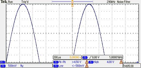
19 TRIGGER (cont.) 19 Scope-Gen_Handout_part_II_v2.2_FA16.doc FilterVu (adjustable low pass filter) 1) Push the FilterVu button Default FilterVu Settings: Noise Filter Off Noise Filter (Foreground) = 70 MHz. Glitch Capture Background: On 290kHz. 2) Turn Multipurpose a knob CCW to change the Noise Filter (Foreground) (LCD_A) to 290KHz. from 70MHz. (Filter Vu button lights up green.) 290kHz. 3) Set Glitch Capture Background (LCD_B) to Off
20 1) Press the Menu Off button once. 20 Scope-Gen_Handout_part_II_v2.2_FA16.doc v1 v2 v3 v1 v2 v3 h1 h2 t1 t2 t3 freq. Actual Time Vertical Section v1. Channel # v2. Volts/div value v3. Bandwidth limit on Horizontal Section h1. Horiz. scale: (sec/div) h2. Horiz. delay Trigger Section t1. Channel t2. Slope t3 Level (volts) 2) The waveform obtained should look exactly like the one shown above. 3) Check that the sinewave scope p-p value is 2V/div x 4 div = 1 khz. as indicated on the generator display.
. 2.")
 LCD #: A 3) For EET 101 Press To Setup1 (LCD_C) B For EET 121 Press To Setup2 (LCD_D) C D For EGR 103")
 For EET 232 Press more- (LCD_E) then, Press To Setup5 (LCD_C) LCD #: A B 2.")
21 21 Scope-Gen_Handout_part_II_v2.2_FA16.doc SAVE SETUP To Save Scope Settings: 1. Press Save/Recall Menu button (below LCD screen). 2. Press Save Setup (LCD_3) (Activates softkeys menu on right side of LCD.) LCD #: A 3) For EET 101 Press To Setup1 (LCD_C) B For EET 121 Press To Setup2 (LCD_D) C D For EGR 103 Press more- (LCD_E) then, Press To Setup3 (LCD_A) E For EET 131 Press more- (LCD_E) then, Press To Setup4 (LCD_B) For EET 232 Press more- (LCD_E) then, Press To Setup5 (LCD_C) LCD #: A B 2. If replacing a previously saved setup, (as indicated by an older date, Press LCD E. in lower rt. corner. to overwrite.. C D 3. Press Menu Off, twice. E
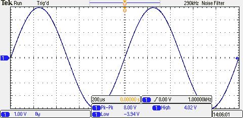
22 22 Scope-Gen_Handout_part_II_v2.2_FA16.doc AC MEASUREMENTS (A) AC PEAK VOLTAGE MEASUREMENTS: For best accuracy, want as large a sinewave as possible w/o overshooting the LCD display, by adjusting the vertical sensitivity (V/div). The peak voltage can then be determined from: (Vp) = Deflection Peak (# div.) * Vertical Sensitivity (V/div.) To Interpolate between div: Hint: Move Horiz. Position so Top of Sinewave is in Middle of LCD, so can read the sub div. Note: There are 5 sub div. vertically. Each is 0.2 div. Vpk = 2 div * 2V/div = 4V Vp-p = 4 div * 2V/div = 8V 0 V For Vp-p measurements, lower waveform so bottom of wave touches bottom graticule. Vpk = 2 div * 2V/div = 4V 0 V
23 23 Scope-Gen_Handout_part_II_v2.2_FA16.doc (B) FREQUENCY MEASUREMENTS The oscilloscope can be used to measure the output frequency of an audio oscillator or function generator using the horizontal sweep rate to determine it s period. Then use the equation: Frequency (F) = 1 / T (period measured in seconds) To measure the Period of the desired waveform: Calculate the number of divisions required to display one complete cycle on the horizontal axis. 1 period (seconds) = T = (# of div for 1 cycle)* [horiz. scale (sec/div)] Note: There are 5 sub div. Horizontally. Each is 0.2 div. Note: For an accurate time or frequency measurement it is best to have between 1 to 2 sinewaves displayed. New Trigger point (relocated from the center) Trigger Level indicator One cycle = 5 div * 200 us/div = 1000 us = 1 ms. F = 1/T = 1/1ms = 1000 Hz. one cycle Waveform crosses intersection of Trigger Level (0V) and Trigger point Trigger info: Source Slope Level Freq. STOP here! Begin Lab.
24 24 Scope-Gen_Handout_part_II_v2.2_FA16.doc STOP here! Begin Lab. AUTOMATIC MEASUREMENTS SETUP The MSO2004B can display up to four selected measurements simultaneously. Any four measurements can be displayed from among a list of 30 possible. In addition to selecting a desired measurement, the source for that measurement must also be set if different from the default source. To Add Measurements 1. Press 1 in Ch. 1 section before press Measure button 2. Press Measure button at Top Right Center of Scope. 3. Press LCD_1 Add Measurement Confirm Source is Ch.1 (LCD_B). 4, Add Measurements: a. Rotate Multipurpose a knob (center top) to pick desired measurement. b. Press Add Measurement (LCD_E) for one of the parameters shown below. Max (Vo-p), Peak to Peak (Vp-p) Period Frequency b. Press LCD_E to Add the measurement. 5. Repeat Steps 4a & 4b to add up to four measurements. 6. Press Menu Off button 2 times.


. LCD # s 1 2 3 4 5 6 7 2.")
25 25 Scope-Gen_Handout_part_II_v2.2_FA16.doc To Remove Measurements Note: If 4 measurements are already displayed, one will need to be removed before one is added. In case four are displayed, the procedure to remove a measurement is as follows: You can remove any selected measurement (LCD_A, B, C, D) or all selected measurements (Remove All) (LCD_E) 1. Press Measure button to display the Measure menu (below). LCD # s Press Remove Measurement (LCD_2) (Remove Measurement menu on right should appear) 3. Press LCD_A, or B, or C, or D to remove an unwanted measurement, or E to Remove All. LCD # s: A B 4. Then, go to previous pg. to Add Measurement(s) C D E
 If only one channel is ON, the default source is the active channel.")
 5.")
26 26 Scope-Gen_Handout_part_II_v2.2_FA16.doc ADD MEASUREMENTS 1. Press Add Measurement (LCD_1). Notice Measurements menu on LCD screen. 2. Check that the source is correct, usually 1 (LCD_B) If only one channel is ON, the default source is the active channel. If more than one channel is ON, the source can be selected by turning the Multipurpose knob b. 3. Select the 1 st desired measurement, Frequency, by scrolling up or down the list by turning the Multipurpose knob a until Frequency is highlighted. 4. Press OK Add Measurement (LCD _E) 5. Select the 2 nd desired measurement, Period, by scrolling up or down the list by turning Multipurpose knob a until Period is highlighted. 6. Press OK Add Measurement (LCD _E) 7. Repeat steps 5 & 6 for the 3 rd & 4 th measurements of Peak to Peak (for Vp-p), and Max (for Vpk). 8. Press Menu Off to remove menu covering the 4 measurements 9. (OPTIONAL) Alternately, all (30) measurements may be displayed all at once on the screen by selecting Snapshot All Meas. (LCD_E) then Press OK. (obscures most of the screen)
 or < (too negative, below the screen) symbol will be displayed before the value in the measurements box.")
27 27 Scope-Gen_Handout_part_II_v2.2_FA16.doc Note: If a complete waveform cannot be displayed or is beyond the screen borders, auto measurements cannot be made. In that case a > (too positive, above the screen) or < (too negative, below the screen) symbol will be displayed before the value in the measurements box. In the graphic above, the vertical scale is too small to allow the entire waveform to be displayed on the screen. To achieve an auto measurement, increase the vertical scale to fit the entire waveform vertically. In the above example less than one cycle is displayed To achieve an auto measurements, increase the horizontal scale to allow at least 1 to 2 cycles to be displayed. Note the ----Hz? Meas. value. Also, the voltage meas. are correct for only the displayed section of the waveform.
 This oscilloscope allow you to save a screen image of the displayed waveform, including the vertical, and horizontal settings, as well as any previously")
28 28 Scope-Gen_Handout_part_II_v2.2_FA16.doc SAVING A SCREEN IMAGE (to USB flash drive) This oscilloscope allow you to save a screen image of the displayed waveform, including the vertical, and horizontal settings, as well as any previously set up measurements. Many of the waveform images in this document were saved this way. The function will not, however, save any on-screen menus. The files are relatively small at less than 10kB. To save an image, 1) Plug a USB flash drive into the USB port on the front panel (see graphic below.) 2) Press the Save /Recall - Menu button. 3) Push the Save Screen Image button (LCD_1) 4) File Format (LCD_A) make sure.png (a standard graphics format) Is highlighted. 5) Make sure Ink Saver in On (LCD_B) (This changes the saved image screen background from black to white) 6) Press (LCD_E) OK Save Screen Image 7) After image has been saved, < 15 sec, remove the USB drive. (No uninstall required.) 8) If Assign (LCD_6) is set to Save to Image, then you just need to press the Save button to save additional images (skipping steps 2 thru 6). A new incrementally numbered file will be created on the USB drive for each image.
29 29 Scope-Gen_Handout_part_II_v2.2_FA16.doc OPTIONAL DC Measurements Use the scope to measure dc voltage levels: 1. Press the desired channel ( 1 or 2 ). 2. Set Coupling (LCD_1) to DC (In the AC Coupling mode, a capacitor blocks the DC component from the screen.) 3. Place the scope leads across the unknown DC level and use the following equation to determine the dc level: DC Level (V) = Vertical Deflection (#div.) * Vertical scale (V/div.)


30 30 Scope-Gen_Handout_part_II_v2.2_FA16.doc OPTIONAL OSCILLOSCOPE MEASUREMENTS USING THE CURSORS PERIOD Press Cursors and turn the Multipurpose a, and b. knobs to adjust the cursors to coincide with a one period interval of the waveform. 1 period V a V b ΔV a = V a ; b = V b ΔV = V a -V b The difference in Time and difference in voltage between a & b can be read from the cursor box: ta tb = Period (T): Δ1.01ms. AC with DC OFFSET The waveform below is an example of a 1000 Hz. sinewave, 6Vp-p with a +12 Vdc offset. Note that the 0V point has been adjusted to the bottom graticule to allow for the maximum vertical waveform display. Pk-Pk (Vp-p) Max (Vmax) Min (Vmin) 0 V
 Press the Cursors button a cursor b cursor 0 V Turn Multipurpose a knob to move the vertical a cursor left or right to position the crosshair at the")
31 31 Scope-Gen_Handout_part_II_v2.2_FA16.doc OPTIONAL PEAK to PEAK VOLTAGE (Vp-p or Va-Vb ) Press the Cursors button a cursor b cursor 0 V Turn Multipurpose a knob to move the vertical a cursor left or right to position the crosshair at the waveform max. Turn Multipurpose b knob to move the vertical b cursor left or right to position the crosshair at the waveform min. Read Vpk in the cursor box. a = Δ15.1V (~15V). and Vmin in the cursor box. b = Δ8.96 V (~9V) ( Δ means the difference or change in voltage ) To link the cursors so they move together (when turning Multipurpose a, only), press the Select button (notice the LCD box indicates Cursors Linked The Select button (located below Multipurpose a knob) will toggle the cursors between being linked and being independent.
32 32 Scope-Gen_Handout_part_II_v2.2_FA16.doc


33 33 Scope-Gen_Handout_part_II_v2.2_FA16.doc Vpk = 3.2 div * 1V/div = 3.2V For a more accurate meas. increase sensitivity (decrease vertical scale). Vpk = 6.4 div * 500mV/div = 3.2V
Burlington County College INSTRUCTION GUIDE. for the. Hewlett Packard. FUNCTION GENERATOR Model #33120A. and. Tektronix
 v1.2 Burlington County College INSTRUCTION GUIDE for the Hewlett Packard FUNCTION GENERATOR Model #33120A and Tektronix OSCILLOSCOPE Model #MSO2004B Summer 2014 Pg. 2 Scope-Gen Handout_pgs1-8_v1.2_SU14.doc
University of Utah Electrical & Computer Engineering Department ECE1050/1060 Oscilloscope
 University of Utah Electrical & Computer Engineering Department ECE1050/1060 Oscilloscope Name:, A. Stolp, 2/2/00 rev, 9/15/03 NOTE: This is a fill-in-the-blanks lab. No notebook is required. You are encouraged
Electrical and Electronic Laboratory Faculty of Engineering Chulalongkorn University. Cathode-Ray Oscilloscope (CRO)
") 2141274 Electrical and Electronic Laboratory Faculty of Engineering Chulalongkorn University Cathode-Ray Oscilloscope (CRO) Objectives You will be able to use an oscilloscope to measure voltage, frequency
2141274 Electrical and Electronic Laboratory Faculty of Engineering Chulalongkorn University Cathode-Ray Oscilloscope (CRO) Objectives You will be able to use an oscilloscope to measure voltage, frequency
S op o e p C on o t n rol o s L arni n n i g n g O bj b e j ctiv i e v s
 ET 150 Scope Controls Learning Objectives In this lesson you will: learn the location and function of oscilloscope controls. see block diagrams of analog and digital oscilloscopes. see how different input
Digital Storage Oscilloscopes 2550 Series
 Data Sheet Digital Storage Oscilloscopes 2550 Series The 2550 series digital storage oscilloscopes provide high performance and value in 2-channel and 4-channel configurations. With bandwidth from 70 MHz
OSCILLOSCOPE AND DIGITAL MULTIMETER
 Exp. No #0 OSCILLOSCOPE AND DIGITAL MULTIMETER Date: OBJECTIVE The purpose of the experiment is to understand the operation of cathode ray oscilloscope (CRO) and to become familiar with its usage. Also
University of Utah Electrical Engineering Department EE1050/1060 Oscilloscope. Name:, Lab TA:
 University of Utah Electrical Engineering Department EE1050/1060 Oscilloscope Name:, Lab TA: A. Stolp, 2/2/00 rev, 9/14/00 NOTE: This is a fill-in-the-blanks lab. No notebook is required. You are encouraged
ME EN 363 ELEMENTARY INSTRUMENTATION Lab: Basic Lab Instruments and Data Acquisition
 ME EN 363 ELEMENTARY INSTRUMENTATION Lab: Basic Lab Instruments and Data Acquisition INTRODUCTION Many sensors produce continuous voltage signals. In this lab, you will learn about some common methods
RIGOL. Data Sheet. DS1000B Series Digital Oscilloscopes DS1074B, DS1104B, DS1204B. Product Overview. Easy to Use Design. Applications.
 RIGOL Data Sheet Product Overview DS1000B series oscilloscopes are designed with four analog channels and 1 external trigger channel, which can capture multi-channel signal simultaneously and meet industrial
Beginners How to Test DSO138mini
 Beginners How to Test DSO138mini You have finished assembling your DSO138mini kit. You may be anxious to see it works. But you might not be familiar with oscilloscope and you could encounter unexpected
Oscilloscope Guide Tektronix TDS3034B & TDS3052B
 Tektronix TDS3034B & TDS3052B Version 2008-Jan-1 Dept. of Electrical & Computer Engineering Portland State University Copyright 2008 Portland State University 1 Basic Information This guide provides basic
Reference. TDS7000 Series Digital Phosphor Oscilloscopes
 Reference TDS7000 Series Digital Phosphor Oscilloscopes 07-070-00 0707000 To Use the Front Panel You can use the dedicated, front-panel knobs and buttons to do the most common operations. Turn INTENSITY
Using an oscilloscope - The Hameg 203-6
 Using an oscilloscope - The Hameg 203-6 What does an oscilloscope do? Setting up How does an oscilloscope work? Other oscilloscope controls Connecting a function generator Microphones audio signals and
Introduction to the oscilloscope and digital data acquisition
 Introduction to the oscilloscope and digital data acquisition Eric D. Black California Institute of Technology v1.1 There are a certain number of essential tools that are so widely used that every aspiring
BME 3512 Biomedical Laboratory Equipment List
 BME 3512 Biomedical Laboratory Equipment List Agilent E3630A DC Power Supply Agilent 54622A Digital Oscilloscope Agilent 33120A Function / Waveform Generator APPA 95 Digital Multimeter Component Layout
Working with a Tektronix TDS 3012B Oscilloscope EE 310: ELECTRONIC CIRCUIT DESIGN I
 Working with a Tektronix TDS 3012B Oscilloscope EE 310: ELECTRONIC CIRCUIT DESIGN I Prepared by: Kyle Botteon Questions? kyle.botteon@psu.edu 2 Background Information Recall that oscilloscopes (scopes)
Agilent 6000 Series Oscilloscope Demo Guide
 Agilent 6000 Series Oscilloscope Demo Guide Agilent 6000 Series Oscilloscope Demo Guide A series of portable oscilloscopes for today s and tomorrow s projects. In the next few minutes you will experience
Errata. Title & Document Type: Manual Part Number: Revision Date: HP References in this Manual
 Errata Title & Document Type: Manual Part Number: Revision Date: HP References in this Manual This manual may contain references to HP or Hewlett-Packard. Please note that Hewlett- Packard's former test
Technical Reference. TDS 684A, TDS 744A, & TDS 784A Digitizing Oscilloscope Performance Verification and Specifications
 Technical Reference TDS 684A, TDS 744A, & TDS 784A Digitizing Oscilloscope Performance Verification and Specifications 070-8990-04 Please check for change information at the rear of this manual. Fifth
2016 RIGOL TECHNOLOGIES, INC.
 RIGOL Data Sheet Product Overview DS1000B series oscilloscopes are designed with four analog channels and 1 external trigger channel, which can capture multi-channel signal simultaneously and meet industrial
PicoScope 6407 Digitizer
 YE AR PicoScope 6407 Digitizer HIGH PERFORMANCE USB DIGITIZER Programmable and Powerful 1 GHz bandwidth 1 GS buffer size 5 GS/s real-time sampling Advanced digital triggers Built-in function generator
NanoGiant Oscilloscope/Function-Generator Program. Getting Started
 Getting Started Page 1 of 17 NanoGiant Oscilloscope/Function-Generator Program Getting Started This NanoGiant Oscilloscope program gives you a small impression of the capabilities of the NanoGiant multi-purpose
Overview. Know Your Oscilloscope. Front Panel. Rear Panel. Sharing Agilent s Resources with Engineering Educators
 Know Your Oscilloscope Overview Front Panel Sharing Agilent s Resources with Engineering Educators www.educatorscorner.com Horizontal (time) controls Run control Special purpose menus/controls Trigger
Agilent DSO5014A Oscilloscope Tutorial
 Contents UNIVERSITY OF CALIFORNIA AT BERKELEY College of Engineering Department of Electrical Engineering and Computer Sciences EE105 Lab Experiments Agilent DSO5014A Oscilloscope Tutorial 1 Introduction
SDS1000C Specifications
 SDS1000C Specifications File Version V1.2 Siglent technology Co., Ltd CHARACTERISTIC: The highest Single real-time sampling rate can be up to 500MHzsa/s; Equivalent sampling rate is up to 10GSa/s. Memory
Fluke /
 Fluke 190-104/190-204 ScopeMeter 190 Series II Service Manual PN 4822 872 05405 March 2011 2011 Fluke Corporation, All rights reserved. Printed in the Netherlands All product names are trademarks of their
2 MHz Lock-In Amplifier
 2 MHz Lock-In Amplifier SR865 2 MHz dual phase lock-in amplifier SR865 2 MHz Lock-In Amplifier 1 mhz to 2 MHz frequency range Dual reference mode Low-noise current and voltage inputs Touchscreen data display
Digitizing Oscilloscopes
 Digitizing Oscilloscopes This document is meant to be a reference to the operation of the digitizing oscilloscopes available in the laboratories. Major topics will be covered, but not all the features
Manual Supplement. This supplement contains information necessary to ensure the accuracy of the above manual.
 Manual Title: 9500B Users Supplement Issue: 2 Part Number: 1625019 Issue Date: 9/06 Print Date: October 2005 Page Count: 6 Version 11 This supplement contains information necessary to ensure the accuracy
TDS 520B, TDS 540B, TDS 620B, TDS 644B, TDS 680B, TDS 684B, TDS 724A, TDS 744A, & TDS 784A
 Technical Reference TDS 520B, TDS 540B, TDS 620B, TDS 644B, TDS 680B, TDS 684B, TDS 724A, TDS 744A, & TDS 784A Digitizing Oscilloscopes Performance Verification and Specifications 070-9384-01 Copyright
imso-104 Manual Revised July 19, 2012
 imso-104 Manual Section 1 Getting Started SAFETY 1.10 Quickstart Guide 1.20 SAFETY 1.30 Compatibility 1.31 Hardware 1.32 Software Section 2 How it works 2.10 Menus 2.20 Analog Channel 2.21 On / Off 2.22
50 MHz Digital Storage Oscilloscope
 DSC-5300 50 MHz Digital Storage Oscilloscope Applications The DSC-5300 Series Signal Generators are ideally suited for applications where value and quality are equally important such as for: zeducational
PicoScope 6407 Digitizer
 YE AR HIGH PERFORMANCE USB DIGITIZER Programmable and Powerful 1 GHz bandwidth 1 GS buffer size 5 GS/s real-time sampling Advanced digital triggers Built-in function generator USB-connected Signals Analysis
imso-104 Manual Revised August 5, 2011
 imso-104 Manual Revised August 5, 2011 Section 1 Getting Started SAFETY 1.10 Quickstart Guide 1.20 SAFETY 1.30 Compatibility 1.31 Hardware 1.32 Software Section 2 How it works 2.10 Menus 2.20 Analog Channel
DataSheet. SDS1000DL Series Digital Oscilloscope
 DataSheet SDS1000DL Series Digital Oscilloscope CHARACTERISTIC: The highest Single real-time sampling rate can be up to 500MHzsa/s; Equivalent sampling rate is up to 50GSa/s. Memory Depth: 32Kpts Trigger
Digitizing Oscilloscopes (2009)
") Digitizing Oscilloscopes (2009) This document is meant to be a reference to the operation of the digitizing oscilloscopes available in the laboratories. Major topics will be covered, but not all the features
Digitizing Oscilloscopes (2009) This document is meant to be a reference to the operation of the digitizing oscilloscopes available in the laboratories. Major topics will be covered, but not all the features
MP212 Principles of Audio Technology II
 MP212 Principles of Audio Technology II Black Box Analysis Workstations Version 2.0, 11/20/06 revised JMC Copyright 2006 Berklee College of Music. All rights reserved. Acrobat Reader 6.0 or higher required
Quick Start. RSHS1000 Series Handheld Digital Oscilloscope
 Quick Start RSHS1000 Series Handheld Digital Oscilloscope General Safety Summary Carefully read the following safety precautions to avoid personal injury and prevent damage to the instrument or any products
SDS 1072/1074CFL / SDS 1102/1104CFL SDS 1202/1204CFL / SDS 1302/1304CFL Digital Storage Oscilloscopes 70MHz / 100MHz / 200MHz /300MHz
 SDS 1072/1074CFL / SDS 1102/1104CFL SDS 1202/1204CFL / SDS 1302/1304CFL Digital Storage Oscilloscopes 70MHz / 100MHz / 200MHz /300MHz Features 500MSa/s & 1GSa/s Sampling Rate 2 Channels / 4 Channels 7
PRELIMINARY INFORMATION. Professional Signal Generation and Monitoring Options for RIFEforLIFE Research Equipment
 Integrated Component Options Professional Signal Generation and Monitoring Options for RIFEforLIFE Research Equipment PRELIMINARY INFORMATION SquareGENpro is the latest and most versatile of the frequency
DataSheet SDS1000CFL Series Digital Oscilloscope
 DataSheet SDS1000CFL Series Digital Oscilloscope CHARACTERISTIC: The volume of the oscilloscope is cabinet and it is portable 7 Color TFT LCD display 2/4 channels, Bandwidth: 70MHz-300 MHz Single real-time
Digital Delay / Pulse Generator DG535 Digital delay and pulse generator (4-channel)
") Digital Delay / Pulse Generator Digital delay and pulse generator (4-channel) Digital Delay/Pulse Generator Four independent delay channels Two fully defined pulse channels 5 ps delay resolution 50 ps
Digital Delay / Pulse Generator Digital delay and pulse generator (4-channel) Digital Delay/Pulse Generator Four independent delay channels Two fully defined pulse channels 5 ps delay resolution 50 ps
WAVEJET 300 SERIES OSCILLOSCOPES. New Cover to Come. Unmatched Performance, Portability, and Value
 WAVEJET 300 SERIES OSCILLOSCOPES New Cover to Come Unmatched Performance, Portability, and Value ALL THE TOOLS YOU NEED Automatic Measurements Save time making measurements on your signals by using the
Agilent Technologies 54522A
 Agilent Technologies 54522A Data Sheet Product Specifications General Specifications Maximum Sample Rate 54522A 2 GSa/s Number of Channels (all are simultaneous acquisition) 54522A: 2 Record Length 32,768
Advanced Test Equipment Rentals ATEC (2832)
") E stablished 1981 Advanced Test Equipment Rentals www.atecorp.com 800-404-ATEC (2832) Technical Datasheet Scalar Network Analyzer Model 8003-10 MHz to 40 GHz The Giga-tronics Model 8003 Precision Scalar
E stablished 1981 Advanced Test Equipment Rentals www.atecorp.com 800-404-ATEC (2832) Technical Datasheet Scalar Network Analyzer Model 8003-10 MHz to 40 GHz The Giga-tronics Model 8003 Precision Scalar
DEPARTMENT OF THE ARMY TECHNICAL BULLETIN CALIBRATION PROCEDURE FOR AUTOMATIC VIDEO CORRECTOR TEKTRONIX, MODEL 1440 (NSN )
") DEPARTMENT OF THE ARMY TECHNICAL BULLETIN TB 11-5820-861-35 CALIBRATION PROCEDURE FOR AUTOMATIC VIDEO CORRECTOR TEKTRONIX, MODEL 1440 (NSN 5820-00-570-1978) Headquarters, Department of the Army, Washington,
DEPARTMENT OF THE ARMY TECHNICAL BULLETIN TB 11-5820-861-35 CALIBRATION PROCEDURE FOR AUTOMATIC VIDEO CORRECTOR TEKTRONIX, MODEL 1440 (NSN 5820-00-570-1978) Headquarters, Department of the Army, Washington,
User Manual. Digital Storage Oscilloscopes Models 2534, 2540 & 2542
 User Manual Digital Storage Oscilloscopes Models 2534, 2540 & 2542 General Safety Summary General Safety Summary Review the following safety precautions to avoid injury and prevent damage to this product
ScopeMeter 190 Series Specifications
 Seite 1 von 7 ScopeMeter 190 Series Specifications Product Home Features Specifications Models, Options & Accessories Oscilloscope Mode Meter Mode Recorder Mode General Specifications Oscilloscope Mode
User Manual. Digital Storage Oscilloscopes Models 2534, 2540 & General Safety Summary. Version 1.03
 General Safety Summary General Safety Summary User Manual Digital Storage Oscilloscopes Models 2534, 2540 & 2542 Review the following safety precautions to avoid injury and prevent damage to this product
PB-507. Advanced Analog & Digital Electronic Design Workstation Instruction Manual. Revision: 2/2014
 PB-507 Advanced Analog & Digital Electronic Design Workstation Instruction Manual Revision: 2/2014 Test Equipment Depot - 800.517.8431-99 Washington Street Melrose, MA 02176 TestEquipmentDepot.com 1 1
RICHLAND COLLEGE School of Engineering Business & Technology Rev. 0 W. Slonecker Rev. 1 (8/26/2012) J. Bradbury
 J. Bradbury") RICHLAND COLLEGE School of Engineering Business & Technology Rev. 0 W. Slonecker Rev. 1 (8/26/2012) J. Bradbury INTC 1307 Instrumentation Test Equipment Teaching Unit 8 Oscilloscopes Unit 8: Oscilloscopes
RICHLAND COLLEGE School of Engineering Business & Technology Rev. 0 W. Slonecker Rev. 1 (8/26/2012) J. Bradbury INTC 1307 Instrumentation Test Equipment Teaching Unit 8 Oscilloscopes Unit 8: Oscilloscopes
MSO-28 Oscilloscope, Logic Analyzer, Spectrum Analyzer
 Link Instruments Innovative Test & Measurement solutions since 1986 Store Support Oscilloscopes Logic Analyzers Pattern Generators Accessories MSO-28 Oscilloscope, Logic Analyzer, Spectrum Analyzer $ The
ADS1000C, CAL / CML Series
 ADS1000C, CAL / Series DIGITAL STORAGE OSCILLOSCOPE 25MHz, 40MHz, 60MHz, 100MHz, 150MHz, 200MHz ADS1000 C Series ADS1000 CAL/ FEATURES APPLICATIONS 500MSa/s & 1GSa/s Sampling Rate 2 Channels 7 Widescreen
Fluke 19xB-19xC-2x5C. Service Manual. ScopeMeter. models 192B,196B,199B,192C,196C,199C,215C,225C
 Fluke 19xB-19xC-2x5C ScopeMeter models 192B,196B,199B,192C,196C,199C,215C,225C Service Manual PN 4822 872 05391 September 2002, rev.2, Oct.09 2002-2009 Fluke Corporation, All rights reserved. All product
DataSheet SDS1000CML Series Digital Oscilloscope
 DataSheet SDS1000CML Series Digital Oscilloscope CHARACTERISTIC: The highest Single real-time sampling rate can be up to1gsa/s; Equivalent sampling rate is up to 50GSa/s. Memory Depth: 2Mpts Trigger types:
WAVEJET 300 SERIES OSCILLOSCOPES. Unmatched Performance, Portability, and Value
 WAVEJET 300 SERIES OSCILLOSCOPES Unmatched Performance, Portability, and Value 1 WAVEJET 300 SERIES Unique Capabilities in a Low Bandwidth Oscilloscope The WaveJet 300 Series features unmatched performance
MIE 402: WORKSHOP ON DATA ACQUISITION AND SIGNAL PROCESSING Spring 2003
 MIE 402: WORKSHOP ON DATA ACQUISITION AND SIGNAL PROCESSING Spring 2003 OBJECTIVE To become familiar with state-of-the-art digital data acquisition hardware and software. To explore common data acquisition
OS Series Handheld Digital Storage. Oscilloscope & Multimeter. User Manual
 OS Series Handheld Digital Storage Oscilloscope & Multimeter User Manual OS-1022 OS-2062 20MHz 60 MHz General Warranty We warrants that the product will be free from defects in materials and workmanship
Analog Storage Oscilloscope TS-81000/ Newly developed CCD(Charge-coupled device) scan converter tube
 scan converter tube") TS-81000 DC 1 GHz, 4 CH, 15 traces TS-80600 DC 600 MHz, 4 CH, 15 traces There is the world, only Analog can capture it! State of the art Analog Oscilloscope As technology advanced rapidly, it is getting
TS-81000 DC 1 GHz, 4 CH, 15 traces TS-80600 DC 600 MHz, 4 CH, 15 traces There is the world, only Analog can capture it! State of the art Analog Oscilloscope As technology advanced rapidly, it is getting
SMART Trigger modes like Glitch, Window and Dropout allow you to capture precisely the events of interest.
 9310A Family Digital Oscilloscopes 400 MHz Bandwidth, 100 MS/s Main Features Two and Four Channel Versions 50k, 200k and 1M Point Records DOS Compatible Floppy Disk, PCMCIA portable hard drive and Memory
MINI PC SCOPE PCSU01. User manual. test leads software download USB cable design enclosure
 MINI PC SCOPE PCSU01 User manual Features test leads software download USB cable design enclosure Specifications oscilloscope: o bandwidth: DC to 200 khz ± 3 db o input impedance: 100 ko / 20 pf o maximum
4.9 BEAM BLANKING AND PULSING OPTIONS
 4.9 BEAM BLANKING AND PULSING OPTIONS Beam Blanker BNC DESCRIPTION OF BLANKER CONTROLS Beam Blanker assembly Electron Gun Controls Blanker BNC: An input BNC on one of the 1⅓ CF flanges on the Flange Multiplexer
Advanced Skills with Oscilloscopes
 Advanced Skills with Oscilloscopes A Hands On Laboratory Guide to Oscilloscopes using the Rigol DS1104Z By: Tom Briggs, Department of Computer Science & Engineering Shippensburg University of Pennsylvania
Experiment # 4 Counters and Logic Analyzer
 EE20L - Introduction to Digital Circuits Experiment # 4. Synopsis: Experiment # 4 Counters and Logic Analyzer In this lab we will build an up-counter and a down-counter using 74LS76A - Flip Flops. The
What is oscilloscope? What an oscilloscope looks like. Oscilloscopes, accessories, applications Ján Šaliga
 Oscilloscopes, accessories, applications Ján Šaliga 2017 What is oscilloscope? The main purpose of an oscilloscope is to give an accurate visual representation of electric signals. By viewing signals displayed
Revision History. SDG2000X Firmware Revision History and Update Instructions
 Revision History Date Version Revision 2/28/2018 2.01.01.23R8 Optimized calibration and PV process on the production line. 8/29/2017 2.01.01.23R7 1. Supported system recovery from U-disk. 2. Fixed a bug
INSTRUCTION MANUAL Model 2522C. 20 MHz DIGITAL STORAGE/ANALOG OSCILLOSCOPE
 INSTRUCTION MANUAL Model 2522C 20 MHz DIGITAL STORAGE/ANALOG OSCILLOSCOPE TEST INSTRUMENT SAFETY WARNING Normal use of test equipment exposes you to a certain amount of danger from electrical shock because
Embest DSO2300. Feature. General Description:
 Embest DSO2300 Feature General Description: DSO2300 is an intelligent two-channel PC based USB digital storage oscilloscope with high performance. It runs on any USB1.1 or USB2.0 equipped PC using Windows
2510 Series Handheld Digital Storage Oscilloscopes
 Model: 2511, 2512, 2515, 2516 2510 Series Handheld Digital Storage Oscilloscopes USER MANUAL Safety Summary The following safety precautions apply to both operating and maintenance personnel and must be
Physics 123 Hints and Tips
 Physics 123 Hints and Tips Solderless Breadboards All of the analog labs and most of the digital labs will be built on the Proto-Board solderless breadboards. These provide three solderless breadboard
User Manual. GPS-1000B+ series. Digital Oscilloscope V 1.1
 User Manual GPS-1000B+ series Digital Oscilloscope V 1.1 Brief Introduction Characteristic: The volume of the oscilloscope is cabinet and it is portable 7 Color TFT LCD display 2 channels, Bandwidth:
Activity P32: Variation of Light Intensity (Light Sensor)
") Activity P32: Variation of Light Intensity (Light Sensor) Concept DataStudio ScienceWorkshop (Mac) ScienceWorkshop (Win) Illuminance P32 Vary Light.DS P54 Light Bulb Intensity P54_BULB.SWS Equipment Needed
Activity P32: Variation of Light Intensity (Light Sensor) Concept DataStudio ScienceWorkshop (Mac) ScienceWorkshop (Win) Illuminance P32 Vary Light.DS P54 Light Bulb Intensity P54_BULB.SWS Equipment Needed
SNG-2150C User s Guide
 SNG-2150C User s Guide Avcom of Virginia SNG-2150C User s Guide 7730 Whitepine Road Revision 001 Richmond, VA 23237 USA GENERAL SAFETY If one or more components of your earth station are connected to 120
Tektronix 2440 Digital Storage Oscilloscope
 Tektronix 2440 Digital Storage Oscilloscope Operation This section is composed of two subsections. The first contains basic operating information and techniques that should be understood before you attempt
Portable Performance for Debug and Validation
 WaveJet 300A Oscilloscopes 100 MHz 500 MHz Portable Performance for Debug and Validation A UNIQUE TOOLSET FOR PORTABLE OSCILLOSCOPES Key Features 100 MHz, 200 MHz, 350 MHz and 500 MHz bandwidths Sample
Experiment 13 Sampling and reconstruction
 Experiment 13 Sampling and reconstruction Preliminary discussion So far, the experiments in this manual have concentrated on communications systems that transmit analog signals. However, digital transmission
Operator s Manual. WaveJet Touch Oscilloscopes
 Operator s Manual WaveJet Touch Oscilloscopes WaveJet Touch Oscilloscopes Operator s Manual 2014 Teledyne LeCroy, Inc., All rights reserved. Unauthorized duplication of Teledyne LeCroy documentation materials
Model P2016. Dual Channel Handheld Digital Storage. Oscilloscope & Multimeter. Quick Scope Guide
 Model P2016 Dual Channel Handheld Digital Storage Oscilloscope & Multimeter Quick Scope Guide General Warranty BNC warrants that the product will be free from defects in materials and workmanship for 3
User s Manual. TDO1000/TDO2000 Series Oscilloscopes
 User s Manual TDO1000/TDO2000 Series Oscilloscopes Manual Print History The manual print history shown below lists all the printing dates and editions. The printing date changes when a new edition is released.
User Manual SDS1000CML+/SDS1000DL+ Digital Oscilloscope UM0101A-E01A SIGLENT TECHNOLOGIES CO,.LTD
 User Manual SDS1000CML+/SDS1000DL+ Digital Oscilloscope UM0101A-E01A SIGLENT TECHNOLOGIES CO,.LTD Declaration Copyright by SIGLENT TECHNOLOGIES CO,.LTD. All rights reserved. Contents in this Manual are
User Manual. Digital Oscilloscope V1.9
 User Manual Digital Oscilloscope V1.9 Declaration All rights reserved. Contents in this Manual are not allowed to copy, extract and translate before being allowed by the company. Brief Introduction Characteristic:
SC24 Magnetic Field Cancelling System
 SPICER CONSULTING SYSTEM SC24 SC24 Magnetic Field Cancelling System Makes the ambient magnetic field OK for the electron microscope Adapts to field changes within 100 µs Touch screen intelligent user interface
LeCroy Digital Oscilloscopes
 LeCroy Digital Oscilloscopes Get the Complete Picture Quick Reference Guide QUICKSTART TO SIGNAL VIEWING Quickly display a signal View with Analog Persistence 1. Connect your signal. When you use a probe,
Experiment 9A: Magnetism/The Oscilloscope
 Experiment 9A: Magnetism/The Oscilloscope (This lab s "write up" is integrated into the answer sheet. You don't need to attach a separate one.) Part I: Magnetism and Coils A. Obtain a neodymium magnet
Agilent MOI for HDMI 1.4b Cable Assembly Test Revision Jul 2012
 Revision 1.11 19-Jul 2012 Agilent Method of Implementation (MOI) for HDMI 1.4b Cable Assembly Test Using Agilent E5071C ENA Network Analyzer Option TDR 1 Table of Contents 1. Modification Record... 4 2.
Measuring with digital storage oscilloscopes
 Markus Reil, Rainer Wagner 2.2016 1MAA265-1e Educational note Measuring with digital storage oscilloscopes Educational note Products: ı R&S HMO1002 This educational note covers the theory and practice
Keysight FieldFox Microwave Analyzers
 Quick Reference Guide Contents Keysight FieldFox Microwave Analyzers Do you have everything?... 1 The Power Button and LED... 1 Battery Usage... 2 Measure Return Loss (CAT Mode)... 3 Measure 1-Port Cable
Expect to Make Waves.
 Expect to Make Waves. The New Oscilloscope Large 10.4" LCD touch screen Long capture time Extensive communication capabilities www.lecroy.com The New Oscillos From its large 10.4" LCD touch screen to its
25 MHz Digital Storage Oscilloscope
 99 Washington Street Melrose, MA 02176 Phone 781-665-1400 Toll Free 1-800-517-8431 Visit us at www.testequipmentdepot.com Model: 2530B 25 MHz Digital Storage Oscilloscope USER MANUAL Safety Summary The
SC24 Magnetic Field Cancelling System
 SPICER CONSULTING SYSTEM SC24 SC24 Magnetic Field Cancelling System Makes the ambient magnetic field OK for the electron microscope Adapts to field changes within 100 µs Touch screen intelligent user interface
Troubleshooting Your Design with Tektronix MSO and DPO Series Oscilloscopes
 Troubleshooting Your Design with Tektronix MSO and DPO Series Oscilloscopes Our thanks to Tektronix for allowing us to reprint the following article. Today s engineers and technicians face increasingly
R2001A/B/C Service Monitor Alignment Sections
 R2001A/B/C Service Monitor Alignment Sections R2001A Depot Alignment Notes R2001A Alignment Section A12 FRNT PNL INTERFACE A3 SCOPE/DVM CONTRC)L SINAD IN 3 ( 6 3 1 KHz NOTCH FIL DET»
Spectrum Analyser Basics
 Hands-On Learning Spectrum Analyser Basics Peter D. Hiscocks Syscomp Electronic Design Limited Email: phiscock@ee.ryerson.ca June 28, 2014 Introduction Figure 1: GUI Startup Screen In a previous exercise,
MAIN PCA TEST PROCEDURE DOCUMENT NUMBER:
 TEST PROCEDURE DOCUMENT NUMBER: -20 Signature Date Author J. Hoo 10-7-96 CHK J. Hoo 10-7-96 CHK - - Approved J. Hoo 10-7-96 Huntron Instruments, Inc. 1996 All rights reserved. This document may not be
Agilent 5345A Universal Counter, 500 MHz
 Agilent 5345A Universal Counter, 500 MHz Data Sheet Product Specifications Input Specifications (pulse and CW mode) 5356C Frequency Range 1.5-40 GHz Sensitivity (0-50 deg. C): 0.4-1.5 GHz -- 1.5-12.4 GHz
Dave Jones Design Phone: (607) Lake St., Owego, NY USA
 Lake St., Owego, NY USA") Manual v1.00a June 1, 2016 for firmware vers. 2.00 Dave Jones Design Phone: (607) 687-5740 34 Lake St., Owego, NY 13827 USA www.jonesvideo.com O Tool Plus - User Manual Main mode NOTE: New modules are
Manual v1.00a June 1, 2016 for firmware vers. 2.00 Dave Jones Design Phone: (607) 687-5740 34 Lake St., Owego, NY 13827 USA www.jonesvideo.com O Tool Plus - User Manual Main mode NOTE: New modules are
FREQUENCY COUNTERS TO 18 GHZ USING THE DATUM FREQUENCY STANDARD
 TECHNICAL MANUAL AF-166 INSTRUMENT CALIBRATION FREQUENCY COUNTERS TO 18 GHZ USING THE DATUM 9390-6000-34 FREQUENCY STANDARD THIS PUBLICATION SUPERSEDES NAVAIR 17-20AF-166 DATED 1 FEBRUARY 2005 DISTRIBUTION
CHAPTER 3 OSCILLOSCOPES AND SIGNAL GENERATOR
 CHAPTER 3 OSCILLOSCOPES AND SIGNAL GENERATOR OSCILLOSCOPE 3.1 Introduction The cathode ray oscilloscope (CRO) provides a visual presentation of any waveform applied to the input terminal. The oscilloscope
Model 7330 Signal Source Analyzer Dedicated Phase Noise Test System V1.02
 Model 7330 Signal Source Analyzer Dedicated Phase Noise Test System V1.02 A fully integrated high-performance cross-correlation signal source analyzer from 5 MHz to 33+ GHz Key Features Complete broadband
ENJOY YOUR BOOKS PLEASE VISIT OUR STORE FOR EVEN MORE GREAT STUFF! COPYRIGHT NOTICE ALL MATERIALS INCLUDING CD/DVD AND
 ENJOY YOUR BOOKS PLEASE VISIT OUR STORE FOR EVEN MORE GREAT STUFF! WWW.EVERYTHING4LESSSTORE.COM COPYRIGHT NOTICE ALL MATERIALS INCLUDING CD/DVD AND PDF FILES ARE COPYRIGHTED WWW.EVERYTHING4LESSSTORE.COM