Installation Instructions JMS EGT Kit 9617A & 9617B Exhaust Gas Temperature Sensor Kit for SCT Diesel Truck Tuners and Monitors
|
|
|
- Kristian McDaniel
- 5 years ago
- Views:
Transcription
 9617B - EGT Amplifier Box with Type-K connector and molded cable to Firewire.")


1 Installation Instructions JMS EGT Kit 9617A & 9617B Exhaust Gas Temperature Sensor Kit for SCT Diesel Truck Tuners and Monitors Included in the EGT kit: (4) Plastic Tie Straps for mounting (1) EGT probe with dual-ferrule 1/8" NPT fittings, RFI shielded cable, and Type-K connector (1) 9617B - EGT Amplifier Box with Type-K connector and molded cable to Firewire. Or (1) 9617A - EGT Amplifier Box with Type-K connector and 9-pin connector to Firewire cable. Step 1: Locate the exhaust manifold on the driver s side of the vehicle. On most 2003-Up Ford Trucks, the area of the manifold to be drilled and tapped is located at the rear of the exhaust manifold near the transmission. (Refer to the image below) Tech Tip: Use a generous amount of heavy grease on the drill bit and tap to capture any metal shavings or contaminates left as a result of the drilling and tapping process. Always use a small magnet after the process to ensure that you have retrieved any metal shavings prior to installation of the thermocouple. Step 2: Drill a 5/16 hole into the manifold. Tap the hole, using a 1/8 National Pipe Thread Tap (NPT). Both the drill bit and tap can be purchased from JMS via part number: JMS-EGT-INSTALL. Be sure to follow the instructions included with the tap. The tap will be tapered and you want to tap the hole only until the threads of the tap are slightly deeper than the inside of the manifold. Note: the drill, tap and grease can also be purchased at a local hardware store. Step 3: Once drilling and tapping are complete, check to make sure there are no metal shavings in the manifold. If you see shavings or contaminates, remove them before inserting the thermocouple. Install the fitting by screwing the tapered end of the fitting into the manifold. The tip of the fitting should be flush with the inside of the exhaust path, but not any deeper. Tighten the fitting with a small wrench or socket, but be sure not to over-torque the fitting. Next, insert the EGT probe and feral into the fitting so that the tip is in the center of the exhaust flow path. Tighten the top nut on the fitting just tight enough to crush the feral and keep the thermocouple firmly in position.


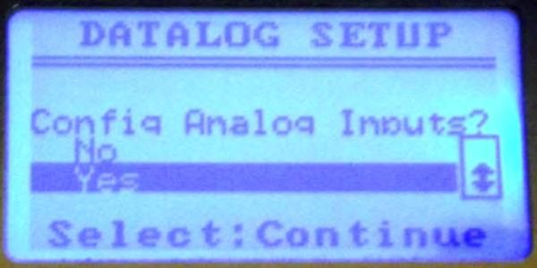
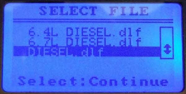
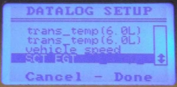
2 Step 4: Locate a place inside the cabin to mount the JMS EGT amplifier box. This can be any place you choose, but it should be kept away from any heat source and any sources of extreme vibration. Do not place near the engine or under the hood. Use the supplied tie straps and the holes in the EGT box to secure. Step 5: You will need to run the EGT sensor cable through the firewall of the vehicle, in most cases there is a seal covering an existing factory hole. Use aluminum tape or equivalent to cover the OEM hole after the EGT cable assembly has been routed into the interior. Step 6: Once the cable routing is complete, plug the EGT sensor cable with two prong Type-K connector into the amplifier box. Plug the FireWIRE analog cable into the Livewire (P/N 9600/9614) device, or the FireWIRE port on the X3 (P/N 3000/3015) or LivewireTS OBDII Plug (P/N 9XXX). For non-sct devices, plug the 9-pin connector side of the analog cable into the EGT Amplifier Box, and refer to the non-sct device instructions for splicing. SCT Handheld Tuning Device EGT Setup & Programming: Analog Notes: 1) SCT X3 and Livewire 9600 handheld tuning devices are designed to read up to 2 analog channels via a FireWIRE analog cable, the JMS EGT sensor kit uses Channel 2 (Channel 1 is not used with this kit). 2) SCT LivewireTS is designed to read a single analog signal via the FireWIRE port. On the Livewire TS the JMS EGT sensor kit is designed to plug and play and work on Channel 7. SCT X3 (P/N 3000/3015): Step 1: Plug the FireWIRE analog cable into the port located on the top of the device. The X3 device is designed primarily for datalogging, but can display EGT in real-time. To set up the datalogging feature, please refer to the device installation instructions, and follow on-screen device options and prompts. Step 2: In the Datalog set up process you can choose a dedicated or generic diesel datalog file (.DLF) and record the sensor reading to file. Step 3: In the Monitor set up feature, you will establish the sensor type for "Channel 2" as "EGT", then "SCT EGT", for sensor output reading to the screen in real-time display. Be sure to always follow the on-screen prompts to ensure features and options are saved correctly. Screen images below show the basic steps in order.


3

 and setup to monitor analog sensor 2.")

4 Livewire (P/N 9600/9621/9625): Step 1: Plug the FireWIRE analog cable into the port located on the bottom of the device. The Livewire is designed to display various parameters and analog signals in real-time. Step 2: To set up the datalogging feature, please refer to the device installation instructions and follow on-screen device options and prompts. Step 3: In the Datalog set up process choose a dedicated diesel datalog file or another file that matches your type of vehicle (.DLF) and setup to monitor analog sensor 2. Step 4: In the "Performance Data" set up feature, you will access the "Analog Setup" feature and establish the sensor type for "Channel 2" as "EGT", then "SCT EGT", for sensor output reading to the screen in real-time display. Step 5: Next you will follow the "Monitor Setup" feature process to establish the list of parameters to display, and you will choose the "SCT EGT" analog input from the list of available items. Be sure to always follow the on-screen prompts to ensure features and options are saved correctly. Images below show the basic steps in order. LivewireTS (P/N 5015/5416): Step 1: Plug the FireWIRE analog cable into the port located on the OBDII cable near the connector (built into the cable). The LivewireTS is designed to display various parameters and analog signals in real-time. Step 2: To set up the datalogging feature, please refer to the SCT device analog monitoring installation instructions, and follow on-screen device options and prompts. Step 3: In the Datalog set up process choose a dedicated diesel datalog file or another file that matches your type of vehicle (.DLF) and setup to monitor analog sensor 7. Step 4: In the "Gauges/Datalog" set up feature, choose your pre-loaded vehicle file, which starts the monitor. Note how the single-tap and double-tap navigation works, single-tap to view the menu, and double-tap to to edit gauges.


.")


5 Step 5: Double-tap one of the 3 signals displayed on the default monitor to enter parameter edit mode. Single tap on the "Item" field, then press and hold on the screen to scroll (unlike a smart phone you have to press firmly on the screen, hold and then move the scree up or down to display additional items). Analog Inputs are at the very bottom of the item selection menu, select "Analog Input 7", and tap "Continue". Single-tap on the "Unit" field next and select the "Unit" type as "SCT EGT", and tap "Continue". Once the analog input is set up, you can tap "Approve" to take you back to the monitor and view the EGT signal in real-time. Be sure to always follow the on-screen prompts to ensure features and options are saved correctly. Images below show the basic steps in order from left to right.

. This instability is normal, once the EGT gets above 200F the instability issue goes away.")


6 Analog Monitoring Notes and Troubleshooting: SCT states in the LivewireTS instructions that the voltage below 0.23 volts is not accurate for analog inputs 5 and 6, this is also true for analog input 7. As a result, there is some instability in the EGT reading when the exhaust gas temperature is below 200 degrees (+-50F). This instability is normal, once the EGT gets above 200F the instability issue goes away. We have been told that the Livewire TS will be corrected in a future 2013 build to address this issue. Due to different suppliers of FireWIRE cables and the inconsistency in manufacturing, we cannot give you a color coded pin-out diagram for the cable. You can tone out the pins on the connector if needed via the attached wiring diagram.. If display on your X3 device is not reading a EGT value, unplug and reinsert FireWIRE cable. If the EGT FireWIRE cable is not plugged into the SCT device, the monitor will display a low temp value. If the EGT sensor is not plugged into the EGT amplifier box, the monitor will display a high temp value.
Choose the analog portthatyouwish to use.")
Use a DigitalVoltOhm M eterto figure outwhich colored wire is connected to each Firewire pin.")
ConnectJM S EGT FireW ire Pin 1to SCT 10 pin -External5V (Red W ire) 5)ConnectJM S EGT FireW ire Pin 2 to SCT 10 pin -GROUND (BlackW ire)")
![6)ConnectJM S EGT FireW ire Pin 5 to SCT 10 pin -Analog 1-6 7)ConnectJM S EGT FireW ire Pin 6 to SCT 10 pin -GROUND (BlackW ire [Optional]) N ote:m](/docs-images/87/95409330/images/7-3.jpg "inim um voltage forsct analog 5,6 & 7 is:0.23v DC M inim um voltage forsct analog 1,2,3 & 4 is:0.")

7 JM S 9617 EGT Kit-Cable Reference RevD -04/30/13 Typicalythe onlytim e thatyou would connectthe JM S EGT to the SCT 10 pin is ifyou wantto m onitor the EGT on aanalog Portotherthan Port7.Orifyou are connecting the JM S EGT to the SCT itsx. 1)Choose the analog portthatyouwish to use.(forexam ple Analog 1-W hite on SCT 10 pin) 2)Cutthe JM S 9617 EGT Cable 4 inches from the Firewire Cable and pulthe colored cables out. 3)Use a DigitalVoltOhm M eterto figure outwhich colored wire is connected to each Firewire pin. Step 3 has to occurdue to suppliervariations in wire colors. 4)ConnectJM S EGT FireW ire Pin 1to SCT 10 pin -External5V (Red W ire) 5)ConnectJM S EGT FireW ire Pin 2 to SCT 10 pin -GROUND (BlackW ire) 6)ConnectJM S EGT FireW ire Pin 5 to SCT 10 pin -Analog 1-6 7)ConnectJM S EGT FireW ire Pin 6 to SCT 10 pin -GROUND (BlackW ire [Optional]) N ote:m inim um voltage forsct analog 5,6 & 7 is:0.23v DC M inim um voltage forsct analog 1,2,3 & 4 is:0.08v DC M in voltage m eans:voltage wilslightlyfluctuate ifyou are m onitoring a voltage thatis less than the m ininim um. Exam ple:egt Tem ps BELOW 200F m ayfluctuate +-50F. A SCT productchange laterin m id-2013 wilcorrect the slightvoltage fluctuation atverylow voltage levels. JM S has two differentegt Cable Options. 9617A -utilizes adb9 cable to Firewire (shown). 9617B -utilizes an integrated cable on the EGT boxside to Firewire. Both wire the sam e. Firewire Pin 1=+5V,Pin 2 =Ground,Pin 5 =EGT Signal(0-5v),Pin 6 =EGT SignalGround
Cellular Signal Booster
 Drive 4G-X Cellular Signal Booster THE ALUMINUM CASING OF YOUR SIGNAL BOOSTER!! WILL ADJUST TO THE TEMPERATURE OF ITS ENVIRONMENT, BUT IS DESIGNED TO PROTECT THE SIGNAL BOOSTER TECHNOLOGY. FOR EXAMPLE,
Product Manual MNX10015 / REV C MODEL SB142, SB242. Dual Output Series Switch Boxes
 Product Manual MNX10015 / REV C MODEL SB142, SB242 Dual Output Series Switch Boxes Contents Section I Overview Introduction.... 2 Description... 2 Section II Installation Mounting... 3 Electrical Connections...
NewScope-7A Operating Manual
 2016 SIMMCONN Labs, LLC All rights reserved NewScope-7A Operating Manual Preliminary May 13, 2017 NewScope-7A Operating Manual 1 Introduction... 3 1.1 Kit compatibility... 3 2 Initial Inspection... 3 3
2000 Series Weather Stations Analog Temperature / RH Sensor Upgrade Kit PRODUCT MANUAL KIT # 3613WDU
 2000 Series Weather Stations Analog Temperature / RH Sensor Upgrade Kit PRODUCT MANUAL KIT # 3613WDU 1 The 3613WDU Analog Temperature / RH Sensor Upgrade Kit is used to upgrade Watchdog 2000 Series Weather
AUDIO ROOF KIT P/N , , APPLICATION BEFORE YOU BEGIN KIT CONTENTS. Instr Rev Page 1 of 6
 AUDIO ROOF KIT P/N 2882064, 2882065, 2882066 APPLICATION Verify accessory fitment at Polaris.com. BEFORE YOU BEGIN Read these instructions and check to be sure all parts and tools are accounted for. Please
In-Ceiling Electric Motorized Front Projection Screen Evanesce Series. User s Guide
 In-Ceiling Electric Motorized Front Projection Screen Evanesce Series User s Guide Important Safety & Warning Precautions Make sure to read this user s guide and follow the procedures below. Caution: The
Gazer VI700A-SYNC2 and VI700W- SYNC2 INSTALLATION MANUAL
 Gazer VI700A-SYNC2 and VI700W- SYNC2 INSTALLATION MANUAL Contents List of compatible cars... 3 Package contents... 4 Special information... 6 Car interior disassembly and connection guide for Ford Focus...
Safety Information. Camera System. If you back up while looking only at the monitor, you may cause damage or injury. Always back up slowly.
 Table of Contents Introduction...3 Safety Information...4-6 Before Beginning Installation...7 Installation Guide...8 Wiring Camera & Monitor...9-10 Replacement Installation Diagram...11 Clip-On Installation
GENUINE PARTS CAUTION
 GENUINE PARTS SATELLITE RADIO INSTALLATION INSTRUCTIONS 1. DESCRIPTION: SATELLITE RADIO SYSTEM 2. PART NUMBERS: XM tuner kit 999U9-NV003 XM antenna kit 999U9-VR000 Sirius tuner kit 999U9-NV004 Sirius antenna
USER MANUAL FOR THE ANALOGIC GAUGE FIRMWARE VERSION 1.1
 by USER MANUAL FOR THE ANALOGIC GAUGE FIRMWARE VERSION 1.1 www.aeroforcetech.com Made in the USA! WARNING Vehicle operator should focus primary attention to the road while using the Interceptor. The information
USER MANUAL FOR THE ANALOGIC GAUGE FIRMWARE VERSION 1.0
 by USER MANUAL FOR THE ANALOGIC GAUGE FIRMWARE VERSION 1.0 www.aeroforcetech.com Made in the USA! WARNING Vehicle operator should focus primary attention to the road while using the Interceptor. The information
Ford 6.4L Powerstroke Installation Instructions
 31 December 2008 BD Ford 6.4L Powerstroke X-Tuner # 1054871 1 ULTRA X-TUNER POWER PROGRAMMER Ford 6.4L Powerstroke Installation Instructions 1054871 Ford 6.4L Powerstroke F250 / F350 / F450 2008+ *** READ
VITEK VTM-TLM191 VTM-TLM240
 VTM-TLM191 VTM-TLM240 19 & 24 Professional LED Monitors with HDMI, VGA, and Looping BNC VITEK FEATURES 19 & 24 Wide Screen LED Display Panel HDMI, VGA, and Looping BNC Composite Video Inputs & Stereo Audio
ELECTRONICS CORP. VOD715 Drop Down Video Monitor with DVD FM SELECT PAUSE L R. Installation Guide
 IR VIDEO INPUT AUDIO L R ELECTRONICS CORP. VOD715 Drop Down Video Monitor with DVD PAUSE REV FWD SOURCE ON OFF AUTO VOLUME FM SELECT S HEADPHONES Installation Guide Important Notice It is unlawful in most
VT320X Large Screen Outdoor LCD
 Solutions for Demanding Applications VARTECH S Y S T E M S I N C. Industrial CRT and Flat Panel Displays VT320X Large Screen Outdoor LCD User s Guide Read these instructions completely before attempting
CN Remove the scanner assembly (X476 and X576 models) and all doors/covers.
 and all doors/covers.") CN598-67045 www.hp.com/support IMPORTANT: Ensure the product firmware is upgraded to at least version 1336MR before performing this repair procedure. If the firmware upgrade cannot be completed, contact
CN598-67045 www.hp.com/support IMPORTANT: Ensure the product firmware is upgraded to at least version 1336MR before performing this repair procedure. If the firmware upgrade cannot be completed, contact
Gazer VI700A-SYNC/IN and VI700W- SYNC/IN INSTALLATION MANUAL
 Gazer VI700A-SYNC/IN and VI700W- SYNC/IN INSTALLATION MANUAL Contents List of compatible cars... 3 Package contents... 4 Special information... 6 Car interior disassembly and connection guide for Ford
EAGLE RE-1 CONTROLLER
 EAGLE RE-1 CONTROLLER For Use On ALL MotoSAT Mounts Supported Systems HD SL5 DirecTV HD DP3 Dish Network HD SC2 SHAW HD DP3 BELL TV EXECUTIVE 18" DirecTV 101 Dish Network 119 MSC-60 SHAW MD-500 Dish Network
SIR-GM1 GM CLASS-2 BUS COMPATIBLE SIRIUS SATELLITE RADIO TUNER
 SIR-GM1 GM CLASS-2 BUS COMPATIBLE SIRIUS SATELLITE RADIO TUNER Installation Guide Congratulations on your purchase of the SIR-GM1 the GM Compatible SIRIUS Satellite Radio Tuner! Your SIR-GM1 is designed
ELECTRONICS CORP. VOD1021/VOD1022 Drop Down Video TV/Monitor with DVD. Installation Guide
 ELECTRONICS CORP. VOD1021/VOD1022 Drop Down Video TV/Monitor with DVD Installation Guide Important Notice An LCD panel and/or video monitor may be installed in a motor vehicle and visible to the driver
ACUBRITE 23 SS. Manual. Stainless Steel Chassis 23" LCD Display. Content
 ACUBRITE 23 SS Stainless Steel Chassis 23" LCD Display Manual Introduction... 2 Hardware Installation... 2 The Display Timing... 5 The Display Outline Dimensions... 6 The Display Controls... 7 The Screen
MUK REAR PANEL ASSEMBLY ASSEMBLY INSTRUCTIONS
 Rev B. 13 August 2017 ASSEMBLY INSTRUCTIONS The Midnight Ultimate Keyer (MUK) consists of two functional assemblies: Rear Panel containing the interface and power connectors. Front Panel containing the
Car-Solutions.com. Warning / Caution. Warning. Caution
 Video Interface for Volkswagen Golf 7 with Discover Media Update Date 2013.11.14 Model User Guide QPI-G7-MAIN-V2.0 Firmware Date 131028 Warning / Caution Warning Caution When installing the main unit,
Warning and Safety Information. FCC Information
 Installation Manual Warning and Safety Information FCC Information This device complies with FCC Rules Part 15 Operation and is subject to the following two conditions: (1) This device may not cause harmful
TV Lift System Model CL-65 Installation Instructions
 TV Lift System Model CL-65 Installation Instructions Contact: Support@Nexus21.com Toll Free: (866) 500-5438 Phone: (480) 951-6885 Fax: (480) 951-6879 Revised: 01/17/17 Below is a parts list describing
Lynx Broadband Installation Manual for Residential Packages with a 35 db Amp Quick Start Guide (first 3 pages)
") Lynx Broadband Installation Manual for Residential Packages with a 35 db Amp Quick Start Guide (first 3 pages) 1. Be sure that your kit includes all the parts shown in the Check the Equipment section in
Lynx Broadband Installation Manual for Residential Packages with a 35 db Amp Quick Start Guide (first 3 pages) 1. Be sure that your kit includes all the parts shown in the Check the Equipment section in
apple Service Source Apple Cinema HD Display 23" LCD (ADC) 11 April Apple Computer, Inc. All rights reserved.
 11 April Apple Computer, Inc. All rights reserved.") apple Service Source Apple Cinema HD Display 23" LCD (ADC) 11 April 2003 2003 Apple Computer, Inc. All rights reserved. apple Service Source Take Apart Apple Cinema HD Display 23" LCD (ADC) 2003 Apple
apple Service Source Apple Cinema HD Display 23" LCD (ADC) 11 April 2003 2003 Apple Computer, Inc. All rights reserved. apple Service Source Take Apart Apple Cinema HD Display 23" LCD (ADC) 2003 Apple
Model#: IN-DI2MIRF 2MP Indoor Dome with True Day/Night, IR, Basic WDR, Fixed lens
 Model#: IN-DI2MIRF 2MP Indoor Dome with True Day/Night, IR, Basic WDR, Fixed lens Hardware User Manual (PoE) Ver.2013/01/17 Table of Contents 0. Precautions 3 1. Introduction 4 Package Contents...4 Features
GENUINE PARTS SATELLITE RADIO INSTALLATION INSTRUCTIONS. 1. DESCRIPTION: Satellite Radio System 2. APPLICATION: Frontier (2006~)
") GENUINE PARTS SATELLITE RADIO INSTALLATION INSTRUCTIONS 1. DESCRIPTION: Satellite Radio System 2. APPLICATION: Frontier (2006~) Xterra (2006~) 3. PART NUMBERS: XM Tuner Kit 999U9-AS003 SIRIUS Tuner Kit
GENUINE PARTS SATELLITE RADIO INSTALLATION INSTRUCTIONS 1. DESCRIPTION: Satellite Radio System 2. APPLICATION: Frontier (2006~) Xterra (2006~) 3. PART NUMBERS: XM Tuner Kit 999U9-AS003 SIRIUS Tuner Kit
Introduction. Introduction
 Introduction Introduction Note: In this user guide Pronto is used for both ProntoPro and Pronto remote controls. RFX6000 is compatible with TSU3000 and TSU6000. About the RFX6000 Most remote control systems
SPECIAL SPECIFICATION 6911 Fiber Optic Video Data Transmission Equipment
 2004 Specifications CSJ 3256-02-079 & 3256-03-082 SPECIAL SPECIFICATION 6911 Fiber Optic Video Data Transmission Equipment 1. Description. Furnish and install Fiber Optic Video Data Transmission Equipment
INTRODUCTION This procedure should only be performed if the instrument fails to meet the Performance Check tests for Output Zero or Offset Accuracy
 INTRODUCTION This procedure should only be performed if the instrument fails to meet the Performance Check tests for Output Zero or Offset Accuracy (steps A and B). Gain, which affects DC Accuracy, cannot
NewTek SX-SDI Serial Digital Switcher INSTALLATION
 NewTek SX-SDI Serial Digital Switcher Thank you for purchasing this NewTek serial digital switcher. This rack-mountable hardware adds multiple SDI video inputs to VT[4] live switching, while continuing
Preventing Fieldbus Physical Layer Problems
 Preventing Fieldbus Physical Layer Problems 1 Introduction Foundation Fieldbus is highly reliable when correctly installed and maintained. The key is in knowing what must be done to start with and to maintain
Cable ISOBUS Active Termination
 ISOBUS Retrofit Kit Ag Leader Technology Note: Indented items indicate parts included in an assembly listed above Part Name/Description Part Number Quantity ISOBUS Retrofit Kit 4100843 1 Hex Head Bolt
Inductive sensor. 2-wire, analog output BI8-M18-LI-EXI
 ATEX category II 1 G, Ex-zone 0 ATEX category II 2 D, Ex-zone 21 Threaded barrel, M18 x 1 Chrome-plated brass 2-wire, 14 30 VDC Analog output 4 20 ma Cable connection Wiring diagram Type code Ident no.
Assembling and Mounting the Presentation Display, Speakers, Speaker Screens, and Table Door
 CHAPTER 8 Assembling and Mounting the Presentation Display, Speakers, Speaker Screens, and Table Door July 13, 2012, This document provides you with the procedures you perform to assemble and mount the
LED Backlight for Technics amplifiers
 LED Backlight for Technics amplifiers Technics SE-A900S Technics SE-A900SM2 Technics SE-A909S Technics SE-A1000 Technics SE-A1000M2 Technics SE-A1010 Rev. 1.2 B Description The LED module is designed to
OSD. EXECUTIVE / MiniDome USERS MANUAL. USING THE MOTOSAT DISH POINTING SYSTEM EXECUTIVE / MiniDome OSD
 EXECUTIVE / MiniDome OSD USERS MANUAL USING THE MOTOSAT DISH POINTING SYSTEM EXECUTIVE / MiniDome OSD MotoSAT Corporation Created April 22, 2003 1-800-247-7486 CONGRATULATIONS! on your purchase of your
SPECIAL SPECIFICATION 1291 Fiber Optic Video Data Transmission Equipment
 1993 Specifications CSJ 0500-01-117 SPECIAL SPECIFICATION 1291 Fiber Optic Video Data Transmission Equipment 1. Description. This Item shall govern for the furnishing and installation of Fiber Optic Video
1995 Metric CSJ SPECIAL SPECIFICATION ITEM 6031 SINGLE MODE FIBER OPTIC VIDEO TRANSMISSION EQUIPMENT
 1995 Metric CSJ 0508-01-258 SPECIAL SPECIFICATION ITEM 6031 SINGLE MODE FIBER OPTIC VIDEO TRANSMISSION EQUIPMENT 1.0 Description This Item shall govern for the furnishing and installation of color Single
Inductive sensor With analog output BI15-M30-LI-EXI
 ATEX category II 1 G, Ex-zone 0 ATEX category II 2 D, Ex-zone 21 Threaded barrel, M30 x 1.5 Chrome-plated brass 2-wire, 14 30 VDC Analog output 4 20 ma Cable connection Wiring Diagram Type designation
PLL2210MW LED Monitor
 PLL2210MW LED Monitor USER'S GUIDE www.planar.com Content Operation Instructions...1 Safety Precautions...2 First Setup...3 Front View of the Product...4 Rear View of the Product...5 Quick Installation...6
FOSC 450 C6 and D6 Closures
 FOSC 450 C6 and D6 Closures I N S T A L L A T I O N I N S T R U C T I O N Fiber Optic Splice Closure 1. General Product Information The FOSC 450 C6 and D6 fiber optic splice closures use compressed gel
INSTALLATION AND OPERATION INSTRUCTIONS EVOLUTION VIDEO DISTRIBUTION SYSTEM
 INSTALLATION AND OPERATION INSTRUCTIONS EVOLUTION VIDEO DISTRIBUTION SYSTEM ATTENTION: READ THE ENTIRE INSTRUCTION SHEET BEFORE STARTING THE INSTALLATION PROCESS. WARNING! Do not begin to install your
8D with High Frequency Coaxial Contact
 8D Series M Coaxial Contacts 8D with High Frequency Coaxial Contact robust and powerfull coaxial High Frequency transmission (M) now available in any size 8 SOURIU insert of D38999 Series III. Spring HF
POET-1 P.O.E. TEST PORT MEASUREMENT TOOL INSTRUCTION BOOK
 POET-1 P.O.E. TEST PORT MEASUREMENT TOOL INSTRUCTION BOOK IB6386-01 9-1-2015 TABLE OF CONTENTS DESCRIPTION 2 HOW TO CABLE THE POET-1 2 HOW TO TAKE A MEASUREMENT 3 EASE OF USE 3 APPLICATIONS 3 CARE AND
SPECIAL SPECIFICATION 1987 Single Mode Fiber Optic Video Transmission Equipment
 1993 Specifications CSJ 0027-12-086, etc. SPECIAL SPECIFICATION 1987 Single Mode Fiber Optic Video Transmission Equipment 1. Description. This Item shall govern for the furnishing and installation of color
TECHNICAL SUPPORT , or FD151CV-LP Installation and Operation Manual 15.1 Low Profile LCD
 TECHNICAL SUPPORT 678-867-6717, or www.flightdisplay.com FD151CV-LP Installation and Operation Manual 15.1 Low Profile LCD FD151CV-LP 15.1" Low Profile LCD 2006 Flight Display Systems. All Rights Reserved.
Snail Fence InteleCell Deployment Guide
 Snail Fence InteleCell Deployment Guide Preparation 1. Prepare deployment trip by making sure you have the following materials and tools when you fly up to the site: InteleCell NEMA Enclsoure (grey plastic
E4200 Antenna Installation Instructions: 1. Soldering required (here is the list of tools you will need)
") Thank you for purchasing the 6 Antenna Mod Kit for your Linksys router. First we will show you how to install the antennas for your router. Next we will teach you how to setup the DD-WRT firmware which
Thank you for purchasing the 6 Antenna Mod Kit for your Linksys router. First we will show you how to install the antennas for your router. Next we will teach you how to setup the DD-WRT firmware which
Ten-Tec (865) Service Department:(865)
 Service Department:(865)") Ten-Tec (865) 453-7172 Service Department:(865) 428-0364 Installation Instructions for Ten-Tec Jupiter AT538K Tuner Kit The installation of the AT538K is divided into two steps. The first step is to reprogram
Ten-Tec (865) 453-7172 Service Department:(865) 428-0364 Installation Instructions for Ten-Tec Jupiter AT538K Tuner Kit The installation of the AT538K is divided into two steps. The first step is to reprogram
Be sure to run the vehicle engine while using this unit to avoid battery exhaustion.
 CAUTION: TO REDUCE THE RISK OF ELECTRIC SHOCK DO NOT REMOVE COVER (OR BACK) NO USER-SERVICEABLE PARTS INSIDE REFER SERVICING TO QUALIFIED SERVICE PERSONNE; Please Read all of these instructions regarding
3. Electronics and MMU2 unit assembly
 Written By: Jakub Dolezal 2018 manual.prusa3d.com/ Page 1 of 34 Step 1 Tools necessary for this chapter Please prepare tools for this chapter: 2.5mm Allen key for M3 screws 2mm Allen key for nut alignment
MOST. Getting the. BMW Assist. Climate. Settings
 feature BMW Assist Commun Getting the MOST Climate Any technological advance adds a level of complexity, and when it breaks we re the ones who are going to have to fix it. This includes the sophisticated
28 4K LED monitor. User Manual M284K
 28 4K LED monitor User Manual M284K CONTENTS Safety Information... 2 What s included..... 4 Getting Started....... 8 Troubleshooting.... 14 Specification.... 15 2 of 15 SAFETY INFORMATION Read these instructions
GENUINE PARTS. SIRIUS Under Glass Antenna Kit
 GENUINE PARTS SATELLITE RADIO INSTALLATION INSTRUCTIONS 1. DESCRIPTION: Satellite Radio System 2. APPLICATION: Pathfinder (2006-2007) 3. PART NUMBERS: XM Tuner Kit 999U9-AS005 SIRIUS Tuner Kit 999U9-AS006
WaterVue TV Installation & User Manual
 WaterVue TV Installation & User Manual 19 Waterproof TV Dimensions of TV Front screen 486mm x 340mm x 3mm Mounting Plate 467mm x 324mm x 48mm 24 Waterproof TV Dimensions of TV Front screen 576mm x 395mm
Manual. Simrad IS80 Heading Repeater HR80. English
 Manual Simrad IS80 Heading Repeater HR80 English www.simrad-yachting.com A brand by Navico - Leader in Marine Electronics Manual Simrad IS80 Heading Repeater HR80 English Document no: 20223194 Revision:
If you have any problems please contact our office at Thank You! And Enjoy! Like us on Facebook /AllenLeighSC
 If you have any problems please contact our office at 204-728-8878 1-866-289-8164 Thank You! And Enjoy! Like us on Facebook /AllenLeighSC Follow us on Twitter @AllenLeighSC Also check out additional accessories
FD104CV. Installation and Operation Manual 10.4 LCD MAN FD104CV. TECHNICAL SUPPORT , or Document Number: Rev:
 Page 1 of 16 FD104CV Installation and Operation Manual 10.4 LCD TCHNICAL SUPPORT 678-867-6717, or www.flightdisplay.com Page 2 of 16 FD104CV 10.4 LCD 2006 Flight Display Systems. All Rights Reserved. Flight
FD171CV-C-4. Installation and Operation Manual. 17 HDSDI Special Mission Quad Monitor. Revision Date: 01/11/2017 Page 1 of 14.
 Page 1 of 14 Installation and Operation Manual FD171CV-C-4 17 HDSDI Special Mission Quad Monitor Page 2 of 14 Table of Contents General Information...3 Front View...3 Additional Information...3 Specifications...4
DVB-PCM30. for Porsche PCM3.0 and 3.1 navigation systems
 dvblogic DVB-T Tuner for Porsche PCM3.0 and 3.1 navigation systems Product features full plug and play vehicle-specific dual DVB-T Tuner with two active DVB-T glass-mount antennas integrated into and controllable
Getting started with
 Getting started with Electricity consumption monitoring single phase for homes and some smaller light commercial premises OVERVIEW: The OWL Intuition-e electricity monitoring system comprises of three
GENUINE PARTS ! CAUTION
 GENUINE PARTS SATELLITE RADIO INSTALLATION INSTRUCTIONS 1. DESCRIPTION: SATELLITE RADIO SYSTEM 2. PART NUMBERS: XM tuner kit 999U9-NV003 Sirius tuner kit 999U9-NV004 XM antenna kit 999U9-VQ006 Sirius antenna
SLiC Fiber Aerial Closure System
 3 SLiC Fiber Aerial Closure System SLFC 533-SP SLFC 533-TS SLFC 733-SP Instructions May 2005 78-8135-4502-3-B N C H E S R A N G E M IL L IM E T E R S.4 10.6.8 A B C 15 20 I 1.0 Kit Contents Note: Examine
INSTALLATION MANUAL. Full Plug n Play kit for installing Sirius Radio in compatible vehicles
 ARC-MFSAT357 ARC-MFSAT357 INSTALLATION MANUAL Full Plug n Play kit for installing Sirius Radio in compatible vehicles Required for Install: 1. Satellite Ready MyFord Vehicle 2. ARC-MFSAT357 Installation
SATELLITE TV OPERATION / TECHNICAL MANUAL. Eagle II Controller
 SATELLITE TV OPERATION / TECHNICAL MANUAL Eagle II Controller 10 May 2018 2 Index Warnings... 4 Mount Definitions... 5 Controller Views... 6 Configuration and Software Versions... 8 Menus and Operations...
GOODMAN BENTLEY STEREOPHONIC STETHOSCOPE OPERATING INSTRUCTIONS
 GOODMAN BENTLEY STEREOPHONIC STETHOSCOPE OPERATING INSTRUCTIONS Individually handcrafted to the highest specifications by Goodman Bentley (Spec/Ops) Design & Security Company. Providers of covert Technical
Installing the P80 Console Media Adapter
 This addendum accompanies your equipment documentation and is additional information concerning the heart rate features for your equipment and console. Important The heart rate features are intended for
COYOTE CLOSURE FOR UNDERGROUND, AERIAL, AND BURIED SPLICES 6.0" x 22" 8.5" x 22" (15.24 cm x cm cm x cm)
") OCTOBER 2004 COYOTE CLOSURE FOR UNDERGROUND, AERIAL, AND BURIED SPLICES 6.0" x 22" 8.5" x 22" (15.24 cm x 55.88 cm 21.59 cm x 55.88 cm) Be sure to read and completely understand this procedure before applying
OCTOBER 2004 COYOTE CLOSURE FOR UNDERGROUND, AERIAL, AND BURIED SPLICES 6.0" x 22" 8.5" x 22" (15.24 cm x 55.88 cm 21.59 cm x 55.88 cm) Be sure to read and completely understand this procedure before applying
Installation Manual for New or Retrofit Installations
 Installation Manual for New or Retrofit Installations Release Date: 24-August-2015 c Able Applied Technologies LTD. READ THE ENTIRE MANUAL COMPLETELY AND CAREFULLY BEFORE STARTING BEFORE YOU BEGIN ASSEMBLY
TITLE: FIBER OPTIC SHOCK FIXTURES
 ENGINEERING PRACTICE STUDY TITLE: FIBER OPTIC SHOCK FIXTURES 18 January 2007 STUDY PROJECT 60GP-2006-019 FINAL REPORT Study Conducted By Dave Leight DSCC-VAT Fiber Optic Group Prepared by: Dave Leight
TeamWork Installation Guide
 C G G 00-0V/ A MAX TX RX +V APARATUS US 0 TeamWork Installation Guide TeamWork TeamWork is a fully customizable collaboration system comprised of an switcher, Show Me cables, a control processor, and a
DT1-PCM21. for Porsche PCM2.1 navigation systems
 Product features dvblogic DVB-T Tuner for Porsche PCM2.1 navigation systems Full plug and play vehicle-specific dual DVB-T Tuner + USB-AV-Player DVB-T-Tuner MPEG4 compatible (HD) USB-AV-Player for USB-media
L-series Instructions for 3D configurator.
 L-series Instructions for 3D configurator www.hypertronics.com These instructions are intended to guide the customer through the process of creating and generating valid L-series connector assemblies.
2178-L/S Series Fiber Optic Splice Case with Gasket
 2178-L/S Series Fiber Optic Splice Case with Gasket Instructions for: 2178-S Splice Case 2178-LS Splice Case 2178-LL Splice Case 2181-LS Cable Addition Kit May 1997 34-7041-9949-5-A 1 Table of Contents
Aeroforce FAQ. 2. Before I purchase, how do I know what parameters will be supported on my particular vehicle?
 Aeroforce FAQ 1. My gauge just cycles on and off, what s wrong? 2. Before I purchase, how do I know what parameters will be supported on my particular vehicle? 3. I would like to purchase a second gauge
Inductive sensor NI3-EG08K-Y1-H1341
 ATEX category II 1 G, Ex zone 0 ATEX category II 1 D, Ex zone 20 SIL2 (Low Demand Mode) acc. to IEC 61508, PL c acc. to ISO 13849-1 at HFT0 SIL3 (All Demand Mode) acc. to IEC 61508, PL e acc. to ISO 13849-1
1 Output 1 operation. 3 Pressure unit display. 4 Main display Large 4-character LCD display. 5 Sub-display Small 4-character LCD display.
 ure Sensor DP-100 Series INSTRUCTI MANUAL High-performance Digital Display For use outside Japan MEUML-DP100 V1.1 Thank you for purchasing products from Panasonic Electric Works SUNX Co., Ltd. Please read
Thermo-Simple 1 version 2 (TS.1 ver.2) 2013
 2013") Refrigeration Innovation Thermo-Simple 1 version 2 Manual Refrigeration Innovation 1250 Harter Avenue Suite E Woodland, CA 95776 P: 530.666.3020 Refrigeration Innovation, LLC. 1250 Harter Avenue, Suite
Refrigeration Innovation Thermo-Simple 1 version 2 Manual Refrigeration Innovation 1250 Harter Avenue Suite E Woodland, CA 95776 P: 530.666.3020 Refrigeration Innovation, LLC. 1250 Harter Avenue, Suite
DVB-LR10. Compatible with Land Rover touch-screen navigation systems version 2
 dvblogic DVB-T Tuner Compatible with Land Rover touch-screen navigation systems version 2 Product features full plug and play vehicle-specific dual DVB-T Tuner with two active DVB-T glass-mount antennas
Displays Open Frame Monitor Model Number: AND-TFT-150Bxx
 Displays 15.0 Open Frame Monitor Model Number: AND-TFT-150Bxx The AND-TFT-150Bxx 15.0 Open Frame Monitor series are rugged, high performance Industrial LCD Monitors, designed for commercial and industrial
3M Distribution Box (DDB)
") 3M Distribution Box (DDB) Merged Copper and Fiber Pole/Post Mount Enclosure Installation Instructions November 2015 78-0015-2736-1-A 2 November 2015 78-0015-2736-1-A Contents 1.0 General 2.0 Enclosure
3M Distribution Box (DDB) Merged Copper and Fiber Pole/Post Mount Enclosure Installation Instructions November 2015 78-0015-2736-1-A 2 November 2015 78-0015-2736-1-A Contents 1.0 General 2.0 Enclosure
COPYRIGHT NOVEMBER-1998
 Application Notes: Interfacing AG-132 GPS with G-858 Magnetometer 25430-AM Rev.A Operation Manual COPYRIGHT NOVEMBER-1998 GEOMETRICS, INC. 2190 Fortune Drive, San Jose, Ca 95131 USA Phone: (408) 954-0522
FIST-GCOG2-Dx6. Follow all local safety regulations related to optical fiber plant elements.
 FIST-GCOG2 I N S T A L L A T I O N I N S T R U C T I O N TC-986-IP Rev A, Mar 2017 www.commscope.com FIST-GCOG2-Dx6 Content 1 Introduction 2 General 2.1 Abbreviations 2.2 Kit contents 2.3 Tools 2.4 Accessories
What is SnoCam? SnoCam Installation Guide. SolarVu
 4 1 2 3 4 5 6 7 8 D+ Rx- GND V+ GND V+ Power 1 2 3 4 5 6 7 8 9 10 What is? SolarVu Installation Guide SolarVu is an energy portal that enables remote monitoring of renewable energy generation sites over
Cellular Signal Booster
 Drive G-M Cellular Signal Booster THE ALUMINUM CASING OF YOUR SIGNAL BOOSTER!! WILL ADJUST TO THE TEMPERATURE OF ITS ENVIRONMENT, BUT IS DESIGNED TO PROTECT THE SIGNAL BOOSTER TECHNOLOGY. FOR EXAMPLE,
Table of Contents. 1. Safety Use. 2. General Description. 3. Connection Diagram. 4. Operations and Management. 4.1 Display Status. 4.
 DTM-HD01 Thank you for buying this encoder modulator. Please read this manual carefully to install, use and maintain the encoder modulator in the best conditions of performance. Keep this manual for future
INSTALLATION AND OPERATION M
 INSTALLATION AND OPERATION M RUBYSTAR INSTALLATION AND OPERATION MANUAL Safety Instructions : Only authorised installers should install and or replace Rubystar inverters. Ensure that all electrical installations
IP-LINX Fiber :: X-XXXX
 Fiber :: 055-797X-XXXX User Manual Telect, Inc. All rights reserved. 146653-A0 Table of Contents Chapter 1: Introduction...3 1.1 Tools Required...3 1.2 Additional Parts...3 1.3 Assemblies...3 Chapter 2:
DVB-C25. Compatible with navigation systems Mercedes Benz Comand 2.5
 dvblogic DVB-T Tuner Compatible with navigation systems Mercedes Benz Comand 2.5 Product features full plug and play vehicle-specific dual DVB-T Tuner with two active DVB-T glass-mount antennas integrated
Table 4-1: Rating Levels
 OBJECTIVES 1. Describe various level ratings that apply to telecommunication cables and jacks and identify where each is implemented. 2. Describe the various levels of the cabling category rating systems.
Getting started with
 PART NO. CMA11 3 MADE IN CHINA 1. Measuring CAT II 2. Max. voltage 250V ~ 3. Max. current 71 Amp Getting started with Electricity consumption & Solar PV generation monitoring single phase, for homes fitted
10.4" LCD Monitor with Aluminum Front Bezel YPM1040PHB
 SPECIFICATION FOR APPROVAL M0DEL: 10.4" LCD Monitor with Aluminum Front Bezel YPM1040PHB BASE MODEL Customer's Confirmation Approved by: Reviewed by: Prepared by: Supplier's Confirmation Approved by: Reviewed
IP-LINX. Installation Guide
 Installation Guide Installation Guide, 146653-4 Copyright 2017, Telect, Inc. All Rights Reserved Telect and Connecting the Future are registered trademarks of Telect, Inc. 22425 East Appleway Ave. # 11
SBL /SBLG Series Wireless Clock
 Installation Manual V8.3 SBL /SBLG Series Wireless Clock Current as of August 2018 The Sapling Company, Inc. SBL and SBLG Series Wireless Clocks Table of Contents Table of Contents 2 Important Safety Instructions
27mm ECAM Double Cable Entry Port
 27mm ECAM Double Cable Entry Port Instructions October 2006 1.0 Introduction The 3M 27mm ECAM Double Cable (External Cable Assembly Module) Entry Port is designed to accept fiber optic loose tube & central
Evolution Digital HD Set-Top Box Important Safety Instructions
 Evolution Digital HD Set-Top Box Important Safety Instructions 1. Read these instructions. 2. Keep these instructions. 3. Heed all warnings. 4. Follow all instructions. 5. Do not use this apparatus near
SPECIAL SPECIFICATION 6735 Video Optical Transceiver
 2004 Specifications CSJ 0924-06-244 SPECIAL SPECIFICATION 6735 Video Optical Transceiver 1. Description. This Item governs the furnishing and installation of Video optical transceiver (VOTR) in field location(s)